EP2407778A2 - Conduit sensor device with magnetic shunt and process for modifying a magnetic field - Google Patents
Conduit sensor device with magnetic shunt and process for modifying a magnetic field Download PDFInfo
- Publication number
- EP2407778A2 EP2407778A2 EP20110173054 EP11173054A EP2407778A2 EP 2407778 A2 EP2407778 A2 EP 2407778A2 EP 20110173054 EP20110173054 EP 20110173054 EP 11173054 A EP11173054 A EP 11173054A EP 2407778 A2 EP2407778 A2 EP 2407778A2
- Authority
- EP
- European Patent Office
- Prior art keywords
- rotor
- magnet
- shunt
- rotatable
- gear
- Prior art date
- Legal status (The legal status is an assumption and is not a legal conclusion. Google has not performed a legal analysis and makes no representation as to the accuracy of the status listed.)
- Granted
Links
- 230000005291 magnetic effect Effects 0.000 title claims description 166
- 238000000034 method Methods 0.000 title claims description 19
- 230000008569 process Effects 0.000 title claims description 19
- 230000005294 ferromagnetic effect Effects 0.000 claims description 7
- 230000002457 bidirectional effect Effects 0.000 claims description 5
- 238000007689 inspection Methods 0.000 description 18
- 239000000853 adhesive Substances 0.000 description 12
- 230000001070 adhesive effect Effects 0.000 description 12
- 229910052761 rare earth metal Inorganic materials 0.000 description 9
- 150000002910 rare earth metals Chemical class 0.000 description 9
- 230000013011 mating Effects 0.000 description 6
- 239000000463 material Substances 0.000 description 5
- 125000006850 spacer group Chemical group 0.000 description 5
- 229910000788 1018 steel Inorganic materials 0.000 description 3
- 230000000452 restraining effect Effects 0.000 description 3
- 238000000926 separation method Methods 0.000 description 3
- CWYNVVGOOAEACU-UHFFFAOYSA-N Fe2+ Chemical compound [Fe+2] CWYNVVGOOAEACU-UHFFFAOYSA-N 0.000 description 2
- 230000005355 Hall effect Effects 0.000 description 2
- 229910000831 Steel Inorganic materials 0.000 description 2
- 230000007246 mechanism Effects 0.000 description 2
- 239000007787 solid Substances 0.000 description 2
- 239000010959 steel Substances 0.000 description 2
- 229910001369 Brass Inorganic materials 0.000 description 1
- XAGFODPZIPBFFR-UHFFFAOYSA-N aluminium Chemical compound [Al] XAGFODPZIPBFFR-UHFFFAOYSA-N 0.000 description 1
- 229910052782 aluminium Inorganic materials 0.000 description 1
- 239000010951 brass Substances 0.000 description 1
- 230000007797 corrosion Effects 0.000 description 1
- 238000005260 corrosion Methods 0.000 description 1
- 230000006866 deterioration Effects 0.000 description 1
- 239000003302 ferromagnetic material Substances 0.000 description 1
- 230000004907 flux Effects 0.000 description 1
- 229910001172 neodymium magnet Inorganic materials 0.000 description 1
- 230000002093 peripheral effect Effects 0.000 description 1
- 238000005728 strengthening Methods 0.000 description 1
- 230000003313 weakening effect Effects 0.000 description 1
Images


Classifications
-
- G—PHYSICS
- G01—MEASURING; TESTING
- G01N—INVESTIGATING OR ANALYSING MATERIALS BY DETERMINING THEIR CHEMICAL OR PHYSICAL PROPERTIES
- G01N27/00—Investigating or analysing materials by the use of electric, electrochemical, or magnetic means
- G01N27/72—Investigating or analysing materials by the use of electric, electrochemical, or magnetic means by investigating magnetic variables
- G01N27/82—Investigating or analysing materials by the use of electric, electrochemical, or magnetic means by investigating magnetic variables for investigating the presence of flaws
-
- G—PHYSICS
- G01—MEASURING; TESTING
- G01N—INVESTIGATING OR ANALYSING MATERIALS BY DETERMINING THEIR CHEMICAL OR PHYSICAL PROPERTIES
- G01N2291/00—Indexing codes associated with group G01N29/00
- G01N2291/26—Scanned objects
- G01N2291/263—Surfaces
- G01N2291/2636—Surfaces cylindrical from inside
Definitions
- the invention is in the field of pipeline inspection devices/sensors.
- Laursen states: "for strengthening or weakening the magnetic field generated by the permanent magnet in dependence on the circumference of the supporting structure or in dependence on the lateral separation between the permanent magnets.
- the permanent magnets are associated with further magnets having a magnetic field which can be varied in direction or strength.
- the further magnets associated with the permanent magnets are permanent magnets, wherein the direction of their magnetic field can be changed by turning using an electric or mechanical actuator.
- coils are used as magnets, which can be supplied with a variable current.” See, the Abstract of United States Patent No. 6,762,602 to Laursen et al.
- the diametrical size of the conduit, the thickness of the conduit, and the lateral separation of the poles of the magnet are factors in the performance of the sensor.
- Sensors such as piezo-electric, electro-acoustic, and electromagnetic sensors such as Hall, stray flux and eddy current sensors may be used.
- United States Patent No. 6,762,602 to Laursen et al. does not effectively shunt the magnetic field produced by the poles through use of respective rotatable magnets.
- the drive system of the rotatable magnets disclosed in United States Patent No. 6,762,602 to Laursen et al. involves a mechanical system using springs and a toothed wheel with a selected diameter and selected number of teeth. The diameter and the number of teeth may be changed to control the rotatable magnet. Further, a spring is necessary for each of the rotatable magnets and adjustment of those magnets in a coordinated manner is difficult, and, therefore, control of the magnetic field is difficult.
- One of the poles in the Laursen '602 patent may be adjusted differently than the other pole because the springs and toothed gears cannot be matched or properly controlled.
- Spring constants and biasing of the rotatable magnets in Laursen et al. may not be equal and, hence, contribution of each of the poles to the magnetic field may be different.
- United States Patent No. 6,762,602 to Laursen et al. further discloses an electrically driven toothed wheel which is controlled by appropriate electric, electronic or mechanical sensor element for determining the lateral separation between the parallelogram supports.
- Laursen there is no disclosure in Laursen as to the coordinated operation and control of the rotatable magnets.
- a more effective magnetic shunt which substantially completely reduces the magnetic field associated with a plurality of inner peripheral sensors is needed for unpiggable pipe lines.
- So-called unpiggable pipe lines require substantial cancellation of the magnetic field caused by permanent magnets used in conduit sensors placed in proximity to the conduit/pipe line. When the field created by the permanent magnets is substantially cancelled, the sensor may be drawn more easily through the pipeline as the sensor and its supporting structure are no longer magnetically attracted to the walls of the conduit/pipeline.
- conduit sensor device Use of a conduit sensor device requires application of north and south poles in proximity to the conduit/pipe line wall which creates a magnetic field extending into the wall of the conduit/pipe line. Control of the magnetic field which enters the conduit/pipe line is necessary for the correct interpretation of data obtained from the sensors. Sensors, such as Hall Effect sensors, measure anomalies such as cracks and deterioration of the structure of the conduit/pipeline when a magnetic field is imparted in the conduit/pipeline. Control of the magnetic field imparted in the conduit/pipeline is important as it allows correct interpretation of the data generated from the sensors. As such, a conduit sensor device which accurately controls the magnetic field in the conduit/pipeline wall is needed.
- conduit sensor devices There are a plurality of conduit sensor devices arranged on the inner periphery of the pipeline/conduit which form an inspection pig.
- Each conduit sensor device includes several sensors associated therewith and each device covers a sector of the pipeline/conduit. Sixteen (more or less) conduit sensor devices may be used to cover the full inner surface of a cylindrically shaped pipeline/conduit. Any number of conduit sensors may be used to form an inspection pig.
- Each conduit sensor device includes a magnetic shunt device.
- the magnetic shunt device is used effectively turns off the magnetic field.
- the inspection pig is propelled through the pipeline/conduit by drive means which are not shown.
- Each of the conduit sensor devices are connected to the drive means. Further, and importantly, the magnetic shunt device enables the curtailment of the magnetic field in the pipeline/conduit making movement of the inspection pig within the interior of the pipeline/conduit and through valves and other obstructions inside the pipeline easier. As stated above the inspection pig is driven by drive means not shown.
- the magnetic shunt device imparts an appropriately adjustable magnetic field into the pipeline/conduit as dictated by the operation of the inspection pig and/or as required for other reasons such as comparison of the data presently being taken against previously taken data for a given conduit/pipeline.
- the conduit sensor device includes first and second pairs of permanent magnets.
- First and second rotor shunts include first and second rotatable magnets interposed between the first and second pairs of permanent magnets, respectively.
- a shunt shaft includes a first helical worm gear and a second helical worm gear mounted thereon. Both helical gears are right handed.
- the first rotor shunt includes a first rotatable magnet and a first rotor gear locked together.
- the first helical worm gear meshes with the first rotor gear driving the first rotor gear and the first rotatable magnet.
- the second rotor shunt includes a second rotatable magnet and a second rotor gear locked together.
- the second helical worm gear meshes with the second rotor gear driving the second rotor gear and the second rotatable magnet.
- the surface areas of the first pair of permanent magnets equals the surface area of the first rotatable magnet.
- the surface areas of the second pair of permanent magnets equals the surface area of the second rotatable magnet.
- the conduit sensor device includes an aft pole having includes an aft magnet set comprised of a first aft permanent magnet, a second aft permanent magnet, and a first rotatable magnet interposed between the first aft permanent magnet and the second aft permanent magnet.
- a forward pole includes a forward magnet set.
- the forward magnet set includes a first forward permanent magnet, a second permanent magnet, and a second rotatable magnet interposed between the first forward permanent magnet and the second permanent magnet.
- a sensor is interposed between the aft magnet set and the forward magnet set.
- a backing bar supports the first aft permanent magnet, the second aft permanent magnet, the first forward permanent magnet, and the second forward permanent magnet.
- the first pole piece secures the first permanent magnet and the second permanent magnet to the backing bar.
- the second pole piece secures the first forward permanent magnet and the second permanent magnet to the backing bar.
- a shunt shaft runs approximately the length of the device and includes an aft helical worm gear and a forward helical worm gear. Both worm gears are right handed helical gears.
- a first rotor worm gear meshes in engagement with the shaft driven device aft helical worm gear and a second rotor worm gear meshes in engagement with the shaft driven forward helical worm gear.
- the first rotatable magnet is in rotating engagement with the first rotor worm gear.
- the second rotatable magnet is in rotating engagement with the second rotor worm gear.
- the first rotatable magnet includes a first half and a second half.
- the second rotatable magnet includes a first half and a second half.
- the first half of the first rotatable magnet and the second half of the first rotatable magnet are affixed to the first rotor worm gear.
- the first half of the second rotatable magnet and the second half of the second rotatable magnet are affixed to the second rotor worm gear.
- a bidirectional motor is coupled to the shunt shaft rotating the aft helical worm gear, the first rotor worm gear and the first rotatable magnet as well as the forward helical worm gear, the second rotor worm gear and the second rotatable magnet.
- the first rotor shunt, the first rotatable magnet halves, the second rotor shunt and the second rotatable magnet halves are synchronously rotated and positioned.
- the shunt shaft is driven bidirectionally and the first and second rotor gears are driven bidirectionally and synchronously.
- the rotatable magnets mechanically coupled to the rotor gears rotate bidirectionally, in the same direction, and synchronously.
- the conduit sensor assembly includes a first side keeper plate and a second side keeper plate.
- the first keeper plate includes a first arcuate slot and a second arcuate slot.
- the second keeper plate includes a first arcuate slot and a second arcuate slot.
- the first rotor shunt includes a first end trunion and a second end trunion.
- the first end trunion of the first rotor shunt includes a first protrusion and the second end trunion of the first rotor shunt includes a second protrusion.
- the protrusions of the first and second end trunions of the first rotor shunt reside in and are guided in the first arcuate slots, respectively, of the first and second keeper plates.
- the second rotor shunt includes a first end trunion and a second end trunion.
- the first end trunion of the second rotor shunt includes a first protrusion.
- the second end trunion of the second rotor shunt includes a second protrusion.
- the protrusions of the first and second end trunions of the second rotor shunt reside in and are guided in the second arcuate slots, respectively, of the first and second keeper plates.
- the first arcuate slot of the first keeper plate extends 180° from a home position to a final position and the first arcuate slot of the second keeper plate extends 180° from a home position to a final position.
- the home positions and the final positions limit the travel of the protrusions/rotor shunts/rotatable magnets.
- Home and final positions are stops.
- the protrusion of the first end trunion of the first rotor shunt resides in the first arcuate slot of the first keeper plate and is movable between the home position and the final position of the first arcuate slot of the first keeper plate.
- the protrusion of the second end trunion of the first rotor shunt resides in the first arcuate slot of the second keeper plate and is movable between the home position and the final position of the first arcuate slot of the second keeper plate.
- the second arcuate slot of the first keeper plate extends 180° from a home position to a final position and the second arcuate slot of the second keeper plate extends 180° from a home position to a final position.
- the protrusion of the first end trunion of the second rotor shunt resides in the second arcuate slot of the first keeper plate and is movable between the home position and the final position of the second arcuate slot of the first keeper plate.
- the protrusion of the second end trunion of the second rotor shunt resides in the second arcuate slot of the second keeper plate and is movable between the home position and the final position of the second arcuate slot of the second keeper plate.
- the first set of magnets form a first magnetic pole and the second set of magnets form a second magnetic pole.
- the first and second magnetic poles include a magnetic field therebetween which, when in use during an inspection, reside partially in the pipeline/conduit to be inspected.
- the first rotor gear is capable of rotating the first rotor shunt and the first rotatable magnet 180° from home position to final position.
- the second rotor gear rotating synchronously with the first rotor gear, is capable of rotating the second rotor shunt and the second rotatable magnet 180°.
- the first and second rotatable magnets substantially cancel the magnetic field located between the first and the second magnetic poles when rotated to their final positions.
- the first rotor gear rotates the first rotor shunt and the first rotatable magnet between 0° and 180° synchronously with the second rotor gear rotating the second rotor shunt and the second rotatable magnet between 0° to 180°.
- Positioning of the first and second rotatable magnets between the respective permanent magnets moderates the magnetic field located between the first and the second magnetic poles.
- a stepper motor bidirectionally drives the shunt shaft, the helical worm gears, the rotor gears, the rotor shunts and the first and second rotatable magnets.
- a process for modifying a magnetic field generated between magnetic poles with the magnetic field in proximity to a ferromagnetic conduit includes the steps of: (1) driving, bidirectionally, a shunt shaft having first and second helical gears; (2) rotating, using the first helical gear and a first rotor gear, a first rotor shunt residing intermediate a first set of permanent magnets forming a first magnetic pole, the first rotor shunt includes a first rotatable magnet rotating therewith; (3) synchronously rotating, using the second helical gear and a second rotor gear, a second rotor shunt residing intermediate a second set of permanent magnets forming a second magnetic pole, the second rotor shunt includes a second rotatable magnet rotating therewith; (4) discontinuing the rotation of the first rotor shunt and the second rotor shunt synchronously positioning the first rotatable magnet intermediate the first set of permanent magnets and the second rotatable magnet intermediate
- the process may be performed with a first rotor shunt which includes a protrusion extending therefrom and second rotor shunt which includes a protrusion extending therefrom.
- the process includes the further step of: guiding and interengaging the protrusion of the first rotor shunt in a first arcuate slot in a side wall. The first arcuate slot extending between 0° and 180°.
- the process further includes the step of guiding and interengaging the protrusion of the second rotor shunt in a second slot in a side wall. The second arcuate slot extending between 0° and 180°.
- One of the features of the process for modifying a magnetic field generated between magnetic poles includes cancelling the magnetic field when the rotation of the protrusions of the first and second rotor shunts are positioned in the first and second slots at 180°.
- the conduit sensor device comprises first and second pairs of permanent magnets.
- the first pair of permanent magnets includes a first magnet and a second magnet.
- the first and second magnets include outer surfaces, the outer surfaces of the first magnet have a first area and the outer surfaces of the second magnet have a second area.
- the second pair of permanent magnets includes a fifth magnet and a sixth magnet and the fifth and the sixth magnets include outer surfaces.
- the outer surfaces of the fifth magnet have a fifth area and the outer surfaces of the sixth magnet have a sixth area.
- a first rotor shunt is interposed between the first pair of permanent magnets and a second rotor shunt is interposed between the second pair of permanent magnets.
- a shunt shaft runs the length of the device and includes a first helical worm gear and a second helical worm gear mounted thereon.
- the first rotor shunt includes a first rotatable magnet and a first rotor gear and the first rotatable magnet and the first rotor gear are locked together such that the first rotatable magnet rotates with the first rotor gear.
- the first helical worm gear meshes with the first rotor gear and drives the first rotor gear and the first rotatable magnet.
- the second rotor shunt includes a second rotatable magnet and a second rotor gear. The second rotatable magnet and the second rotor gear are locked together such that the second rotatable magnet rotates with the second rotor gear.
- the second helical worm gear meshes with the second rotor gear and drives the second rotor gear and the second rotatable magnet.
- the first rotatable magnet is comprised of a third and fourth magnet.
- the third and fourth rotatable magnets include outer surfaces, the outer surface of the third magnet has a third area and the outer surface of the fourth magnet includes a fourth area.
- the second rotatable magnet is comprised of a seventh and eighth magnet.
- the seventh and eighth magnets include outer surfaces.
- the outer surface of the seventh magnet has a seventh area and the outer surface of the eighth magnet includes an eighth area.
- the area of the first magnet and the area of the second magnet when combined, equal the combined area of the third and fourth magnets.
- the area of the fifth magnet and the area of the sixth magnet when combined, equal the combined area of the fifth and sixth magnets.
- the first rotatable magnet and the second rotatable magnet are synchronously rotated and positioned.
- This conduit sensor device comprising:
- conduit sensor device comprising further:
- a shunt shaft includes an aft helical worm gear and a forward helical worm gear; a first rotor worm gear in meshing engagement with said aft helical worm gear; a second rotor worm gear in meshing engagement with said forward helical worm gear; said first rotatable magnet in rotating engagement with said first rotor worm gear; and, said second rotatable magnet in rotating engagement with said second rotor worm gear.
- said first rotatable magnet includes a first half and a second half; and, said second rotatable magnet includes a first half and a second half.
- Said first half of said first rotatable magnet and said second half of said first rotatable magnet can be affixed to said first rotor worm gear; and said first half of said second rotatable magnet and said second half of said second rotatable magnet can be affixed to said second rotor worm gear.
- a bidirectional motor is provided, said bidirectional motor coupled to said shunt shaft, said shunt shaft rotating said aft helical worm gear, said first rotor worm gear and said first rotatable magnet; and, said shunt shaft rotating said forward helical worm gear, said second rotor worm gear and said second rotatable magnet.
- This conduit sensor device comprising:
- said shunt shaft is driven bidirectionally and said first and second rotor gears are driven bidirectionally and synchronously.
- conduit sensor device comprises:
- said first arcuate slot of said first keeper plate extends 180° from a home position to a final position
- said first arcuate slot of said second keeper plate extends 180° from a home position to a final position
- said protrusion of said first end trunion of said first rotor shunt resides in said first arcuate slot of said first keeper plate and is movable between said home position and said final position of said first arcuate slot of said first keeper plate
- said protrusion of said second end trunion of said first rotor shunt resides in said first arcuate slot of said second keeper plate and is movable between said home position and said final position of said first arcuate slot of said second keeper plate
- said second arcuate slot of said first keeper plate extends 180° from a home position to a final position
- said second arcuate slot of said second keeper plate extends 180° from a home position to a final position
- first and second magnetic poles include a magnetic field therebetween; said first rotor gear rotating said first rotor shunt and said first rotatable magnet 180° and said second rotor gear rotating said second rotor shunt and said second rotatable magnet 180° substantially cancelling said magnetic field located between said first and said second magnetic poles; and/or said first rotor gear rotating said first rotor shunt and said first rotatable magnet between 0° and 180° synchronously with said second rotor gear rotating said second rotor shunt and said second rotatable magnet between 0° to 180°, said rotation of said first and second rotatable magnets moderating said magnetic field located between said first and said second magnetic poles.
- stepper motor drives bidirectionally said shunt shaft.
- the objects are solved by a process for modifying a magnetic field generated between magnetic poles, said magnetic field in proximity to a ferromagnetic conduit, comprising the steps of:
- said process comprises the steps of:
- said first rotor shunt includes a protrusion extending therefrom and second rotor shunt includes a protrusion extending therefrom, and comprising the further steps of:
- said step of modifying said magnetic field generated between said magnet poles includes cancelling said magnetic field when said rotation of said protrusions of said first and second rotor shunts are positioned in said first and second slots at 180°.
- a further conduit sensor device comprising:
- a further conduit sensor device comprising:
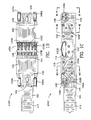
- Fig. 1 is a perspective view 100 of the conduit sensor device including a magnetic shunt illustrating the aft pole 101, the forward pole 102, and sensors 103, 103A, 103B, 103C, 103D, 103E for detecting anomalies or variations in a conduit/pipeline.
- the conduit sensor which includes the magnetic shunt device shown and described herein is one of a plurality of such devices located about the inner periphery of the pipeline/conduit.
- Poles 101, 102 are manufactured from 1018 steel.
- a magnetic field is created by sets of magnets beneath poles 101, 102.
- a first set (aft set) of magnets comprises rare earth permanent magnets 230, 232 and rare earth rotatable magnets 231, 271.
- a second set of magnets comprises rare earth magnets 240, 242 and rare earth rotatable magnets 241, 281.
- the rare earth magnets are NdFeB magnets. Other rare earth magnets may be used. Magnets other than rare earth magnets may be used.
- the device 100 is capable of modifying and/or substantially cancelling the magnetic field between the poles so as to facilitate propulsion of the device and the propelling mechanism (not shown) through the pipeline/conduit. When the poles are active and a magnetic field exists therebetween, the field interacts with a ferromagnetic pipeline and is attracted to said ferromagnetic pipeline.
- the poles 101, 102 and backing bar 225 are the only components that should be made of ferrous materials. All other components such as side plates, end blocks, shunt shaft 301, shunt rotors, etc. are preferably made of non-ferrous material such as aluminum or brass or similar material. This is to maximize the amount of magnetic energy going into the pipeline/conduit wall 252, poles 101, 102, and backing bar 225 instead of going into the side plates 110, 113, end blocks 104, 105, shunt shaft 301, rotor gears 302G, 303G and other components.
- Forward end block 104 and aft (rear) end block 105 are illustrated in the perspective view of Fig. 1 as is the wire groove 105A in the aft end block 105.
- Forward end block 104 and aft end block 105 are secured to backing bar 225 illustrated in Fig. 2 by threaded studs (not shown).
- Wheels 106, 107, 108, 109 and corresponding rubber grips or tires 106A, 107A, 108A, 109A therefor are illustrated in Fig. 1A .
- the rubber grips engage the inner wall of a pipeline/conduit when the device performs an inspection. See Fig. 2C which illustrates pipeline/conduit 252.
- Side plate 110 and wire groove 110A in the side plate 110 are illustrated in the rearward (aft) portion of side plate 110. Further, the forward portion 110F of the side plate is illustrated in Fig. 1A .
- aft and forward are used for points of reference herein. Aft is used to indicate the backward portion nearer stepper motor 111 and the controls/communication interface 112 for stepper motor 111. Forward is used to indicate the front portion opposite the stepper motor 111 and the control interface 112.
- Support arms 177, 177A, 178, 178A support the conduit sensor device and extend and attach to the central propelling mechanism (not shown) of the inspection pig (device).
- the inspection pig (device) drives the plurality of conduit sensors through the pipeline/conduit using a drive means (not shown).
- Saddle 114 supports the sensors 103A-E.
- Bolt holes 120, 121 enable poles 101, 102 to secure be secured to the backing bar 225 as illustrated in Fig. 2 .
- Fig. 1A is another perspective view 100A of the conduit sensor device which includes the magnetic shunt device illustrating the side keeper plate 113 and the wire groove 113A therein.
- Reference numeral 113R denotes the rearward portion of the device in Fig. 1A and reference numeral 11F denotes the forward portion of the device in Fig. 1A .
- Wire grooves 110A, 113A enable routing of wires to the sensors 103A-E.
- Sensors 103A-E may be any type of electronic sensors including, for example, Hall effect sensors which detect anomalies/faults in the wall of the pipeline/conduit.
- Fig. 1B is a top view 100B of the conduit sensor device which includes the magnetic shunt device and Fig. 1C is a side view 100C of the conduit sensor device which includes the magnetic shunt device.
- Fig. 1D is a perspective view 100D of the conduit sensor device which includes the magnetic shunt device without the drive motor attached thereto.
- Rear end block 105 is illustrated in Fig. 1D along with bolt holes 105B for attachment to stepper motor 111. Also shown is flat face 105F which abuts stepper motor 111 when it is attached.
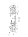
- Fig. 2 is a cross-sectional view 200 of the conduit sensor device including the magnetic shunt device taken along the lines 2-2 of Fig. 1B illustrating input shaft 211S driving input gear 211G.
- Input shaft 211 S is driven by stepper motor 111 not shown in Fig. 2 .
- Screw 220S interengages bolt hole 120 and is threadedly connected to pole 101 which secures first aft permanent magnet 230 and second aft permanent magnet 232 of the aft magnet set to the backing bar 225.
- End blocks 104, 105 are secured to backing bar 225 through threaded connections which are not shown.
- End blocks 104, 105 are affixed to the backing bar 225 and screws 220S, 221S affix poles 101, 102 to the end blocks.
- Permanent magnets 230, 232, 240 and 242 are mechanically clamped into engagement with the poles 101, 102 and the backing bar 225.
- Reference numerals 220T, 221T represent the threaded interengagement of the screws 220S, 221S and the backing bar 225.
- Backing bar 225 includes a shunt shaft channel 520C best viewed in Fig. 5C.
- Fig. 5C is a cross-section view 500C of the backing bar 225 and fixed permanent magnets 230, 232, 240, 242 taken along the lines 5C-5C of the Fig. 5 .
- Gear 318 is affixed to shunt shaft 301 with a set screw 317.
- Gear 316 include gear teeth 318 which drive shunt shaft 301 as illustrated in Fig. 2 and 3 .
- Shunt shaft 301 is supported by: bearings 319B mounted in the aft housing 105, bearings 314B mounted in the backing bar 225/shaft support plate 225P, bearings 310B mounted in the backing bar 225/shaft support plate 225P, bearings 305B mounted in the backing bar 225/shaft support plate and bearings 306B in the backing bar 225/shaft support plate 225P.
- Aft helical worm gear 303W and forward helical worm gear 302W are mounted to shaft 301 and drive rotor gears 303G and 302G, respectively.
- Helical gear 302W is pinned 313 to shaft 301.
- Spacer 311 separates helical gear 303W from bearing 310B.
- Helical gear 303W resides between bearings 314B and 310B. Snap ring 315 secure bearings 314B from leftward lateral movement as illustrated in Fig. 2 . Similarly, forward helical gear 302W is secured to shunt shaft 301 by pin 307. Spacer 305S separates bearing 305B from the helical gear 303W. Bearing 306B abuts forward helical gear 302W and is secured against rightward lateral movement when viewing Fig. 2 by collar 303 which is press-fit on shaft 301.
- permanent magnet 230 includes north 230N and south 230S poles and permanent magnet 232 includes north 232N and south 232S poles.
- Rotatable magnet 231 is shown as being solid in Fig. 2 as the section line 2-2 is taken along the lines 2-2 of Fig. 1D . Section lines 2-2 are coincident with the end surface of rotatable magnet 231.
- Rotatable magnet 231 includes north 231 N and south 231S poles.
- the aft rotatable magnet 231 is actually one-half of the aft rotatable magnet and reference is made to Fig. 4A for an illustration of the aft rotatable magnet halves 231, 271.
- the aft rotatable magnet is described herein as including a first half 231 and a second half 271.
- Rotor gear 303G in combination with the male magnet backers 401 M, 402M, female magnet backers 401 F, 402F, end trunions 460, 471 and screws 473, 474, 463, 464 as illustrated in Fig. 4A secure the first half 231 and second half 271 of the rotatable magnet together to form essentially one rotatable magnets.
- permanent magnet 240 includes north 240N and south 240S poles and permanent magnet 242 includes north 242N and south 240S poles.
- Forward rotatable magnet 241 is shown solid in Fig. 2 as the section line 2-2 is taken along the lines 2-2 of Fig. 1D .
- the forward rotatable magnet is one half of the forward rotatable magnet set 241, 281.
- Rotatable magnet half 241 includes a north pole 241N and a south pole 241S.
- magnet backer extensions 402E and 401 E interfit the interior of the rotor gear 303G and secure magnets 231, 271 in place.
- Rotatable magnets halves 231, 271 also interfit the interior of rotor gear 303G as viewed in Figs. 2 , 4A , and 4D .
- the forward rotor shunt and Figs. 2 , 4F , and 4G magnet backer extensions 432E, 431 E secure forward magnet halves 241, 281 in place.
- Rotatable magnet halves 241, 281 also interfit the interior of rotor gear 302G as viewed in Figs. 2 , 4F , and 4G .
- Wheel shafts 250, 250A for wheels 106, 107, 108 and 109 are illustrated in Fig. 2 in cross-section.
- an unnumbered air gap exists between the aft shunt rotor/ rotatable magnets 231, 271 and backing bar 225, permanent magnets 230, 232, and pole 101.
- an unnumbered air gap exists between the forward shunt rotor/rotatable magnets 241, 281 and backing bar 225, permanent magnets 240, 242 and pole 102.
- the air gaps are between 0.015 to 0.20 inches. It is highly desirable to minimize the air gaps to enhance the magnetic circuit when desired as set forth in the drawings.
- Fig. 4 is a perspective view 400 of the aft rotor shunt illustrating the aft rotatable magnet halves 231, 271, aft rotor gear 303G, male magnet backers 401 M, 402M, female magnet backers 401 F, 402F, and trunions 460, 471.
- Guiding protrusion 461 extends from trunion 460 and functions as a guide within slots formed in side wall 110 as described in detail hereinafter in connection with Fig. 6A .
- Fig. 4J illustrates trunion 471, shaft 4620, and protrusion 461A. Protrusion 461A interengages a slot in side wall 113 which is described in more detail hereinafter.
- Shaft 462S extends from trunion 460.
- Screw 464 is threaded into receptacle 464R of male magnet backer 401 M and through female magnet backer 402F.
- Screw 474 is threaded into a corresponding receptacle 402M.and through female magnet backer 401 F.
- Male extensions 401 E, 402E extend over and below aft rotatable magnets 231, 271 when the aft rotor shunt is assembled as illustrated in Figs. 4 and 4D .
- Male extensions 401 E, 402E include arc-shaped surfaces which interfit interior arc-shaped surfaces 415, 416 of rotor gear 303G and arc shaped cavities 410, 411 in female magnet backers 401 F, 402F as illustrated in Figs. 4A and 4C .
- FIG. 4A is an exploded perspective view 400A of the aft rotor shunt illustrating the aft rotatable magnet halves 231, 271.
- Aft rotatable magnet half 231 includes a north pole 231 N and a south pole 231 S.
- Aft rotatable magnet half 271 includes a north pole 271 N and a south pole 271S.
- Fig. 4B is a front view 400B of the aft rotor gear 303G illustrating worm gear teeth (unnumbered) along with inner flat surfaces 413, 414, and arc-shaped surfaces 415, 416.
- Fig. 4C is a perspective view 400C of one set of male 401 M and female 402F magnet backers of the aft rotor shunt.
- Fig. 4D is a cross-sectional view 400D taken along the lines 4B-4B of Fig. 1C and illustrates the aft rotatable rotor shunt and the aft rotatable magnet halves 231, 271.
- Shafts 462S, 4620 are illustrated residing within bearings 491, 492, respectively.
- Side keeper plate 110 includes a recess 460R housing bearing 491 and side keeper plate 113 includes a recess housing bearing 492.
- Trunion 460 interengages male magnet backer 402M and female magnet backer 402F.
- Screws 464, 474 viewed in Fig. 4A are not illustrated in the cross-sectional view of Fig. 4D .
- Screws 464, 474 are used to fasten male halves 401 M, 402M to the opposite trunion. Additionally, adhesive 495, 495A, 495B, 495C, 495D is used to secure the magnet backers and rotatable magnets together.
- male extension 402E of male magnet backer 402M along with female magnet backer 401 F secures rotatable magnet half 231 from above while male magnet backer 401 M secures rotatable magnet half 231 from below.
- male magnet backer 402M secures rotatable magnet half 271 from above.
- Male extension 401E of male magnet backer 401 M along with female magnet backer 402F secures rotatable magnet half 271 from below.
- helical gear 303W is depicted diagrammatically as meshing with rotor gear 303G. These gear sets are sometimes referred to as worm-worm gear.
- Rotor gear 303G is driven by helical gear 303W.
- Rotatable magnet halves 231, 271 function as a single magnet and are rotated with rotor gear 303G.
- the entire rotor shunt rotates in unison with rotor gear 303G.
- Fig. 4E is a perspective view 400E of the forward rotor shunt.
- Fig. 4F is an exploded perspective view 400F of the forward rotor shunt.
- Fig. 4G is a front view 400G of the forward rotor 302G.
- Fig. 4H is a perspective view 400H of the male 431 M and female 432F magnet backers of the forward rotor shunt.
- Fig. 4I is a cross-sectional view 400I taken along the lines 4I-4I of Fig. 1C .
- the structure of the forward rotor shunt is the same as the aft rotor shunt.
- Fig. 4E is a perspective view 400E of the forward rotor shunt illustrating the forward rotatable magnet halves 241, 281, forward rotor gear 302G, male magnet backers 431 M, 432M, female magnet backers 431 F, 432F and trunions 440, 481.
- Guiding protrusion 441 extends from trunion 440 and functions as a guide within a slot formed in side wall 110 as described in detail hereinafter.
- Fig. 4K illustrates trunion 481, shaft 4420, and protrusion 441A. Protrusion 441A interengages a slot in side wall 113.
- Shaft 462S extends from trunion 440.
- Screw 444 is threaded into receptacle 444R of male magnet backer 431 M and through female magnet backer 432F.
- Screw 484 is threaded into a corresponding receptacle male magnet backer 432M and through male magnet backer 432M and through female magnet backer 431 F.
- Male extensions 432E, 431 E extend over and below forward rotatable magnets 241, 281 when the forward rotor shunt is assembled as illustrated in Figs. 4E and 4I .
- Male extensions 431 E, 432E include arc-shaped surfaces which interfit interior arc-shaped surfaces 415A, 416A of rotor gear 302G and arc shaped cavities 430, 431 as illustrated in Figs. 4F and 4H .
- Fig. 4F is an exploded perspective view 400F of the forward rotor shunt illustrating the forward rotatable magnet halves 241, 281.
- Forward rotatable magnet half 241 includes a north pole 241 N and a south pole 241S.
- Forward rotatable magnet half 281 includes a north pole 281 N and a south pole 281S.
- Fig. 4G is a front view 400G of the forward rotor gear 302G illustrating worm gear teeth (unnumbered) along with inner flat surfaces 413F, 414F, and arc-shaped surfaces 415A, 416A.
- Fig. 4H is a perspective view 400H of one set of male 431 M and female 432F magnet backers of the forward rotor shunt. Male extension 431 E of male magnet backer 431 M interfits cavity 431 of female magnet backer 432F.
- Fig. 4I is a cross-sectional view 400I taken along the lines 4I-4I of Fig. 1C and illustrates the forward rotatable rotor shunt and the forward rotatable magnets 241, 281.
- Shafts 442S, 4420 are illustrated residing within bearings 492A, 491A, respectively.
- Side keeper plate 110 includes a recess 491R housing bearing 492A and side keeper plate 113 includes a recess 490R housing bearing 491A.
- Trunion 481 interengages male magnet backer 431 M and female magnet backer 431 F. Screws 444, 484 viewed in Fig. 4F are not illustrated in the cross-sectional view of Fig. 4I .
- adhesive 496, 496A, 496B, 496C, 496D is used to secure the magnet backers and rotatable magnets together to form the forward rotor shunt.
- male extension 432E of male magnet backer 432M along with female magnet backer 431 F secures rotatable magnet half 241 from above while male magnet backer 431 M secures rotatable magnet half 241 from below.
- male magnet backer 432M secures rotatable magnet half 281 from above.
- Male extension 431 E of male magnet backer 401 M along with female magnet backer 432F illustrates secures rotatable magnet half 281.
- helical gear 302W is depicted diagrammatically as meshing with rotor gear 302G. As stated above, these gear sets are sometimes referred to as worm-worm gear.
- shaft support plate 225P supports shunt shaft bearings as indicated previously and also keeps dirt and debris out of the meshing gears, 303W, 303G and 302W, 302G.
- pole 101 as illustrated is the north pole of the magnetic shunt sensor device.
- Pole 102 as illustrated in Fig. 2 is the south pole of the magnetic shunt sensor device.
- a plurality of magnet shunt sensor devices comprise a pipeline inspection device.
- the aft permanent magnets 230, 232 are positioned with their north poles above their south poles.
- the rotatable magnets 231, 271 are positioned with their respective north poles above the south poles.
- the aft magnet set, 230, 232, 231, 271 as shown creates, in sum, a magnetic north pole on the upper incline of the magnet set and a magnetic south pole on the lower inclined of the magnet set. The inclination of the magnet set does not affect the magnet field created by the magnet set.
- pole 102 as illustrated is the south pole created by the forward magnet set.
- the forward magnets 241, 281 are positioned with their south poles above their north poles.
- the forward permanent magnets 240, 241 are positioned with their south poles above their north poles.
- the forward magnet set, 240, 242, 241, 281 as shown creates, in sum, a magnetic south pole on the upper incline of the magnet set and a magnetic north pole on the lower incline of the magnet set.
- the aft rotor shunt and aft rotatable magnets 231, 271 and the forward rotor shunt and forward rotatable magnets are in home position.
- protrusion 461 is shown in home position as indicated by reference numeral 660H.
- Home position is defined as the position of the rotor shunt and the aft rotatable magnets as illustrated in Fig. 2 .
- the protrusion 461 is aligned with the rotatable magnets.
- protrusion 441 is illustrated in home position in Fig. 6C .
- Arrows 669F, 669A indicate the direction of rotation of the rotor shunt beginning at the home position as indicated by the position of the protrusion 461 in arcuate slot 660C and the position of the protrusion 441 in arcuate slot 680C.
- Fig. 6 illustrates 600 the outside of the side keeper plate (side plate) 110 of the magnetic sensor shunt device.
- the side plate is affixed to the backing bar with unnumbered threaded connections such as those illustrated in Fig. 1 .
- Reference numeral 603 indicates an opening for the saddle 114.
- Reference numeral 110F signifies the forward portion of the device and reference numeral 110R signifies the aft or rear portion of the device.
- Fig. 6A illustrates 600A the inside of the side keeper 110 of Fig. 6 .
- a first arcuate slot 660C is illustrated generally in the aft or rear portion 110R of the side keeper (side plate) 110.
- Receptacle 460R houses bearing 491which supports the shaft of the aft rotor shunt.
- Receptacle 460R is centrally located with respect to arcuate slot 660C.
- protrusion 461 resides in slot 660C and is guided therein.
- Slot 660C serves to limit the travel of the protrusion and, hence, the aft rotor shunt.
- Slot 660C also orients protrusion 461 and aft rotatable magnet halves 231, 271 in their home position during assembly.
- FIG. 6A and 6C home positions 660H, 680H of protrusions 461, 441 are shown, respectively.
- Arrows 669F, 669A indicates the direction of rotation of the aft rotor shunt and forward rotor shunt, respectively.
- Home positions 660H, 680H are referred to herein as being at 0° in an arc which ranges from 0° to 180°.
- Reference numerals 660F, 680F indicate the final position, 180°, from the initial, home position. "Final" as used herein is just a reference position and it does not mean a permanent position as the protrusions may be driven to any one of the positions available between 0° and 180°.
- Protrusions 461, 442 may move through an angle of 180° between home position 660H and final position 660F.
- a second arcuate slot 680C is illustrated generally in the forward portion 110F of the side keeper 110.
- Receptacle 491 R houses bearing 492A which supports the shaft of the forward rotor shunt.
- Receptacle 491 R is centrally with respect to slot 680C.
- protrusion 441 resides in slot 680C and is guided therein.
- Slot 680C also orients protrusion 441 and the forward rotatable magnet halves 241, 281 in their home position during assembly.
- Aft arcuate slot 660C allows protrusion 461 to make a 180° arc.
- Home position 660H and final position 660F function as stops or limits.
- forward arcuate slot 680C allows protrusion 441 to make a 180° arc.
- Home position 680H and final position 680F function as stops or limits.
- the protrusions 461, 444, and hence the rotor shunts and rotatable magnets may be driven bidirectionally by shunt shaft 301, helical gears 302W, 303W and rotor gears (worm gears) 302G, 303G to any desired position between 0° (home position) to 180° (final position).
- the forward and aft helical gears 302W, 303W are driven in the same direction and rotor gears 302G, 303G follow in the same rotational direction.
- shunt shaft 301 is rotated in the clockwise direction (as viewed from the end of shaft 301 supported by bearing 319B)
- worm gears 302G, 303G are rotated in the same clockwise direction.
- worm gears 302G, 303G will be rotated in the counterclockwise direction.
- aft and forward rotor shunts and rotatable magnets can only be rotated in the clockwise direction as the protrusions are in their home positions.
- the rotatable magnets are in the positions illustrated in Figs. 2A , 2D and the 461, 441 engage stop 660F, 680F as illustrated in Fig. 6C .
- Fig. 6B is a cross-sectional view 600B taken along the lines 6B-6B of Fig. 6A illustrating the bearing receptacle 460R and the first arcuate slot (aft slot) in the side plate 110.
- Poles 101, 102 and backing bar 225 are ferromagnetic.
- Backing bar 225 is made of 1008 steel capable of carrying a higher magnetic field than typical 1018 steel.
- Poles 101, 102 are made of 1018 steel.
- Fig. 2C is a schematic cross-sectional view 200C of the conduit sensor device which includes the magnetic shunt device similar to Fig. 2 with magnetic field lines 251 illustrated.
- Each of the permanent and rotatable magnets has a BH product of 45MGOe which equates to 358.1 kJ/m .
- the combined surface area of permanent magnets 230 and 232 in the aftrotor shunt is equal to the combined surface area of the aft rotatable magnets 231, 271.
- the combined (total) surface area of permanent magnets 240, 242 of the forward rotor shunt is equal to the combined (total) surface area of the forward rotatable magnets 241, 281.
- Fig. 5D a diagrammatic view of the aft magnets including the rotatable magnet which illustrates the approximate relative size of the permanent magnets and the rotatable magnets for both the aft and the forward poles.
- FIG. 2C the home position of the rotatable magnets is illustrated.
- the home position of the rotatable magnets is also shown in Fig. 2 .
- the pipe wall 252 is illustrated with a thickness and the magnetic field 251 is illustrated passing entirely through the wall of the pipe 252.
- the rotatable magnets are illustrated and reference numerals 231, 271 indicate the rotatable magnet halves.
- the thickness of the permanent magnets 230, 232 and the rotatable magnets 231, 271 are equal and the obverse sides of the magnets are equal in area to the viewable sides.
- the surface area of permanent magnets 230, 232 equal the surface area of the rotatable magnets 231, 271.
- the invention is not limited to any particular size permanent or rotatable magnets size.
- Fig. 2A is a cross-sectional view of the conduit sensor device which includes the magnetic shunt device taken along the lines 2-2 of Fig. 1B with the rotatable shunting magnets rotated 180° from their initial positions to their final positions. Home positions of the rotatable magnets are the same as the home position of the protrusions associated with rotatable magnets.
- the rotor shunts and the rotatable magnets carried therewith are synchronously driven by the shunt shaft 301 as dictated by the stepper motor.
- Fig. 2D is a schematic cross-sectional view 200D of the conduit sensor device which includes a magnetic sensor shunt device similar to Fig.
- Fig. 2B is a cross-sectional view 200B of the conduit sensor device which includes the magnetic shunt device taken along the lines 2-2 of Fig. 1B with the rotatable shunting magnets rotated (231, 271 and 241, 281) 90° from their initial positions.
- Fig. 2E is a schematic cross-sectional view 200E of the conduit sensor device which includes the magnetic shunt device similar to Fig. 2B with the rotatable shunting magnets 231, 271 and 241, 281 rotated 90° from their initial, home, positions with magnetic field lines illustrated by reference numeral 261. As illustrated in Fig. 2E , the magnetic field lines 261 extend only partially into the conduit/pipeline wall 252.
- Fig. 2F is a cross-sectional view 200F of another example of the invention wherein one permanent magnet 230 is in proximity with rotatable magnets 231, 271 and wherein one permanent magnet 242 is in proximity with rotatable magnets 241, 281.
- the rotor shunts/rotatable magnets used in the example of Fig. 2F are driven as previously described herein and have the same structure as previously described herein.
- the drive structure, namely, the shunt shaft and gears, used in the example of Fig. 2F is as previously described herein in connection with the example of Figs. 2-2E and, as such, is not repeated herein.
- Fig. 3 is a top view 300 of the shunt shaft illustrating the aft 303W and forward 302W worms (helical gears) mounted on shunt shaft 301. Both worm gears rotate in the same direction and are of the same orientation.
- Figs. 3 and 3A provide larger and better views of the shunt shaft described above in connection with Fig. 2 .
- Fig. 3A is a cross-sectional view 300A taken along the lines 3A-3A of Fig. 3 and provides a larger and better view of the shunt shaft as described above in connection with Fig. 2 .
- Fig. 5 is a top view 500 of the backing bar 225 and fixed permanent magnets 230, 232, 240, and 242.
- Fig. 5A is a side view 500A of the backing bar and fixed permanent magnets.
- Seat 503 for saddle 114 is illustrated.
- Aft semi-cylindrically shaped opening 501 and forward semi-cylindrically shaped opening 502 in backing bar 225 are illustrated in Fig. 5A .
- the aft and forward rotor shunts illustrated in Figs. 4 and 4E are generally cylindrical in nature.
- Side keeper plates 110 and 113 as illustrated in Figs.
- 6, 6A, 6B and 6C support the rotor shunts and position them within the semi-cylindrical openings 501, 502, respectively.
- the aft and forward rotor shuns are supported in the bearings and are spaced apart from the semi-cylindrically shaped openings 501, 502.
- the aft and forward rotatable shunts do not engage the backing bar 225 or poles 101, 102.
- openings 504, 505 in the backing bar accommodate the placement of rotor gears 303G, 302G partially therein, respectively, for meshing engagement with helical gears 303W, 303G mounted on shunt shaft 301.
- Fig. 5B is a bottom view 500B of the backing bar illustrating cavities 510, 510A which allow needed space for the helical gears 303W, 303G and effectively keep the size of the device to a minimum.
- Shunt shaft 301 resides in channel 520C. See Fig. 5C , a cross-sectional view taken along the lines 5C-5C of Fig. 5 .
- Channel 520C in the backing bar 225 allows room for shunt shaft 301 to reside therein.
- Fig. 7 is a side view 700 of the aft pole 101.
- Aft pole 101 has the same structure as forward pole 102.
- Fig. 7A is an end view 700A of the aft pole.
- Fig. 7B is a rear view 700B of the aft pole 101.
- Fig. 7C is a bottom view 700C of the aft pole.
- Reference numeral 701 indicates a semi-circular opening in aft pole 101 which accommodates the curvature of the aft rotor shunt which is generally cylindrically shaped.
- Surface 702 of pole 101 interengages first aft permanent magnet 230 of aft magnet set and surface 703 interengages second aft permanent magnet 232 of aft magnet set.
- Rear surface of aft pole 101 includes screw hole 706. Screw 220S viewed in Fig. 2 threadedly 220T interconnects with screw hole 706.
- Fig. 8 is an end view 800 of the forward end block.
- Fig. 8A is perspective view 800A of the forward end block 104.
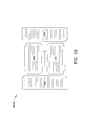
- Fig. 9 is an end view 900 of the aft end block 105 taken along the lines 9-9 of Fig. 1D .
- Fig. 9A is a perspective end view 900A of the forward end block 105 illustrating bolt holes 105 for interconnection to stepper motor 11.
- Reference numeral 105F indicates the flat mating surface of the end block 105.
- a process for modifying a magnetic field generated between magnetic poles with the magnetic field 251, 251 in proximity to a ferromagnetic conduit 252 includes the steps of: driving, bidirectionally, a shunt shaft 301 having first 303W and second 302W helical gears; rotating, using the first helical gear and a first rotor gear 303G, a first rotor shunt residing intermediate a first set of permanent magnets 230, 232 forming a first magnetic pole 101, the first rotor shunt includes a first rotatable magnet 231, 271 rotating therewith; synchronously rotating, using the second helical gear 302W and a second rotor gear 302G, a second rotor shunt residing intermediate a second set of permanent magnets 240, 242 forming a second magnetic pole 102, the second rotor shunt includes a second rotatable magnet 241, 281 rotating therewith; discontinuing the rotation of the first rotor
- the process may be performed with a first rotor shunt which includes a protrusion 461 extending therefrom and second rotor shunt which includes a protrusion 441 extending therefrom.
- the process includes the further step of: guiding and interengaging the protrusion 461 of the first rotor shunt in a first arcuate slot 660C in a side wall 110.
- the first arcuate slot 660C extending between 0°, home position, and 180°, final position.
- the process further includes the step of guiding and interengaging the protrusion 441 of the second rotor shunt in a second slot 680C in side wall 110.
- the second arcuate slot 680C extending between 0°, home position, and 180°, final position.
- One of the features of the process for modifying a magnetic field generated between magnetic poles, 101, 102 includes cancelling the magnetic field when the rotation of the protrusions of the first and second rotor shunts are positioned in the first and second slots at 180°. See Fig. 2A and 2C .
- the conduit sensor device comprises first and second pairs of permanent magnets.
- the first pair of permanent magnets includes a first magnet and a second magnet.
- the first and second magnets include outer surfaces, the outer surfaces of the first magnet have a first area and the outer surfaces of the second magnet have a second area.
- the second pair of permanent magnets includes a fifth magnet and a sixth magnet and the fifth and the sixth magnets include outer surfaces.
- the outer surfaces of the fifth magnet have a fifth area and the outer surfaces of the sixth magnet have a sixth area.
- a first rotor shunt is interposed between the first pair of permanent magnets and a second rotor shunt is interposed between the second pair of permanent magnets.
- a shunt shaft runs the length of the device and includes a first helical worm gear and a second helical worm gear mounted thereon.
- the first rotor shunt includes a first rotatable magnet and a first rotor gear and the first rotatable magnet and the first rotor gear are locked together such that the first rotatable magnet rotates with the first rotor gear.
- the first helical worm gear meshes with the first rotor gear and drives the first rotor gear and the first rotatable magnet.
- the second rotor shunt includes a second rotatable magnet and a second rotor gear.
- the second rotatable magnet and the second rotor gear are locked together such that the second rotatable magnet rotates with the second rotor gear.
- the second helical worm gear meshes with the second rotor gear and drives the second rotor gear and the second rotatable magnet.
- the first rotatable magnet is comprised of a third and fourth magnet.
- the third and fourth rotatable magnets include outer surfaces, the outer surface of the third magnet has a third area and the outer surface of the fourth magnet includes a fourth area.
- the second rotatable magnet is comprised of a seventh and eighth magnet.
- the seventh and eighth magnets include outer surfaces.
- the outer surface of the seventh magnet has a seventh area and the outer surface of the eight magnet includes an eighth area.
- the area of the first magnet and the area of the second magnet when combined, equal the combined area of the third and fourth magnets.
- the area of the fifth magnet and the area of the sixth magnet when combined, equal the combined area of the fifth and sixth magnets.
- the first rotatable magnet and the second rotatable magnet are synchronously rotated and positioned.
Abstract
Description
- The invention is in the field of pipeline inspection devices/sensors.
- United States Patent No.
6,762,602 to Laursen et al. proposed a "device, e.g. an inspection pig, for inspecting conduits made from ferromagnetic materials, such as pipelines, for faults, cracks, corrosion or the like, comprising at least one pulling element, a supporting structure of variable circumference, disposed on the pulling element and comprising substantially radially disposed supporting arms each of which is pivotable about axes disposed perpendicular to the longitudinal central axis of the pulling element, and several permanent magnets disposed at the circumference of the supporting structure for generating a magnetic filed, and with sensors." Further, Laursen, states: "for strengthening or weakening the magnetic field generated by the permanent magnet in dependence on the circumference of the supporting structure or in dependence on the lateral separation between the permanent magnets. The permanent magnets are associated with further magnets having a magnetic field which can be varied in direction or strength. In an embodiment, the further magnets associated with the permanent magnets are permanent magnets, wherein the direction of their magnetic field can be changed by turning using an electric or mechanical actuator. In another embodiment coils are used as magnets, which can be supplied with a variable current." See, the Abstract of United States Patent No.6,762,602 to Laursen et al. - The diametrical size of the conduit, the thickness of the conduit, and the lateral separation of the poles of the magnet are factors in the performance of the sensor. Sensors such as piezo-electric, electro-acoustic, and electromagnetic sensors such as Hall, stray flux and eddy current sensors may be used.
- United States Patent No.
6,762,602 to Laursen et al. does not effectively shunt the magnetic field produced by the poles through use of respective rotatable magnets. Additionally, the drive system of the rotatable magnets disclosed in United States Patent No.6,762,602 to Laursen et al. involves a mechanical system using springs and a toothed wheel with a selected diameter and selected number of teeth. The diameter and the number of teeth may be changed to control the rotatable magnet. Further, a spring is necessary for each of the rotatable magnets and adjustment of those magnets in a coordinated manner is difficult, and, therefore, control of the magnetic field is difficult. One of the poles in the Laursen '602 patent may be adjusted differently than the other pole because the springs and toothed gears cannot be matched or properly controlled. Spring constants and biasing of the rotatable magnets in Laursen et al. may not be equal and, hence, contribution of each of the poles to the magnetic field may be different. - Alternatively, United States Patent No.
6,762,602 to Laursen et al. , further discloses an electrically driven toothed wheel which is controlled by appropriate electric, electronic or mechanical sensor element for determining the lateral separation between the parallelogram supports. However, there is no disclosure in Laursen as to the coordinated operation and control of the rotatable magnets. - A more effective magnetic shunt which substantially completely reduces the magnetic field associated with a plurality of inner peripheral sensors is needed for unpiggable pipe lines. So-called unpiggable pipe lines require substantial cancellation of the magnetic field caused by permanent magnets used in conduit sensors placed in proximity to the conduit/pipe line. When the field created by the permanent magnets is substantially cancelled, the sensor may be drawn more easily through the pipeline as the sensor and its supporting structure are no longer magnetically attracted to the walls of the conduit/pipeline.
- Use of a conduit sensor device requires application of north and south poles in proximity to the conduit/pipe line wall which creates a magnetic field extending into the wall of the conduit/pipe line. Control of the magnetic field which enters the conduit/pipe line is necessary for the correct interpretation of data obtained from the sensors. Sensors, such as Hall Effect sensors, measure anomalies such as cracks and deterioration of the structure of the conduit/pipeline when a magnetic field is imparted in the conduit/pipeline. Control of the magnetic field imparted in the conduit/pipeline is important as it allows correct interpretation of the data generated from the sensors. As such, a conduit sensor device which accurately controls the magnetic field in the conduit/pipeline wall is needed.
- There are a plurality of conduit sensor devices arranged on the inner periphery of the pipeline/conduit which form an inspection pig. Each conduit sensor device includes several sensors associated therewith and each device covers a sector of the pipeline/conduit. Sixteen (more or less) conduit sensor devices may be used to cover the full inner surface of a cylindrically shaped pipeline/conduit. Any number of conduit sensors may be used to form an inspection pig.
- Each conduit sensor device includes a magnetic shunt device. The magnetic shunt device is used effectively turns off the magnetic field. The inspection pig is propelled through the pipeline/conduit by drive means which are not shown. Each of the conduit sensor devices are connected to the drive means. Further, and importantly, the magnetic shunt device enables the curtailment of the magnetic field in the pipeline/conduit making movement of the inspection pig within the interior of the pipeline/conduit and through valves and other obstructions inside the pipeline easier. As stated above the inspection pig is driven by drive means not shown.
- Further, the magnetic shunt device imparts an appropriately adjustable magnetic field into the pipeline/conduit as dictated by the operation of the inspection pig and/or as required for other reasons such as comparison of the data presently being taken against previously taken data for a given conduit/pipeline.
- The conduit sensor device includes first and second pairs of permanent magnets. First and second rotor shunts include first and second rotatable magnets interposed between the first and second pairs of permanent magnets, respectively. A shunt shaft includes a first helical worm gear and a second helical worm gear mounted thereon. Both helical gears are right handed. The first rotor shunt includes a first rotatable magnet and a first rotor gear locked together. The first helical worm gear meshes with the first rotor gear driving the first rotor gear and the first rotatable magnet. The second rotor shunt includes a second rotatable magnet and a second rotor gear locked together. The second helical worm gear meshes with the second rotor gear driving the second rotor gear and the second rotatable magnet. The surface areas of the first pair of permanent magnets equals the surface area of the first rotatable magnet. Similarly, the surface areas of the second pair of permanent magnets equals the surface area of the second rotatable magnet.
- The conduit sensor device includes an aft pole having includes an aft magnet set comprised of a first aft permanent magnet, a second aft permanent magnet, and a first rotatable magnet interposed between the first aft permanent magnet and the second aft permanent magnet. A forward pole includes a forward magnet set. The forward magnet set includes a first forward permanent magnet, a second permanent magnet, and a second rotatable magnet interposed between the first forward permanent magnet and the second permanent magnet. A sensor is interposed between the aft magnet set and the forward magnet set.
- A backing bar supports the first aft permanent magnet, the second aft permanent magnet, the first forward permanent magnet, and the second forward permanent magnet. The first pole piece secures the first permanent magnet and the second permanent magnet to the backing bar. The second pole piece secures the first forward permanent magnet and the second permanent magnet to the backing bar.
- A shunt shaft runs approximately the length of the device and includes an aft helical worm gear and a forward helical worm gear. Both worm gears are right handed helical gears. A first rotor worm gear meshes in engagement with the shaft driven device aft helical worm gear and a second rotor worm gear meshes in engagement with the shaft driven forward helical worm gear. The first rotatable magnet is in rotating engagement with the first rotor worm gear. The second rotatable magnet is in rotating engagement with the second rotor worm gear.
- The first rotatable magnet includes a first half and a second half. The second rotatable magnet includes a first half and a second half. The first half of the first rotatable magnet and the second half of the first rotatable magnet are affixed to the first rotor worm gear. Similarly, the first half of the second rotatable magnet and the second half of the second rotatable magnet are affixed to the second rotor worm gear.
- A bidirectional motor is coupled to the shunt shaft rotating the aft helical worm gear, the first rotor worm gear and the first rotatable magnet as well as the forward helical worm gear, the second rotor worm gear and the second rotatable magnet.
- The first rotor shunt, the first rotatable magnet halves, the second rotor shunt and the second rotatable magnet halves are synchronously rotated and positioned. The shunt shaft is driven bidirectionally and the first and second rotor gears are driven bidirectionally and synchronously. The rotatable magnets mechanically coupled to the rotor gears rotate bidirectionally, in the same direction, and synchronously.
- The conduit sensor assembly includes a first side keeper plate and a second side keeper plate. The first keeper plate includes a first arcuate slot and a second arcuate slot. The second keeper plate includes a first arcuate slot and a second arcuate slot. The first rotor shunt includes a first end trunion and a second end trunion. The first end trunion of the first rotor shunt includes a first protrusion and the second end trunion of the first rotor shunt includes a second protrusion. The protrusions of the first and second end trunions of the first rotor shunt reside in and are guided in the first arcuate slots, respectively, of the first and second keeper plates. The second rotor shunt includes a first end trunion and a second end trunion. The first end trunion of the second rotor shunt includes a first protrusion. The second end trunion of the second rotor shunt includes a second protrusion. The protrusions of the first and second end trunions of the second rotor shunt reside in and are guided in the second arcuate slots, respectively, of the first and second keeper plates.
- The first arcuate slot of the first keeper plate extends 180° from a home position to a final position and the first arcuate slot of the second keeper plate extends 180° from a home position to a final position. The home positions and the final positions limit the travel of the protrusions/rotor shunts/rotatable magnets. Home and final positions are stops. The protrusion of the first end trunion of the first rotor shunt resides in the first arcuate slot of the first keeper plate and is movable between the home position and the final position of the first arcuate slot of the first keeper plate. The protrusion of the second end trunion of the first rotor shunt resides in the first arcuate slot of the second keeper plate and is movable between the home position and the final position of the first arcuate slot of the second keeper plate. The second arcuate slot of the first keeper plate extends 180° from a home position to a final position and the second arcuate slot of the second keeper plate extends 180° from a home position to a final position. The protrusion of the first end trunion of the second rotor shunt resides in the second arcuate slot of the first keeper plate and is movable between the home position and the final position of the second arcuate slot of the first keeper plate. The protrusion of the second end trunion of the second rotor shunt resides in the second arcuate slot of the second keeper plate and is movable between the home position and the final position of the second arcuate slot of the second keeper plate.
- The first set of magnets form a first magnetic pole and the second set of magnets form a second magnetic pole. The first and second magnetic poles include a magnetic field therebetween which, when in use during an inspection, reside partially in the pipeline/conduit to be inspected. The first rotor gear is capable of rotating the first rotor shunt and the first rotatable magnet 180° from home position to final position. The second rotor gear, rotating synchronously with the first rotor gear, is capable of rotating the second rotor shunt and the second rotatable magnet 180°. The first and second rotatable magnets substantially cancel the magnetic field located between the first and the second magnetic poles when rotated to their final positions.
- The first rotor gear rotates the first rotor shunt and the first rotatable magnet between 0° and 180° synchronously with the second rotor gear rotating the second rotor shunt and the second rotatable magnet between 0° to 180°. Positioning of the first and second rotatable magnets between the respective permanent magnets moderates the magnetic field located between the first and the second magnetic poles.
- A stepper motor bidirectionally drives the shunt shaft, the helical worm gears, the rotor gears, the rotor shunts and the first and second rotatable magnets.
- A process for modifying a magnetic field generated between magnetic poles with the magnetic field in proximity to a ferromagnetic conduit is disclosed and claimed. The process includes the steps of: (1) driving, bidirectionally, a shunt shaft having first and second helical gears; (2) rotating, using the first helical gear and a first rotor gear, a first rotor shunt residing intermediate a first set of permanent magnets forming a first magnetic pole, the first rotor shunt includes a first rotatable magnet rotating therewith; (3) synchronously rotating, using the second helical gear and a second rotor gear, a second rotor shunt residing intermediate a second set of permanent magnets forming a second magnetic pole, the second rotor shunt includes a second rotatable magnet rotating therewith; (4) discontinuing the rotation of the first rotor shunt and the second rotor shunt synchronously positioning the first rotatable magnet intermediate the first set of permanent magnets and the second rotatable magnet intermediate the second set of permanent magnets; and, (5) modifying the magnetic field generated between the magnet poles. The steps of: (1) rotating, using the first helical gear and a first rotor gear, a first rotor shunt residing intermediate a first set of permanent magnets forming a first magnetic pole, the first rotor shunt includes a first rotatable magnet rotating therewith, and, (3) synchronously rotating, using the second helical gear and a second rotor gear, a second rotor shunt residing intermediate a second set of permanent magnets forming a second magnetic pole, the second rotor shunt includes a second rotatable magnet rotating therewith; include rotating the first and second shunt rotors between 0° and 180° , the first and second rotatable magnets rotating therewith, respectively.
- The process may be performed with a first rotor shunt which includes a protrusion extending therefrom and second rotor shunt which includes a protrusion extending therefrom. The process includes the further step of: guiding and interengaging the protrusion of the first rotor shunt in a first arcuate slot in a side wall. The first arcuate slot extending between 0° and 180°. The process further includes the step of guiding and interengaging the protrusion of the second rotor shunt in a second slot in a side wall. The second arcuate slot extending between 0° and 180°.
- One of the features of the process for modifying a magnetic field generated between magnetic poles includes cancelling the magnetic field when the rotation of the protrusions of the first and second rotor shunts are positioned in the first and second slots at 180°.
- Another example of the conduit sensor device comprises first and second pairs of permanent magnets. The first pair of permanent magnets includes a first magnet and a second magnet. The first and second magnets include outer surfaces, the outer surfaces of the first magnet have a first area and the outer surfaces of the second magnet have a second area. The second pair of permanent magnets includes a fifth magnet and a sixth magnet and the fifth and the sixth magnets include outer surfaces.
- The outer surfaces of the fifth magnet have a fifth area and the outer surfaces of the sixth magnet have a sixth area. A first rotor shunt is interposed between the first pair of permanent magnets and a second rotor shunt is interposed between the second pair of permanent magnets. A shunt shaft runs the length of the device and includes a first helical worm gear and a second helical worm gear mounted thereon.
- The first rotor shunt includes a first rotatable magnet and a first rotor gear and the first rotatable magnet and the first rotor gear are locked together such that the first rotatable magnet rotates with the first rotor gear. The first helical worm gear meshes with the first rotor gear and drives the first rotor gear and the first rotatable magnet. The second rotor shunt includes a second rotatable magnet and a second rotor gear. The second rotatable magnet and the second rotor gear are locked together such that the second rotatable magnet rotates with the second rotor gear. The second helical worm gear meshes with the second rotor gear and drives the second rotor gear and the second rotatable magnet. The first rotatable magnet is comprised of a third and fourth magnet. The third and fourth rotatable magnets include outer surfaces, the outer surface of the third magnet has a third area and the outer surface of the fourth magnet includes a fourth area. The second rotatable magnet is comprised of a seventh and eighth magnet. The seventh and eighth magnets include outer surfaces. The outer surface of the seventh magnet has a seventh area and the outer surface of the eighth magnet includes an eighth area. The area of the first magnet and the area of the second magnet, when combined, equal the combined area of the third and fourth magnets. The area of the fifth magnet and the area of the sixth magnet, when combined, equal the combined area of the fifth and sixth magnets. The first rotatable magnet and the second rotatable magnet are synchronously rotated and positioned.
- It is an object of the invention to substantially completely reduce the magnetic field for use in so-called unpiggable pipe lines.
- It is a further object of the invention to substantially cancel the magnetic field between the poles of the device so that the device may be drawn more easily through the pipeline as the sensor and its supporting structure are no longer magnetically attracted to the walls of the conduit/pipeline.
- It is a further object of the invention to control the magnitude of the magnetic field which enters the conduit/pipe line.
- It is a further object of the invention to control the magnetic field imparted in the conduit/pipeline to allow correct interpretation of the data generated from the sensors.
- It is a further object of the invention to control the magnetic field in the conduit/pipeline wall for a wide variety of pipe diameters and for a wide variety of pipe thicknesses.
- It is a further object of the invention to synchronously control the magnetic field created by the aft and forward magnetic poles of the pipeline inspection device.
- It is a further object of the invention to mechanically prevent the over travel of the rotor shunts and the rotatable magnets of the pipeline inspection device.
- It is a further object of the invention to substantially cancel the entire magnetic field of the pipeline inspection device to enable negotiation within the conduit/pipeline.
- It is a further object of the invention to cancel a portion of the magnetic field of the pipeline inspection device to enable use of the pipeline inspection device in different environments.
- It is a further object of the invention to provide rotor shunts having magnets rotating therewith between 0°-180° for modifying and/or cancelling the magnetic field between two magnetic poles.
- It is a further object of the invention to synchronously position the aft and forward rotatable magnets.
- It is a further object of the invention to precisely and simultaneously position the aft and forward rotatable magnets.
- It is a further object of the invention to use rare earth permanent magnets.
- It is a further object of the invention to use rare earth rotatable magnets.
- It is a further object of the invention to use 1008 steel as the material for the backing bar.
- According to one aspect of the invention the objects are solved for a conduit sensor device. This conduit sensor device comprising:
- an aft pole, said aft pole includes an aft magnet set, said aft magnet set includes a first aft permanent magnet, a second aft permanent magnet, and a first rotatable magnet interposed between said first aft permanent magnet and said second aft permanent magnet;
- a forward pole, said forward pole includes a forward magnet set, said forward magnet set includes a first forward permanent magnet, a second permanent magnet, and a second rotatable magnet interposed between said first forward permanent magnet and said second permanent magnet; and,
- a sensor interposed between said aft magnet set and said forward magnet set.
- Especially said conduit sensor device comprising further:
- a backing bar supporting said first aft permanent magnet and said second permanent magnet;
- a backing bar supporting said first forward permanent magnet and said second permanent magnet; means for securing said first permanent magnet and said second permanent magnet to said backing bar; and,
- means for securing said first forward permanent magnet and said second permanent magnet to said backing bar.
- According to a preferred embodiment of said conduit sensor device the following features are provided: a shunt shaft;
said shunt shaft includes an aft helical worm gear and a forward helical worm gear;
a first rotor worm gear in meshing engagement with said aft helical worm gear;
a second rotor worm gear in meshing engagement with said forward helical worm gear;
said first rotatable magnet in rotating engagement with said first rotor worm gear; and,
said second rotatable magnet in rotating engagement with said second rotor worm gear. - Especially, said first rotatable magnet includes a first half and a second half; and, said second rotatable magnet includes a first half and a second half.
- Said first half of said first rotatable magnet and said second half of said first rotatable magnet can be affixed to said first rotor worm gear; and said first half of said second rotatable magnet and said second half of said second rotatable magnet can be affixed to said second rotor worm gear.
- According to a further preferred embodiment of the invention a bidirectional motor is provided, said bidirectional motor coupled to said shunt shaft, said shunt shaft rotating said aft helical worm gear, said first rotor worm gear and said first rotatable magnet; and, said shunt shaft rotating said forward helical worm gear, said second rotor worm gear and said second rotatable magnet.
- According to a further aspect of the invention the objects are solved for a further conduit sensor device. This conduit sensor device comprising:
- a first set of permanent magnets; a first rotor shunt interposed between said first set of permanent magnets;
- a second set of permanent magnets;
- a second rotor shunt interposed between said second set of permanent magnets;
- a shunt shaft, said shunt shaft includes a first helical worm gear and a second helical worm gear mounted thereon;
- said first rotor shunt includes a first rotatable magnet and a first rotor gear, said first rotatable magnet and said first rotor gear being locked together such that said first rotatable magnet rotates with said first rotor gear, said first helical worm gear meshing with said first rotor gear and driving said first rotor gear and said first rotatable magnet;
- said second rotor shunt includes a second rotatable magnet and a second rotor gear, said second rotatable magnet and said second rotor gear being locked together such that said second rotatable magnet rotates with said second rotor gear, said second helical worm gear meshing with said second rotor gear and driving said second rotor gear and said second rotatable magnet;
- a sensor interposed between said first rotor shunt and said second rotor shunt;
- said first rotatable magnet and said second rotatable magnet are synchronously rotated and positioned.
- According to a preferred embodiment of said conduit sensor device said shunt shaft is driven bidirectionally and said first and second rotor gears are driven bidirectionally and synchronously.
- Especially said conduit sensor device comprises:
- a first side keeper plate and a second side keeper plate;
- said first keeper plate includes a first arcuate slot and a second arcuate slot;
- said second keeper plate includes a first arcuate slot and a second arcuate slot;
- said first rotor shunt includes a first end trunion and a second end trunion, said first end trunion of said first rotor shunt includes a protrusion, said second end trunion of said first rotor shunt includes a second protrusion, said protrusions of said first and second end trunions of said first rotor shunt reside in and are guided in said first arcuate slots, respectively, of said first and second keeper plates; and,
- said second rotor shunt includes a first end trunion and a second end trunion, said first end trunion of said second rotor shunt includes a protrusion, said second end trunion of said second rotor shunt includes a second protrusion, said protrusions of said first and second end trunions of said second rotor shunt reside in and are guided in said second arcuate slots, respectively, of said first and second keeper plates.
- According to a further embodiment of said conduit sensor device said first arcuate slot of said first keeper plate extends 180° from a home position to a final position, said first arcuate slot of said second keeper plate extends 180° from a home position to a final position, said protrusion of said first end trunion of said first rotor shunt resides in said first arcuate slot of said first keeper plate and is movable between said home position and said final position of said first arcuate slot of said first keeper plate, said protrusion of said second end trunion of said first rotor shunt resides in said first arcuate slot of said second keeper plate and is movable between said home position and said final position of said first arcuate slot of said second keeper plate;
said second arcuate slot of said first keeper plate extends 180° from a home position to a final position, said second arcuate slot of said second keeper plate extends 180° from a home position to a final position, said protrusion of said first end trunion of said second rotor shunt resides in said second arcuate slot of said first keeper plate and is movable between said home position and said final position of said second arcuate slot of said first keeper plate, and, said protrusion of said second end trunion of said second rotor shunt resides in said second arcuate slot of said second keeper plate and is movable between said home position and said final position of said second arcuate slot of said second keeper plate. - Especially said first set of magnets form a first magnetic pole; said second set of magnets form a second magnetic pole; said first and second magnetic poles include a magnetic field therebetween; said first rotor gear rotating said first rotor shunt and said first rotatable magnet 180° and said second rotor gear rotating said second rotor shunt and said second rotatable magnet 180° substantially cancelling said magnetic field located between said first and said second magnetic poles; and/or said first rotor gear rotating said first rotor shunt and said first rotatable magnet between 0° and 180° synchronously with said second rotor gear rotating said second rotor shunt and said second rotatable magnet between 0° to 180°, said rotation of said first and second rotatable magnets moderating said magnetic field located between said first and said second magnetic poles.
- Furthermore, a stepper motor is provided, said stepper motor drives bidirectionally said shunt shaft.
- According to a further aspect of the invention the objects are solved by a process for modifying a magnetic field generated between magnetic poles, said magnetic field in proximity to a ferromagnetic conduit, comprising the steps of:
- driving, bidirectionally, a shunt shaft having first and second helical gears;
- rotating, using said first helical gear and a first rotor gear, a first rotor shunt residing intermediate a first set of permanent magnets forming a first magnetic pole, said first rotor shunt includes a first rotatable magnet rotating therewith;
- synchronously rotating, using said second helical gear and a second rotor gear, a second rotor shunt residing intermediate a second set of permanent magnets forming a second magnetic pole, said second rotor shunt includes a second rotatable magnet rotating therewith;
- discontinuing the rotation of said first rotor shunt and said second rotor shunt synchronously positioning said first rotatable magnet intermediate said first set of permanent magnets and said second rotatable magnet intermediate said second set of permanent magnets; and,
- modifying said magnetic field generated between said magnet poles.
- Especially, said process comprises the steps of:
- rotating, using said first helical gear and a first rotor gear, a first rotor shunt residing intermediate a first set of permanent magnets forming a first magnetic pole, said first rotor shunt includes a first rotatable magnet rotating therewith, and,
- synchronously rotating, using said second helical gear and a second rotor gear, a second rotor shunt residing intermediate a second set of permanent magnets forming a second magnetic pole, said second rotor shunt includes a second rotatable magnet rotating therewith;
- include rotating said first and second shunt rotors between 0° and 180° , said first and second rotatable magnets rotating therewith, respectively, and, the step of:
- discontinuing the rotation of said first rotor shunt and said second rotor shunt synchronously positioning said first rotatable magnet intermediate said first set of permanent magnets and said second rotatable magnet intermediate said second set of permanent magnets, includes positioning of said first and
- second shunt rotors and said first and second rotatable magnets between 0° and 180°.
- According to a preferred embodiment of said process said first rotor shunt includes a protrusion extending therefrom and second rotor shunt includes a protrusion extending therefrom, and comprising the further steps of:
- guiding and interengaging said protrusion of said first rotor shunt in a first arcuate slot in a wall, said first arcuate slot extending between 0° and 180° ; and,
- guiding and interengaging said protrusion of said second rotor shunt in a second slot in a wall, said second arcuate slot extending between 0° and 180°.
- Especially, said step of modifying said magnetic field generated between said magnet poles includes cancelling said magnetic field when said rotation of said protrusions of said first and second rotor shunts are positioned in said first and second slots at 180°.
- According to a further aspect of the invention the objects are also solved by a further conduit sensor device, comprising:
- a first pair of permanent magnets, said first pair of permanent magnets includes a first magnet and a second magnet, said first and second magnets include outer surfaces, said outer surfaces of said first magnet have a first area and said outer surfaces of said second magnet have a second area;
- a second pair of permanent magnets, said second pair of permanent magnets includes a fifth magnet and a sixth magnet, said fifth and said sixth magnets include outer surfaces; said outer surfaces of said fifth magnet have a fifth area and said outer surfaces of said sixth magnet have a sixth area;
- a first rotor shunt interposed between said first pair of permanent magnets;
- a second rotor shunt interposed between said second pair of permanent magnets;
- a shunt shaft, said shunt shaft includes a first helical worm gear and a second helical worm gear mounted thereon;
- said first rotor shunt includes a first rotatable magnet and a first rotor gear, said first rotatable magnet and said first rotor gear being locked together such that said first rotatable magnet rotates with said first rotor gear, said first helical worm gear meshing with said first rotor gear and driving said first rotor gear and said first rotatable magnet;
- said second rotor shunt includes a second rotatable magnet and a second rotor gear, said second rotatable magnet and said second rotor gear being locked together such that said second rotatable magnet rotates with said second rotor gear, said second helical worm gear meshing with said second rotor gear and driving said second rotor gear and said second rotatable magnet;
- said first rotatable magnet is comprised of a third and fourth magnet, said third and fourth rotatable magnets include outer surfaces, said outer surface of said third magnet has a third area and said outer surface of said fourth magnet includes a fourth area;
- said second rotatable magnet is comprised of a seventh and eighth magnet, said seventh and eighth magnets include outer surfaces, said outer surface of said seventh magnet has a seventh area and said outer surface of said eight magnet includes an eighth area;
- said area of said first magnet and said area of said second magnet, when combined, equal the combined area of said third and fourth magnets;
- said area of said fifth magnet and said area of said sixth magnet, when combined, equal the combined area of said fifth and sixth magnets; and,
- said first rotatable magnet and said second rotatable magnet are synchronously rotated and positioned.
- According to a further aspect of the invention the objects are solved by a further conduit sensor device, comprising:
- a first permanent magnet;
- a first rotor shunt in proximity with said first permanent magnet;
- a second permanent magnet;
- a second rotor shunt in proximity with said second permanent magnet;
- a shunt shaft, said shunt shaft includes a first helical worm gear and a second helical worm gear mounted thereon;
- said first rotor shunt includes a first rotatable magnet and a first rotor gear, said first rotatable magnet and said first rotor gear being locked together such that said first rotatable magnet rotates with said first rotor gear in proximity with said first permanent magnet, said first helical worm gear meshing with said first rotor gear and driving said first rotor gear and said first rotatable magnet;
- said second rotor shunt includes a second rotatable magnet and a second rotor gear, said second rotatable magnet and said second rotor gear being locked together such that said second rotatable magnet rotates with said second rotor gear in proximity with said second permanent magnet, said second helical worm gear meshing with said second rotor gear and driving said second rotor gear and said second rotatable magnet;
- a sensor interposed between said first rotor shunt and said second rotor shunt; and,
- said first rotatable magnet and said second rotatable magnet are synchronously rotated and positioned.
- Further advantages, features and potential applications of the present invention may be gathered from the description which follows, in conjunction with the embodiments illustrated in the drawings.
- Throughout the description, the claims and the drawings, those terms and associated reference signs will be used as are notable from the enclosed list of reference signs. In the drawings
- Fig. 1
- is a perspective view of the conduit sensor device which includes a magnetic shunt device;
- Fig. 1A
- is another perspective view of the conduit sensor device which includes a magnetic shunt device;
- Fig. 1B
- is a top view of the conduit sensor device which includes a magnetic shunt device;
- Fig. 1C
- is a side view of the conduit sensor device
- Fig. 1D
- is a perspective view of the conduit sensor device which includes the magnetic shunt device without the drive motor attached thereto;
- Fig. 2
- is a cross-sectional view of the conduit sensor device which includes a magnetic shunt device taken along the lines 2-2 of
Fig. 1B ; - Fig. 2A
- is a cross-sectional view of the conduit sensor device which includes the magnetic shunt device taken along the lines 2-2 of
Fig. 1B with the rotatable shunting magnets rotated 180° from their initial, home, positions; - Fig. 2B
- is a cross-sectional view of the conduit sensor device which includes the magnetic sensor shunt device taken along the lines 2-2 of
Fig. 1B with the rotatable shunting magnet rotated 90° from their initial, home, positions; - Fig. 2C
- is a schematic cross-sectional view of the conduit sensor device which includes the magnetic sensor shunt device similar to
Fig. 2 with magnetic field lines illustrated; - Fig. 2D
- is a schematic cross-sectional view of the conduit sensor device which includes the magnetic shunt device similar to
Fig. 2A with the rotatable shunting magnet rotated 180° from their initial, home, positions with magnetic field lines illustrated; - Fig. 2E
- is a schematic cross-sectional view of the conduit sensor device which includes the magnetic shunt device similar to
Fig. 2B with the rotatable shunting magnet rotated 90° from their initial, home, positions with magnetic field lines illustrated; - Fig. 2F
- is a cross-sectional view of another example of the invention wherein one aft permanent magnet is in proximity with the aft rotor shunt/rotatable magnets and wherein one forward permanent magnet is in proximity with forward rotor shunt/rotatable magnets;
- Fig. 3
- is a top view of the shunt shaft illustrating the aft and forward worms;
- Fig. 3A
- is a cross-sectional view of the shunt shaft taken along the
lines 3A-3A ofFig. 3 ; - Fig. 4
- is a perspective view of the aft rotor shunt;
- Fig. 4A
- is an exploded perspective view of the aft rotor shunt;
- Fig. 4B
- is a front view of the aft rotor;
- Fig. 4C
- is a perspective view of one set of male and female rotor backs of the aft rotor shunt;
- Fig. 4D
- is a cross-sectional view taken along the lines 4B-4B of
Fig. 1C ; - Fig. 4E
- is a perspective view of the forward rotor shunt;
- Fig. 4F
- is an exploded perspective view of the forward rotor shunt;
- Fig. 4G
- is a front view of the forward rotor;
- Fig. 4H
- is a perspective view of one set of the male and female rotor backs of the forward rotor shunt;
- Fig. 4I
- is a cross-sectional view taken along the lines 4I-4I of
Fig. 1C ; - Fig. 4J
- is a view of a trunion of the aft rotor shunt;
- Fig. 4K
- is a view of a trunion of the forward rotor shunt;
- Fig. 5
- is a top view of the backing bar and fixed permanent magnets;
- Fig. 5A
- is a side view of the backing bar and fixed permanent magnets;
- Fig. 5B
- is a bottom view of the backing bar;
- Fig. 5C
- is a cross-section view of the backing bar and fixed permanent magnets taken along the
lines 5C-5C of theFig. 5 ; - Fig. 5D
- is a diagrammatic view of the aft magnets including the rotatable magnet;
- Fig. 6
- 6 illustrates the outside of the side keeper block of one side of the magnetic sensor shunt device;
- Fig. 6A
- illustrates the inside of the side keeper block of
Fig. 6 ; - Fig. 6B
- is a cross-sectional view taken along the
lines 6B-6B ofFig. 6A ; - Fig. 6C
- illustrates the inside of the side keeper block of
Fig. 6 similar toFig. 6A and further Illustrates protrusions in the slots of the side keeper; - Fig. 7
- is a side view of the aft pole;
- Fig. 7A
- is an end view of the aft pole;
- Fig. 7B
- is a rear view of the aft pole;
- Fig. 7C
- is a bottom view of the aft pole;
- Fig. 8
- is an end view of forward end block;
- Fig. 8A
- is a perspective view of the forward end block;
- Fig. 9
- is an end view of the aft end block taken along the lines 9-9 of
Fig. 1D ; and - Fig. 9A
- is a perspective view of the forward end block illustrating bolt holes for interconnection to the stepper motor.
-
Fig. 1 is aperspective view 100 of the conduit sensor device including a magnetic shunt illustrating theaft pole 101, theforward pole 102, andsensors -
Poles poles permanent magnets rotatable magnets rare earth magnets rotatable magnets device 100 is capable of modifying and/or substantially cancelling the magnetic field between the poles so as to facilitate propulsion of the device and the propelling mechanism (not shown) through the pipeline/conduit. When the poles are active and a magnetic field exists therebetween, the field interacts with a ferromagnetic pipeline and is attracted to said ferromagnetic pipeline. - The
poles backing bar 225 are the only components that should be made of ferrous materials. All other components such as side plates, end blocks,shunt shaft 301, shunt rotors, etc. are preferably made of non-ferrous material such as aluminum or brass or similar material. This is to maximize the amount of magnetic energy going into the pipeline/conduit wall 252,poles backing bar 225 instead of going into theside plates shunt shaft 301, rotor gears 302G, 303G and other components. -
Forward end block 104 and aft (rear)end block 105 are illustrated in the perspective view ofFig. 1 as is thewire groove 105A in theaft end block 105.Forward end block 104 andaft end block 105 are secured tobacking bar 225 illustrated inFig. 2 by threaded studs (not shown).Wheels tires Fig. 1A . The rubber grips engage the inner wall of a pipeline/conduit when the device performs an inspection. SeeFig. 2C which illustrates pipeline/conduit 252.Side plate 110 andwire groove 110A in theside plate 110 are illustrated in the rearward (aft) portion ofside plate 110. Further, theforward portion 110F of the side plate is illustrated inFig. 1A . Generally, the terms aft and forward are used for points of reference herein. Aft is used to indicate the backward portionnearer stepper motor 111 and the controls/communication interface 112 forstepper motor 111. Forward is used to indicate the front portion opposite thestepper motor 111 and thecontrol interface 112. -
Support arms Saddle 114 supports thesensors 103A-E. Bolt holes 120, 121 enablepoles backing bar 225 as illustrated inFig. 2 . -
Fig. 1A is anotherperspective view 100A of the conduit sensor device which includes the magnetic shunt device illustrating theside keeper plate 113 and thewire groove 113A therein.Reference numeral 113R denotes the rearward portion of the device inFig. 1A and reference numeral 11F denotes the forward portion of the device inFig. 1A .Wire grooves sensors 103A-E. Sensors 103A-E may be any type of electronic sensors including, for example, Hall effect sensors which detect anomalies/faults in the wall of the pipeline/conduit. -
Fig. 1B is atop view 100B of the conduit sensor device which includes the magnetic shunt device andFig. 1C is aside view 100C of the conduit sensor device which includes the magnetic shunt device.Fig. 1D is aperspective view 100D of the conduit sensor device which includes the magnetic shunt device without the drive motor attached thereto.Rear end block 105 is illustrated inFig. 1D along withbolt holes 105B for attachment tostepper motor 111. Also shown isflat face 105F which abutsstepper motor 111 when it is attached. -
Fig. 2 is across-sectional view 200 of the conduit sensor device including the magnetic shunt device taken along the lines 2-2 ofFig. 1B illustratinginput shaft 211S drivinginput gear 211G.Input shaft 211 S is driven bystepper motor 111 not shown inFig. 2 .Screw 220Sinterengages bolt hole 120 and is threadedly connected topole 101 which secures first aftpermanent magnet 230 and second aftpermanent magnet 232 of the aft magnet set to thebacking bar 225. End blocks 104, 105 are secured tobacking bar 225 through threaded connections which are not shown. End blocks 104, 105 are affixed to thebacking bar 225 and screws 220S, 221S affixpoles Permanent magnets poles backing bar 225.Reference numerals screws backing bar 225. - Backing
bar 225 includes ashunt shaft channel 520C best viewed inFig. 5C. Fig. 5C is across-section view 500C of thebacking bar 225 and fixedpermanent magnets lines 5C-5C of theFig. 5 .Gear 318 is affixed to shuntshaft 301 with aset screw 317.Gear 316 includegear teeth 318 which driveshunt shaft 301 as illustrated inFig. 2 and3 .Shunt shaft 301 is supported by:bearings 319B mounted in theaft housing 105,bearings 314B mounted in thebacking bar 225/shaft support plate 225P,bearings 310B mounted in thebacking bar 225/shaft support plate 225P,bearings 305B mounted in thebacking bar 225/shaft support plate andbearings 306B in thebacking bar 225/shaft support plate 225P. Afthelical worm gear 303W and forwardhelical worm gear 302W are mounted toshaft 301 and drive rotor gears 303G and 302G, respectively.Helical gear 302W is pinned 313 toshaft 301.Spacer 311 separateshelical gear 303W from bearing 310B.Helical gear 303W resides betweenbearings Snap ring 315secure bearings 314B from leftward lateral movement as illustrated inFig. 2 . Similarly, forwardhelical gear 302W is secured to shuntshaft 301 bypin 307.Spacer 305S separates bearing 305B from thehelical gear 303W. Bearing 306B abuts forwardhelical gear 302W and is secured against rightward lateral movement when viewingFig. 2 by collar 303 which is press-fit onshaft 301. - Still referring to
Fig. 2 ,permanent magnet 230 includes north 230N and south 230S poles andpermanent magnet 232 includes north 232N and south 232S poles.Rotatable magnet 231 is shown as being solid inFig. 2 as the section line 2-2 is taken along the lines 2-2 ofFig. 1D . Section lines 2-2 are coincident with the end surface ofrotatable magnet 231.Rotatable magnet 231 includes north 231 N and south 231S poles. The aftrotatable magnet 231 is actually one-half of the aft rotatable magnet and reference is made toFig. 4A for an illustration of the aft rotatable magnet halves 231, 271. The aft rotatable magnet is described herein as including afirst half 231 and asecond half 271.Rotor gear 303G in combination with themale magnet backers female magnet backers trunions Fig. 4A secure thefirst half 231 andsecond half 271 of the rotatable magnet together to form essentially one rotatable magnets. - Still referring
Fig. 2 ,permanent magnet 240 includes north 240N and south 240S poles andpermanent magnet 242 includes north 242N and south 240S poles. Forwardrotatable magnet 241 is shown solid inFig. 2 as the section line 2-2 is taken along the lines 2-2 ofFig. 1D . As illustrated inFigs. 4E and4I , the forward rotatable magnet is one half of the forward rotatable magnet set 241, 281.Rotatable magnet half 241 includes anorth pole 241N and asouth pole 241S. - Still referring to the aft rotor shunt and
Figs. 2 ,4A , and4D magnet backer extensions rotor gear 303G andsecure magnets rotor gear 303G as viewed inFigs. 2 ,4A , and4D . Similarly, referring to the forward rotor shunt andFigs. 2 ,4F , and4G magnet backer extensions rotor gear 302G as viewed inFigs. 2 ,4F , and4G .Wheel shafts wheels Fig. 2 in cross-section. - Referring to
Figs. 2-2F , an unnumbered air gap exists between the aft shunt rotor/rotatable magnets backing bar 225,permanent magnets pole 101. Similarly, an unnumbered air gap exists between the forward shunt rotor/rotatable magnets backing bar 225,permanent magnets pole 102. The air gaps are between 0.015 to 0.20 inches. It is highly desirable to minimize the air gaps to enhance the magnetic circuit when desired as set forth in the drawings. -
Fig. 4 is aperspective view 400 of the aft rotor shunt illustrating the aft rotatable magnet halves 231, 271,aft rotor gear 303G,male magnet backers female magnet backers trunions protrusion 461 extends fromtrunion 460 and functions as a guide within slots formed inside wall 110 as described in detail hereinafter in connection withFig. 6A .Fig. 4J illustratestrunion 471,shaft 4620, andprotrusion 461A.Protrusion 461A interengages a slot inside wall 113 which is described in more detail hereinafter.Shaft 462S extends fromtrunion 460.Screw 464 is threaded intoreceptacle 464R ofmale magnet backer 401 M and throughfemale magnet backer 402F.Screw 474 is threaded into a corresponding receptacle 402M.and throughfemale magnet backer 401F. Male extensions rotatable magnets Figs. 4 and4D .Male extensions surfaces rotor gear 303G and arc shapedcavities female magnet backers Figs. 4A and4C . -
Fig. 4A is an explodedperspective view 400A of the aft rotor shunt illustrating the aft rotatable magnet halves 231, 271. Aftrotatable magnet half 231 includes anorth pole 231 N and asouth pole 231 S. Aftrotatable magnet half 271 includes anorth pole 271 N and asouth pole 271S. -
Fig. 4B is afront view 400B of theaft rotor gear 303G illustrating worm gear teeth (unnumbered) along with innerflat surfaces surfaces Fig. 4C is aperspective view 400C of one set of male 401 M and female 402F magnet backers of the aft rotor shunt. -
Fig. 4D is across-sectional view 400D taken along the lines 4B-4B ofFig. 1C and illustrates the aft rotatable rotor shunt and the aft rotatable magnet halves 231, 271.Shafts bearings 491, 492, respectively.Side keeper plate 110 includes arecess 460R housing bearing 491 andside keeper plate 113 includes a recess housing bearing 492.Trunion 460 interengagesmale magnet backer 402M andfemale magnet backer 402F.Screws Fig. 4A are not illustrated in the cross-sectional view ofFig. 4D .Screws male halves - Still referring to
Figs. 2 and4D ,male extension 402E ofmale magnet backer 402M along withfemale magnet backer 401 F securesrotatable magnet half 231 from above whilemale magnet backer 401 M securesrotatable magnet half 231 from below. Similarly,male magnet backer 402M securesrotatable magnet half 271 from above.Male extension 401E ofmale magnet backer 401 M along withfemale magnet backer 402F securesrotatable magnet half 271 from below. - Still referring to
Figs 4D ,helical gear 303W is depicted diagrammatically as meshing withrotor gear 303G. These gear sets are sometimes referred to as worm-worm gear.Rotor gear 303G is driven byhelical gear 303W. Rotatable magnet halves 231, 271 function as a single magnet and are rotated withrotor gear 303G. The entire rotor shunt rotates in unison withrotor gear 303G. -
Fig. 4E is aperspective view 400E of the forward rotor shunt.Fig. 4F is an explodedperspective view 400F of the forward rotor shunt.Fig. 4G is afront view 400G of theforward rotor 302G.Fig. 4H is aperspective view 400H of the male 431 M and female 432F magnet backers of the forward rotor shunt.Fig. 4I is across-sectional view 400I taken along the lines 4I-4I ofFig. 1C . The structure of the forward rotor shunt is the same as the aft rotor shunt. -
Fig. 4E is aperspective view 400E of the forward rotor shunt illustrating the forward rotatable magnet halves 241, 281,forward rotor gear 302G,male magnet backers female magnet backers trunions protrusion 441 extends fromtrunion 440 and functions as a guide within a slot formed inside wall 110 as described in detail hereinafter.Fig. 4K illustratestrunion 481,shaft 4420, andprotrusion 441A.Protrusion 441A interengages a slot inside wall 113.Shaft 462S extends fromtrunion 440.Screw 444 is threaded intoreceptacle 444R ofmale magnet backer 431 M and throughfemale magnet backer 432F.Screw 484 is threaded into a corresponding receptaclemale magnet backer 432M and throughmale magnet backer 432M and throughfemale magnet backer 431F. Male extensions rotatable magnets Figs. 4E and4I .Male extensions surfaces rotor gear 302G and arc shapedcavities Figs. 4F and4H . -
Fig. 4F is an explodedperspective view 400F of the forward rotor shunt illustrating the forward rotatable magnet halves 241, 281. Forwardrotatable magnet half 241 includes anorth pole 241 N and asouth pole 241S. Forwardrotatable magnet half 281 includes anorth pole 281 N and asouth pole 281S. -
Fig. 4G is afront view 400G of theforward rotor gear 302G illustrating worm gear teeth (unnumbered) along with innerflat surfaces surfaces Fig. 4H is aperspective view 400H of one set of male 431 M and female 432F magnet backers of the forward rotor shunt.Male extension 431 E ofmale magnet backer 431M interfits cavity 431 offemale magnet backer 432F. -
Fig. 4I is across-sectional view 400I taken along the lines 4I-4I ofFig. 1C and illustrates the forward rotatable rotor shunt and the forwardrotatable magnets Shafts bearings 492A, 491A, respectively.Side keeper plate 110 includes arecess 491R housing bearing 492A andside keeper plate 113 includes arecess 490R housing bearing 491A.Trunion 481 interengagesmale magnet backer 431 M andfemale magnet backer 431 F. Screws 444, 484 viewed inFig. 4F are not illustrated in the cross-sectional view ofFig. 4I . They are used to fasten themale halves - Still referring to
Figs. 2 and4I ,male extension 432E ofmale magnet backer 432M along withfemale magnet backer 431 F securesrotatable magnet half 241 from above whilemale magnet backer 431 M securesrotatable magnet half 241 from below. Similarly,male magnet backer 432M securesrotatable magnet half 281 from above.Male extension 431 E ofmale magnet backer 401 M along withfemale magnet backer 432F illustrates securesrotatable magnet half 281. - Still referring to
Fig. 4I ,helical gear 302W is depicted diagrammatically as meshing withrotor gear 302G. As stated above, these gear sets are sometimes referred to as worm-worm gear. - Referring to
Fig. 2 ,shaft support plate 225P supports shunt shaft bearings as indicated previously and also keeps dirt and debris out of the meshing gears, 303W, 303G and 302W, 302G. - Still referring to
Fig. 2 ,pole 101 as illustrated is the north pole of the magnetic shunt sensor device.Pole 102 as illustrated inFig. 2 is the south pole of the magnetic shunt sensor device. As previously stated, a plurality of magnet shunt sensor devices comprise a pipeline inspection device. The aftpermanent magnets rotatable magnets Fig. 2 the aft magnet set, 230, 232, 231, 271 as shown creates, in sum, a magnetic north pole on the upper incline of the magnet set and a magnetic south pole on the lower inclined of the magnet set. The inclination of the magnet set does not affect the magnet field created by the magnet set. - Still referring to
Fig. 2 ,pole 102 as illustrated is the south pole created by the forward magnet set. Theforward magnets permanent magnets Fig. 2 the forward magnet set, 240, 242, 241, 281 as shown creates, in sum, a magnetic south pole on the upper incline of the magnet set and a magnetic north pole on the lower incline of the magnet set. In the configuration ofFig. 2 , the aft rotor shunt and aftrotatable magnets Figs. 6, 6A and6C ,protrusion 461 is shown in home position as indicated byreference numeral 660H. Home position is defined as the position of the rotor shunt and the aft rotatable magnets as illustrated inFig. 2 . Theprotrusion 461 is aligned with the rotatable magnets. Similarly,protrusion 441 is illustrated in home position inFig. 6C .Arrows protrusion 461 inarcuate slot 660C and the position of theprotrusion 441 inarcuate slot 680C. -
Fig. 6 illustrates 600 the outside of the side keeper plate (side plate) 110 of the magnetic sensor shunt device. The side plate is affixed to the backing bar with unnumbered threaded connections such as those illustrated inFig. 1 .Reference numeral 603 indicates an opening for thesaddle 114.Reference numeral 110F signifies the forward portion of the device andreference numeral 110R signifies the aft or rear portion of the device. -
Fig. 6A illustrates 600A the inside of theside keeper 110 ofFig. 6 . A firstarcuate slot 660C is illustrated generally in the aft orrear portion 110R of the side keeper (side plate) 110.Receptacle 460R houses bearing 491which supports the shaft of the aft rotor shunt.Receptacle 460R is centrally located with respect toarcuate slot 660C. As illustrated inFig. 6C ,protrusion 461 resides inslot 660C and is guided therein.Slot 660C serves to limit the travel of the protrusion and, hence, the aft rotor shunt.Slot 660C also orientsprotrusion 461 and aft rotatable magnet halves 231, 271 in their home position during assembly. - Still referring to
Figs. 6A and6C ,home positions protrusions Arrows Reference numerals Protrusions 461, 442 may move through an angle of 180° betweenhome position 660H andfinal position 660F. - A second
arcuate slot 680C is illustrated generally in theforward portion 110F of theside keeper 110.Receptacle 491 R houses bearing 492A which supports the shaft of the forward rotor shunt.Receptacle 491 R is centrally with respect to slot 680C. As illustrated inFig. 6C ,protrusion 441 resides inslot 680C and is guided therein.Slot 680C also orientsprotrusion 441 and the forward rotatable magnet halves 241, 281 in their home position during assembly. - Aft
arcuate slot 660C allowsprotrusion 461 to make a 180° arc.Home position 660H andfinal position 660F function as stops or limits. Similarly, forwardarcuate slot 680C allowsprotrusion 441 to make a 180° arc.Home position 680H andfinal position 680F function as stops or limits. Although initially positioned as set forth inFig. 2 , theprotrusions shunt shaft 301,helical gears helical gears shunt shaft 301 is rotated in the clockwise direction (as viewed from the end ofshaft 301 supported by bearing 319B), then worm gears 302G, 303G are rotated in the same clockwise direction. Similarly if shunt shaft is driven in a clockwise direction (as viewed from the end ofshaft 301 supported by bearing 319B), then worm gears 302G, 303G will be rotated in the counterclockwise direction. - Referring to
Figs. 2 ,6A and6C , aft and forward rotor shunts and rotatable magnets can only be rotated in the clockwise direction as the protrusions are in their home positions. When the aft and forward rotor shunt are rotated to their final positions through an arc of 180°, the rotatable magnets are in the positions illustrated inFigs. 2A ,2D and the 461, 441 engagestop Fig. 6C . -
Fig. 6B is across-sectional view 600B taken along thelines 6B-6B ofFig. 6A illustrating the bearingreceptacle 460R and the first arcuate slot (aft slot) in theside plate 110. -
Poles backing bar 225 are ferromagnetic. Backingbar 225 is made of 1008 steel capable of carrying a higher magnetic field than typical 1018 steel.Poles Fig. 2C is a schematiccross-sectional view 200C of the conduit sensor device which includes the magnetic shunt device similar toFig. 2 withmagnetic field lines 251 illustrated. Each of the permanent and rotatable magnets has a BH product of 45MGOe which equates to 358.1 kJ/m . The combined surface area ofpermanent magnets rotatable magnets permanent magnets rotatable magnets Fig. 5D , a diagrammatic view of the aft magnets including the rotatable magnet which illustrates the approximate relative size of the permanent magnets and the rotatable magnets for both the aft and the forward poles. - Referring to
Fig. 2C , the home position of the rotatable magnets is illustrated. The home position of the rotatable magnets is also shown inFig. 2 . Thepipe wall 252 is illustrated with a thickness and themagnetic field 251 is illustrated passing entirely through the wall of thepipe 252. The rotatable magnets are illustrated andreference numerals - Referring to
Fig. 5D , the thickness of thepermanent magnets rotatable magnets permanent magnets rotatable magnets -
Fig. 2A is a cross-sectional view of the conduit sensor device which includes the magnetic shunt device taken along the lines 2-2 ofFig. 1B with the rotatable shunting magnets rotated 180° from their initial positions to their final positions. Home positions of the rotatable magnets are the same as the home position of the protrusions associated with rotatable magnets. The rotor shunts and the rotatable magnets carried therewith are synchronously driven by theshunt shaft 301 as dictated by the stepper motor.Fig. 2D is a schematiccross-sectional view 200D of the conduit sensor device which includes a magnetic sensor shunt device similar toFig. 2A with therotatable shunting magnets pipe 252. Magnetic field lines are indicated withreference numerals aft pole 101 and the magnetic field lines are indicated withreference numerals forward pole 102. With therotatable magnets final position 660F as illustrated inFigs. 2A ,2D , and6A the net magnetic field of the aft pole 101 (aft magnet set 230, 232, 231, 271) has been cancelled. With therotatable magnets final position 680F as illustrated inFigs 2A ,2D , and6A the net magnetic field of the forward pole 102 (forward magnet set 240, 241, 281, 242 ) has been cancelled. Further, the net magnetic field between thepoles -
Fig. 2B is across-sectional view 200B of the conduit sensor device which includes the magnetic shunt device taken along the lines 2-2 ofFig. 1B with the rotatable shunting magnets rotated (231, 271 and 241, 281) 90° from their initial positions.Fig. 2E is a schematiccross-sectional view 200E of the conduit sensor device which includes the magnetic shunt device similar toFig. 2B with therotatable shunting magnets reference numeral 261. As illustrated inFig. 2E , themagnetic field lines 261 extend only partially into the conduit/pipeline wall 252. Under certain circumstance, due to pipe wall thickness or the material of the pipe, or the diameter of the pipe, it may be desired to impart some, but not all, of the magnetic field into the conduit pipe. As indicated above, this may be necessary to compensate for the data being taken, and or to compare current data to previously measured data for a given particular pipeline/conduit. -
Fig. 2F is across-sectional view 200F of another example of the invention wherein onepermanent magnet 230 is in proximity withrotatable magnets permanent magnet 242 is in proximity withrotatable magnets Fig. 2F are driven as previously described herein and have the same structure as previously described herein. Similarly, the drive structure, namely, the shunt shaft and gears, used in the example ofFig. 2F is as previously described herein in connection with the example ofFigs. 2-2E and, as such, is not repeated herein. -
Fig. 3 is atop view 300 of the shunt shaft illustrating the aft 303W and forward 302W worms (helical gears) mounted onshunt shaft 301. Both worm gears rotate in the same direction and are of the same orientation.Figs. 3 and 3A provide larger and better views of the shunt shaft described above in connection withFig. 2 .Fig. 3A is across-sectional view 300A taken along thelines 3A-3A ofFig. 3 and provides a larger and better view of the shunt shaft as described above in connection withFig. 2 . -
Fig. 5 is atop view 500 of thebacking bar 225 and fixedpermanent magnets Fig. 5A is aside view 500A of the backing bar and fixed permanent magnets.Seat 503 forsaddle 114 is illustrated. Aft semi-cylindricallyshaped opening 501 and forward semi-cylindrically shaped opening 502 inbacking bar 225 are illustrated inFig. 5A . The aft and forward rotor shunts illustrated inFigs. 4 and4E are generally cylindrical in nature.Side keeper plates Figs. 6, 6A, 6B and6C support the rotor shunts and position them within thesemi-cylindrical openings openings backing bar 225 orpoles - Still referring to
Fig. 5 ,openings helical gears shunt shaft 301.Fig. 5B is abottom view 500B of the backingbar illustrating cavities helical gears Shunt shaft 301 resides inchannel 520C. SeeFig. 5C , a cross-sectional view taken along thelines 5C-5C ofFig. 5 .Channel 520C in thebacking bar 225 allows room forshunt shaft 301 to reside therein. -
Fig. 7 is aside view 700 of theaft pole 101.Aft pole 101 has the same structure asforward pole 102.Fig. 7A is anend view 700A of the aft pole.Fig. 7B is arear view 700B of theaft pole 101.Fig. 7C is abottom view 700C of the aft pole.Reference numeral 701 indicates a semi-circular opening inaft pole 101 which accommodates the curvature of the aft rotor shunt which is generally cylindrically shaped.Surface 702 ofpole 101 interengages first aftpermanent magnet 230 of aft magnet set andsurface 703 interengages second aftpermanent magnet 232 of aft magnet set. Rear surface ofaft pole 101 includesscrew hole 706.Screw 220S viewed inFig. 2 threadedly 220T interconnects withscrew hole 706. -
Fig. 8 is anend view 800 of the forward end block.Fig. 8A isperspective view 800A of theforward end block 104. -
Fig. 9 is anend view 900 of theaft end block 105 taken along the lines 9-9 ofFig. 1D . -
Fig. 9A is aperspective end view 900A of the forward end block 105 illustrating bolt holes 105 for interconnection to stepper motor 11.Reference numeral 105F indicates the flat mating surface of theend block 105. - A process for modifying a magnetic field generated between magnetic poles with the
magnetic field ferromagnetic conduit 252 is disclosed and claimed. The process includes the steps of: driving, bidirectionally, ashunt shaft 301 having first 303W and second 302W helical gears; rotating, using the first helical gear and afirst rotor gear 303G, a first rotor shunt residing intermediate a first set ofpermanent magnets magnetic pole 101, the first rotor shunt includes a firstrotatable magnet helical gear 302W and asecond rotor gear 302G, a second rotor shunt residing intermediate a second set ofpermanent magnets magnetic pole 102, the second rotor shunt includes a secondrotatable magnet rotatable magnet permanent magnets rotatable magnet permanent magnets magnetic field protrusion 461 extending therefrom and second rotor shunt which includes aprotrusion 441 extending therefrom. The process includes the further step of: guiding and interengaging theprotrusion 461 of the first rotor shunt in a firstarcuate slot 660C in aside wall 110. The firstarcuate slot 660C extending between 0°, home position, and 180°, final position. The process further includes the step of guiding and interengaging theprotrusion 441 of the second rotor shunt in asecond slot 680C inside wall 110. The secondarcuate slot 680C extending between 0°, home position, and 180°, final position. - One of the features of the process for modifying a magnetic field generated between magnetic poles, 101, 102 includes cancelling the magnetic field when the rotation of the protrusions of the first and second rotor shunts are positioned in the first and second slots at 180°. See
Fig. 2A and2C . - Another example of the conduit sensor device comprises first and second pairs of permanent magnets. The first pair of permanent magnets includes a first magnet and a second magnet. The first and second magnets include outer surfaces, the outer surfaces of the first magnet have a first area and the outer surfaces of the second magnet have a second area. A second pair of permanent magnets. The second pair of permanent magnets includes a fifth magnet and a sixth magnet and the fifth and the sixth magnets include outer surfaces.
- The outer surfaces of the fifth magnet have a fifth area and the outer surfaces of the sixth magnet have a sixth area. A first rotor shunt is interposed between the first pair of permanent magnets and a second rotor shunt is interposed between the second pair of permanent magnets. A shunt shaft runs the length of the device and includes a first helical worm gear and a second helical worm gear mounted thereon. The first rotor shunt includes a first rotatable magnet and a first rotor gear and the first rotatable magnet and the first rotor gear are locked together such that the first rotatable magnet rotates with the first rotor gear. The first helical worm gear meshes with the first rotor gear and drives the first rotor gear and the first rotatable magnet. The second rotor shunt includes a second rotatable magnet and a second rotor gear. The second rotatable magnet and the second rotor gear are locked together such that the second rotatable magnet rotates with the second rotor gear. The second helical worm gear meshes with the second rotor gear and drives the second rotor gear and the second rotatable magnet. The first rotatable magnet is comprised of a third and fourth magnet. The third and fourth rotatable magnets include outer surfaces, the outer surface of the third magnet has a third area and the outer surface of the fourth magnet includes a fourth area. The second rotatable magnet is comprised of a seventh and eighth magnet. The seventh and eighth magnets include outer surfaces. The outer surface of the seventh magnet has a seventh area and the outer surface of the eight magnet includes an eighth area. The area of the first magnet and the area of the second magnet, when combined, equal the combined area of the third and fourth magnets. The area of the fifth magnet and the area of the sixth magnet, when combined, equal the combined area of the fifth and sixth magnets. The first rotatable magnet and the second rotatable magnet are synchronously rotated and positioned.
- The invention has set forth by way of example only and those skilled in the art will readily recognize that changes may be made to the invention without departing from the spirit and the scope of the appended claims.
-
- 100
- perspective view of the conduit sensor device which includes the magnetic shunt device
- 100A
- another perspective view of the conduit sensor device which includes the magnetic shunt device
- 100B
- top view of the conduit sensor device which includes the magnetic shunt device
- 100C
- side view of the conduit sensor device which includes the magnetic shunt device
- 100D
- perspective view of the conduit sensor device which includes the magnetic shunt device without the drive motor
- 101
- aft pole
- 102
- forward pole
- 103
- sensors
- 103A
- sensors
- 103B
- sensors
- 103C
- sensors
- 103D
- sensors
- 103E
- sensors
- 104
- forward end block
- 105
- aft (rear) end block
- 105A
- wire groove in
end block 105 - 105B
- bolt hole
- 105F
- flat face of end block
- 106
- wheels
- 107
- wheels
- 108
- wheels
- 109
- wheels
- 106A
- rubber grips or tires
- 107A
- rubber grips or tires
- 108A
- rubber grips or tires
- 109A
- rubber grips or tires
- 110
- side plate
- 110A
- wire groove in
side plate 110 - 110F
- forward portion of
side plate 110 - 110R
- rearward (aft) portion of
side plate 110 - 111
- stepper motor
- 112
- controls for stepper motor
- 113
- side plate
- 113A
- wire groove in aft end block
- 113B
- wire groove in
side plate 113 - 113F
- forward end
- 113R
- rearward (aft) end
- 114
- saddle
- 120
- bolt hole for attaching
aft end block 105 tobacking bar 225 - 121
- bolt hole for attaching forward end block 104 to
backing bar 225 - 177A
- support arm
- 178A
- support arm
- 200
- cross-sectional view of the conduit sensor device which includes the magnetic shunt device taken along the lines 2-2 of
Fig. 1 B - 200A
- cross-sectional view of the conduit sensor device which includes the magnetic shunt device taken along the lines 2-2 of
Fig. 1B with the rotatable shunting magnet rotated 180° from its initial position - 200B
- cross-sectional view of the conduit sensor device which includes the magnetic shunt device taken along the lines 2-2 of
Fig. 1B with the rotatable shunting magnet rotated 90° from its initial position - 200C
- a cross-sectional view of the conduit sensor device which includes the magnetic shunt device similar to
Fig. 2 with magnetic field lines illustrated - 200D
- cross-sectional view of the conduit sensor device which includes the
- 200E
- magnetic shunt device similar to
Fig. 2A with magnetic field lines illustrated cross-sectional view of the conduit sensor device which includes the magnetic shunt device similar toFig. 2B - 200F
- cross-sectional view of another example of the invention wherein one
permanent magnet 230 is in proximity withrotatable magnets permanent magnet 242 is in proximity with rotatable magnets 241,281. - 211G
- input gear driven by stepper motor
- 211 S
- wheel shaft
- 220S
- screw in
hole 120 mating withbacking bar 225 - 220T
- threaded connection
- 221S
- screw in
hole 121 mating withbacking bar 225 - 221T
- threaded connection
- 225
- backing bar
- 225P
- shaft support plate
- 230
- first aft permanent magnet of aft magnet set
- 230N
- north of first aft permanent magnet of aft magnet set
- 230S
- south of first aft permanent magnet of aft magnet set
- 231
- rotatable magnet of aft magnet set
- 231 N
- north of rotatable magnet of aft magnet set
- 231S
- south of rotatable magnet of aft magnet set
- 232
- second aft permanent magnet of aft magnet set
- 232N
- north of second aft permanent magnet of aft magnet set
- 232S
- south of second aft permanent magnet of aft magnet set
- 240
- second permanent magnet of forward magnet set
- 240N
- north of second permanent magnet of forward magnet set
- 240S
- south of second permanent magnet of forward magnet set
- 241
- rotatable magnet of aft magnet set
- 241 N
- north of rotatable magnet of forward magnet set
- 241 S
- south of rotatable magnet of forward magnet set
- 242
- first permanent magnet of forward magnet set
- 242N
- north of first permanent magnet of forward magnet set
- 242S
- south of first permanent magnet of forward magnet set
- 250
- wheel shaft
- 250A
- wheel shaft
- 251
- field lines
- 252
- pipe wall
- 253
- field lines
- 254
- field lines
- 257
- field lines
- 258
- field lines
- 259
- field lines
- 260
- field lines
- 261
- field lines
- 262
- field lines
- 271
- rotatable magnet of aft magnet set
- 271 N
- north of rotatable magnet of aft magnet set
- 271 S
- south of rotatable magnet of aft magnet set
- 281
- rotatable magnet of aft magnet set
- 281 N
- north of rotatable magnet of aft magnet set
- 281S
- south of rotatable magnet of aft magnet set
- 300
- top view of the shunt shaft illustrating the forward and aft worms
- 300A
- cross-sectional view taken along the
lines 3A-3A ofFig. 3 - 301
- shunt shaft
- 302G
- forward worm gear
- 302W
- forward worm
- 303G
- aft worm gear
- 303W
- aft worm
- 305B
- bearing for forward worm-worm gear set
- 305S
- spacer
- 306B
- bearing for forward worm-worm gear set
- 307
- pin
- 308
- shaft spacer
- 310B
- bearing for aft worm-worm-gear set
- 311
- spacer
- 313
- pin
- 314B
- bearing for aft worm-worm-gear set
- 315
- snap-ring
- 316
- gear
- 317
- pin
- 318
- gear teeth
- 319B
- bearing adjacent and supporting
shunt shaft 301 - 400
- perspective view of the aft rotor shunt
- 400A
- exploded perspective view of the aft rotor shunt
- 400B
- front view of the aft rotor
- 400C
- perspective view of one set of male and female rotor backs
- 400D
- cross-sectional view taken along the lines 4B-4B of
Fig. 1C - 400E
- perspective view of the forward rotor shunt
- 400F
- exploded perspective view of the forward rotor shunt
- 400G
- front view of the forward rotor
- 400H
- perspective view of one set of the male and female rotor backs
- 4001
- cross-sectional view taken along the lines 41-41 of
Fig. 1C - 401 E
- male extension of
male magnet backer 401 M - 401 F
- female magnet backer
- 401 M
- male magnet backer
- 402E
- male extension of
male magnet backer 402M - 402F
- female magnet backer
- 402M
- male magnet backer
- 410
- arc-shaped cavity in
female magnet backer 401 F - 411
- arc-shaped cavity in
female magnet baker 402F - 413
- flat inner surface of worm gear for restraining
magnet movement 413F - 414
- flat inner surface of worm gear for restraining
magnet movement 413F, - 414F
- flat inner surface of worm gear for restraining magnet movement
- 415
- arc-shaped inner surface of worm gear
- 415
- arc-shaped inner surface of worm gear
- 415A
- arc-shaped inner surface of worm gear
- 416A
- arc-shaped inner surface of worm gear
- 430
- cavity in
female magnet backer 431 F - 431
- cavity in
female magnet backer 402F - 431 E
- male extension of
male magnet backer 431 M - 431 F
- female magnet backer
- 431 M
- male magnet backer
- 432E
- male extension of
male magnet backer 432M - 432F
- female magnet backer
- 432M
- male magnet backer
- 440
- trunion mating with
female magnet backer 431 F andmale backer 431 M - 441
- protrusion
- 441A
- protrusion
- 4420
- shaft on
trunion 481 - 442S
- shaft on
trunion 441 - 443
- screws
- 444
- screws
- 444
- receptacle
- 460
- trunion mating with
male magnet backer 402M andfemale magnet backer 402F - 460R
- receiving cylinder for bearing of shunt rotor
- 461
- protrusion
- 461A
- protrusion
- 462
- trunion/rotor shunt shaft
- 4620
- shaft extending from
trunion 471 - 463
- screws
- 464
- screws
- 464R
- receptacle for
screw 464 - 471
- trunion mating with
male magnet backer 401 M andfemale magnet backer 401F - 471 R
- receiving cylinder for bearing of shunt rotor in
side wall 113 - 473
- screws
- 474
- screws
- 480R
- receiving cylinder for bearing of shunt rotor
- 481
- trunion mate with
male magnet backer 432M andfemale magnet backer 432F - 483
- screws
- 484
- screws
- 490R
- receptacle for receiving bearing 491A
- 491 R
- receptacle for receiving
bearing 492A - 491
- bearings
- 492
- bearings
- 491A
- bearings
- 492A
- bearings
- 495
- adhesive
- 495A
- adhesive
- 495B
- adhesive
- 495C
- adhesive
- 495D
- adhesive
- 496
- adhesive
- 496A
- adhesive
- 496B
- adhesive
- 496C
- adhesive
- 496D
- adhesive
- 500
- top view of the backing bar and fixed permanent magnets
- 500A
- side view of the backing bar and fixed permanent magnets
- 500B
- bottom view of the backing bar
- 500C
- cross-section view of the backing bar and fixed permanent magnets taken along the
lines 5C-5C of the backing bar - 500D
- diagrammatic representation of the magnet layout of the aft rotor shunt
- 501
- aft semi-cylindrical opening in
backing bar 225 - 502
- forward semi-cylindrical opening in
backing bar 225 - 503
- saddle seat
- 504
- aft opening in
backing bar 225 for worm-worm gear engagement - 505
- forward opening in
backing bar 225 for worm-worm gear engagement - 510
- cavity in
backing bar 225 housing shaft helical worm - 510A
- cavity in
backing bar 225 housing shaft helical worm - 520
- channel in backing bar for shunt shaft
- 600
- outside of the side keeper block of one side of the magnetic sensor shunt device
- 600A
- inside of the side keeper block of
Fig. 6 - 600B
- cross-sectional view taken along the
lines 6B-6B ofFig. 6A - 660C
- channel for aft rotor shunt in inner portion of
side wall 110 - 660H
- home position of protrusion
- 660F
- final stop of protrusion
- 660
- home position of protrusion
- 660P
- intermediate position of protrusion
- 680C
- channel for aft rotor shunt in inner portion of
side wall 110 - 680F
- final stop for protrusion
- 680H
- home position
- 680P
- intermediate position of protrusion
- 700
- side view of the aft pole
- 700A
- an end view of the aft pole
- 700B
- perspective view of the aft pole
- 700C
- bottom view of the aft pole
- 701
- semi-circular opening in aft pole
- 702
- surface interengaging first aft
permanent magnet 230 of aft magnet set - 703
- surface interengaging second aft
permanent magnet 232 of aft magnet set - 704
- rear surface of aft pole
- 706
- screw hole
- 800
- end view of forward end block
- 800A
- perspective view of the forward end block
- 801
- front surface of forward end block
- 900
- end view of the aft end block taken along the lines 9-9 of
Fig. 1D - 900A
- end view of the aft end block taken along the lines 9-9 of
Fig. 1D - 901
- bolt hole opening
Claims (15)
- A conduit sensor device, comprising:an aft pole, said aft pole includes an aft magnet set, said aft magnet set includes a first aft permanent magnet, a second aft permanent magnet, and a first rotatable magnet interposed between said first aft permanent magnet and said second aft permanent magnet;a forward pole, said forward pole includes a forward magnet set, said forward magnet set includes a first forward permanent magnet, a second permanent magnet, and a second rotatable magnet interposed between said first forward permanent magnet and said second permanent magnet; and,a sensor interposed between said aft magnet set and said forward magnet set.
- A conduit sensor device according to claim 1, characterized by:a backing bar supporting said first aft permanent magnet and said second permanent magnet;a backing bar supporting said first forward permanent magnet and said second permanent magnet;means for securing said first permanent magnet and said second permanent magnet to said backing bar; and,means for securing said first forward permanent magnet and said second permanent magnet to said backing bar.
- A conduit sensor device according to claim 1 or 2, characterized by:a shunt shaft;said shunt shaft includes an aft helical worm gear and a forward helical worm gear;a first rotor worm gear in meshing engagement with said aft helical worm gear;a second rotor worm gear in meshing engagement with said forward helical worm gear;said first rotatable magnet in rotating engagement with said first rotor worm gear; and,said second rotatable magnet in rotating engagement with said second rotor worm gear.
- A conduit sensor device according to claim 3, characterized by:said first rotatable magnet includes a first half and a second half; and,said second rotatable magnet includes a first half and a second half.
- A conduit sensor device according to claim 4, characterized in that:said first half of said first rotatable magnet and said second half of said first rotatable magnet are affixed to said first rotor worm gear; and,said first half of said second rotatable magnet and said second half of said second rotatable magnet are affixed to said second rotor worm gear.
- A conduit sensor device according to claim 3 and especially anyone of the claims 4 or 5, characterized by:a bidirectional motor, said bidirectional motor coupled to said shunt shaft,said shunt shaft rotating said aft helical worm gear, said first rotor worm gear and said first rotatable magnet; and,said shunt shaft rotating said forward helical worm gear, said second rotor worm gear and said second rotatable magnet.
- A conduit sensor device, comprising:a first set of permanent magnets; a first rotor shunt interposed between said first set of permanent magnets;a second set of permanent magnets;a second rotor shunt interposed between said second set of permanent magnets;a shunt shaft, said shunt shaft includes a first helical worm gear and a second helical worm gear mounted thereon;said first rotor shunt includes a first rotatable magnet and a first rotor gear, said first rotatable magnet and said first rotor gear being locked together such that said first rotatable magnet rotates with said first rotor gear, said first helical worm gear meshing with said first rotor gear and driving said first rotor gear and said first rotatable magnet;said second rotor shunt includes a second rotatable magnet and a second rotor gear, said second rotatable magnet and said second rotor gear being locked together such that said second rotatable magnet rotates with said second rotor gear, said second helical worm gear meshing with said second rotor gear and driving said second rotor gear and said second rotatable magnet;a sensor interposed between said first rotor shunt and said second rotor shunt;said first rotatable magnet and said second rotatable magnet are synchronously rotated and positioned.
- A conduit sensor device according to claim 7, characterized in that said shunt shaft is driven bidirectionally and said first and second rotor gears are driven bidirectionally and synchronously.
- A conduit sensor device according to claim 7 or 8, characterized by:a first side keeper plate and a second side keeper plate;said first keeper plate includes a first arcuate slot and a second arcuate slot;said second keeper plate includes a first arcuate slot and a second arcuate slot;said first rotor shunt includes a first end trunion and a second end trunion, said first end trunion of said first rotor shunt includes a protrusion, said second end trunion of said first rotor shunt includes a second protrusion, said protrusions of said first and second end trunions of said first rotor shunt reside in and are guided in said first arcuate slots, respectively, of said first and second keeper plates; and,said second rotor shunt includes a first end trunion and a second end trunion, said first end trunion of said second rotor shunt includes a protrusion, said second end trunion of said second rotor shunt includes a second protrusion, said protrusions of said first and second end trunions of said second rotor shunt reside in and are guided in said second arcuate slots, respectively, of said first and second keeper plates.
- A conduit sensor device according to anyone of the claims 7 to 9, characterized in that:said first arcuate slot of said first keeper plate extends 180° from a home position to a final position, said first arcuate slot of said second keeper plate extends 180° from a home position to a final position, said protrusion of said first end trunion of said first rotor shunt resides in said first arcuate slot of said first keeper plate and is movable between said home position andsaid final position of said first arcuate slot of said first keeper plate, said protrusion of said second end trunion of said first rotor shunt resides in said first arcuate slot of said second keeper plate and is movable between said home position and said final position of said first arcuate slot of said second keeper plate;said second arcuate slot of said first keeper plate extends 180° from a home position to a final position, said second arcuate slot of said second keeper plate extends 180° from a home position to a final position, said protrusion of said first end trunion of said second rotor shunt resides in said second arcuate slot of said first keeper plate and is movable between said home position and said final position of said second arcuate slot of said first keeper plate, and,said protrusion of said second end trunion of said second rotor shunt resides in said second arcuate slot of said second keeper plate and is movable between said home position and said final position of said second arcuate slot of said second keeper plate.
- A conduit sensor device according to anyone of the claims 7 to 10, characterized by:said first set of magnets form a first magnetic pole;said second set of magnets form a second magnetic pole;said first and second magnetic poles include a magnetic field therebetween;said first rotor gear rotating said first rotor shunt and said first rotatable magnet 180° and said second rotor gear rotating said second rotor shunt and said second rotatable magnet 180° substantially cancelling said magnetic field located between said first and said second magnetic poles; and/orsaid first rotor gear rotating said first rotor shunt and said first rotatable magnet between 0° and 180° synchronously with said second rotor gear rotating said second rotor shunt and said second rotatable magnet between 0° to 180°, said rotation of said first and second rotatable magnets moderating said magnetic field located between said first and said second magnetic poles.
- A conduit sensor device according to anyone of the claims 7 to 11, characterized by:a stepper motor, said stepper motor bidirectionally drives said shunt shaft.
- A process for modifying a magnetic field generated between magnetic poles, said magnetic field in proximity to a ferromagnetic conduit, comprising the steps of:driving, bidirectionally, a shunt shaft having first and second helical gears;rotating, using said first helical gear and a first rotor gear, a first rotor shunt residing intermediate a first set of permanent magnets forming a first magnetic pole, said first rotor shunt includes a first rotatable magnet rotating therewith;synchronously rotating, using said second helical gear and a second rotor gear, a second rotor shunt residing intermediate a second set of permanent magnets forming a second magnetic pole, said second rotor shunt includes a second rotatable magnet rotating therewith;discontinuing the rotation of said first rotor shunt and said second rotor shunt synchronously positioning said first rotatable magnet intermediate said first set of permanent magnets andsaid second rotatable magnet intermediate said second set of permanent magnets; and,modifying said magnetic field generated between said magnet poles.
- A process according to claim 13, characterized by the steps of:rotating, using said first helical gear and a first rotor gear, a first rotor shunt residing intermediate a first set of permanent magnets forming a first magnetic pole, said first rotor shunt includes a first rotatable magnet rotating therewith, and,synchronously rotating, using said second helical gear and a second rotor gear, a second rotor shunt residing intermediate a second set of permanent magnets forming a second magnetic pole, said second rotor shunt includes a second rotatable magnet rotating therewith;include rotating said first and second shunt rotors between 0° and 180° , said first and second rotatable magnets rotating therewith, respectively, and, the step of:discontinuing the rotation of said first rotor shunt and said second rotor shunt synchronously positioning said first rotatable magnet intermediate said first set of permanent magnets andsaid second rotatable magnet intermediate said second set of permanent magnets, includes positioning of said first and second shunt rotors and said first and second rotatable magnets between 0° and 180°.
- A process according to claim 13 or 14, characterized in that said first rotor shunt includes a protrusion extending therefrom and second rotor shunt includes a protrusion extending therefrom, and comprising the further steps of:guiding and interengaging said protrusion of said first rotor shunt in a first arcuate slot in a wall, said first arcuate slot extending between 0° and 180° ; and,guiding and interengaging said protrusion of said second rotor shunt in a second slot in a wall,said second arcuate slot extending between 0° and 180°.
Applications Claiming Priority (1)
| Application Number | Priority Date | Filing Date | Title |
|---|---|---|---|
| US12/836,230 US8232796B2 (en) | 2010-07-14 | 2010-07-14 | Conduit sensor device with magnetic shunt and process for modifying a magnetic field |
Publications (3)
| Publication Number | Publication Date |
|---|---|
| EP2407778A2 true EP2407778A2 (en) | 2012-01-18 |
| EP2407778A3 EP2407778A3 (en) | 2014-05-14 |
| EP2407778B1 EP2407778B1 (en) | 2015-09-09 |
Family
ID=44653977
Family Applications (1)
| Application Number | Title | Priority Date | Filing Date |
|---|---|---|---|
| EP11173054.5A Active EP2407778B1 (en) | 2010-07-14 | 2011-07-07 | Conduit sensor device with magnetic shunt and process for modifying a magnetic field |
Country Status (3)
| Country | Link |
|---|---|
| US (2) | US8232796B2 (en) |
| EP (1) | EP2407778B1 (en) |
| CA (1) | CA2712164C (en) |
Cited By (2)
| Publication number | Priority date | Publication date | Assignee | Title |
|---|---|---|---|---|
| EP2685253A2 (en) | 2012-07-14 | 2014-01-15 | Invodane Engineering Ltd. | Conduit sensor device and method for operating a conduit sensor device |
| EP2685252A2 (en) | 2012-07-14 | 2014-01-15 | Invodane Engineering Ltd. | Conduit sensor device and process for modifying a magnetic field of a conduit sensor device |
Families Citing this family (8)
| Publication number | Priority date | Publication date | Assignee | Title |
|---|---|---|---|---|
| US9140817B2 (en) * | 2009-10-08 | 2015-09-22 | Precision Energy Services, Inc. | Steerable magnetic dipole antenna for measurement-while-drilling applications |
| US8471563B2 (en) * | 2009-10-08 | 2013-06-25 | Precision Energy Services, Inc. | Steerable magnetic dipole antenna for measurement while drilling applications |
| KR101270176B1 (en) | 2012-12-27 | 2013-05-31 | 한국가스공사 | Sensor device for non-destructive inspection having auto interval adjusting hall sensor |
| US10401325B2 (en) | 2016-08-11 | 2019-09-03 | Novitech, Inc. | Magnetizers for pigging tools |
| US10866149B1 (en) * | 2017-03-22 | 2020-12-15 | University Of Maryland, College Park | System and method for nondestructive detection of structural irregularities using a directional magnetostrictive phased array sensor with a comb-shaped magnetostrictive patch |
| US10769684B1 (en) * | 2017-10-03 | 2020-09-08 | Wells Fargo Bank, N.A. | Property assessment system with buoyancy adjust device |
| KR102200583B1 (en) * | 2020-01-28 | 2021-01-11 | 한국로봇융합연구원 | Mfl pipe inspection appparatus |
| KR102488396B1 (en) * | 2021-02-16 | 2023-01-13 | 한국가스공사 | In-line pipe inspection apparatus |
Citations (1)
| Publication number | Priority date | Publication date | Assignee | Title |
|---|---|---|---|---|
| US6762602B1 (en) | 1999-06-25 | 2004-07-13 | Pii Pipetronix Gmbh | Device for inspecting conduits made from ferromagnetic materials |
Family Cites Families (13)
| Publication number | Priority date | Publication date | Assignee | Title |
|---|---|---|---|---|
| US2698920A (en) | 1951-03-06 | 1955-01-04 | Ford Alexander Corp | Apparatus for exploring pipe in wells |
| GB2086051B (en) | 1980-10-17 | 1984-07-25 | British Gas Corp | Pipeline inspection vehicle |
| US4506219A (en) | 1982-07-30 | 1985-03-19 | Schlumberger Technology Corporation | Borehole tool outrigger arm displacement control mechanism |
| US5115196A (en) | 1988-06-01 | 1992-05-19 | Atlantic Richfield Company | Girth weld detection system for pipeline survey pig |
| US5283520A (en) | 1991-04-04 | 1994-02-01 | Martin Philip W | Method of determining thickness of magnetic pipe by measuring the time it takes the pipe to reach magnetic saturation |
| US5565633A (en) * | 1993-07-30 | 1996-10-15 | Wernicke; Timothy K. | Spiral tractor apparatus and method |
| US5479100A (en) | 1994-05-10 | 1995-12-26 | Gas Research Institute | Method for detecting anomalies in pipes |
| US6085599A (en) * | 1995-04-26 | 2000-07-11 | Feller; Murray F. | Magnetic flow sensor |
| DE19543481C2 (en) | 1995-11-22 | 1997-10-23 | Pipetronix Gmbh | Device for testing ferromagnetic materials |
| FR2762391B1 (en) | 1997-04-21 | 1999-05-28 | Soc D Transports Petroliers Pa | SYSTEM AND METHOD FOR DETECTING CRACKS IN PIPES |
| US6404189B2 (en) | 1999-03-17 | 2002-06-11 | Southeast Research Institute | Method and apparatus for inspecting pipelines from an in-line inspection vehicle using magnetostrictive probes |
| KR100467792B1 (en) * | 2001-08-11 | 2005-01-26 | 서울도시가스 주식회사 | Robot for internal inspection of pipe |
| GB0414672D0 (en) * | 2004-06-03 | 2004-08-04 | Pii Ltd | In-line pipe inspection tool |
-
2010
- 2010-07-14 US US12/836,230 patent/US8232796B2/en active Active
- 2010-07-30 CA CA2712164A patent/CA2712164C/en active Active
-
2011
- 2011-07-07 EP EP11173054.5A patent/EP2407778B1/en active Active
-
2012
- 2012-07-30 US US13/561,924 patent/US9625419B2/en active Active
Patent Citations (1)
| Publication number | Priority date | Publication date | Assignee | Title |
|---|---|---|---|---|
| US6762602B1 (en) | 1999-06-25 | 2004-07-13 | Pii Pipetronix Gmbh | Device for inspecting conduits made from ferromagnetic materials |
Cited By (6)
| Publication number | Priority date | Publication date | Assignee | Title |
|---|---|---|---|---|
| EP2685253A2 (en) | 2012-07-14 | 2014-01-15 | Invodane Engineering Ltd. | Conduit sensor device and method for operating a conduit sensor device |
| EP2685252A2 (en) | 2012-07-14 | 2014-01-15 | Invodane Engineering Ltd. | Conduit sensor device and process for modifying a magnetic field of a conduit sensor device |
| EP2685252A3 (en) * | 2012-07-14 | 2014-02-26 | Invodane Engineering Ltd. | Conduit sensor device and process for modifying a magnetic field of a conduit sensor device |
| EP2685253A3 (en) * | 2012-07-14 | 2014-02-26 | Invodane Engineering Ltd. | Conduit sensor device and method for operating a conduit sensor device |
| US9442126B2 (en) | 2012-07-14 | 2016-09-13 | Invodane Engineering Ltd. | Conduit sensor device propulsion apparatus and process for operating the propulsion apparatus |
| US9625418B2 (en) | 2012-07-14 | 2017-04-18 | Invodane Engineering Ltd | Conduit sensor device with magnetic shunt and process for modifying a magnetic field |
Also Published As
| Publication number | Publication date |
|---|---|
| EP2407778B1 (en) | 2015-09-09 |
| CA2712164C (en) | 2013-05-21 |
| EP2407778A3 (en) | 2014-05-14 |
| US9625419B2 (en) | 2017-04-18 |
| US20120013330A1 (en) | 2012-01-19 |
| US8232796B2 (en) | 2012-07-31 |
| US20120293289A1 (en) | 2012-11-22 |
| CA2712164A1 (en) | 2012-01-14 |
Similar Documents
| Publication | Publication Date | Title |
|---|---|---|
| CA2712164C (en) | Conduit sensor device with magnetic shunt and process for modifying a magnetic field | |
| EP2685252B1 (en) | Conduit sensor device and process for modifying a magnetic field of a conduit sensor device | |
| US6762602B1 (en) | Device for inspecting conduits made from ferromagnetic materials | |
| CN101820201B (en) | Motor with speed reduction mechanism | |
| US7677118B2 (en) | Magnetostrictive load sensor and moveable object including the same | |
| JP2008533497A (en) | Method and apparatus for detecting the position of a movable mechanical system | |
| CN106133402A (en) | Transmission actuator for motor vehicle transmission | |
| JP2007269281A (en) | Steering device | |
| GB2387914A (en) | Flux brush torque sensor | |
| JP2007263871A (en) | Torque sensor and method for assembling torque sensor | |
| RU2334980C1 (en) | Intratubal gear-defectoscope with rotary odometers | |
| JP2022533049A (en) | Inspection vehicle | |
| US9442126B2 (en) | Conduit sensor device propulsion apparatus and process for operating the propulsion apparatus | |
| JP2015503733A (en) | Rotor flux density scanning method and tool for digital linear actuator | |
| TWI613121B (en) | Crank drive apparatus for power assisted bicycle | |
| JP6785643B2 (en) | Detector moving device | |
| KR101270178B1 (en) | Sensor device for magnetic flux leakage inspection having intensity of magnetic force modulating function | |
| US20220268649A1 (en) | Torque measuring device | |
| CN107797569A (en) | A kind of vision inspection apparatus | |
| CA2793198C (en) | Conduit sensor device for modifying a magnetic field and apparatus and process for operating a propulsion apparatus | |
| KR101270177B1 (en) | Sensor device for magnetic flux leakage inspection having intensity of magnetic force modulating function | |
| JP2019006290A (en) | In-pipe traveling device | |
| Waring et al. | An investigation of face type magnetic couplers | |
| JP4326116B2 (en) | Steering torque detection device for cable-type steering device | |
| Craciun et al. | Considerations Regarding of Mechatronics Systems for Positioning in Non-Destructive Testing |
Legal Events
| Date | Code | Title | Description |
|---|---|---|---|
| AK | Designated contracting states |
Kind code of ref document: A2 Designated state(s): AL AT BE BG CH CY CZ DE DK EE ES FI FR GB GR HR HU IE IS IT LI LT LU LV MC MK MT NL NO PL PT RO RS SE SI SK SM TR |
|
| AX | Request for extension of the european patent |
Extension state: BA ME |
|
| PUAI | Public reference made under article 153(3) epc to a published international application that has entered the european phase |
Free format text: ORIGINAL CODE: 0009012 |
|
| RIC1 | Information provided on ipc code assigned before grant |
Ipc: F16L 55/40 20060101ALI20140121BHEP Ipc: G01N 27/82 20060101AFI20140121BHEP |
|
| PUAL | Search report despatched |
Free format text: ORIGINAL CODE: 0009013 |
|
| AK | Designated contracting states |
Kind code of ref document: A3 Designated state(s): AL AT BE BG CH CY CZ DE DK EE ES FI FR GB GR HR HU IE IS IT LI LT LU LV MC MK MT NL NO PL PT RO RS SE SI SK SM TR |
|
| AX | Request for extension of the european patent |
Extension state: BA ME |
|
| RIC1 | Information provided on ipc code assigned before grant |
Ipc: G01N 27/82 20060101AFI20140408BHEP Ipc: F16L 55/40 20060101ALI20140408BHEP |
|
| 17P | Request for examination filed |
Effective date: 20140919 |
|
| RBV | Designated contracting states (corrected) |
Designated state(s): AL AT BE BG CH CY CZ DE DK EE ES FI FR GB GR HR HU IE IS IT LI LT LU LV MC MK MT NL NO PL PT RO RS SE SI SK SM TR |
|
| 17Q | First examination report despatched |
Effective date: 20141022 |
|
| GRAP | Despatch of communication of intention to grant a patent |
Free format text: ORIGINAL CODE: EPIDOSNIGR1 |
|
| INTG | Intention to grant announced |
Effective date: 20150414 |
|
| INTG | Intention to grant announced |
Effective date: 20150421 |
|
| GRAS | Grant fee paid |
Free format text: ORIGINAL CODE: EPIDOSNIGR3 |
|
| GRAA | (expected) grant |
Free format text: ORIGINAL CODE: 0009210 |
|
| STAA | Information on the status of an ep patent application or granted ep patent |
Free format text: STATUS: THE PATENT HAS BEEN GRANTED |
|
| AK | Designated contracting states |
Kind code of ref document: B1 Designated state(s): AL AT BE BG CH CY CZ DE DK EE ES FI FR GB GR HR HU IE IS IT LI LT LU LV MC MK MT NL NO PL PT RO RS SE SI SK SM TR |
|
| REG | Reference to a national code |
Ref country code: GB Ref legal event code: FG4D |
|
| REG | Reference to a national code |
Ref country code: AT Ref legal event code: REF Ref document number: 748539 Country of ref document: AT Kind code of ref document: T Effective date: 20150915 Ref country code: CH Ref legal event code: EP |
|
| REG | Reference to a national code |
Ref country code: IE Ref legal event code: FG4D |
|
| REG | Reference to a national code |
Ref country code: DE Ref legal event code: R096 Ref document number: 602011019530 Country of ref document: DE |
|
| REG | Reference to a national code |
Ref country code: CH Ref legal event code: NV Representative=s name: AMMANN PATENTANWAELTE AG BERN, CH |
|
| REG | Reference to a national code |
Ref country code: NL Ref legal event code: MP Effective date: 20150909 |
|
| PG25 | Lapsed in a contracting state [announced via postgrant information from national office to epo] |
Ref country code: NO Free format text: LAPSE BECAUSE OF FAILURE TO SUBMIT A TRANSLATION OF THE DESCRIPTION OR TO PAY THE FEE WITHIN THE PRESCRIBED TIME-LIMIT Effective date: 20151209 Ref country code: LT Free format text: LAPSE BECAUSE OF FAILURE TO SUBMIT A TRANSLATION OF THE DESCRIPTION OR TO PAY THE FEE WITHIN THE PRESCRIBED TIME-LIMIT Effective date: 20150909 Ref country code: GR Free format text: LAPSE BECAUSE OF FAILURE TO SUBMIT A TRANSLATION OF THE DESCRIPTION OR TO PAY THE FEE WITHIN THE PRESCRIBED TIME-LIMIT Effective date: 20151210 Ref country code: LV Free format text: LAPSE BECAUSE OF FAILURE TO SUBMIT A TRANSLATION OF THE DESCRIPTION OR TO PAY THE FEE WITHIN THE PRESCRIBED TIME-LIMIT Effective date: 20150909 Ref country code: FI Free format text: LAPSE BECAUSE OF FAILURE TO SUBMIT A TRANSLATION OF THE DESCRIPTION OR TO PAY THE FEE WITHIN THE PRESCRIBED TIME-LIMIT Effective date: 20150909 |
|
| REG | Reference to a national code |
Ref country code: LT Ref legal event code: MG4D |
|
| REG | Reference to a national code |
Ref country code: AT Ref legal event code: MK05 Ref document number: 748539 Country of ref document: AT Kind code of ref document: T Effective date: 20150909 |
|
| PG25 | Lapsed in a contracting state [announced via postgrant information from national office to epo] |
Ref country code: SE Free format text: LAPSE BECAUSE OF FAILURE TO SUBMIT A TRANSLATION OF THE DESCRIPTION OR TO PAY THE FEE WITHIN THE PRESCRIBED TIME-LIMIT Effective date: 20150909 Ref country code: RS Free format text: LAPSE BECAUSE OF FAILURE TO SUBMIT A TRANSLATION OF THE DESCRIPTION OR TO PAY THE FEE WITHIN THE PRESCRIBED TIME-LIMIT Effective date: 20150909 Ref country code: HR Free format text: LAPSE BECAUSE OF FAILURE TO SUBMIT A TRANSLATION OF THE DESCRIPTION OR TO PAY THE FEE WITHIN THE PRESCRIBED TIME-LIMIT Effective date: 20150909 Ref country code: ES Free format text: LAPSE BECAUSE OF FAILURE TO SUBMIT A TRANSLATION OF THE DESCRIPTION OR TO PAY THE FEE WITHIN THE PRESCRIBED TIME-LIMIT Effective date: 20150909 |
|
| PG25 | Lapsed in a contracting state [announced via postgrant information from national office to epo] |
Ref country code: NL Free format text: LAPSE BECAUSE OF FAILURE TO SUBMIT A TRANSLATION OF THE DESCRIPTION OR TO PAY THE FEE WITHIN THE PRESCRIBED TIME-LIMIT Effective date: 20150909 |
|
| PG25 | Lapsed in a contracting state [announced via postgrant information from national office to epo] |
Ref country code: SK Free format text: LAPSE BECAUSE OF FAILURE TO SUBMIT A TRANSLATION OF THE DESCRIPTION OR TO PAY THE FEE WITHIN THE PRESCRIBED TIME-LIMIT Effective date: 20150909 Ref country code: CZ Free format text: LAPSE BECAUSE OF FAILURE TO SUBMIT A TRANSLATION OF THE DESCRIPTION OR TO PAY THE FEE WITHIN THE PRESCRIBED TIME-LIMIT Effective date: 20150909 Ref country code: EE Free format text: LAPSE BECAUSE OF FAILURE TO SUBMIT A TRANSLATION OF THE DESCRIPTION OR TO PAY THE FEE WITHIN THE PRESCRIBED TIME-LIMIT Effective date: 20150909 Ref country code: IS Free format text: LAPSE BECAUSE OF FAILURE TO SUBMIT A TRANSLATION OF THE DESCRIPTION OR TO PAY THE FEE WITHIN THE PRESCRIBED TIME-LIMIT Effective date: 20160109 |
|
| PG25 | Lapsed in a contracting state [announced via postgrant information from national office to epo] |
Ref country code: RO Free format text: LAPSE BECAUSE OF FAILURE TO SUBMIT A TRANSLATION OF THE DESCRIPTION OR TO PAY THE FEE WITHIN THE PRESCRIBED TIME-LIMIT Effective date: 20150909 Ref country code: PT Free format text: LAPSE BECAUSE OF FAILURE TO SUBMIT A TRANSLATION OF THE DESCRIPTION OR TO PAY THE FEE WITHIN THE PRESCRIBED TIME-LIMIT Effective date: 20160111 Ref country code: PL Free format text: LAPSE BECAUSE OF FAILURE TO SUBMIT A TRANSLATION OF THE DESCRIPTION OR TO PAY THE FEE WITHIN THE PRESCRIBED TIME-LIMIT Effective date: 20150909 Ref country code: AT Free format text: LAPSE BECAUSE OF FAILURE TO SUBMIT A TRANSLATION OF THE DESCRIPTION OR TO PAY THE FEE WITHIN THE PRESCRIBED TIME-LIMIT Effective date: 20150909 |
|
| REG | Reference to a national code |
Ref country code: DE Ref legal event code: R097 Ref document number: 602011019530 Country of ref document: DE |
|
| PLBE | No opposition filed within time limit |
Free format text: ORIGINAL CODE: 0009261 |
|
| STAA | Information on the status of an ep patent application or granted ep patent |
Free format text: STATUS: NO OPPOSITION FILED WITHIN TIME LIMIT |
|
| REG | Reference to a national code |
Ref country code: FR Ref legal event code: PLFP Year of fee payment: 6 |
|
| 26N | No opposition filed |
Effective date: 20160610 |
|
| PG25 | Lapsed in a contracting state [announced via postgrant information from national office to epo] |
Ref country code: SI Free format text: LAPSE BECAUSE OF FAILURE TO SUBMIT A TRANSLATION OF THE DESCRIPTION OR TO PAY THE FEE WITHIN THE PRESCRIBED TIME-LIMIT Effective date: 20150909 Ref country code: DK Free format text: LAPSE BECAUSE OF FAILURE TO SUBMIT A TRANSLATION OF THE DESCRIPTION OR TO PAY THE FEE WITHIN THE PRESCRIBED TIME-LIMIT Effective date: 20150909 |
|
| PG25 | Lapsed in a contracting state [announced via postgrant information from national office to epo] |
Ref country code: BE Free format text: LAPSE BECAUSE OF FAILURE TO SUBMIT A TRANSLATION OF THE DESCRIPTION OR TO PAY THE FEE WITHIN THE PRESCRIBED TIME-LIMIT Effective date: 20150909 |
|
| PG25 | Lapsed in a contracting state [announced via postgrant information from national office to epo] |
Ref country code: MC Free format text: LAPSE BECAUSE OF FAILURE TO SUBMIT A TRANSLATION OF THE DESCRIPTION OR TO PAY THE FEE WITHIN THE PRESCRIBED TIME-LIMIT Effective date: 20150909 |
|
| REG | Reference to a national code |
Ref country code: IE Ref legal event code: MM4A |
|
| REG | Reference to a national code |
Ref country code: FR Ref legal event code: PLFP Year of fee payment: 7 |
|
| PG25 | Lapsed in a contracting state [announced via postgrant information from national office to epo] |
Ref country code: IE Free format text: LAPSE BECAUSE OF NON-PAYMENT OF DUE FEES Effective date: 20160707 |
|
| PG25 | Lapsed in a contracting state [announced via postgrant information from national office to epo] |
Ref country code: LU Free format text: LAPSE BECAUSE OF NON-PAYMENT OF DUE FEES Effective date: 20160707 |
|
| PG25 | Lapsed in a contracting state [announced via postgrant information from national office to epo] |
Ref country code: SM Free format text: LAPSE BECAUSE OF FAILURE TO SUBMIT A TRANSLATION OF THE DESCRIPTION OR TO PAY THE FEE WITHIN THE PRESCRIBED TIME-LIMIT Effective date: 20150909 Ref country code: CY Free format text: LAPSE BECAUSE OF FAILURE TO SUBMIT A TRANSLATION OF THE DESCRIPTION OR TO PAY THE FEE WITHIN THE PRESCRIBED TIME-LIMIT Effective date: 20150909 Ref country code: HU Free format text: LAPSE BECAUSE OF FAILURE TO SUBMIT A TRANSLATION OF THE DESCRIPTION OR TO PAY THE FEE WITHIN THE PRESCRIBED TIME-LIMIT; INVALID AB INITIO Effective date: 20110707 |
|
| PG25 | Lapsed in a contracting state [announced via postgrant information from national office to epo] |
Ref country code: MT Free format text: LAPSE BECAUSE OF NON-PAYMENT OF DUE FEES Effective date: 20160731 Ref country code: TR Free format text: LAPSE BECAUSE OF FAILURE TO SUBMIT A TRANSLATION OF THE DESCRIPTION OR TO PAY THE FEE WITHIN THE PRESCRIBED TIME-LIMIT Effective date: 20150909 Ref country code: MK Free format text: LAPSE BECAUSE OF FAILURE TO SUBMIT A TRANSLATION OF THE DESCRIPTION OR TO PAY THE FEE WITHIN THE PRESCRIBED TIME-LIMIT Effective date: 20150909 |
|
| REG | Reference to a national code |
Ref country code: FR Ref legal event code: PLFP Year of fee payment: 8 |
|
| PG25 | Lapsed in a contracting state [announced via postgrant information from national office to epo] |
Ref country code: BG Free format text: LAPSE BECAUSE OF FAILURE TO SUBMIT A TRANSLATION OF THE DESCRIPTION OR TO PAY THE FEE WITHIN THE PRESCRIBED TIME-LIMIT Effective date: 20150909 |
|
| PG25 | Lapsed in a contracting state [announced via postgrant information from national office to epo] |
Ref country code: AL Free format text: LAPSE BECAUSE OF FAILURE TO SUBMIT A TRANSLATION OF THE DESCRIPTION OR TO PAY THE FEE WITHIN THE PRESCRIBED TIME-LIMIT Effective date: 20150909 |
|
| PGFP | Annual fee paid to national office [announced via postgrant information from national office to epo] |
Ref country code: IT Payment date: 20230523 Year of fee payment: 13 Ref country code: FR Payment date: 20230509 Year of fee payment: 13 |
|
| PGFP | Annual fee paid to national office [announced via postgrant information from national office to epo] |
Ref country code: GB Payment date: 20230508 Year of fee payment: 13 Ref country code: CH Payment date: 20230801 Year of fee payment: 13 |
|
| PGFP | Annual fee paid to national office [announced via postgrant information from national office to epo] |
Ref country code: DE Payment date: 20230509 Year of fee payment: 13 |