EP2407721A2 - Gas valve device and gas stove - Google Patents
Gas valve device and gas stove Download PDFInfo
- Publication number
- EP2407721A2 EP2407721A2 EP11173502A EP11173502A EP2407721A2 EP 2407721 A2 EP2407721 A2 EP 2407721A2 EP 11173502 A EP11173502 A EP 11173502A EP 11173502 A EP11173502 A EP 11173502A EP 2407721 A2 EP2407721 A2 EP 2407721A2
- Authority
- EP
- European Patent Office
- Prior art keywords
- gas
- self
- opening solenoid
- solenoid valves
- nozzle
- Prior art date
- Legal status (The legal status is an assumption and is not a legal conclusion. Google has not performed a legal analysis and makes no representation as to the accuracy of the status listed.)
- Granted
Links
- 238000001514 detection method Methods 0.000 claims description 4
- 238000010411 cooking Methods 0.000 claims description 3
- 230000009286 beneficial effect Effects 0.000 description 2
- 239000003990 capacitor Substances 0.000 description 2
- 238000004519 manufacturing process Methods 0.000 description 2
- 239000007787 solid Substances 0.000 description 2
- 238000005516 engineering process Methods 0.000 description 1
- 230000001788 irregular Effects 0.000 description 1
- 230000004048 modification Effects 0.000 description 1
- 238000012986 modification Methods 0.000 description 1
- 230000035945 sensitivity Effects 0.000 description 1
Images


Classifications
-
- F—MECHANICAL ENGINEERING; LIGHTING; HEATING; WEAPONS; BLASTING
- F24—HEATING; RANGES; VENTILATING
- F24C—DOMESTIC STOVES OR RANGES ; DETAILS OF DOMESTIC STOVES OR RANGES, OF GENERAL APPLICATION
- F24C3/00—Stoves or ranges for gaseous fuels
- F24C3/12—Arrangement or mounting of control or safety devices
Definitions
- the present invention relates to the field of stoves and stove components, and more particularly to a gas valve device and a gas stove.
- Conventional gas valves include a flow control valve and a safety valve. During use, a gas stove can ignite only when the flow control valve and the safety valve are opened at the same time.
- Current safety valves mostly include a solenoid valve core, which is mounted on a rear end of the flow control valve. The flow control valve is opened by pressing down a rotation shaft and then rotating such that a cam mounted on the rotation shaft rotates and pushes aside the solenoid valve by means of a push rod.
- the conventional gas valve technology has the following two disadvantages. First, the safety valve and the flow control valve are implemented separately, hence the manufacturing cost is increased and the control precision is low. Second, the conventional gas valve is mainly controlled mechanically.
- the intelligent control level is low and user requirements of high-end and/or special users are not met, and on the other hand, the mechanical or semi-mechanical control mode may easily cause wear, thereby affecting the control precision and sensitivity, reducing the service life and having safety risks of gas leakage.
- the present invention is directed to an electronically controlled gas valve device with long service life and a gas stove.
- Embodiments of the present invention provide a gas valve device, which includes at least one gas inlet, gas channel, and nozzle, wherein the gas inlet is in communication with a main gas pipe, one end of the gas channel is in communication with the gas inlet, the other end of the gas channel is in communication with the nozzle, the nozzle is used for supplying a burner with gas, a self-opening solenoid valve is arranged in the gas channel such that, when the self-opening solenoid valve is open, the gas flows to the nozzle through the self-opening solenoid valve, and when the self-opening solenoid valve is closed, the gas is not able to flow to the nozzle through the self-opening solenoid valve.
- the gas valve device further includes a control module, and the control module is implemented to control the self-opening solenoid valve.
- the gas valve device and in particular the self-opening solenoid valve, is provided with a thermocouple for closing the self-opening solenoid valve when accidental extinguishing of a fire is detected.
- an adjustment unit is provided in the gas channel between the self-opening solenoid valve and the nozzle for adjusting a gas output flow.
- the adjustment unit is an adjustment screw.
- the gas valve device further includes a valve body, wherein the gas inlet is disposed on or at the valve body, the gas channel is disposed inside the valve.
- Mounting holes of the nozzle, the self-opening solenoid valve, and the adjustment unit are preferably realized in the valve body.
- the valve is integrally formed.
- the valve body is a solid body.
- the gas channel is a part of the structure of the valve body.
- the valve device includes a first nozzle and a second nozzle, the first nozzle is used for supplying a small central fire cover of the burner with the gas, and the second nozzle is used for supplying an outer ring fire cover air-mixing chamber of the burner with the gas.
- a first set of self-opening solenoid valves and a second set of self-opening solenoid valves are provided, the first set of self-opening solenoid valves is used for controlling the gas flowing to the first nozzle, and the second set of self-opening solenoid valves is used for controlling the gas flowing to the second nozzle.
- the first set of self-opening solenoid valves includes more than one self-opening solenoid valves, and the gas passes through each of the self-opening solenoid valves of the first set of self-opening solenoid valves respectively, converges, and is delivered to the first nozzle.
- the second set of self-opening solenoid valves includes more than one self-opening solenoid valves, the gas passes through each of the self-opening solenoid valves of the second set of self-opening solenoid valves respectively, converges, and is delivered to the second nozzle.
- the gas channel between the self-opening solenoid valves of the first set of self-opening solenoid valves and the first nozzle includes gas tributaries and a gas convergence channel, each of the gas tributaries corresponds to one of the self-opening solenoid valves of the first set of self-opening solenoid valves respectively, each of the gas tributaries is disposed with an adjustment unit respectively, one end of the gas convergence channel is in communication with each of the gas tributaries respectively, and the other end of the gas convergence channel is connected to the first nozzle.
- the gas channel between the self-opening solenoid valves of the second set of self-opening solenoid valves and the second nozzle includes gas tributaries and a gas convergence channel, each of the gas tributaries corresponds to one of the self-opening solenoid valves of the second set of self-opening solenoid valves respectively, each of the gas tributaries is disposed with an adjustment unit respectively, one end of the gas convergence channel is in communication with each of the gas tributaries respectively, and the other end of the gas convergence channel is connected to the second nozzle.
- the adjustment unit is an adjustment screw.
- the number of the gas inlet is one.
- the number of the gas inlets is two, and the two gas inlets are used for supplying the first nozzle and the second nozzle with gas, respectively.
- the number of the self-opening solenoid valves of the second set of self-opening solenoid valves is greater than the number of the self-opening solenoid valves of the first set of self-opening solenoid valves.
- the first set of self-opening solenoid valves includes two self-opening solenoid valves
- the second set of self-opening solenoid valves includes three self-opening solenoid valves.
- the cross-sections of the gas tributary of a respective gas channel or set of solenoid valves are different in diameter.
- both cross-sections of the two gas tributaries corresponding to the two self-opening solenoid valves of the first set of self-opening solenoid valves are round, and diameters of the cross-sections of the two gas tributaries are 1.5 mm and 1.2 mm, respectively.
- all cross-sections of the three gas tributaries corresponding to the three self-opening solenoid valves of the second set of self-opening solenoid valves are round, and diameters of the cross-sections of the three gas tributaries are 1.8 mm, 1.5 mm, and 1.2 mm, respectively.
- the first set of self-opening solenoid valves includes one self-opening solenoid valve
- the second set of self-opening solenoid valves includes two self-opening solenoid valves.
- the first set of self-opening solenoid valves includes three self-opening solenoid valves
- the second set of self-opening solenoid valves includes five self-opening solenoid valves.
- control module includes a touch screen structure or device.
- control module includes a button structure or device.
- control module includes a knob structure or device.
- control module includes a wireless remote controller structure or device.
- control module includes an intelligent control unit, and the intelligent control unit has several pre-set modes for controlling the self-opening solenoid valves for an operator to choose.
- the gas valve device and in particular the control module, includes a sensor for detecting a cooking state, a gas content in the air, or a size of a flame for feeding back a detection result to the intelligent control unit; and the intelligent control unit controls the self-opening solenoid valves according to the information sent by the sensor.
- control module is also implemented to control an ignition device.
- the number of the nozzles is greater than three; more than three sets of self-opening solenoid valves are included corresponding to each of the nozzles respectively for controlling the gas flowing to the corresponding nozzles; and each set of self-opening solenoid valves includes more than one self-opening solenoid valves.
- the number of the gas inlets is greater than three, and each of the gas inlets corresponds to each set of self-opening solenoid valves and each of the nozzles respectively.
- the present invention further provides a gas stove comprising a base casing frame, pipelines, a panel, a cooker rack, a burner, an ignition device, and the gas valve device according to the foregoing description.
- the present invention provides an embodiment of a gas valve device 10 as shown in FIG. 1 to FIG. 6 , which includes a gas inlet 5, a gas channel, and at least one nozzle 3.
- the gas inlet 5 is in communication with a main gas pipe that delivers gas to the gas inlet 5, one end of the gas channel is in communication with the gas inlet 5, the other end of the gas channel is in communication with the nozzle 3, the gas flowing in through the gas inlet 5 is delivered to the nozzle 3 through the gas channel, and the nozzle 3 is used for supplying a burner with the gas.
- the device includes a first nozzle 3 and a second nozzle 13, the first nozzle 3 is used for supplying a small central fire cover of the burner with the gas, and the second nozzle 13 is used for supplying an outer ring fire cover air-mixing chamber of the burner with the gas.
- Two sets of self-opening solenoid valves namely, a first set of self-opening solenoid valves 1, 1' and a second set of self-opening solenoid valves 11, 11', 11", are disposed in the gas channel.
- the first set of self-opening solenoid valves 1, 1' is used for controlling the gas flowing to the first nozzle 3
- the second set of self-opening solenoid valves 11, 11', 11" is used for controlling the gas flowing to the second nozzle 13.
- the first set of self-opening solenoid valves includes two self-opening solenoid valves 1, 1', and the gas passes through each of the two self-opening solenoid valves 1, 1' respectively, converges, and is delivered to the first nozzle 3.
- the second set of self-opening solenoid valves includes three self-opening solenoid valves 11, 11', 11", and the gas passes through each of the three self-opening solenoid valves 11, 11', 11" respectively, converges, and is delivered to the second nozzle 13.
- the gas channel between the two self-opening solenoid valves 1, 1' of the first set of self-opening solenoid valves and the first nozzle 3 includes at least two gas tributaries 6, 6' and at least one gas convergence channel 7, and each of the gas tributaries 6, 6' corresponds to each of the two self-opening solenoid valves 1, 1' of the first set of self-opening solenoid valves, respectively.
- Both cross-sections of the two gas tributaries 6, 6' are round, but the diameters of the two circles are different, which are 1.5 mm and 1.2 mm, respectively. Since the diameters of the cross-sections are different, gas delivery efficiencies of the two gas tributaries 6, 6' are different.
- the two gas tributaries 6, 6' are respectively disposed with two adjustment units 2, 2', one end of the gas convergence channel 7 is in communication with the two gas tributaries 6, 6', respectively, and the other end of the gas convergence channel 7 is in communication with the first nozzle 3.
- the two self-opening solenoid valves 1, 1' of the first set of self-opening solenoid valves are closed, no gas flows into the two gas tributaries 6, 6', and no gas flows out from the first nozzle 3.
- the gas passes through the self-opening solenoid valve 1, flows into the corresponding gas tributary 6, further flows into the gas convergence channel 7, and then flows out from the first nozzle 3.
- the other self-opening solenoid valve 1' is also open, the gas flows into the corresponding gas tributary 6', further flows into the gas convergence channel 7, and then flows out from the first nozzle 3.
- the gas channel between the three self-opening solenoid valves 11, 11', 11" of the second set of self-opening solenoid valves and the second nozzle 13 includes three gas tributaries 16, 16', 16" and one gas convergence channel 17, and each of the gas tributaries 16, 16', 16" corresponds to each of the three self-opening solenoid valves 11, 11', 11 " of the second set of self-opening solenoid valves, respectively. All cross-sections of the three gas tributaries 16, 16', 16" are round, but the diameters of the three circles are different, which are 1.8 mm, 1.5 mm, and 1.2 mm, respectively.
- the three gas tributaries 16, 16', 16" are respectively disposed with three adjustment units 12, 12', 12", one end of the gas convergence channel 17 is in communication with the three gas tributaries 16, 16', 16", respectively, and the other end of the gas convergence channel 17 is in communication with the second nozzle 13.
- the operating principle of the second set of the self-opening solenoid valves is the same as that of the first set of the self-opening solenoid valves, through which not only the opening and closing of the gas but also the gas supplying amount can be controlled.
- the assigned number of self-opening solenoid valves 1, 1', 11, 11 ⁇ , 11 ⁇ in the first set of self-opening solenoid valves and the second set of self-opening solenoid valves is just one preferred solution, and the specific number may be chosen according to the actual requirements.
- the number of the self-opening solenoid valves 11, 11', 11" in the second set of self-opening solenoid valves should be greater than the number of the self-opening solenoid valves 1, 1 ⁇ in the first set of self-opening solenoid valves.
- one self-opening solenoid valve may be set in the first set of self-opening solenoid valves, and two self-opening solenoid valves may be set in the second set of self-opening solenoid valves.
- three self-opening solenoid valves may be set in the first set of self-opening solenoid valves, and five self-opening solenoid valves may be set in the second set of self-opening solenoid valves.
- the self-opening solenoid valves 1, 1', 11, 11 ⁇ , 11 " used in embodiments of the present invention may be opened under the action of a self-electromagnetic force.
- the self-opening solenoid valves 1, 1 ⁇ , 11, 11 ⁇ , 11 ⁇ can be disposed with a charging circuit, a discharge circuit, and a holding circuit.
- an external power source Before the operation starts, an external power source first charges a capacitor in the charging circuit, and at an instant when the operation starts, the fully charged capacitor begins to discharge, so that a load voltage on a coil of the self-opening solenoid valve instantly reaches a high value, and then the self-opening solenoid valve is opened by using an instant electromagnetic force generated by the voltage.
- the voltage generated by a thermocouple is fed to the self-opening solenoid valve through the holding circuit, so that the self-opening solenoid valve is maintained in an open state.
- the self-opening solenoid valves, 1 ⁇ , 11, 11 ⁇ , 11" can be provided with a thermocouple for closing the self-opening solenoid valve 1, 1 ⁇ , 11, 11 ⁇ , 11" when accidental extinguishing of a fire is detected, so as to prevent a user from being poisoned by the gas.
- the respective self-opening solenoid valve 1, 1 ⁇ , 11, 11 ⁇ , 11" is a flow control valve as well as a safety valve.
- a respective adjustment unit 2, 2', 12, 12', 12" is disposed in the gas channel between the self-opening solenoid valves 1, 1 ⁇ , 11, 11 ⁇ , 11" and the nozzle 3, 13, for adjusting a gas output flow.
- the adjustment unit is preferably an adjustment screw.
- this embodiment of the gas valve device 10 further includes a solid valve body 4, and the valve body 4 is integrally formed.
- the gas inlet 5 is disposed at or on the valve body 4, the gas channel 7, 17 is disposed inside the valve body 4, the gas channel is a part of the structure of the valve body 4, and mounting holes for the nozzles 3, 13, the self-opening solenoid valves 1, 1 ⁇ , 11, 11 ⁇ , 11 ⁇ , and the adjustment units 2, 2 ⁇ , 12, 12 ⁇ , 12" are arranged inside of the valve body 4, respectively.
- the valve body 4 used in this embodiment is approximately cuboid-shaped, but is not limited to such a shape in the actual application.
- the valve body 4 may be adjusted according to the requirements for the actual use.
- the valve 4 may also have a shape of a cube, a sphere, a cone, a cylinder, an irregular body, or other shapes.
- the gas valve device 10 further includes a control module 8 for controlling the self-opening solenoid valve 1.
- the control module 8 may include various different structures, and may specifically comprise a touch screen device, a button device, a knob device, or a wireless remote controller device.
- a microprocessor control unit MCU
- a fine adjustment function can be implemented, so as to enable the user to perform fine adjustments among the levels.
- the control module 8 may employ a continous adjustment mode similar to that used in electromagnetic cookers, so that the user can steplessly adjust the power of the flame.
- control module 8 may further implement an intelligent control mode.
- the control module 8 can include an intelligent control unit, wherein the intelligent control unit has several pre-set modes for controlling the self-opening solenoid valves 1, 1 ⁇ , 11, 11 ⁇ , 11" for an operator to choose.
- the control module 8 is further provided or coupled with/to a sensor for detecting a cooking state, a gas content in the air, or a size of a flame, wherein a detection result is sent to the intelligent control unit; and the intelligent control unit controls the self-opening solenoid valves 1, 1 ⁇ , 11, 11 ⁇ , 11 ⁇ according to the information sent by the sensor.
- the control module 8 may also be implemented to control an ignition device.
- the control module 8 may be used for controlling the gas valve device 10 and the ignition device at the same time, thereby reducing the cost on the one hand, and improving the control efficiency on the other hand.
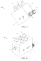
- FIG. 7 and FIG. 8 Another embodiment 10' of the present invention is as shown in FIG. 7 and FIG. 8 , which is a slight modification on the basis of the technical solution of the foregoing embodiment.
- the main differences are as follows.
- the two self-opening solenoid valves 1, 1 ⁇ of the first set of self-opening solenoid valves and the three self-opening solenoid valves 11, 11 ⁇ , 11 " of the second set of self-opening solenoid valves are all disposed on the same surface of the valve body 4, so that the self-opening solenoid valves 1, 1 ⁇ , 11, 11 ⁇ , 11" are more easily controlled.
- the gas inlet 5 is designed as a protrusive structure.
- the foregoing description is merely related to preferred embodiments of the present invention, and other embodiments may be obtained by modifying some technical features.
- the first nozzle, the second nozzle, the first set of self-opening solenoid valves, and the second set of self-opening solenoid valves are implemented in the foregoing embodiments because, generally, a small central fire cover and an outer ring fire cover of the burner are supplied with gas in current mainstream gas stoves.
- the application of the technical solution of the present invention is not limited to such a conventional mode. In the case that the burner is not divided into the small central fire cover and the outer ring fire cover but is supplied with gas in a uniform fashion, the technical solution of the present invention is also applicable.
- the technical solution of the present invention is still applicable.
- the control mode of the self-opening solenoid valves may be extended to more than two control modes such as opening and closing. Instead, the opening level may be adjusted continuously thereby implementing a more precise control of the gas supplying amount.
- the first nozzle and the second nozzle are supplied with the gas through the same gas inlet, i.e.
- the gas flowing in through the gas inlet passes through the first set of self-opening solenoid valves and the second set of self-opening solenoid valves respectively, and is then delivered to the first nozzle and the second nozzle.
- the number of the gas inlets may be set to two, and the two gas inlets are then used for supplying the first nozzle and the second nozzle with the gas, respectively.
- the number of the gas inlets may be adjusted accordingly to more than three inlets, and the more than three gas inlets are then used for supplying the corresponding set of self-opening solenoid valves and nozzle with the gas.
- the present invention further provides embodiments for a gas stove, which includes a base casing frame, pipelines, a panel, a cooker rack, a burner, an ignition device, and the gas valve device according to the foregoing embodiments.
Landscapes
- Engineering & Computer Science (AREA)
- Chemical & Material Sciences (AREA)
- Combustion & Propulsion (AREA)
- Mechanical Engineering (AREA)
- General Engineering & Computer Science (AREA)
- Feeding And Controlling Fuel (AREA)
Abstract
Description
- The present invention relates to the field of stoves and stove components, and more particularly to a gas valve device and a gas stove.
- Conventional gas valves include a flow control valve and a safety valve. During use, a gas stove can ignite only when the flow control valve and the safety valve are opened at the same time. Current safety valves mostly include a solenoid valve core, which is mounted on a rear end of the flow control valve. The flow control valve is opened by pressing down a rotation shaft and then rotating such that a cam mounted on the rotation shaft rotates and pushes aside the solenoid valve by means of a push rod. It can be seen that the conventional gas valve technology has the following two disadvantages. First, the safety valve and the flow control valve are implemented separately, hence the manufacturing cost is increased and the control precision is low. Second, the conventional gas valve is mainly controlled mechanically. Thus, on the one hand, the intelligent control level is low and user requirements of high-end and/or special users are not met, and on the other hand, the mechanical or semi-mechanical control mode may easily cause wear, thereby affecting the control precision and sensitivity, reducing the service life and having safety risks of gas leakage.
- In order to solve the foregoing technical problems, the present invention is directed to an electronically controlled gas valve device with long service life and a gas stove.
- Embodiments of the present invention provide a gas valve device, which includes at least one gas inlet, gas channel, and nozzle, wherein the gas inlet is in communication with a main gas pipe, one end of the gas channel is in communication with the gas inlet, the other end of the gas channel is in communication with the nozzle, the nozzle is used for supplying a burner with gas, a self-opening solenoid valve is arranged in the gas channel such that, when the self-opening solenoid valve is open, the gas flows to the nozzle through the self-opening solenoid valve, and when the self-opening solenoid valve is closed, the gas is not able to flow to the nozzle through the self-opening solenoid valve. The gas valve device further includes a control module, and the control module is implemented to control the self-opening solenoid valve.
- Preferably, the gas valve device, and in particular the self-opening solenoid valve, is provided with a thermocouple for closing the self-opening solenoid valve when accidental extinguishing of a fire is detected.
- Preferably, an adjustment unit is provided in the gas channel between the self-opening solenoid valve and the nozzle for adjusting a gas output flow.
- Preferably, the adjustment unit is an adjustment screw.
- Preferably, the gas valve device further includes a valve body, wherein the gas inlet is disposed on or at the valve body, the gas channel is disposed inside the valve. Mounting holes of the nozzle, the self-opening solenoid valve, and the adjustment unit are preferably realized in the valve body.
- Preferably, the valve is integrally formed. E.g. the valve body is a solid body.
- Preferably, the gas channel is a part of the structure of the valve body.
- Preferably, the valve device includes a first nozzle and a second nozzle, the first nozzle is used for supplying a small central fire cover of the burner with the gas, and the second nozzle is used for supplying an outer ring fire cover air-mixing chamber of the burner with the gas. A first set of self-opening solenoid valves and a second set of self-opening solenoid valves are provided, the first set of self-opening solenoid valves is used for controlling the gas flowing to the first nozzle, and the second set of self-opening solenoid valves is used for controlling the gas flowing to the second nozzle. The first set of self-opening solenoid valves includes more than one self-opening solenoid valves, and the gas passes through each of the self-opening solenoid valves of the first set of self-opening solenoid valves respectively, converges, and is delivered to the first nozzle. The second set of self-opening solenoid valves includes more than one self-opening solenoid valves, the gas passes through each of the self-opening solenoid valves of the second set of self-opening solenoid valves respectively, converges, and is delivered to the second nozzle.
- Preferably, the gas channel between the self-opening solenoid valves of the first set of self-opening solenoid valves and the first nozzle includes gas tributaries and a gas convergence channel, each of the gas tributaries corresponds to one of the self-opening solenoid valves of the first set of self-opening solenoid valves respectively, each of the gas tributaries is disposed with an adjustment unit respectively, one end of the gas convergence channel is in communication with each of the gas tributaries respectively, and the other end of the gas convergence channel is connected to the first nozzle. The gas channel between the self-opening solenoid valves of the second set of self-opening solenoid valves and the second nozzle includes gas tributaries and a gas convergence channel, each of the gas tributaries corresponds to one of the self-opening solenoid valves of the second set of self-opening solenoid valves respectively, each of the gas tributaries is disposed with an adjustment unit respectively, one end of the gas convergence channel is in communication with each of the gas tributaries respectively, and the other end of the gas convergence channel is connected to the second nozzle. The adjustment unit is an adjustment screw.
- Preferably, the number of the gas inlet is one.
- Preferably, the number of the gas inlets is two, and the two gas inlets are used for supplying the first nozzle and the second nozzle with gas, respectively.
- Preferably, the number of the self-opening solenoid valves of the second set of self-opening solenoid valves is greater than the number of the self-opening solenoid valves of the first set of self-opening solenoid valves.
- Preferably, the first set of self-opening solenoid valves includes two self-opening solenoid valves, and the second set of self-opening solenoid valves includes three self-opening solenoid valves.
- Preferably, the cross-sections of the gas tributary of a respective gas channel or set of solenoid valves are different in diameter.
- Preferably, both cross-sections of the two gas tributaries corresponding to the two self-opening solenoid valves of the first set of self-opening solenoid valves are round, and diameters of the cross-sections of the two gas tributaries are 1.5 mm and 1.2 mm, respectively.
- Preferably, all cross-sections of the three gas tributaries corresponding to the three self-opening solenoid valves of the second set of self-opening solenoid valves are round, and diameters of the cross-sections of the three gas tributaries are 1.8 mm, 1.5 mm, and 1.2 mm, respectively.
- Preferably, the first set of self-opening solenoid valves includes one self-opening solenoid valve, and the second set of self-opening solenoid valves includes two self-opening solenoid valves.
- Preferably, the first set of self-opening solenoid valves includes three self-opening solenoid valves, and the second set of self-opening solenoid valves includes five self-opening solenoid valves.
- Preferably, the control module includes a touch screen structure or device.
- Preferably, the control module includes a button structure or device.
- Preferably, the control module includes a knob structure or device.
- Preferably, the control module includes a wireless remote controller structure or device.
- Preferably, the control module includes an intelligent control unit, and the intelligent control unit has several pre-set modes for controlling the self-opening solenoid valves for an operator to choose.
- Preferably, the gas valve device, and in particular the control module, includes a sensor for detecting a cooking state, a gas content in the air, or a size of a flame for feeding back a detection result to the intelligent control unit; and the intelligent control unit controls the self-opening solenoid valves according to the information sent by the sensor.
- Preferably, the control module is also implemented to control an ignition device.
- Preferably, the number of the nozzles is greater than three; more than three sets of self-opening solenoid valves are included corresponding to each of the nozzles respectively for controlling the gas flowing to the corresponding nozzles; and each set of self-opening solenoid valves includes more than one self-opening solenoid valves.
- Preferably, the number of the gas inlets is greater than three, and each of the gas inlets corresponds to each set of self-opening solenoid valves and each of the nozzles respectively.
- The present invention further provides a gas stove comprising a base casing frame, pipelines, a panel, a cooker rack, a burner, an ignition device, and the gas valve device according to the foregoing description.
- The beneficial effects of embodiments of the present invention are as follows.
- 1. The mechanical or semi-mechanical gas control mode conventionally used in the field of gas stoves is changed, and the intelligent control level of the gas is improved.
- 2. Mechanical wear is reduced to a maximum extent, the safety risks are reduced while the service life of the gas valve device is increased.
- 3. The flow control valve and the safety valve are integrated, thereby reducing the manufacturing cost.
-
-
FIG. 1 is an exploded view of a valve device according to an embodiment of the present invention; -
FIG. 2 is a three-dimensional view of a valve device according to an embodiment of the present invention; -
FIG. 3 is another three-dimensional view of a valve device according to an embodiment of the present invention; -
FIG. 4 is a front view of a valve device according to an embodiment of the present invention; -
FIG. 5 is a sectional view along line A-A inFIG. 4 ; -
FIG. 6 is a schematic view of device of an embodiment of the present invention; -
FIG. 7 is a three-dimensional view of a valve device according to another embodiment of the present invention; and -
FIG. 8 is another three-dimensional view of a valve device according to another embodiment of the present invention. - The meanings of the reference numbers in the drawings are as follows: 1, 11 self-opening solenoid valve, 2, 12 adjustment screw, 3, 13 nozzle, 4 valve body, 5, 15 gas inlet, 6, 16 gas tributary, 7, 17 gas convergence channel, 8 control module, 9 connection, 10 valve device.
- In order to make the objectives, solutions, and beneficial effects of the present invention more comprehensible, the present invention is described further below with reference to the accompanying drawings and preferred embodiments.
- The present invention provides an embodiment of a
gas valve device 10 as shown inFIG. 1 to FIG. 6 , which includes agas inlet 5, a gas channel, and at least onenozzle 3. Thegas inlet 5 is in communication with a main gas pipe that delivers gas to thegas inlet 5, one end of the gas channel is in communication with thegas inlet 5, the other end of the gas channel is in communication with thenozzle 3, the gas flowing in through thegas inlet 5 is delivered to thenozzle 3 through the gas channel, and thenozzle 3 is used for supplying a burner with the gas. The device includes afirst nozzle 3 and asecond nozzle 13, thefirst nozzle 3 is used for supplying a small central fire cover of the burner with the gas, and thesecond nozzle 13 is used for supplying an outer ring fire cover air-mixing chamber of the burner with the gas. Two sets of self-opening solenoid valves, namely, a first set of self-openingsolenoid valves 1, 1' and a second set of self-openingsolenoid valves solenoid valves 1, 1' is used for controlling the gas flowing to thefirst nozzle 3, and the second set of self-openingsolenoid valves second nozzle 13. The first set of self-opening solenoid valves includes two self-openingsolenoid valves 1, 1', and the gas passes through each of the two self-openingsolenoid valves 1, 1' respectively, converges, and is delivered to thefirst nozzle 3. The second set of self-opening solenoid valves includes three self-openingsolenoid valves solenoid valves second nozzle 13. - The gas channel between the two self-opening
solenoid valves 1, 1' of the first set of self-opening solenoid valves and thefirst nozzle 3 includes at least two gas tributaries 6, 6' and at least onegas convergence channel 7, and each of the gas tributaries 6, 6' corresponds to each of the two self-openingsolenoid valves 1, 1' of the first set of self-opening solenoid valves, respectively. Both cross-sections of the two gas tributaries 6, 6' are round, but the diameters of the two circles are different, which are 1.5 mm and 1.2 mm, respectively. Since the diameters of the cross-sections are different, gas delivery efficiencies of the two gas tributaries 6, 6' are different. The larger the diameter the more gas is delivered per time unit. The two gas tributaries 6, 6' are respectively disposed with twoadjustment units 2, 2', one end of thegas convergence channel 7 is in communication with the two gas tributaries 6, 6', respectively, and the other end of thegas convergence channel 7 is in communication with thefirst nozzle 3. When the two self-openingsolenoid valves 1, 1' of the first set of self-opening solenoid valves are closed, no gas flows into the two gas tributaries 6, 6', and no gas flows out from thefirst nozzle 3. When one self-openingsolenoid valve 1 is open, the gas passes through the self-openingsolenoid valve 1, flows into the corresponding gas tributary 6, further flows into thegas convergence channel 7, and then flows out from thefirst nozzle 3. When the other self-opening solenoid valve 1' is also open, the gas flows into the corresponding gas tributary 6', further flows into thegas convergence channel 7, and then flows out from thefirst nozzle 3. It can be seen that, by controlling the two self-openingsolenoid valves 1,1' of the first set of the self-opening solenoid valves, not only the opening and closing of the gas but also the gas supplying amount can be controlled. - The gas channel between the three self-opening
solenoid valves second nozzle 13 includes threegas tributaries gas convergence channel 17, and each of thegas tributaries solenoid valves gas tributaries gas tributaries gas tributaries adjustment units gas convergence channel 17 is in communication with the threegas tributaries gas convergence channel 17 is in communication with thesecond nozzle 13. The operating principle of the second set of the self-opening solenoid valves is the same as that of the first set of the self-opening solenoid valves, through which not only the opening and closing of the gas but also the gas supplying amount can be controlled. - It should be noted that, the assigned number of self-opening
solenoid valves solenoid valves solenoid valves 1, 1ʹ in the first set of self-opening solenoid valves. For example, one self-opening solenoid valve may be set in the first set of self-opening solenoid valves, and two self-opening solenoid valves may be set in the second set of self-opening solenoid valves. For another example, three self-opening solenoid valves may be set in the first set of self-opening solenoid valves, and five self-opening solenoid valves may be set in the second set of self-opening solenoid valves. - In contrast to solenoid valves used in conventional safety valve arrangements that require to be opened under the action of an external mechanical force, the self-opening
solenoid valves solenoid valves 1, 1ʹ, 11, 11ʹ, 11ʺ can be disposed with a charging circuit, a discharge circuit, and a holding circuit. Before the operation starts, an external power source first charges a capacitor in the charging circuit, and at an instant when the operation starts, the fully charged capacitor begins to discharge, so that a load voltage on a coil of the self-opening solenoid valve instantly reaches a high value, and then the self-opening solenoid valve is opened by using an instant electromagnetic force generated by the voltage. During normal operation, the voltage generated by a thermocouple is fed to the self-opening solenoid valve through the holding circuit, so that the self-opening solenoid valve is maintained in an open state. - When a respective self-opening
solenoid valve 1, 1ʹ, 11, 11ʹ, 11ʺ is open, the gas flows to therespective nozzle solenoid valve 1, 1ʹ, 11, 11ʹ, 11ʺ; and when the self-openingsolenoid valve 1, 1ʹ, 11, 11ʹ, 11ʺ is closed, the gas is not able to flow to thenozzle solenoid valve 1, 1ʹ, 11, 11ʹ, 11ʺ. The opening and closing of the self-openingsolenoid valves 1, 1ʹ, 11, 11ʹ, 11" is controlled by acontrol module 8 coupled to thevalves 1', 11, 11ʹ, 11" by aline 9. The self-opening solenoid valves, 1ʹ, 11, 11ʹ, 11" can be provided with a thermocouple for closing the self-openingsolenoid valve 1, 1ʹ, 11, 11ʹ, 11" when accidental extinguishing of a fire is detected, so as to prevent a user from being poisoned by the gas. It can be seen that, the respective self-openingsolenoid valve 1, 1ʹ, 11, 11ʹ, 11" is a flow control valve as well as a safety valve. Arespective adjustment unit solenoid valves 1, 1ʹ, 11, 11ʹ, 11" and thenozzle - As shown in the figures, this embodiment of the
gas valve device 10 further includes asolid valve body 4, and thevalve body 4 is integrally formed. Thegas inlet 5 is disposed at or on thevalve body 4, thegas channel valve body 4, the gas channel is a part of the structure of thevalve body 4, and mounting holes for thenozzles solenoid valves 1, 1ʹ, 11, 11ʹ, 11ʺ, and theadjustment units 2, 2ʹ, 12, 12ʹ, 12" are arranged inside of thevalve body 4, respectively. Thevalve body 4 used in this embodiment is approximately cuboid-shaped, but is not limited to such a shape in the actual application. Thevalve body 4 may be adjusted according to the requirements for the actual use. For example, thevalve 4 may also have a shape of a cube, a sphere, a cone, a cylinder, an irregular body, or other shapes. - As shown in
FIG. 6 , thegas valve device 10 further includes acontrol module 8 for controlling the self-openingsolenoid valve 1. Thecontrol module 8 may include various different structures, and may specifically comprise a touch screen device, a button device, a knob device, or a wireless remote controller device. For example, when thecontrol module 8 includes a button device, a microprocessor control unit (MCU) can be used to preset three levels of power, namely, high, medium and low, or more levels of power for the user to self-adjust. Further, a fine adjustment function can be implemented, so as to enable the user to perform fine adjustments among the levels. As another example, thecontrol module 8 may employ a continous adjustment mode similar to that used in electromagnetic cookers, so that the user can steplessly adjust the power of the flame. - In addition, the
control module 8 may further implement an intelligent control mode. Specifically, thecontrol module 8 can include an intelligent control unit, wherein the intelligent control unit has several pre-set modes for controlling the self-openingsolenoid valves 1, 1ʹ, 11, 11ʹ, 11" for an operator to choose. Preferably, thecontrol module 8 is further provided or coupled with/to a sensor for detecting a cooking state, a gas content in the air, or a size of a flame, wherein a detection result is sent to the intelligent control unit; and the intelligent control unit controls the self-openingsolenoid valves 1, 1ʹ, 11, 11ʹ, 11ʺ according to the information sent by the sensor. - The
control module 8 may also be implemented to control an ignition device. - Although the ignition device is not a part of the
gas valve device 10, thecontrol module 8 may be used for controlling thegas valve device 10 and the ignition device at the same time, thereby reducing the cost on the one hand, and improving the control efficiency on the other hand. - Another
embodiment 10' of the present invention is as shown inFIG. 7 and FIG. 8 , which is a slight modification on the basis of the technical solution of the foregoing embodiment. The main differences are as follows. First, the two self-openingsolenoid valves 1, 1ʹ of the first set of self-opening solenoid valves and the three self-openingsolenoid valves 11, 11ʹ, 11 " of the second set of self-opening solenoid valves are all disposed on the same surface of thevalve body 4, so that the self-openingsolenoid valves 1, 1ʹ, 11, 11ʹ, 11" are more easily controlled. Second, thegas inlet 5 is designed as a protrusive structure. - The foregoing description is merely related to preferred embodiments of the present invention, and other embodiments may be obtained by modifying some technical features. For example, the first nozzle, the second nozzle, the first set of self-opening solenoid valves, and the second set of self-opening solenoid valves are implemented in the foregoing embodiments because, generally, a small central fire cover and an outer ring fire cover of the burner are supplied with gas in current mainstream gas stoves. However, the application of the technical solution of the present invention is not limited to such a conventional mode. In the case that the burner is not divided into the small central fire cover and the outer ring fire cover but is supplied with gas in a uniform fashion, the technical solution of the present invention is also applicable. When the burner adopts a more complicated gas supply mode, e.g. the burner is divided into more than three different areas for respective gas supply, the technical solution of the present invention is still applicable. As another example, the control mode of the self-opening solenoid valves may be extended to more than two control modes such as opening and closing. Instead, the opening level may be adjusted continuously thereby implementing a more precise control of the gas supplying amount. According to another example, in the foregoing embodiments, the first nozzle and the second nozzle are supplied with the gas through the same gas inlet, i.e. the gas flowing in through the gas inlet passes through the first set of self-opening solenoid valves and the second set of self-opening solenoid valves respectively, and is then delivered to the first nozzle and the second nozzle. Alternatively, the number of the gas inlets may be set to two, and the two gas inlets are then used for supplying the first nozzle and the second nozzle with the gas, respectively. When the burner is divided into more than three different areas for a respective gas supply, the number of the gas inlets may be adjusted accordingly to more than three inlets, and the more than three gas inlets are then used for supplying the corresponding set of self-opening solenoid valves and nozzle with the gas.
- The present invention further provides embodiments for a gas stove, which includes a base casing frame, pipelines, a panel, a cooker rack, a burner, an ignition device, and the gas valve device according to the foregoing embodiments.
- It should be noted that, the present invention should not be construed as being limited to the implementation described above, but should be construed as covering all possible implementation situations determined from the claims in combination with the disclosure of the specification of the present invention.
Claims (15)
- A gas valve device (10) comprising
at least one gas inlet (5), gas channel, and nozzle (3), wherein the gas inlet (5) is in communication with a main gas pipe, one end of the gas channel is in communication with the gas inlet (5), the other end of the gas channel is in communication with the nozzle (3), and the nozzle (3) is used for supplying a burner with gas, wherein:a self-opening solenoid valve (1) is arranged in the gas channel such that, when the self-opening solenoid valve (1) is open, the gas flows to the nozzle (3) through the self-opening solenoid valve (3), and when the self-opening solenoid valve (3) is closed, the gas is not able to flow to the nozzle (3) through the self-opening solenoid valve (3); and whereinthe gas valve device (10) further comprises a control module (8) for controlling the self-opening solenoid valve (1). - The gas valve device (10) according to claim 1, further comprising a thermocouple for closing the self-opening solenoid valve (1) when accidental extinguishing of a fire is detected.
- The gas valve device (10) according to claim 1 or 2, further comprising an adjustment unit (2) disposed in the gas channel between the self-opening solenoid valve (1) and the nozzle (3) for adjusting a gas output flow.
- The gas valve device (10) according to any one of claims 1 - 3, further comprising a valve body (4),
wherein the gas inlet (5) is disposed at the valve body (4), and the gas channel (7) is disposed inside the valve body (4), and
wherein mounting holes for the nozzle (3), the self-opening solenoid valve (1), and/or the adjustment unit (2) are arranged in or at the valve body (4). - The gas valve device (10) according to any one of claims 1 - 4, comprising
a first nozzle (3) for supplying a small central fire cover of the burner with gas, and a second nozzle (13) for supplying an outer ring fire cover air-mixing chamber of the burner with gas,
wherein a first set of self-opening solenoid valves (1, 1') is provided for controlling the gas flowing to the first nozzle (3), and a second set of self-opening solenoid valves (11, 11ʹ, 11 ") is provided for controlling the gas flowing to the second nozzle (13),
wherein the first set of self-opening solenoid valves comprises at least two self-opening solenoid valves (1, 1') arranged such that the gas passes through each of the self-opening solenoid valves (1, 1') of the first set of self-opening solenoid valves, converges, and is delivered to the first nozzle (3); and
wherein the second set of self-opening solenoid valves comprises at least two self-opening solenoid valves (11, 11ʹ, 11ʺ) arranged such that the gas passes through each of the self-opening solenoid valves (11, 11ʹ, 11ʺ) of the second set of self-opening solenoid valves, converges, and is delivered to the second nozzle (13). - The gas valve device (10) according to claim 5, characterized in that
a gas channel between the self-opening solenoid valves (1, 1ʹ) of the first set of self-open solenoid valves and the first nozzle comprises gas tributaries (6, 6') and a gas convergence channel (7), each of the gas tributaries (6, 6') corresponds to one of the self-opening solenoid valves (1, 1ʹ) of the first set of self-opening solenoid valves, and each of the gas tributaries (6, 6') is provided with an adjustment unit (2, 2'), one end of the gas convergence channel (7) is in communication with each of the gas tributaries (6, 6'), and the other end of the gas convergence channel (7) is connected to the first nozzle (3); and
a gas channel between the self-opening solenoid valves (11, 11ʹ, 11ʺ) of the second set of self-opening solenoid valves and the second nozzle (13) comprises gas tributaries (16, 16,', 16") and a gas convergence channel (17), each of the gas tributaries (16, 16', 16") corresponds to one of the self-open solenoid valves (11, 11ʹ, 11ʺ) of the second set of self-open solenoid valves, each of the gas tributaries (16, 16ʹ, 16") is provided with an adjustment unit (12, 12ʹ, 12"), one end of the gas convergence channel (17) is in communication with each of the gas tributaries (16, 16ʹ, 16ʺ), and the other end of the gas convergence channel (17) is connected to the second nozzle (13). - The gas valve device (10) according to claim 3 or 6, characterized in that the adjustment unit (2, 2ʹ, 12, 12ʹ, 12ʺ) is an adjustment screw.
- The gas valve device (10) according to any one of claims 5 - 7, characterized in that the number of the gas inlets (5) is two, and the two gas inlets are used for independently supplying the first nozzle (3) with gas and the second nozzle (13) with the gas.
- The gas valve device (10) according to claim any one of claims 5 - 8, characterized in that the number of the self-opening solenoid valves (11, 11ʹ, 11ʺ) of the second set of self-opening solenoid valves is greater than the number of the self-opening solenoid valves (1, 1ʹ) of the first set of self-opening solenoid valves.
- The gas valve device (10) according to any one of claims 6 - 9, characterized in that the cross-sections of the gas tributaries (6, 6ʹ, 16, 16ʺ, 16") corresponding to the self-opening solenoid valves (1, 1,ʹ, 11, 11ʹ, 11ʺ) of the first set and/or the second set of self-opening solenoid valves are round, and the gas tributaries (6, 6ʹ, 16, 16ʹ, 16") of at least one set have different cross-section diameters.
- The gas valve device (10) according to any one of claims 1 - 10, characterized in that the control module (8) includes at least one of the group of: a touch screen device, a button device, a knob device, a wireless remote controller device, and/or an intelligent control unit for controlling the self-open solenoid valves according to several pre-set modes according to an operator's input.
- The gas valve device (10) according to any one of claims 1-11, further comprising a sensor for detecting a cooking state, a gas content in the air, and/or a size of a flame, and for providing a detection result to the control unit (8), wherein the control unit (8) is implemented to control the self-opening solenoid valves as a function of the detection result.
- The gas valve device (10) according to any one of claims 1-12, characterized in that the control module (8) is implemented to control an ignition device.
- The gas valve device (10) according to any one of claims 1-13, characterized in that
the number of the nozzles (3, 13) and/or inlets (5) is greater than three;
the gas valve device (10) includes more than three sets of self-opening solenoid valves, wherein each set corresponds to one of the nozzles (3, 13) for controlling the gas flowing to the corresponding nozzle (3, 13); and wherein
each set of self-opening solenoid valves comprises at least two self-opening solenoid valves (1, 1ʹ, 11, 11ʹ, 11ʺ). - A gas stove, comprising a base casing frame, pipelines, a panel, a cooker rack, a burner, an ignition device, and a gas valve device (10) according to any one of claims 1 to 14.
Applications Claiming Priority (1)
| Application Number | Priority Date | Filing Date | Title |
|---|---|---|---|
| CN201010232653.4A CN102338233B (en) | 2010-07-16 | 2010-07-16 | Gas valve device and the gas cooker with this kind of gas valve device |
Publications (3)
| Publication Number | Publication Date |
|---|---|
| EP2407721A2 true EP2407721A2 (en) | 2012-01-18 |
| EP2407721A3 EP2407721A3 (en) | 2017-09-13 |
| EP2407721B1 EP2407721B1 (en) | 2019-04-24 |
Family
ID=45065565
Family Applications (1)
| Application Number | Title | Priority Date | Filing Date |
|---|---|---|---|
| EP11173502.3A Active EP2407721B1 (en) | 2010-07-16 | 2011-07-11 | Gas valve device and gas stove |
Country Status (4)
| Country | Link |
|---|---|
| EP (1) | EP2407721B1 (en) |
| CN (1) | CN102338233B (en) |
| ES (1) | ES2724711T3 (en) |
| TR (1) | TR201907510T4 (en) |
Cited By (5)
| Publication number | Priority date | Publication date | Assignee | Title |
|---|---|---|---|---|
| CN103115168A (en) * | 2013-03-04 | 2013-05-22 | 广州祈信金属制品有限公司 | Dual-purpose gas plug conversion valve |
| WO2014091379A1 (en) * | 2012-12-13 | 2014-06-19 | BSH Bosch und Siemens Hausgeräte GmbH | Valve for a gas cooker |
| CN105650693A (en) * | 2016-03-30 | 2016-06-08 | 广东万和电气有限公司 | Self-adaptive gas stove and control method thereof |
| CN106931434A (en) * | 2015-12-29 | 2017-07-07 | 浙江苏泊尔家电制造有限公司 | Burner |
| CN113266686A (en) * | 2021-04-03 | 2021-08-17 | 广东重尚美物联科技有限公司 | Gas valve capable of being started in emergency |
Families Citing this family (7)
| Publication number | Priority date | Publication date | Assignee | Title |
|---|---|---|---|---|
| CN103292365A (en) * | 2012-02-23 | 2013-09-11 | 金元革 | Multifunctional valve |
| CN102679018B (en) * | 2012-05-07 | 2013-08-28 | 东莞市正幸电器有限公司 | Solenoid valve for gas stove |
| CN103453560B (en) * | 2012-05-28 | 2018-07-10 | 博西华电器(江苏)有限公司 | Gas-cooker and its gas flow control device and method |
| CN102759105B (en) * | 2012-07-03 | 2014-10-01 | 海盐法狮龙建材科技有限公司 | Adjustable gas nozzle |
| CN104482569A (en) * | 2014-11-27 | 2015-04-01 | 谢启标 | Gas cooker capable of continuously regulating firepower |
| CN106151631B (en) * | 2016-08-10 | 2018-03-27 | 山东美迪宇能医疗科技股份有限公司 | A kind of multi-path flow control valve |
| CN110657271A (en) * | 2019-04-19 | 2020-01-07 | 宁波丽辰电器有限公司 | Combined gas valve with multiple gas outlet channels |
Family Cites Families (9)
| Publication number | Priority date | Publication date | Assignee | Title |
|---|---|---|---|---|
| JPS59221516A (en) * | 1983-05-31 | 1984-12-13 | Matsushita Electric Ind Co Ltd | Gas stove |
| GB2230595B (en) * | 1989-04-08 | 1993-05-12 | Pompe Dev Ltd | Gas hob |
| CN1411543A (en) * | 1999-10-18 | 2003-04-16 | 肯普阀公司 | Electronic gas cooktop control with system and method thereof |
| CN2456052Y (en) * | 2000-11-17 | 2001-10-24 | 郑少添 | Gas burner |
| JP4137571B2 (en) * | 2002-09-26 | 2008-08-20 | リンナイ株式会社 | Gas outlet |
| US20060213496A1 (en) * | 2005-03-24 | 2006-09-28 | Robershaw Controls Company | Multiple-output solenoid valve |
| CN101078529B (en) * | 2006-05-25 | 2010-10-13 | 杭州电子科技大学 | Embedded type control system for domestic gas oven |
| CN201196278Y (en) * | 2008-05-23 | 2009-02-18 | 金鹤 | Gas control valve |
| CN201448884U (en) * | 2009-05-25 | 2010-05-05 | 广东万和新电气股份有限公司 | Electrical-control gas stove utilizing given-proportion adjustment |
-
2010
- 2010-07-16 CN CN201010232653.4A patent/CN102338233B/en not_active Expired - Fee Related
-
2011
- 2011-07-11 EP EP11173502.3A patent/EP2407721B1/en active Active
- 2011-07-11 ES ES11173502T patent/ES2724711T3/en active Active
- 2011-07-11 TR TR2019/07510T patent/TR201907510T4/en unknown
Non-Patent Citations (1)
| Title |
|---|
| None |
Cited By (6)
| Publication number | Priority date | Publication date | Assignee | Title |
|---|---|---|---|---|
| WO2014091379A1 (en) * | 2012-12-13 | 2014-06-19 | BSH Bosch und Siemens Hausgeräte GmbH | Valve for a gas cooker |
| CN103115168A (en) * | 2013-03-04 | 2013-05-22 | 广州祈信金属制品有限公司 | Dual-purpose gas plug conversion valve |
| CN103115168B (en) * | 2013-03-04 | 2015-09-23 | 广州祈信金属制品有限公司 | A kind of dual-purpose Gas cock conversion valve |
| CN106931434A (en) * | 2015-12-29 | 2017-07-07 | 浙江苏泊尔家电制造有限公司 | Burner |
| CN105650693A (en) * | 2016-03-30 | 2016-06-08 | 广东万和电气有限公司 | Self-adaptive gas stove and control method thereof |
| CN113266686A (en) * | 2021-04-03 | 2021-08-17 | 广东重尚美物联科技有限公司 | Gas valve capable of being started in emergency |
Also Published As
| Publication number | Publication date |
|---|---|
| TR201907510T4 (en) | 2019-07-22 |
| EP2407721B1 (en) | 2019-04-24 |
| CN102338233B (en) | 2015-08-26 |
| EP2407721A3 (en) | 2017-09-13 |
| CN102338233A (en) | 2012-02-01 |
| ES2724711T3 (en) | 2019-09-13 |
Similar Documents
| Publication | Publication Date | Title |
|---|---|---|
| EP2407721B1 (en) | Gas valve device and gas stove | |
| CN103876646A (en) | Gas oven | |
| KR100691563B1 (en) | Gas range | |
| KR101921733B1 (en) | Electric burner control device for gas range | |
| CN104913302B (en) | Safety-type dual gas supply control system | |
| CN208417617U (en) | Gas valve capable of linearly adjusting firepower and gas stove | |
| CN112032358A (en) | Gas stove regulating valve and gas stove | |
| CN208431761U (en) | A kind of adjustable upward-air-feeding type stove combustor | |
| CN210123165U (en) | Gas stove with pressure feedback system | |
| CN211041044U (en) | Gas stove with central fire controlled independently | |
| US11655976B2 (en) | Gas burner arrangement and household cooking appliance | |
| CN209295207U (en) | A kind of fuel gas energy-saving equipment by increasing fuel gas flow gap | |
| CN210219880U (en) | Wind-driven integrated stove | |
| CN211175495U (en) | Gas stove regulating valve and gas stove | |
| CN207849447U (en) | A kind of intelligent stove | |
| CN214198788U (en) | Gas control valve and gas stove | |
| KR200414662Y1 (en) | Gas range | |
| CN209263084U (en) | A kind of Novel igniter | |
| CN216409048U (en) | Gas stove | |
| CN215982694U (en) | Combustion mechanism of integrated kitchen and integrated kitchen | |
| CN110206915A (en) | Gas valve capable of linearly adjusting firepower and gas stove | |
| CN217927290U (en) | Plug valve and stove | |
| CN220083068U (en) | Air inlet seat capable of adjusting firepower, combustor and gas stove | |
| CN215808677U (en) | Cooking range system | |
| CN114483990B (en) | Plug valve and gas stove |
Legal Events
| Date | Code | Title | Description |
|---|---|---|---|
| AK | Designated contracting states |
Kind code of ref document: A2 Designated state(s): AL AT BE BG CH CY CZ DE DK EE ES FI FR GB GR HR HU IE IS IT LI LT LU LV MC MK MT NL NO PL PT RO RS SE SI SK SM TR |
|
| AX | Request for extension of the european patent |
Extension state: BA ME |
|
| PUAI | Public reference made under article 153(3) epc to a published international application that has entered the european phase |
Free format text: ORIGINAL CODE: 0009012 |
|
| RAP1 | Party data changed (applicant data changed or rights of an application transferred) |
Owner name: BSH HAUSGERAETE GMBH |
|
| PUAL | Search report despatched |
Free format text: ORIGINAL CODE: 0009013 |
|
| AK | Designated contracting states |
Kind code of ref document: A3 Designated state(s): AL AT BE BG CH CY CZ DE DK EE ES FI FR GB GR HR HU IE IS IT LI LT LU LV MC MK MT NL NO PL PT RO RS SE SI SK SM TR |
|
| AX | Request for extension of the european patent |
Extension state: BA ME |
|
| RIC1 | Information provided on ipc code assigned before grant |
Ipc: F24C 3/12 20060101AFI20170809BHEP |
|
| STAA | Information on the status of an ep patent application or granted ep patent |
Free format text: STATUS: REQUEST FOR EXAMINATION WAS MADE |
|
| 17P | Request for examination filed |
Effective date: 20180313 |
|
| RBV | Designated contracting states (corrected) |
Designated state(s): AL AT BE BG CH CY CZ DE DK EE ES FI FR GB GR HR HU IE IS IT LI LT LU LV MC MK MT NL NO PL PT RO RS SE SI SK SM TR |
|
| GRAP | Despatch of communication of intention to grant a patent |
Free format text: ORIGINAL CODE: EPIDOSNIGR1 |
|
| STAA | Information on the status of an ep patent application or granted ep patent |
Free format text: STATUS: GRANT OF PATENT IS INTENDED |
|
| INTG | Intention to grant announced |
Effective date: 20181206 |
|
| GRAS | Grant fee paid |
Free format text: ORIGINAL CODE: EPIDOSNIGR3 |
|
| GRAA | (expected) grant |
Free format text: ORIGINAL CODE: 0009210 |
|
| STAA | Information on the status of an ep patent application or granted ep patent |
Free format text: STATUS: THE PATENT HAS BEEN GRANTED |
|
| AK | Designated contracting states |
Kind code of ref document: B1 Designated state(s): AL AT BE BG CH CY CZ DE DK EE ES FI FR GB GR HR HU IE IS IT LI LT LU LV MC MK MT NL NO PL PT RO RS SE SI SK SM TR |
|
| REG | Reference to a national code |
Ref country code: GB Ref legal event code: FG4D |
|
| REG | Reference to a national code |
Ref country code: CH Ref legal event code: EP |
|
| REG | Reference to a national code |
Ref country code: AT Ref legal event code: REF Ref document number: 1124600 Country of ref document: AT Kind code of ref document: T Effective date: 20190515 Ref country code: IE Ref legal event code: FG4D |
|
| REG | Reference to a national code |
Ref country code: DE Ref legal event code: R096 Ref document number: 602011058266 Country of ref document: DE |
|
| REG | Reference to a national code |
Ref country code: NL Ref legal event code: MP Effective date: 20190424 |
|
| REG | Reference to a national code |
Ref country code: LT Ref legal event code: MG4D |
|
| REG | Reference to a national code |
Ref country code: ES Ref legal event code: FG2A Ref document number: 2724711 Country of ref document: ES Kind code of ref document: T3 Effective date: 20190913 |
|
| PG25 | Lapsed in a contracting state [announced via postgrant information from national office to epo] |
Ref country code: NL Free format text: LAPSE BECAUSE OF FAILURE TO SUBMIT A TRANSLATION OF THE DESCRIPTION OR TO PAY THE FEE WITHIN THE PRESCRIBED TIME-LIMIT Effective date: 20190424 |
|
| PG25 | Lapsed in a contracting state [announced via postgrant information from national office to epo] |
Ref country code: LT Free format text: LAPSE BECAUSE OF FAILURE TO SUBMIT A TRANSLATION OF THE DESCRIPTION OR TO PAY THE FEE WITHIN THE PRESCRIBED TIME-LIMIT Effective date: 20190424 Ref country code: HR Free format text: LAPSE BECAUSE OF FAILURE TO SUBMIT A TRANSLATION OF THE DESCRIPTION OR TO PAY THE FEE WITHIN THE PRESCRIBED TIME-LIMIT Effective date: 20190424 Ref country code: SE Free format text: LAPSE BECAUSE OF FAILURE TO SUBMIT A TRANSLATION OF THE DESCRIPTION OR TO PAY THE FEE WITHIN THE PRESCRIBED TIME-LIMIT Effective date: 20190424 Ref country code: FI Free format text: LAPSE BECAUSE OF FAILURE TO SUBMIT A TRANSLATION OF THE DESCRIPTION OR TO PAY THE FEE WITHIN THE PRESCRIBED TIME-LIMIT Effective date: 20190424 Ref country code: NO Free format text: LAPSE BECAUSE OF FAILURE TO SUBMIT A TRANSLATION OF THE DESCRIPTION OR TO PAY THE FEE WITHIN THE PRESCRIBED TIME-LIMIT Effective date: 20190724 Ref country code: PT Free format text: LAPSE BECAUSE OF FAILURE TO SUBMIT A TRANSLATION OF THE DESCRIPTION OR TO PAY THE FEE WITHIN THE PRESCRIBED TIME-LIMIT Effective date: 20190824 Ref country code: AL Free format text: LAPSE BECAUSE OF FAILURE TO SUBMIT A TRANSLATION OF THE DESCRIPTION OR TO PAY THE FEE WITHIN THE PRESCRIBED TIME-LIMIT Effective date: 20190424 |
|
| PG25 | Lapsed in a contracting state [announced via postgrant information from national office to epo] |
Ref country code: RS Free format text: LAPSE BECAUSE OF FAILURE TO SUBMIT A TRANSLATION OF THE DESCRIPTION OR TO PAY THE FEE WITHIN THE PRESCRIBED TIME-LIMIT Effective date: 20190424 Ref country code: PL Free format text: LAPSE BECAUSE OF FAILURE TO SUBMIT A TRANSLATION OF THE DESCRIPTION OR TO PAY THE FEE WITHIN THE PRESCRIBED TIME-LIMIT Effective date: 20190424 Ref country code: LV Free format text: LAPSE BECAUSE OF FAILURE TO SUBMIT A TRANSLATION OF THE DESCRIPTION OR TO PAY THE FEE WITHIN THE PRESCRIBED TIME-LIMIT Effective date: 20190424 Ref country code: BG Free format text: LAPSE BECAUSE OF FAILURE TO SUBMIT A TRANSLATION OF THE DESCRIPTION OR TO PAY THE FEE WITHIN THE PRESCRIBED TIME-LIMIT Effective date: 20190724 Ref country code: GR Free format text: LAPSE BECAUSE OF FAILURE TO SUBMIT A TRANSLATION OF THE DESCRIPTION OR TO PAY THE FEE WITHIN THE PRESCRIBED TIME-LIMIT Effective date: 20190725 |
|
| REG | Reference to a national code |
Ref country code: AT Ref legal event code: MK05 Ref document number: 1124600 Country of ref document: AT Kind code of ref document: T Effective date: 20190424 |
|
| PG25 | Lapsed in a contracting state [announced via postgrant information from national office to epo] |
Ref country code: IS Free format text: LAPSE BECAUSE OF FAILURE TO SUBMIT A TRANSLATION OF THE DESCRIPTION OR TO PAY THE FEE WITHIN THE PRESCRIBED TIME-LIMIT Effective date: 20190824 |
|
| REG | Reference to a national code |
Ref country code: DE Ref legal event code: R097 Ref document number: 602011058266 Country of ref document: DE |
|
| PG25 | Lapsed in a contracting state [announced via postgrant information from national office to epo] |
Ref country code: CZ Free format text: LAPSE BECAUSE OF FAILURE TO SUBMIT A TRANSLATION OF THE DESCRIPTION OR TO PAY THE FEE WITHIN THE PRESCRIBED TIME-LIMIT Effective date: 20190424 Ref country code: SK Free format text: LAPSE BECAUSE OF FAILURE TO SUBMIT A TRANSLATION OF THE DESCRIPTION OR TO PAY THE FEE WITHIN THE PRESCRIBED TIME-LIMIT Effective date: 20190424 Ref country code: EE Free format text: LAPSE BECAUSE OF FAILURE TO SUBMIT A TRANSLATION OF THE DESCRIPTION OR TO PAY THE FEE WITHIN THE PRESCRIBED TIME-LIMIT Effective date: 20190424 Ref country code: DK Free format text: LAPSE BECAUSE OF FAILURE TO SUBMIT A TRANSLATION OF THE DESCRIPTION OR TO PAY THE FEE WITHIN THE PRESCRIBED TIME-LIMIT Effective date: 20190424 Ref country code: RO Free format text: LAPSE BECAUSE OF FAILURE TO SUBMIT A TRANSLATION OF THE DESCRIPTION OR TO PAY THE FEE WITHIN THE PRESCRIBED TIME-LIMIT Effective date: 20190424 Ref country code: AT Free format text: LAPSE BECAUSE OF FAILURE TO SUBMIT A TRANSLATION OF THE DESCRIPTION OR TO PAY THE FEE WITHIN THE PRESCRIBED TIME-LIMIT Effective date: 20190424 |
|
| PG25 | Lapsed in a contracting state [announced via postgrant information from national office to epo] |
Ref country code: MC Free format text: LAPSE BECAUSE OF FAILURE TO SUBMIT A TRANSLATION OF THE DESCRIPTION OR TO PAY THE FEE WITHIN THE PRESCRIBED TIME-LIMIT Effective date: 20190424 Ref country code: SM Free format text: LAPSE BECAUSE OF FAILURE TO SUBMIT A TRANSLATION OF THE DESCRIPTION OR TO PAY THE FEE WITHIN THE PRESCRIBED TIME-LIMIT Effective date: 20190424 |
|
| PLBE | No opposition filed within time limit |
Free format text: ORIGINAL CODE: 0009261 |
|
| REG | Reference to a national code |
Ref country code: CH Ref legal event code: PL |
|
| STAA | Information on the status of an ep patent application or granted ep patent |
Free format text: STATUS: NO OPPOSITION FILED WITHIN TIME LIMIT |
|
| GBPC | Gb: european patent ceased through non-payment of renewal fee |
Effective date: 20190724 |
|
| 26N | No opposition filed |
Effective date: 20200127 |
|
| REG | Reference to a national code |
Ref country code: BE Ref legal event code: MM Effective date: 20190731 |
|
| PG25 | Lapsed in a contracting state [announced via postgrant information from national office to epo] |
Ref country code: GB Free format text: LAPSE BECAUSE OF NON-PAYMENT OF DUE FEES Effective date: 20190724 |
|
| PG25 | Lapsed in a contracting state [announced via postgrant information from national office to epo] |
Ref country code: BE Free format text: LAPSE BECAUSE OF NON-PAYMENT OF DUE FEES Effective date: 20190731 Ref country code: LU Free format text: LAPSE BECAUSE OF NON-PAYMENT OF DUE FEES Effective date: 20190711 Ref country code: CH Free format text: LAPSE BECAUSE OF NON-PAYMENT OF DUE FEES Effective date: 20190731 Ref country code: SI Free format text: LAPSE BECAUSE OF FAILURE TO SUBMIT A TRANSLATION OF THE DESCRIPTION OR TO PAY THE FEE WITHIN THE PRESCRIBED TIME-LIMIT Effective date: 20190424 Ref country code: LI Free format text: LAPSE BECAUSE OF NON-PAYMENT OF DUE FEES Effective date: 20190731 |
|
| PG25 | Lapsed in a contracting state [announced via postgrant information from national office to epo] |
Ref country code: FR Free format text: LAPSE BECAUSE OF NON-PAYMENT OF DUE FEES Effective date: 20190731 |
|
| PG25 | Lapsed in a contracting state [announced via postgrant information from national office to epo] |
Ref country code: IE Free format text: LAPSE BECAUSE OF NON-PAYMENT OF DUE FEES Effective date: 20190711 |
|
| PG25 | Lapsed in a contracting state [announced via postgrant information from national office to epo] |
Ref country code: CY Free format text: LAPSE BECAUSE OF FAILURE TO SUBMIT A TRANSLATION OF THE DESCRIPTION OR TO PAY THE FEE WITHIN THE PRESCRIBED TIME-LIMIT Effective date: 20190424 |
|
| PG25 | Lapsed in a contracting state [announced via postgrant information from national office to epo] |
Ref country code: MT Free format text: LAPSE BECAUSE OF FAILURE TO SUBMIT A TRANSLATION OF THE DESCRIPTION OR TO PAY THE FEE WITHIN THE PRESCRIBED TIME-LIMIT Effective date: 20190424 Ref country code: HU Free format text: LAPSE BECAUSE OF FAILURE TO SUBMIT A TRANSLATION OF THE DESCRIPTION OR TO PAY THE FEE WITHIN THE PRESCRIBED TIME-LIMIT; INVALID AB INITIO Effective date: 20110711 |
|
| PG25 | Lapsed in a contracting state [announced via postgrant information from national office to epo] |
Ref country code: MK Free format text: LAPSE BECAUSE OF FAILURE TO SUBMIT A TRANSLATION OF THE DESCRIPTION OR TO PAY THE FEE WITHIN THE PRESCRIBED TIME-LIMIT Effective date: 20190424 |
|
| REG | Reference to a national code |
Ref country code: DE Ref legal event code: R084 Ref document number: 602011058266 Country of ref document: DE |
|
| P01 | Opt-out of the competence of the unified patent court (upc) registered |
Effective date: 20230504 |
|
| PGFP | Annual fee paid to national office [announced via postgrant information from national office to epo] |
Ref country code: TR Payment date: 20230711 Year of fee payment: 13 Ref country code: IT Payment date: 20230731 Year of fee payment: 13 Ref country code: ES Payment date: 20230821 Year of fee payment: 13 |
|
| PGFP | Annual fee paid to national office [announced via postgrant information from national office to epo] |
Ref country code: DE Payment date: 20230731 Year of fee payment: 13 |