EP2407660A2 - Auxiliary hydraulic power generation system - Google Patents
Auxiliary hydraulic power generation system Download PDFInfo
- Publication number
- EP2407660A2 EP2407660A2 EP11172289A EP11172289A EP2407660A2 EP 2407660 A2 EP2407660 A2 EP 2407660A2 EP 11172289 A EP11172289 A EP 11172289A EP 11172289 A EP11172289 A EP 11172289A EP 2407660 A2 EP2407660 A2 EP 2407660A2
- Authority
- EP
- European Patent Office
- Prior art keywords
- spool
- hydraulic pump
- recited
- variable displacement
- auxiliary variable
- Prior art date
- Legal status (The legal status is an assumption and is not a legal conclusion. Google has not performed a legal analysis and makes no representation as to the accuracy of the status listed.)
- Granted
Links
Images
Classifications
-
- F—MECHANICAL ENGINEERING; LIGHTING; HEATING; WEAPONS; BLASTING
- F02—COMBUSTION ENGINES; HOT-GAS OR COMBUSTION-PRODUCT ENGINE PLANTS
- F02K—JET-PROPULSION PLANTS
- F02K3/00—Plants including a gas turbine driving a compressor or a ducted fan
- F02K3/02—Plants including a gas turbine driving a compressor or a ducted fan in which part of the working fluid by-passes the turbine and combustion chamber
- F02K3/04—Plants including a gas turbine driving a compressor or a ducted fan in which part of the working fluid by-passes the turbine and combustion chamber the plant including ducted fans, i.e. fans with high volume, low pressure outputs, for augmenting the jet thrust, e.g. of double-flow type
- F02K3/06—Plants including a gas turbine driving a compressor or a ducted fan in which part of the working fluid by-passes the turbine and combustion chamber the plant including ducted fans, i.e. fans with high volume, low pressure outputs, for augmenting the jet thrust, e.g. of double-flow type with front fan
-
- F—MECHANICAL ENGINEERING; LIGHTING; HEATING; WEAPONS; BLASTING
- F01—MACHINES OR ENGINES IN GENERAL; ENGINE PLANTS IN GENERAL; STEAM ENGINES
- F01D—NON-POSITIVE DISPLACEMENT MACHINES OR ENGINES, e.g. STEAM TURBINES
- F01D17/00—Regulating or controlling by varying flow
- F01D17/20—Devices dealing with sensing elements or final actuators or transmitting means between them, e.g. power-assisted
- F01D17/22—Devices dealing with sensing elements or final actuators or transmitting means between them, e.g. power-assisted the operation or power assistance being predominantly non-mechanical
- F01D17/26—Devices dealing with sensing elements or final actuators or transmitting means between them, e.g. power-assisted the operation or power assistance being predominantly non-mechanical fluid, e.g. hydraulic
-
- F—MECHANICAL ENGINEERING; LIGHTING; HEATING; WEAPONS; BLASTING
- F02—COMBUSTION ENGINES; HOT-GAS OR COMBUSTION-PRODUCT ENGINE PLANTS
- F02C—GAS-TURBINE PLANTS; AIR INTAKES FOR JET-PROPULSION PLANTS; CONTROLLING FUEL SUPPLY IN AIR-BREATHING JET-PROPULSION PLANTS
- F02C7/00—Features, components parts, details or accessories, not provided for in, or of interest apart form groups F02C1/00 - F02C6/00; Air intakes for jet-propulsion plants
- F02C7/32—Arrangement, mounting, or driving, of auxiliaries
-
- F—MECHANICAL ENGINEERING; LIGHTING; HEATING; WEAPONS; BLASTING
- F05—INDEXING SCHEMES RELATING TO ENGINES OR PUMPS IN VARIOUS SUBCLASSES OF CLASSES F01-F04
- F05D—INDEXING SCHEME FOR ASPECTS RELATING TO NON-POSITIVE-DISPLACEMENT MACHINES OR ENGINES, GAS-TURBINES OR JET-PROPULSION PLANTS
- F05D2220/00—Application
- F05D2220/30—Application in turbines
- F05D2220/36—Application in turbines specially adapted for the fan of turbofan engines
-
- Y—GENERAL TAGGING OF NEW TECHNOLOGICAL DEVELOPMENTS; GENERAL TAGGING OF CROSS-SECTIONAL TECHNOLOGIES SPANNING OVER SEVERAL SECTIONS OF THE IPC; TECHNICAL SUBJECTS COVERED BY FORMER USPC CROSS-REFERENCE ART COLLECTIONS [XRACs] AND DIGESTS
- Y02—TECHNOLOGIES OR APPLICATIONS FOR MITIGATION OR ADAPTATION AGAINST CLIMATE CHANGE
- Y02T—CLIMATE CHANGE MITIGATION TECHNOLOGIES RELATED TO TRANSPORTATION
- Y02T50/00—Aeronautics or air transport
- Y02T50/60—Efficient propulsion technologies, e.g. for aircraft
Definitions
- the present application relates to a gas turbine engine, and more particularly to an auxiliary hydraulic power generation system therefor.
- an emergency power source is required for control of flight surfaces in the highly unlikely event of a total loss of the availability of the primary power sources; i.e., engine driven hydraulic pumps and/or engine driven electrical generators.
- the primary power sources i.e., engine driven hydraulic pumps and/or engine driven electrical generators.
- this power is provided by the energy stored in aircraft batteries.
- a ram air turbine (RAT) with an integral generator or auxiliary hydraulic pump is provided for deployment in an emergency situation.
- RAT ram air turbine
- An auxiliary hydraulic power generation system includes a first spool including a turbine.
- a fan is coupled to the first spool, the fan being operable to drive the first spool in a windmill condition in which the turbine fails to provide rotational drive to the fan.
- An auxiliary variable displacement hydraulic pump is selectively driven by the first spool in the windmill condition to augment a hydraulic power source.
- a method of hydraulic power generation includes engaging a coupling to couple a low spool to an auxiliary variable displacement hydraulic pump to permit flow of pressurized fluid from the auxiliary hydraulic pump to an aircraft hydraulic system to augment a hydraulic power source.
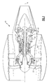
- Figure 1 illustrates a general schematic view of a gas turbine engine 10 such as a gas turbine engine for propulsion. While a two spool high bypass turbofan engine is schematically illustrated in the disclosed non-limiting embodiment, it should be understood that the disclosure is applicable to other gas turbine engine configurations, including, for example, gas turbines for power generation, turbojet engines, low bypass turbofan engines, turboshaft engines, etc.
- the engine 10 includes a core engine section that houses a low spool 14 and high spool 24.
- the low spool 14 includes a low pressure compressor 16 and a low pressure turbine 18.
- a fan 20 is coupled to the low spool 14 either directly or through a geared architecture G ( Figure 2 ).
- the high spool 24 includes a high pressure compressor 26 and high pressure turbine 28.
- a combustor 30 is arranged between the high pressure compressor 26 and high pressure turbine 28.
- the low and high spools 14, 24 rotate about an engine axis of rotation A.
- Air compressed in the compressor 16, 26 is mixed with fuel, burned in the combustor 30, and expanded in turbines 18, 28.
- the air compressed in the compressors 16, 18 and the fuel mixture expanded in the turbines 18, 28 may be referred to as a hot gas stream along a core gas path.
- a hydraulic power generation system 40 utilizes the wind-milling condition of the fan 20 to power an aircraft hydraulic system H.
- the hydraulic power generation system 40 generally includes a speed up gearbox 44, a coupling 46 and an auxiliary hydraulic pump 48.
- the hydraulic power generation system 40 utilizes the wind-milling condition of the fan 20 which is connected to the low spool 14 - typically referred to as an N1 shaft.
- the system 40 is selectively operable to maintain the desired load pressure for the aircraft hydraulic system H during the windmill condition.
- the system 40 may also be also used as emergency power to replace or assist a typical Ram Air Turbine (RAT) to reduce weight, size and space required for stowing the RAT.
- RAT Ram Air Turbine
- a windmill condition In a windmill condition, the low spool 14 rotates in response to the fan 20 being driven by airflow but the low pressure turbine section 18 does not provide rotational input.
- a windmill condition may occur during any number of situations, such as a stall or an ignition or combustion failure in the low pressure turbine section 18.
- the speed up gearbox 44 generally includes a low spool gear 50 engaged with a gear shaft 52 which, in turn, is engaged with a pinion 54.
- the gear shaft 52 and the pinion 54 may be respectively supported by bearings 56 within the speed up gearbox 44.
- a quill shaft 58 driven by the gearbox 44 connects the pinion 54 to drive the input side of the coupling 46. It should be understood that various gear arrangements may alternatively or additionally be provided.
- the coupling 46 such as a centrifugal clutch, is arranged between the speed up gearbox 44 and the auxiliary hydraulic pump 48 to selectively couple the low spool 14 thereto.
- the rotational speed of the low spool 14 under normal engine operating conditions may be approximately eight times the windmill condition speed.
- the auxiliary hydraulic pump 48 parameters can be selected to provide desired performance during the lower rotational speeds experienced during the windmill condition.
- the coupling 46 may include a set of pressure plates 60A connected to the quill shaft 58, a spring loaded piston 62, and a corresponding set of plates 60B.
- One side of the spring loaded piston 62 is pressurized via a control valve 64 such as a solenoid operated valve which may be energized by the aircraft flight control computer (FCC) 66 or other control such as a manual pilot-operated switch 68 whenever auxiliary hydraulic power is required.
- the control operates to depressurize one side of the spring loaded piston 62 to connect the quill shaft 58 to the auxiliary hydraulic pump 48 through the coupling 46.
- the coupling 46 is operable to off load the low spool 14 when the hydraulic power demand does not require utilization of the system 40 and disconnect the auxiliary hydraulic pump 48 to maximize operational life as the auxiliary hydraulic pump 48 which is typically maintained in a dormant mode for the majority of its life.
- the low spool 14 drives the auxiliary hydraulic pump 48 such as a variable displacement pressure compensated pump through the coupling 46 and the speed up gearbox 44 to operate at speeds higher than the low spool 14 to maximize the volumetric delivery of pressurized fluid.
- the auxiliary hydraulic pump 48 may be a variable displacement hydraulic pump or include a fluid control circuit 70 (illustrated schematically) which is integrated into or separate from the auxiliary hydraulic pump 48 so as to increase or decrease displacement in response to load flow demand to thereby maintain the desired load pressure for the aircraft hydraulic system H.
- the fluid control circuit 70 operates to sense the load pressure and adjusts pump displacement to maintain constant pressure regardless of the flow demand from the hydraulic system H.
- a discharge port 72 of the auxiliary hydraulic pump 48 is connected to the aircraft hydraulic system H through a check valve 74 to permit flow of pressurized fluid only from the auxiliary hydraulic pump 48 to the hydraulic system H. It should be understood that various flow controls may alternatively or additionally be provided.
- the auxiliary hydraulic pump 48 may include an off-loading valve 76 to maintain the auxiliary hydraulic pump 48 at minimum displacement during start up or when the wind-milling condition generated power is insufficient to prevent a stalling condition.
- the system 40 thereby uses the wind-milling condition of a non-operating engine to augment other hydraulic power sources (illustrated schematically at S) such as engine driven pumps or electric motor driven pumps so as to, for example: reduce the size and weight of power sources; reduce power extract from the high spool of the operating engine(s) or APU; reduce electric power consumption from operating engine(s) or APU driven generator otherwise required for electric motor driven pumps (EMPs); and reduce weight, size and space required for stowage of other emergency power systems such as a ram air turbine (RAT).
- other hydraulic power sources illustrated schematically at S
- other hydraulic power sources illustrated schematically at S
- EMPs electric motor driven pumps
- RAT ram air turbine
Landscapes
- Engineering & Computer Science (AREA)
- Chemical & Material Sciences (AREA)
- Combustion & Propulsion (AREA)
- Mechanical Engineering (AREA)
- General Engineering & Computer Science (AREA)
- Wind Motors (AREA)
- Control Of Turbines (AREA)
Abstract
Description
- The present application relates to a gas turbine engine, and more particularly to an auxiliary hydraulic power generation system therefor.
- In modem turbofan powered aircraft, an emergency power source is required for control of flight surfaces in the highly unlikely event of a total loss of the availability of the primary power sources; i.e., engine driven hydraulic pumps and/or engine driven electrical generators. For relatively small aircraft, this power is provided by the energy stored in aircraft batteries. For relatively larger aircraft, a ram air turbine (RAT) with an integral generator or auxiliary hydraulic pump is provided for deployment in an emergency situation.
- An auxiliary hydraulic power generation system according to an exemplary aspect of the present disclosure includes a first spool including a turbine. A fan is coupled to the first spool, the fan being operable to drive the first spool in a windmill condition in which the turbine fails to provide rotational drive to the fan. An auxiliary variable displacement hydraulic pump is selectively driven by the first spool in the windmill condition to augment a hydraulic power source.
- A method of hydraulic power generation according to an exemplary aspect of the present disclosure includes engaging a coupling to couple a low spool to an auxiliary variable displacement hydraulic pump to permit flow of pressurized fluid from the auxiliary hydraulic pump to an aircraft hydraulic system to augment a hydraulic power source.
- Various features will become apparent to those skilled in the art from the following detailed description of the disclosed non-limiting embodiment. The drawings that accompany the detailed description can be briefly described as follows:
-
Figure 1 is a schematic sectional view through a gas turbine engine along the engine longitudinal axis; and -
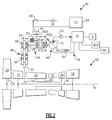
Figure 2 is a schematic view of a hydraulic power generation system. -
Figure 1 illustrates a general schematic view of agas turbine engine 10 such as a gas turbine engine for propulsion. While a two spool high bypass turbofan engine is schematically illustrated in the disclosed non-limiting embodiment, it should be understood that the disclosure is applicable to other gas turbine engine configurations, including, for example, gas turbines for power generation, turbojet engines, low bypass turbofan engines, turboshaft engines, etc. - The
engine 10 includes a core engine section that houses alow spool 14 andhigh spool 24. Thelow spool 14 includes alow pressure compressor 16 and alow pressure turbine 18. Afan 20 is coupled to thelow spool 14 either directly or through a geared architecture G (Figure 2 ). Thehigh spool 24 includes ahigh pressure compressor 26 andhigh pressure turbine 28. Acombustor 30 is arranged between thehigh pressure compressor 26 andhigh pressure turbine 28. The low andhigh spools - Air compressed in the
compressor combustor 30, and expanded inturbines compressors turbines turbines compressors fan 20 either directly or through a geared architecture. - With reference to
Figure 2 , a hydraulicpower generation system 40 utilizes the wind-milling condition of thefan 20 to power an aircraft hydraulic system H. The hydraulicpower generation system 40 generally includes a speed upgearbox 44, acoupling 46 and an auxiliaryhydraulic pump 48. The hydraulicpower generation system 40 utilizes the wind-milling condition of thefan 20 which is connected to the low spool 14 - typically referred to as an N1 shaft. Thesystem 40 is selectively operable to maintain the desired load pressure for the aircraft hydraulic system H during the windmill condition. Thesystem 40 may also be also used as emergency power to replace or assist a typical Ram Air Turbine (RAT) to reduce weight, size and space required for stowing the RAT. - In a windmill condition, the
low spool 14 rotates in response to thefan 20 being driven by airflow but the lowpressure turbine section 18 does not provide rotational input. A windmill condition may occur during any number of situations, such as a stall or an ignition or combustion failure in the lowpressure turbine section 18. - The speed up
gearbox 44 generally includes alow spool gear 50 engaged with agear shaft 52 which, in turn, is engaged with apinion 54. Thegear shaft 52 and thepinion 54 may be respectively supported bybearings 56 within the speed upgearbox 44. Aquill shaft 58 driven by thegearbox 44 connects thepinion 54 to drive the input side of thecoupling 46. It should be understood that various gear arrangements may alternatively or additionally be provided. - The
coupling 46, such as a centrifugal clutch, is arranged between the speed upgearbox 44 and the auxiliaryhydraulic pump 48 to selectively couple thelow spool 14 thereto. In one example, the rotational speed of thelow spool 14 under normal engine operating conditions may be approximately eight times the windmill condition speed. As a result, it may be desirable for thecoupling 46 to decouple thelow spool 14 from the auxiliaryhydraulic pump 48 above a predetermined rotational speed. As a result, the auxiliaryhydraulic pump 48 parameters can be selected to provide desired performance during the lower rotational speeds experienced during the windmill condition. - The
coupling 46 may include a set ofpressure plates 60A connected to thequill shaft 58, a spring loadedpiston 62, and a corresponding set ofplates 60B. One side of the spring loadedpiston 62 is pressurized via acontrol valve 64 such as a solenoid operated valve which may be energized by the aircraft flight control computer (FCC) 66 or other control such as a manual pilot-operatedswitch 68 whenever auxiliary hydraulic power is required. The control operates to depressurize one side of the spring loadedpiston 62 to connect thequill shaft 58 to the auxiliaryhydraulic pump 48 through thecoupling 46. - The
coupling 46 is operable to off load thelow spool 14 when the hydraulic power demand does not require utilization of thesystem 40 and disconnect the auxiliaryhydraulic pump 48 to maximize operational life as the auxiliaryhydraulic pump 48 which is typically maintained in a dormant mode for the majority of its life. - The
low spool 14 drives the auxiliaryhydraulic pump 48 such as a variable displacement pressure compensated pump through thecoupling 46 and the speed upgearbox 44 to operate at speeds higher than thelow spool 14 to maximize the volumetric delivery of pressurized fluid. The auxiliaryhydraulic pump 48 may be a variable displacement hydraulic pump or include a fluid control circuit 70 (illustrated schematically) which is integrated into or separate from the auxiliaryhydraulic pump 48 so as to increase or decrease displacement in response to load flow demand to thereby maintain the desired load pressure for the aircraft hydraulic system H. Thefluid control circuit 70 operates to sense the load pressure and adjusts pump displacement to maintain constant pressure regardless of the flow demand from the hydraulic system H. - In one non-limiting embodiment, a
discharge port 72 of the auxiliaryhydraulic pump 48 is connected to the aircraft hydraulic system H through acheck valve 74 to permit flow of pressurized fluid only from the auxiliaryhydraulic pump 48 to the hydraulic system H. It should be understood that various flow controls may alternatively or additionally be provided. - In another non-limiting embodiment, the auxiliary
hydraulic pump 48 may include an off-loading valve 76 to maintain the auxiliaryhydraulic pump 48 at minimum displacement during start up or when the wind-milling condition generated power is insufficient to prevent a stalling condition. - The
system 40 thereby uses the wind-milling condition of a non-operating engine to augment other hydraulic power sources (illustrated schematically at S) such as engine driven pumps or electric motor driven pumps so as to, for example: reduce the size and weight of power sources; reduce power extract from the high spool of the operating engine(s) or APU; reduce electric power consumption from operating engine(s) or APU driven generator otherwise required for electric motor driven pumps (EMPs); and reduce weight, size and space required for stowage of other emergency power systems such as a ram air turbine (RAT). - It should be understood that relative positional terms such as "forward," "aft," "upper," "lower," "above," "below," and the like are with reference to the normal operational attitude of the vehicle and should not be considered otherwise limiting.
- The foregoing description is exemplary rather than defined by the limitations within. Many modifications and variations of the present invention are possible in light of the above teachings. The disclosed embodiments of this invention have been disclosed, however, one of ordinary skill in the art would recognize that certain modifications would come within the scope of this invention. It is, therefore, to be understood that within the scope of the appended claims, the invention may be practiced otherwise than as specifically described. For that reason the following claims should be studied to determine the true scope and content of this invention.
Claims (15)
- A hydraulic power generation (40) system comprising:a first spool (14) including a turbine (18);a fan (20) coupled to said first spool, said fan being operable to drive said first spool in a windmill condition in which said turbine fails to provide rotational drive to said fan; andan auxiliary variable displacement hydraulic pump (48) for being selectively driven by said first spool in said windmill condition to augment a hydraulic power source.
- The system as recited in claim 1, further comprising a speed up gearbox (44) between said first spool (14) and said auxiliary variable displacement hydraulic pump (48).
- The system as recited in claim 2, further comprising a coupling (46) between said speed up gearbox (44) and said auxiliary variable displacement hydraulic pump for selectively driving the auxiliary variable displacement hydraulic pump with said first spool in the windmill condition.
- The system as recited in claim 1, 2 or 3, wherein said first spool (14) is a low pressure spool.
- The system as recited in claim 3, wherein said coupling (46) includes a clutch.
- The system as recited in any preceding claim, wherein a discharge port (72) of said auxiliary variable displacement hydraulic pump (48) is connected to an aircraft hydraulic system (H) through a check valve (74) to permit flow of pressurized fluid only from said auxiliary variable displacement hydraulic pump to said aircraft hydraulic system.
- The system as recited in any preceding claim, further comprising an off-loading valve (76) to maintain said auxiliary variable displacement hydraulic pump (48) at a minimum displacement during start up.
- The system as recited in any one of claims 1 to 6, further comprising an off-loading valve (76) to maintain said auxiliary variable displacement hydraulic pump (48) at a minimum displacement when windmill generated power is insufficient to prevent a stalling condition.
- The system as recited in any preceding claim, wherein said hydraulic power source is an engine driven pump.
- The system as recited in any one of claims 1 to 8, wherein said hydraulic power source is an electric motor driven pump.
- A method of auxiliary hydraulic power generation comprising:engaging a coupling (46) to couple a low spool (14) of a turbine engine to an auxiliary variable displacement hydraulic pump (48) to provide a flow of pressurized fluid between the auxiliary variable displacement hydraulic pump to an aircraft hydraulic system (H).
- The method as recited in claim 11, wherein the coupling (46) couples the low spool (14) to the auxiliary variable displacement hydraulic pump (48) in response to the low spool entering a windmill condition.
- The method as recited in claim 11, wherein the coupling (46) couples the low spool (14) to the auxiliary variable displacement hydraulic pump (48) in response to a manually activated condition.
- The method as recited in claim 11, 12 or 13, further comprising maintaining the auxiliary variable displacement hydraulic pump (48) at a minimum displacement.
- The method as recited in claim 11, 12 or 13, further comprising maintaining the auxiliary variable displacement hydraulic pump (48) at a minimum displacement when windmill generated power is insufficient to prevent a stalling condition to augment a hydraulic power source.
Applications Claiming Priority (1)
| Application Number | Priority Date | Filing Date | Title |
|---|---|---|---|
| US12/834,936 US20120011839A1 (en) | 2010-07-13 | 2010-07-13 | Auxiliary hydraulic power generation system |
Publications (3)
| Publication Number | Publication Date |
|---|---|
| EP2407660A2 true EP2407660A2 (en) | 2012-01-18 |
| EP2407660A3 EP2407660A3 (en) | 2015-03-04 |
| EP2407660B1 EP2407660B1 (en) | 2019-04-17 |
Family
ID=44510048
Family Applications (1)
| Application Number | Title | Priority Date | Filing Date |
|---|---|---|---|
| EP11172289.8A Active EP2407660B1 (en) | 2010-07-13 | 2011-06-30 | Auxiliary hydraulic power generation system |
Country Status (3)
| Country | Link |
|---|---|
| US (1) | US20120011839A1 (en) |
| EP (1) | EP2407660B1 (en) |
| CN (1) | CN102383943B (en) |
Families Citing this family (9)
| Publication number | Priority date | Publication date | Assignee | Title |
|---|---|---|---|---|
| WO2013165771A1 (en) * | 2012-04-30 | 2013-11-07 | United Technologies Corporation | Geared turbofan with distributed accessory gearboxes |
| US8814075B1 (en) * | 2013-02-11 | 2014-08-26 | T&CO Energy Services, Inc. | Modular system and method for deployment and retrieval of large diameter hoses |
| US20150158597A1 (en) * | 2013-12-10 | 2015-06-11 | United Technologies Corporation | Emergency power generation via limited variable pitch fan blade |
| US9409653B2 (en) * | 2014-09-17 | 2016-08-09 | The Boeing Company | Auxilliary power and thrust unit drive system |
| CN104632741B (en) * | 2014-12-10 | 2017-01-11 | 中国航空工业集团公司金城南京机电液压工程研究中心 | Warm flow valve for hydraulic type ram air turbine |
| US10273883B2 (en) * | 2016-02-26 | 2019-04-30 | The Boeing Company | Engine accessory drives systems and methods |
| CN107128495A (en) * | 2017-04-19 | 2017-09-05 | 中国航空工业集团公司金城南京机电液压工程研究中心 | A kind of Ram Air Turbine Systems |
| CN111577567B (en) * | 2020-06-09 | 2024-04-30 | 中国石油天然气集团有限公司 | Gas-liquid coupling stamping device for gas drilling |
| US12378916B2 (en) | 2022-11-18 | 2025-08-05 | Pratt & Whitney Canada Corp. | Engine power extraction system and method for using same |
Family Cites Families (12)
| Publication number | Priority date | Publication date | Assignee | Title |
|---|---|---|---|---|
| GB759548A (en) * | 1954-04-20 | 1956-10-17 | Hobson Ltd H M | Improvements in hydraulic servo systems |
| US4912921A (en) * | 1988-03-14 | 1990-04-03 | Sundstrand Corporation | Low speed spool emergency power extraction system |
| US5687561A (en) * | 1991-09-17 | 1997-11-18 | Rolls-Royce Plc | Ducted fan gas turbine engine accessory drive |
| GB9313905D0 (en) * | 1993-07-06 | 1993-08-25 | Rolls Royce Plc | Shaft power transfer in gas turbine engines |
| US5845483A (en) * | 1996-04-10 | 1998-12-08 | General Electric Company | Windmill engine starting system with fluid driven motor and pump |
| JP3774014B2 (en) * | 1997-01-27 | 2006-05-10 | コベルコ建機株式会社 | Control device for hydraulic work machine |
| US6209825B1 (en) * | 1998-02-27 | 2001-04-03 | Lockheed Martin Corporation | Low power loss electro hydraulic actuator |
| WO2000059780A2 (en) * | 1999-04-01 | 2000-10-12 | Hamilton Sundstrand Corporation | Flywheel peaking unit for an aircraft hydraulic system |
| US6704625B2 (en) * | 2001-02-16 | 2004-03-09 | Hamilton Sunstrand Corporation | Aircraft architecture with a reduced bleed aircraft secondary power system |
| US20060137355A1 (en) * | 2004-12-27 | 2006-06-29 | Pratt & Whitney Canada Corp. | Fan driven emergency generator |
| DE102006003138A1 (en) * | 2006-01-24 | 2007-08-02 | Airbus Deutschland Gmbh | Emergency supply device for use in aeroplane, has back pressure turbine that is surrounded concentrically by jacket which forms flow channel and energy transducer is coupled directly to back pressure turbine |
| CN101655116B (en) * | 2009-09-17 | 2011-12-14 | 成都成设航空科技有限公司 | Hydraulic power source system |
-
2010
- 2010-07-13 US US12/834,936 patent/US20120011839A1/en not_active Abandoned
-
2011
- 2011-06-30 EP EP11172289.8A patent/EP2407660B1/en active Active
- 2011-07-13 CN CN201110195776.XA patent/CN102383943B/en active Active
Non-Patent Citations (1)
| Title |
|---|
| None |
Also Published As
| Publication number | Publication date |
|---|---|
| EP2407660B1 (en) | 2019-04-17 |
| US20120011839A1 (en) | 2012-01-19 |
| CN102383943B (en) | 2015-06-24 |
| EP2407660A3 (en) | 2015-03-04 |
| CN102383943A (en) | 2012-03-21 |
Similar Documents
| Publication | Publication Date | Title |
|---|---|---|
| EP2407660B1 (en) | Auxiliary hydraulic power generation system | |
| US11427340B2 (en) | Propulsion system for an aircraft | |
| EP3002435B1 (en) | Accessory drive system for a gas turbine engine | |
| EP2133537B1 (en) | Bi-modal air turbine starter assembly | |
| EP1726879B1 (en) | Reduced-weight fuel system for a gas turbine engine, gas turbine engine including such a system, and method of providing fuel to such a gas turbine engine | |
| US9151180B2 (en) | Lubrication driven gas turbine engine actuation system | |
| US7118336B2 (en) | Pressurized oil supply for propeller engine system | |
| EP2065585B1 (en) | Gas turbine engine with pylon mounted accessory drive | |
| JP6637898B2 (en) | Propulsion systems and helicopters | |
| CN112664320A (en) | Gas turbine engine supercharger configuration and method of operation | |
| EP2602458A2 (en) | Multiple turboshaft engine control method and system for helicopters | |
| US20060137355A1 (en) | Fan driven emergency generator | |
| US8966876B2 (en) | Controllable speed windmill operation of a gas turbine engine through low spool power extraction | |
| EP4624736A1 (en) | Electric compressor stage for a gas turbine engine |
Legal Events
| Date | Code | Title | Description |
|---|---|---|---|
| AK | Designated contracting states |
Kind code of ref document: A2 Designated state(s): AL AT BE BG CH CY CZ DE DK EE ES FI FR GB GR HR HU IE IS IT LI LT LU LV MC MK MT NL NO PL PT RO RS SE SI SK SM TR |
|
| AX | Request for extension of the european patent |
Extension state: BA ME |
|
| PUAI | Public reference made under article 153(3) epc to a published international application that has entered the european phase |
Free format text: ORIGINAL CODE: 0009012 |
|
| PUAL | Search report despatched |
Free format text: ORIGINAL CODE: 0009013 |
|
| AK | Designated contracting states |
Kind code of ref document: A3 Designated state(s): AL AT BE BG CH CY CZ DE DK EE ES FI FR GB GR HR HU IE IS IT LI LT LU LV MC MK MT NL NO PL PT RO RS SE SI SK SM TR |
|
| AX | Request for extension of the european patent |
Extension state: BA ME |
|
| RIC1 | Information provided on ipc code assigned before grant |
Ipc: F02C 7/32 20060101ALI20150129BHEP Ipc: F01D 17/26 20060101ALI20150129BHEP Ipc: F02K 3/06 20060101AFI20150129BHEP |
|
| 17P | Request for examination filed |
Effective date: 20150811 |
|
| RBV | Designated contracting states (corrected) |
Designated state(s): AL AT BE BG CH CY CZ DE DK EE ES FI FR GB GR HR HU IE IS IT LI LT LU LV MC MK MT NL NO PL PT RO RS SE SI SK SM TR |
|
| STAA | Information on the status of an ep patent application or granted ep patent |
Free format text: STATUS: EXAMINATION IS IN PROGRESS |
|
| 17Q | First examination report despatched |
Effective date: 20171129 |
|
| GRAP | Despatch of communication of intention to grant a patent |
Free format text: ORIGINAL CODE: EPIDOSNIGR1 |
|
| STAA | Information on the status of an ep patent application or granted ep patent |
Free format text: STATUS: GRANT OF PATENT IS INTENDED |
|
| INTG | Intention to grant announced |
Effective date: 20181029 |
|
| GRAS | Grant fee paid |
Free format text: ORIGINAL CODE: EPIDOSNIGR3 |
|
| GRAA | (expected) grant |
Free format text: ORIGINAL CODE: 0009210 |
|
| STAA | Information on the status of an ep patent application or granted ep patent |
Free format text: STATUS: THE PATENT HAS BEEN GRANTED |
|
| AK | Designated contracting states |
Kind code of ref document: B1 Designated state(s): AL AT BE BG CH CY CZ DE DK EE ES FI FR GB GR HR HU IE IS IT LI LT LU LV MC MK MT NL NO PL PT RO RS SE SI SK SM TR |
|
| REG | Reference to a national code |
Ref country code: GB Ref legal event code: FG4D |
|
| REG | Reference to a national code |
Ref country code: CH Ref legal event code: EP |
|
| REG | Reference to a national code |
Ref country code: DE Ref legal event code: R096 Ref document number: 602011058091 Country of ref document: DE |
|
| REG | Reference to a national code |
Ref country code: AT Ref legal event code: REF Ref document number: 1121819 Country of ref document: AT Kind code of ref document: T Effective date: 20190515 Ref country code: IE Ref legal event code: FG4D |
|
| REG | Reference to a national code |
Ref country code: NL Ref legal event code: MP Effective date: 20190417 |
|
| REG | Reference to a national code |
Ref country code: LT Ref legal event code: MG4D |
|
| PG25 | Lapsed in a contracting state [announced via postgrant information from national office to epo] |
Ref country code: NL Free format text: LAPSE BECAUSE OF FAILURE TO SUBMIT A TRANSLATION OF THE DESCRIPTION OR TO PAY THE FEE WITHIN THE PRESCRIBED TIME-LIMIT Effective date: 20190417 |
|
| PG25 | Lapsed in a contracting state [announced via postgrant information from national office to epo] |
Ref country code: AL Free format text: LAPSE BECAUSE OF FAILURE TO SUBMIT A TRANSLATION OF THE DESCRIPTION OR TO PAY THE FEE WITHIN THE PRESCRIBED TIME-LIMIT Effective date: 20190417 Ref country code: ES Free format text: LAPSE BECAUSE OF FAILURE TO SUBMIT A TRANSLATION OF THE DESCRIPTION OR TO PAY THE FEE WITHIN THE PRESCRIBED TIME-LIMIT Effective date: 20190417 Ref country code: FI Free format text: LAPSE BECAUSE OF FAILURE TO SUBMIT A TRANSLATION OF THE DESCRIPTION OR TO PAY THE FEE WITHIN THE PRESCRIBED TIME-LIMIT Effective date: 20190417 Ref country code: LT Free format text: LAPSE BECAUSE OF FAILURE TO SUBMIT A TRANSLATION OF THE DESCRIPTION OR TO PAY THE FEE WITHIN THE PRESCRIBED TIME-LIMIT Effective date: 20190417 Ref country code: SE Free format text: LAPSE BECAUSE OF FAILURE TO SUBMIT A TRANSLATION OF THE DESCRIPTION OR TO PAY THE FEE WITHIN THE PRESCRIBED TIME-LIMIT Effective date: 20190417 Ref country code: PT Free format text: LAPSE BECAUSE OF FAILURE TO SUBMIT A TRANSLATION OF THE DESCRIPTION OR TO PAY THE FEE WITHIN THE PRESCRIBED TIME-LIMIT Effective date: 20190817 Ref country code: NO Free format text: LAPSE BECAUSE OF FAILURE TO SUBMIT A TRANSLATION OF THE DESCRIPTION OR TO PAY THE FEE WITHIN THE PRESCRIBED TIME-LIMIT Effective date: 20190717 Ref country code: HR Free format text: LAPSE BECAUSE OF FAILURE TO SUBMIT A TRANSLATION OF THE DESCRIPTION OR TO PAY THE FEE WITHIN THE PRESCRIBED TIME-LIMIT Effective date: 20190417 |
|
| PG25 | Lapsed in a contracting state [announced via postgrant information from national office to epo] |
Ref country code: LV Free format text: LAPSE BECAUSE OF FAILURE TO SUBMIT A TRANSLATION OF THE DESCRIPTION OR TO PAY THE FEE WITHIN THE PRESCRIBED TIME-LIMIT Effective date: 20190417 Ref country code: GR Free format text: LAPSE BECAUSE OF FAILURE TO SUBMIT A TRANSLATION OF THE DESCRIPTION OR TO PAY THE FEE WITHIN THE PRESCRIBED TIME-LIMIT Effective date: 20190718 Ref country code: PL Free format text: LAPSE BECAUSE OF FAILURE TO SUBMIT A TRANSLATION OF THE DESCRIPTION OR TO PAY THE FEE WITHIN THE PRESCRIBED TIME-LIMIT Effective date: 20190417 Ref country code: RS Free format text: LAPSE BECAUSE OF FAILURE TO SUBMIT A TRANSLATION OF THE DESCRIPTION OR TO PAY THE FEE WITHIN THE PRESCRIBED TIME-LIMIT Effective date: 20190417 Ref country code: BG Free format text: LAPSE BECAUSE OF FAILURE TO SUBMIT A TRANSLATION OF THE DESCRIPTION OR TO PAY THE FEE WITHIN THE PRESCRIBED TIME-LIMIT Effective date: 20190717 |
|
| REG | Reference to a national code |
Ref country code: AT Ref legal event code: MK05 Ref document number: 1121819 Country of ref document: AT Kind code of ref document: T Effective date: 20190417 |
|
| PG25 | Lapsed in a contracting state [announced via postgrant information from national office to epo] |
Ref country code: IS Free format text: LAPSE BECAUSE OF FAILURE TO SUBMIT A TRANSLATION OF THE DESCRIPTION OR TO PAY THE FEE WITHIN THE PRESCRIBED TIME-LIMIT Effective date: 20190817 |
|
| REG | Reference to a national code |
Ref country code: DE Ref legal event code: R097 Ref document number: 602011058091 Country of ref document: DE |
|
| PG25 | Lapsed in a contracting state [announced via postgrant information from national office to epo] |
Ref country code: MC Free format text: LAPSE BECAUSE OF FAILURE TO SUBMIT A TRANSLATION OF THE DESCRIPTION OR TO PAY THE FEE WITHIN THE PRESCRIBED TIME-LIMIT Effective date: 20190417 Ref country code: AT Free format text: LAPSE BECAUSE OF FAILURE TO SUBMIT A TRANSLATION OF THE DESCRIPTION OR TO PAY THE FEE WITHIN THE PRESCRIBED TIME-LIMIT Effective date: 20190417 Ref country code: CZ Free format text: LAPSE BECAUSE OF FAILURE TO SUBMIT A TRANSLATION OF THE DESCRIPTION OR TO PAY THE FEE WITHIN THE PRESCRIBED TIME-LIMIT Effective date: 20190417 Ref country code: RO Free format text: LAPSE BECAUSE OF FAILURE TO SUBMIT A TRANSLATION OF THE DESCRIPTION OR TO PAY THE FEE WITHIN THE PRESCRIBED TIME-LIMIT Effective date: 20190417 Ref country code: SK Free format text: LAPSE BECAUSE OF FAILURE TO SUBMIT A TRANSLATION OF THE DESCRIPTION OR TO PAY THE FEE WITHIN THE PRESCRIBED TIME-LIMIT Effective date: 20190417 Ref country code: EE Free format text: LAPSE BECAUSE OF FAILURE TO SUBMIT A TRANSLATION OF THE DESCRIPTION OR TO PAY THE FEE WITHIN THE PRESCRIBED TIME-LIMIT Effective date: 20190417 Ref country code: DK Free format text: LAPSE BECAUSE OF FAILURE TO SUBMIT A TRANSLATION OF THE DESCRIPTION OR TO PAY THE FEE WITHIN THE PRESCRIBED TIME-LIMIT Effective date: 20190417 |
|
| REG | Reference to a national code |
Ref country code: CH Ref legal event code: PL |
|
| PLBE | No opposition filed within time limit |
Free format text: ORIGINAL CODE: 0009261 |
|
| STAA | Information on the status of an ep patent application or granted ep patent |
Free format text: STATUS: NO OPPOSITION FILED WITHIN TIME LIMIT |
|
| PG25 | Lapsed in a contracting state [announced via postgrant information from national office to epo] |
Ref country code: IT Free format text: LAPSE BECAUSE OF FAILURE TO SUBMIT A TRANSLATION OF THE DESCRIPTION OR TO PAY THE FEE WITHIN THE PRESCRIBED TIME-LIMIT Effective date: 20190417 Ref country code: SM Free format text: LAPSE BECAUSE OF FAILURE TO SUBMIT A TRANSLATION OF THE DESCRIPTION OR TO PAY THE FEE WITHIN THE PRESCRIBED TIME-LIMIT Effective date: 20190417 |
|
| 26N | No opposition filed |
Effective date: 20200120 |
|
| REG | Reference to a national code |
Ref country code: BE Ref legal event code: MM Effective date: 20190630 |
|
| PG25 | Lapsed in a contracting state [announced via postgrant information from national office to epo] |
Ref country code: TR Free format text: LAPSE BECAUSE OF FAILURE TO SUBMIT A TRANSLATION OF THE DESCRIPTION OR TO PAY THE FEE WITHIN THE PRESCRIBED TIME-LIMIT Effective date: 20190417 |
|
| PG25 | Lapsed in a contracting state [announced via postgrant information from national office to epo] |
Ref country code: IE Free format text: LAPSE BECAUSE OF NON-PAYMENT OF DUE FEES Effective date: 20190630 |
|
| PG25 | Lapsed in a contracting state [announced via postgrant information from national office to epo] |
Ref country code: SI Free format text: LAPSE BECAUSE OF FAILURE TO SUBMIT A TRANSLATION OF THE DESCRIPTION OR TO PAY THE FEE WITHIN THE PRESCRIBED TIME-LIMIT Effective date: 20190417 Ref country code: BE Free format text: LAPSE BECAUSE OF NON-PAYMENT OF DUE FEES Effective date: 20190630 Ref country code: LU Free format text: LAPSE BECAUSE OF NON-PAYMENT OF DUE FEES Effective date: 20190630 Ref country code: LI Free format text: LAPSE BECAUSE OF NON-PAYMENT OF DUE FEES Effective date: 20190630 Ref country code: CH Free format text: LAPSE BECAUSE OF NON-PAYMENT OF DUE FEES Effective date: 20190630 |
|
| PG25 | Lapsed in a contracting state [announced via postgrant information from national office to epo] |
Ref country code: CY Free format text: LAPSE BECAUSE OF FAILURE TO SUBMIT A TRANSLATION OF THE DESCRIPTION OR TO PAY THE FEE WITHIN THE PRESCRIBED TIME-LIMIT Effective date: 20190417 |
|
| PG25 | Lapsed in a contracting state [announced via postgrant information from national office to epo] |
Ref country code: HU Free format text: LAPSE BECAUSE OF FAILURE TO SUBMIT A TRANSLATION OF THE DESCRIPTION OR TO PAY THE FEE WITHIN THE PRESCRIBED TIME-LIMIT; INVALID AB INITIO Effective date: 20110630 Ref country code: MT Free format text: LAPSE BECAUSE OF FAILURE TO SUBMIT A TRANSLATION OF THE DESCRIPTION OR TO PAY THE FEE WITHIN THE PRESCRIBED TIME-LIMIT Effective date: 20190417 |
|
| PG25 | Lapsed in a contracting state [announced via postgrant information from national office to epo] |
Ref country code: MK Free format text: LAPSE BECAUSE OF FAILURE TO SUBMIT A TRANSLATION OF THE DESCRIPTION OR TO PAY THE FEE WITHIN THE PRESCRIBED TIME-LIMIT Effective date: 20190417 |
|
| P01 | Opt-out of the competence of the unified patent court (upc) registered |
Effective date: 20230522 |
|
| PGFP | Annual fee paid to national office [announced via postgrant information from national office to epo] |
Ref country code: DE Payment date: 20250520 Year of fee payment: 15 |
|
| PGFP | Annual fee paid to national office [announced via postgrant information from national office to epo] |
Ref country code: GB Payment date: 20250520 Year of fee payment: 15 |
|
| PGFP | Annual fee paid to national office [announced via postgrant information from national office to epo] |
Ref country code: FR Payment date: 20250520 Year of fee payment: 15 |