EP2407642A2 - Systems, methods, and apparatus for determining steady state conditions in a gas turbine - Google Patents
Systems, methods, and apparatus for determining steady state conditions in a gas turbine Download PDFInfo
- Publication number
- EP2407642A2 EP2407642A2 EP20110172741 EP11172741A EP2407642A2 EP 2407642 A2 EP2407642 A2 EP 2407642A2 EP 20110172741 EP20110172741 EP 20110172741 EP 11172741 A EP11172741 A EP 11172741A EP 2407642 A2 EP2407642 A2 EP 2407642A2
- Authority
- EP
- European Patent Office
- Prior art keywords
- vgv
- fsr
- filtered
- stability
- change
- Prior art date
- Legal status (The legal status is an assumption and is not a legal conclusion. Google has not performed a legal analysis and makes no representation as to the accuracy of the status listed.)
- Granted
Links
Images


Classifications
-
- F—MECHANICAL ENGINEERING; LIGHTING; HEATING; WEAPONS; BLASTING
- F02—COMBUSTION ENGINES; HOT-GAS OR COMBUSTION-PRODUCT ENGINE PLANTS
- F02C—GAS-TURBINE PLANTS; AIR INTAKES FOR JET-PROPULSION PLANTS; CONTROLLING FUEL SUPPLY IN AIR-BREATHING JET-PROPULSION PLANTS
- F02C9/00—Controlling gas-turbine plants; Controlling fuel supply in air- breathing jet-propulsion plants
- F02C9/48—Control of fuel supply conjointly with another control of the plant
- F02C9/50—Control of fuel supply conjointly with another control of the plant with control of working fluid flow
- F02C9/54—Control of fuel supply conjointly with another control of the plant with control of working fluid flow by throttling the working fluid, by adjusting vanes
-
- F—MECHANICAL ENGINEERING; LIGHTING; HEATING; WEAPONS; BLASTING
- F05—INDEXING SCHEMES RELATING TO ENGINES OR PUMPS IN VARIOUS SUBCLASSES OF CLASSES F01-F04
- F05D—INDEXING SCHEME FOR ASPECTS RELATING TO NON-POSITIVE-DISPLACEMENT MACHINES OR ENGINES, GAS-TURBINES OR JET-PROPULSION PLANTS
- F05D2200/00—Mathematical features
- F05D2200/20—Special functions
-
- F—MECHANICAL ENGINEERING; LIGHTING; HEATING; WEAPONS; BLASTING
- F05—INDEXING SCHEMES RELATING TO ENGINES OR PUMPS IN VARIOUS SUBCLASSES OF CLASSES F01-F04
- F05D—INDEXING SCHEME FOR ASPECTS RELATING TO NON-POSITIVE-DISPLACEMENT MACHINES OR ENGINES, GAS-TURBINES OR JET-PROPULSION PLANTS
- F05D2270/00—Control
- F05D2270/01—Purpose of the control system
- F05D2270/02—Purpose of the control system to control rotational speed (n)
- F05D2270/024—Purpose of the control system to control rotational speed (n) to keep rotational speed constant
-
- F—MECHANICAL ENGINEERING; LIGHTING; HEATING; WEAPONS; BLASTING
- F05—INDEXING SCHEMES RELATING TO ENGINES OR PUMPS IN VARIOUS SUBCLASSES OF CLASSES F01-F04
- F05D—INDEXING SCHEME FOR ASPECTS RELATING TO NON-POSITIVE-DISPLACEMENT MACHINES OR ENGINES, GAS-TURBINES OR JET-PROPULSION PLANTS
- F05D2270/00—Control
- F05D2270/30—Control parameters, e.g. input parameters
- F05D2270/309—Rate of change of parameters
-
- F—MECHANICAL ENGINEERING; LIGHTING; HEATING; WEAPONS; BLASTING
- F05—INDEXING SCHEMES RELATING TO ENGINES OR PUMPS IN VARIOUS SUBCLASSES OF CLASSES F01-F04
- F05D—INDEXING SCHEME FOR ASPECTS RELATING TO NON-POSITIVE-DISPLACEMENT MACHINES OR ENGINES, GAS-TURBINES OR JET-PROPULSION PLANTS
- F05D2270/00—Control
- F05D2270/40—Type of control system
- F05D2270/44—Type of control system active, predictive, or anticipative
Definitions
- This invention generally relates to gas turbines, and in particular, to determining steady state conditions associated with the turbine.
- Gas turbines are typically large, complex, and expensive machines that operate under challenging environmental conditions. Building, maintaining, and operating these machines often requires a significant capital investment, and therefore, steps are often taken to ramp-up and ramp-down the turbines under careful control, in order to protect the capital investment, and operate the turbine within safe limits.
- Certain embodiments of the invention may include systems, methods, and apparatus for determining steady state conditions associated with the turbine.
- a method for determining stability in a gas turbine can include receiving a guide vane (VGV) command and a fuel stroke reference (FSR) command associated with a gas turbine control system, determining a filtered VGV change based at least in part on the received VGV command, determining a filtered FSR change based at least in part on the received FSR command, and outputting a unit stability signal after a pickup delay time when the filtered VGV change is less than a predetermined VGV stability threshold and the filtered FSR change is less than a predetermined FSR stability threshold.
- VGV guide vane
- FSR fuel stroke reference
- a system for determining stability.
- the system can include a gas turbine, at least one memory for storing data and computer-executable instructions, and at least one processor configured to access the at least one memory.
- the at least one processor is further configured to execute the computer-executable instructions for receiving a guide vane (VGV) command and a fuel stroke reference (FSR) command associated with the gas turbine, determining a filtered VGV change based at least in part on the received VGV command, determining a filtered FSR change based at least in part on the received FSR command, and outputting a unit stability signal after a pickup delay time when the filtered VGV change is less than a predetermined VGV stability threshold and the filtered FSR change is less than a predetermined FSR stability threshold.
- VGV guide vane
- FSR fuel stroke reference
- an apparatus for determining stability in a gas turbine.
- the apparatus can include at least one memory for storing data and computer-executable instructions.
- the apparatus can also include at least one processor configured to access the at least one memory and further configured to execute the computer-executable instructions for receiving a guide vane (VGV) command and a fuel stroke reference (FSR) command associated with a gas turbine, determining a filtered VGV change based at least in part on the received VGV command, determining a filtered FSR change based at least in part on the received FSR command, and outputting a unit stability signal after a pickup delay time when the filtered VGV change is less than a predetermined VGV stability threshold and the filtered FSR change is less than a predetermined FSR stability threshold.
- VGV guide vane
- FSR fuel stroke reference
- monitoring control commands instead of feedback parameters, may provide certain advantages for determining if a turbine has reached stability or steady state.
- Feedback parameters such as exhaust temperature, power output, airflow, or fuel flow, for example, could be measured to provide feedback for determining the stability of the turbine.
- exhaust temperature may be one variable to consider as a variable for determining turbine stability.
- the turbine may actually be operating under stable condition minutes before such stability is reflected in the exhaust temperature. Therefore, according to example embodiments of the invention, commands associated with the fuel and guide vanes may be utilized a more direct measure of the turbine stability.
- turbine protection algorithms may need to know if the unit is at steady state before enabling their protection. Some of these algorithms may need be disabled before disturbances appear on output parameters such as pyrometer temperatures.
- a stability algorithm is provided. According to example embodiments, the algorithm may be robust and accurate enough to prevent false protective actions, and it may be fast enough to ensure stability is confirmed or disabled before certain output parameters are significantly affected.
- FIG. 1 is a block diagram illustrating an example turbine stability detection system 100, according to example embodiments of the invention.
- the system 100 may include one or more sensor(s) 102 for measuring parameters, and/or events associated with the turbine.
- the sensors 102 may include linear variable differential transformers (LVDTs), pyrometer sensors, emissivity sensors, temperature sensors, gas sensors, pressure sensors, cameras, acoustical sensors, etc.
- the system 100 may also include one or more data capture modules 104 that may be configured to receive and condition the parameter information measured by the sensors 102.
- the data capture modules 104 may include analog to digital converters, level shifting, filtering, calibration, power supplies, etc., for proper communication with the sensors 102 and/or for conditioning the signals received from the sensors 102.
- the data capture module(s) 104 may communicate with a signal-processing module 106.
- the signal-processing module 106 may further process the information received from the sensor(s) 102 via the data capture module(s) 104. For example, the signal-processing module 106 may average or filter the incoming data. In certain embodiments, the signal-processing module 106 may scale and/or format the data.
- a stability detection 112 module may monitor turbine commands 110 to enable a protection module 108 only after certain criteria are met. For example, the stability detection module 112 may monitor turbine commands 110 to determine if the turbine has reached steady state operation, and/or if other criteria are met.
- the stability detection module 112 may inhibit the protection module 108 and keep it from initiating a shutdown of the system via the turbine controls 114 until after the stability criteria are met. For example, shutdown may be initiated upon detection of an event and after turbine has initialized or stabilized.
- turbine commands 110 such as a variable guide vane (VGV) command or a fuel stroke reference (FSR) command may be monitored and utilized to determine stability of the turbine.
- VV variable guide vane
- FSR fuel stroke reference
- the stability detection block 112 may accept multiple inputs and variable parameters, thresholds, etc. for determining the stability of the turbine.
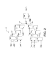
- FIG. 2 depicts a stability detection block diagram 200, according to example embodiments of the invention.
- Embodiments of the invention may utilize a variable guide vane (VGV) command 202 and a fuel stroke reference (FSR) command 222 and as inputs.
- VV variable guide vane
- FSR fuel stroke reference
- fuel and air may be considered main variables that respond to grid fluctuations, load changes and other disturbances to the turbine.
- fuel and air commands can be processed to determine stability before there is a relatively significant change in parameters such as exhaust temperature, pyrometer temperatures, spreads or wattage output of the turbine.
- the stability detection block diagram 200 includes a number of inputs for receiving commands and variables, and several blocks for processing the inputs.
- inputs related to the variable guide vane may include a VGV command 202, a VGV lag time constant 204, a VGV moving average time constant 206, and a VGV stability threshold 214.
- inputs related to the fuel stroke reference may include a FSR command 222, a FSR lag time constant 224, a FSR moving average time constant 226, and a FSR stability threshold 234.
- the VGV command 202 may be fed into a first order lag block 208 and a moving average block 210.
- a VGV lag time constant 204 may be utilized to set the parameters of the first order lag block 208, and a VGV moving average time constant 206 may be used to set the time constant for the moving average block 210.
- the VGV lag output 209 may be based at least in part on the VGV lag time constant 204 ranging from about 15 seconds to about 300 seconds.
- the VGV command 202 may also be processed by the moving average block 210 according to the VGV moving average time constant 206, resulting in a VGV moving average output 211.
- the VGV moving average output 211 may be based at least in part on the VGV moving average time constant 206 ranging from about 0.25 seconds to about 5 seconds.
- the VGV lag output 209, and the VGV moving average output 211 may be compared by block 212 to obtain an absolute value of the difference between the inputs, and the resulting VGV difference 215 may be used as input to an evaluation block 216, and compared to a VGV stability threshold 214.
- the VGV stability threshold 214 may range from about 0.25 degrees to about 3 degrees.
- the first order lag may be a slowly varying signal that may provide a moving reference for which to compare the quickly moving changes in the moving average signal.
- FSR command 222 may be fed into a first order lag block 228 and a moving average block 230.
- a FSR lag time constant 224 may be utilized to set the parameters of the first order lag block 228, and a FSR moving average time constant 226 may be used to set the time constant for the moving average block 230.
- the FSR command 222 may also be processed by the moving average block 230 according to the FSR moving average time constant 226, resulting in a FSR moving average output 231.
- the FSR moving average 231 may be based at least in part on a FSR moving average time constant 226 ranging from about 0.25 seconds to about 5 seconds.
- the FSR lag output 229 may be based at least in part on a FSR lag time constant 224 ranging from about 15 seconds to about 300 seconds.
- the FSR lag output 229 and the FSR moving average output 231 may be compared by block 232 to obtain an absolute value of the difference between the inputs, and the resulting FSR difference 235 may be used as input to an evaluation block 236, and compared to a FSR stability threshold 234. For example, if the difference between the FSR lag output 229 and the FSR moving average output 231 is less than the FSR stability threshold 234, then a logic true FSR stability signal 238 may be generated by the evaluation block 236.
- the FSR stability threshold 234 may range from about 0.25 percent to about 4 percent.
- an AND block 220 may be utilized to evaluate the VGV stability signal 218 and the FSR stability signal 238. If both of these signals are logic true, then the output of the AND block 220 may go true, indicating unit stability.
- an additional variable delay block 240 may be utilized to de-bounce or further delay the unit stability signal 244 going true (after the AND block 220 has produced a true output) until after a certain variable pickup time delay 242 has elapsed.
- the variable pickup delay time 242 may be set based upon the mode of protection for the unit, or upon parameters such as exhaust temperature, pyrometer temperatures, spreads or wattage output of the turbine. In certain example embodiments of the invention, the pickup delay time 242 may ranges from about 30 seconds to about 10 minutes.
- FIG. 3 depicts a block diagram of turbine stability detection control system 300, according to an example embodiment of the invention.
- the system 300 may include a controller 302, which may include a memory 304, one or more processors 306, and input/output interfaces 308.
- the controller 302 may include one or more network interfaces 310.
- the memory 304 may include an operating system 312, data 314, and various special purpose modules.
- the turbine stability detection control system 300 may receive signals from various sensors 320, and may be utilized to sending control signals to the turbine controls 324.
- a database 322 may communicate with the controller 302 to store and retrieve data or processing variables.
- the memory 302 may include a stability module 316 (such as 112 in FIG. 1 ) configured or programmed to carry out operations including comparisons, logic, delays, and other functions as previously discussed with reference to FIG. 2 .
- the memory 304 may also include a protection module 318 (which can be similar to 108 in FIG. 1 .)
- the protection module 318 may receive information from the stability module 316 or sensors 320, and may utilize this information in conjunction with instructions from a stability module 316 to initiate shutdown of the turbine when certain criteria are met. For example, the stability module 318 may monitor the output of the stability module 316 to determine if the turbine has reached steady state operation.
- the stability module 316 may inhibit the protection module 318 and keep it from initiating a shutdown of the system via the turbine controls 324 until after the stability criteria are met, and/or certain event criteria have been met. For example, shutdown may be initiated upon detection of the event and after fuel and/or guide vane commands associated with the turbine have stabilized.
- the method 400 starts in block 402, where according to an example embodiment of the invention, the method 400 includes receiving a guide vane (VGV) command and a fuel stroke reference (FSR) command associated with a gas turbine control system.
- VGV guide vane
- FSR fuel stroke reference
- the method 400 includes determining a filtered VGV change based at least in part on the received VGV command.
- the method 400 includes determining a filtered FSR change based at least in part on the received FSR command.
- the method 400 includes outputting a unit stability signal after a pickup delay time when the filtered VGV change is less than a predetermined VGV stability threshold and the filtered FSR change is less than a predetermined FSR stability threshold. The method 400 ends after block 408.
- example embodiments of the invention can provide the technical effects of creating certain systems, methods, and apparatus that provide detection of stability associated with a turbine.
- Example embodiments of the invention can provide the further technical effects of providing systems, methods, and apparatus for detecting stability of a turbine based on fuel commands and/or guide vane commands associated with the turbine.
- Example embodiments of the invention can provide the further technical effects of providing systems, methods, and apparatus for avoiding unnecessary shutdown of a turbine during startup.
- the turbine stability detection system 100 and/or the turbine stability detection control system 300 may include any number of hardware and/or software applications that are executed to facilitate any of the operations.
- one or more I/O interfaces may facilitate communication between the turbine stability detection system 100 and/or the turbine stability detection control system 300, and one or more input/output devices.
- a universal serial bus port, a serial port, a disk drive, a CD-ROM drive, and/or one or more user interface devices such as a display, keyboard, keypad, mouse, control panel, touch screen display, microphone, etc.
- the one or more I/O interfaces may be utilized to receive or collect data and/or user instructions from a wide variety of input devices. Received data may be processed by one or more computer processors as desired in various embodiments of the invention and/or stored in one or more memory devices.
- One or more network interfaces may facilitate connection of the turbine stability detection system 100 and/or the turbine stability detection control system 300 inputs and outputs to one or more suitable networks and/or connections; for example, the connections that facilitate communication with any number of sensors associated with the system.
- the one or more network interfaces may further facilitate connection to one or more suitable networks; for example, a local area network, a wide area network, the Internet, a cellular network, a radio frequency network, a Bluetooth TM enabled network, a Wi-Fi TM enabled network, a satellite-based network, any wired network, any wireless network, etc., for communication with external devices and/or systems.
- embodiments of the invention may include the turbine stability detection system 100 and/or the turbine stability detection control system 300 with more or less of the components illustrated in FIGs. 1 and 3 .
- These computer-executable program instructions may be loaded onto a general-purpose computer, a special-purpose computer, a processor, or other programmable data processing apparatus to produce a particular machine, such that the instructions that execute on the computer, processor, or other programmable data processing apparatus create means for implementing one or more functions specified in the flow diagram block or blocks.
- These computer program instructions may also be stored in a computer-readable memory that can direct a computer or other programmable data processing apparatus to function in a particular manner, such that the instructions stored in the computer-readable memory produce an article of manufacture including instruction means that implement one or more functions specified in the flow diagram block or blocks.
- embodiments of the invention may provide for a computer program product, comprising a computer-usable medium having a computer-readable program code or program instructions embodied therein, said computer-readable program code adapted to be executed to implement one or more functions specified in the flow diagram block or blocks.
- the computer program instructions may also be loaded onto a computer or other programmable data processing apparatus to cause a series of operational elements or steps to be performed on the computer or other programmable apparatus to produce a computer-implemented process such that the instructions that execute on the computer or other programmable apparatus provide elements or steps for implementing the functions specified in the flow diagram block or blocks.
- blocks of the block diagrams and flow diagrams support combinations of means for performing the specified functions, combinations of elements or steps for performing the specified functions and program instruction means for performing the specified functions. It will also be understood that each block of the block diagrams and flow diagrams, and combinations of blocks in the block diagrams and flow diagrams, can be implemented by special-purpose, hardware-based computer systems that perform the specified functions, elements or steps, or combinations of special-purpose hardware and computer instructions.
Landscapes
- Engineering & Computer Science (AREA)
- Chemical & Material Sciences (AREA)
- Combustion & Propulsion (AREA)
- Physics & Mathematics (AREA)
- Fluid Mechanics (AREA)
- Mechanical Engineering (AREA)
- General Engineering & Computer Science (AREA)
- Control Of Turbines (AREA)
- Testing And Monitoring For Control Systems (AREA)
Abstract
Description
- This invention generally relates to gas turbines, and in particular, to determining steady state conditions associated with the turbine.
- Gas turbines are typically large, complex, and expensive machines that operate under challenging environmental conditions. Building, maintaining, and operating these machines often requires a significant capital investment, and therefore, steps are often taken to ramp-up and ramp-down the turbines under careful control, in order to protect the capital investment, and operate the turbine within safe limits.
- When a turbine is being ramped-up and brought on-line, certain parameters such as exhaust temperature, power output, airflow, and fuel flow, for example, can be measured to provide feedback for stabilizing the turbine. Such measured parameters may also be used to detect anomalous behavior or dangerous operating conditions that may require corrective action to avoid a costly malfunction. In many cases, the delay or lag time between the turbine operational variables and the associated measurable parameters may be too long to reliably and/or effectively act upon.
- Some or all of the above needs may be addressed by certain embodiments of the invention. Certain embodiments of the invention may include systems, methods, and apparatus for determining steady state conditions associated with the turbine.
- According to an example embodiment of the invention, a method for determining stability in a gas turbine is provided. The method can include receiving a guide vane (VGV) command and a fuel stroke reference (FSR) command associated with a gas turbine control system, determining a filtered VGV change based at least in part on the received VGV command, determining a filtered FSR change based at least in part on the received FSR command, and outputting a unit stability signal after a pickup delay time when the filtered VGV change is less than a predetermined VGV stability threshold and the filtered FSR change is less than a predetermined FSR stability threshold.
- According to another example embodiment, a system is provided for determining stability. The system can include a gas turbine, at least one memory for storing data and computer-executable instructions, and at least one processor configured to access the at least one memory. The at least one processor is further configured to execute the computer-executable instructions for receiving a guide vane (VGV) command and a fuel stroke reference (FSR) command associated with the gas turbine, determining a filtered VGV change based at least in part on the received VGV command, determining a filtered FSR change based at least in part on the received FSR command, and outputting a unit stability signal after a pickup delay time when the filtered VGV change is less than a predetermined VGV stability threshold and the filtered FSR change is less than a predetermined FSR stability threshold.
- According to another example embodiment, an apparatus is provided for determining stability in a gas turbine. The apparatus can include at least one memory for storing data and computer-executable instructions. The apparatus can also include at least one processor configured to access the at least one memory and further configured to execute the computer-executable instructions for receiving a guide vane (VGV) command and a fuel stroke reference (FSR) command associated with a gas turbine, determining a filtered VGV change based at least in part on the received VGV command, determining a filtered FSR change based at least in part on the received FSR command, and outputting a unit stability signal after a pickup delay time when the filtered VGV change is less than a predetermined VGV stability threshold and the filtered FSR change is less than a predetermined FSR stability threshold.
- Other embodiments and aspects of the invention are described in detail herein and are considered a part of the claimed inventions. Other embodiments and aspects can be understood with reference to the following detailed description, accompanying drawings, and claims.
- Reference will now be made to the accompanying tables and drawings, which are not necessarily drawn to scale, and wherein:
-
FIG. 1 is a block diagram of an illustrative turbine stability detection system according to an example embodiment of the invention. -
FIG. 2 is an example stability detection block diagram according to an example embodiment of the invention. -
FIG. 3 is a turbine stability detection control system according to an example embodiment of the invention. -
FIG. 4 is a flow diagram of an example method according to an example embodiment of the invention. - Embodiments of the invention will be described more fully hereinafter with reference to the accompanying drawings, in which embodiments of the invention are shown. This invention may, however, be embodied in many different forms and should not be construed as limited to the embodiments set forth herein; rather, these embodiments are provided so that this disclosure will be thorough and complete, and will fully convey the scope of the invention to those skilled in the art. Like numbers refer to like elements throughout. Certain embodiments of the invention may enable determining steady state conditions in a gas turbine. According to example embodiments, certain control commands may be monitored to detect turbine stability.
- In certain example embodiments of the invention, monitoring control commands instead of feedback parameters, for example, may provide certain advantages for determining if a turbine has reached stability or steady state. Feedback parameters such as exhaust temperature, power output, airflow, or fuel flow, for example, could be measured to provide feedback for determining the stability of the turbine. However, in many cases, there may be too long of a delay between the turbine operational variable and the associated measurable feedback parameters for the feedback to be responsive and/or effective. As an example, exhaust temperature may be one variable to consider as a variable for determining turbine stability. However, the turbine may actually be operating under stable condition minutes before such stability is reflected in the exhaust temperature. Therefore, according to example embodiments of the invention, commands associated with the fuel and guide vanes may be utilized a more direct measure of the turbine stability.
- In certain example embodiments of the invention, turbine protection algorithms may need to know if the unit is at steady state before enabling their protection. Some of these algorithms may need be disabled before disturbances appear on output parameters such as pyrometer temperatures. According to example embodiments of the invention, a stability algorithm is provided. According to example embodiments, the algorithm may be robust and accurate enough to prevent false protective actions, and it may be fast enough to ensure stability is confirmed or disabled before certain output parameters are significantly affected.
- According to example embodiments of the invention, various sensors, signal processors, stability detection modules, and controllers for detecting turbine stability will now be described with reference to the accompanying figures.
-
FIG. 1 is a block diagram illustrating an example turbinestability detection system 100, according to example embodiments of the invention. Thesystem 100 may include one or more sensor(s) 102 for measuring parameters, and/or events associated with the turbine. In an example embodiment, thesensors 102 may include linear variable differential transformers (LVDTs), pyrometer sensors, emissivity sensors, temperature sensors, gas sensors, pressure sensors, cameras, acoustical sensors, etc. Thesystem 100 may also include one or moredata capture modules 104 that may be configured to receive and condition the parameter information measured by thesensors 102. Thedata capture modules 104 may include analog to digital converters, level shifting, filtering, calibration, power supplies, etc., for proper communication with thesensors 102 and/or for conditioning the signals received from thesensors 102. - According to an example embodiment, the data capture module(s) 104 may communicate with a signal-
processing module 106. In an example embodiment the signal-processing module 106 may further process the information received from the sensor(s) 102 via the data capture module(s) 104. For example, the signal-processing module 106 may average or filter the incoming data. In certain embodiments, the signal-processing module 106 may scale and/or format the data. - In certain example embodiments of the invention, some of the various operational modes of the gas turbine may be more suitable than others for determining events associated with possible failure. For example, when the turbine is being ramped-up, the measurable parameters (temperature, exhaust gasses, airflow, fuel flow, etc.) may be fluctuating normally, but may cause a false alarm or shutdown of the system. Therefore, according to an aspect of one embodiment of the invention, a
stability detection 112 module may monitorturbine commands 110 to enable aprotection module 108 only after certain criteria are met. For example, thestability detection module 112 may monitorturbine commands 110 to determine if the turbine has reached steady state operation, and/or if other criteria are met. In accordance with an example embodiment of the invention, thestability detection module 112 may inhibit theprotection module 108 and keep it from initiating a shutdown of the system via theturbine controls 114 until after the stability criteria are met. For example, shutdown may be initiated upon detection of an event and after turbine has initialized or stabilized. - According to example embodiments of the invention,
turbine commands 110 such as a variable guide vane (VGV) command or a fuel stroke reference (FSR) command may be monitored and utilized to determine stability of the turbine. In certain example embodiments of the invention, thestability detection block 112 may accept multiple inputs and variable parameters, thresholds, etc. for determining the stability of the turbine. -
FIG. 2 depicts a stability detection block diagram 200, according to example embodiments of the invention. Embodiments of the invention may utilize a variable guide vane (VGV)command 202 and a fuel stroke reference (FSR)command 222 and as inputs. According to example embodiments, fuel and air may be considered main variables that respond to grid fluctuations, load changes and other disturbances to the turbine. In certain example embodiments, fuel and air commands can be processed to determine stability before there is a relatively significant change in parameters such as exhaust temperature, pyrometer temperatures, spreads or wattage output of the turbine. In accordance with an example embodiment of the invention, the stability detection block diagram 200 includes a number of inputs for receiving commands and variables, and several blocks for processing the inputs. According to an example embodiment of the invention, inputs related to the variable guide vane (VGV) may include aVGV command 202, a VGVlag time constant 204, a VGV movingaverage time constant 206, and aVGV stability threshold 214. According to an example embodiment of the invention, inputs related to the fuel stroke reference (FSR) may include aFSR command 222, a FSRlag time constant 224, a FSR movingaverage time constant 226, and aFSR stability threshold 234. - In accordance with an example embodiment of the invention, the
VGV command 202 may be fed into a firstorder lag block 208 and a movingaverage block 210. A VGVlag time constant 204 may be utilized to set the parameters of the firstorder lag block 208, and a VGV moving average time constant 206 may be used to set the time constant for the movingaverage block 210. According to example embodiments of the invention, the firstorder lag block 208 may process theinput VGV command 202, and theVGV lag output 209 may be based at least in part on the following Laplace transform: Y(s) = 1/ (τ*s +1), where τ is equal to the VGVlag time constant 204. In accordance with certain example embodiments of the invention, theVGV lag output 209 may be based at least in part on the VGV lag time constant 204 ranging from about 15 seconds to about 300 seconds. - In certain example embodiments of the invention, the
VGV command 202 may also be processed by the movingaverage block 210 according to the VGV movingaverage time constant 206, resulting in a VGV movingaverage output 211. According to an example embodiment, the VGV movingaverage output 211 may be based at least in part on the VGV movingaverage time constant 206 ranging from about 0.25 seconds to about 5 seconds. In an example embodiment, theVGV lag output 209, and the VGV movingaverage output 211 may be compared byblock 212 to obtain an absolute value of the difference between the inputs, and the resultingVGV difference 215 may be used as input to anevaluation block 216, and compared to aVGV stability threshold 214. For example, if the difference between theVGV lag output 209 and the VGV movingaverage output 211 is less than theVGV stability threshold 214, then a logic highVGV stability signal 218 may be generated by theevaluation block 216. In certain example embodiments, theVGV stability threshold 214 may range from about 0.25 degrees to about 3 degrees. In certain embodiments of the invention, the first order lag may be a slowly varying signal that may provide a moving reference for which to compare the quickly moving changes in the moving average signal. - An analogous process as described above may be carried out for the fuel stroke reference (FSR)
command 222. For example,FSR command 222 may be fed into a firstorder lag block 228 and a movingaverage block 230. A FSRlag time constant 224 may be utilized to set the parameters of the firstorder lag block 228, and a FSR movingaverage time constant 226 may be used to set the time constant for the movingaverage block 230. According to example embodiments of the invention, the firstorder lag block 228 may process theinput FSR command 222, and theFSR lag output 229 may be based at least in part on the following Laplace transform: Y(s) = 1/ (τ*s +1), where τ is equal to the FSRlag time constant 224. TheFSR command 222 may also be processed by the movingaverage block 230 according to the FSR movingaverage time constant 226, resulting in a FSR movingaverage output 231. In an example embodiment, theFSR moving average 231 may be based at least in part on a FSR movingaverage time constant 226 ranging from about 0.25 seconds to about 5 seconds. In an example embodiment, theFSR lag output 229 may be based at least in part on a FSR lag time constant 224 ranging from about 15 seconds to about 300 seconds. In an example embodiment, theFSR lag output 229 and the FSR movingaverage output 231 may be compared byblock 232 to obtain an absolute value of the difference between the inputs, and the resultingFSR difference 235 may be used as input to anevaluation block 236, and compared to aFSR stability threshold 234. For example, if the difference between theFSR lag output 229 and the FSR movingaverage output 231 is less than theFSR stability threshold 234, then a logic trueFSR stability signal 238 may be generated by theevaluation block 236. In certain example embodiments of the invention, theFSR stability threshold 234 may range from about 0.25 percent to about 4 percent. - According to example embodiments, an AND block 220 may be utilized to evaluate the
VGV stability signal 218 and theFSR stability signal 238. If both of these signals are logic true, then the output of the AND block 220 may go true, indicating unit stability. In accordance with an example embodiment of the invention, an additionalvariable delay block 240 may be utilized to de-bounce or further delay theunit stability signal 244 going true (after the AND block 220 has produced a true output) until after a certain variablepickup time delay 242 has elapsed. In accordance with example embodiments of the invention, the variablepickup delay time 242 may be set based upon the mode of protection for the unit, or upon parameters such as exhaust temperature, pyrometer temperatures, spreads or wattage output of the turbine. In certain example embodiments of the invention, thepickup delay time 242 may ranges from about 30 seconds to about 10 minutes. -
FIG. 3 depicts a block diagram of turbine stabilitydetection control system 300, according to an example embodiment of the invention. According to an example embodiment, thesystem 300 may include acontroller 302, which may include a memory 304, one ormore processors 306, and input/output interfaces 308. In certain example embodiments, thecontroller 302 may include one or more network interfaces 310. In an example embodiment, the memory 304 may include anoperating system 312,data 314, and various special purpose modules. In example embodiments of the invention, the turbine stabilitydetection control system 300 may receive signals fromvarious sensors 320, and may be utilized to sending control signals to the turbine controls 324. In an example embodiment, adatabase 322 may communicate with thecontroller 302 to store and retrieve data or processing variables. - In an example embodiment, the
memory 302 may include a stability module 316 (such as 112 inFIG. 1 ) configured or programmed to carry out operations including comparisons, logic, delays, and other functions as previously discussed with reference toFIG. 2 . According to an example embodiment, the memory 304 may also include a protection module 318 (which can be similar to 108 inFIG. 1 .) Theprotection module 318 may receive information from thestability module 316 orsensors 320, and may utilize this information in conjunction with instructions from astability module 316 to initiate shutdown of the turbine when certain criteria are met. For example, thestability module 318 may monitor the output of thestability module 316 to determine if the turbine has reached steady state operation. In accordance with an example embodiment of the invention, thestability module 316 may inhibit theprotection module 318 and keep it from initiating a shutdown of the system via the turbine controls 324 until after the stability criteria are met, and/or certain event criteria have been met. For example, shutdown may be initiated upon detection of the event and after fuel and/or guide vane commands associated with the turbine have stabilized. - An example method for detecting stability in a gas turbine will now be described with reference to the flowchart of
FIG. 4 . Themethod 400 starts inblock 402, where according to an example embodiment of the invention, themethod 400 includes receiving a guide vane (VGV) command and a fuel stroke reference (FSR) command associated with a gas turbine control system. Inblock 404, themethod 400 includes determining a filtered VGV change based at least in part on the received VGV command. Inblock 406, themethod 400 includes determining a filtered FSR change based at least in part on the received FSR command. Inblock 408, themethod 400 includes outputting a unit stability signal after a pickup delay time when the filtered VGV change is less than a predetermined VGV stability threshold and the filtered FSR change is less than a predetermined FSR stability threshold. Themethod 400 ends afterblock 408. - Accordingly, example embodiments of the invention can provide the technical effects of creating certain systems, methods, and apparatus that provide detection of stability associated with a turbine. Example embodiments of the invention can provide the further technical effects of providing systems, methods, and apparatus for detecting stability of a turbine based on fuel commands and/or guide vane commands associated with the turbine. Example embodiments of the invention can provide the further technical effects of providing systems, methods, and apparatus for avoiding unnecessary shutdown of a turbine during startup.
- In example embodiments of the invention, the turbine
stability detection system 100 and/or the turbine stabilitydetection control system 300 may include any number of hardware and/or software applications that are executed to facilitate any of the operations. - In example embodiments, one or more I/O interfaces may facilitate communication between the turbine
stability detection system 100 and/or the turbine stabilitydetection control system 300, and one or more input/output devices. For example, a universal serial bus port, a serial port, a disk drive, a CD-ROM drive, and/or one or more user interface devices, such as a display, keyboard, keypad, mouse, control panel, touch screen display, microphone, etc., may facilitate user interaction with the turbinestability detection system 100 and/or the turbine stabilitydetection control system 300. The one or more I/O interfaces may be utilized to receive or collect data and/or user instructions from a wide variety of input devices. Received data may be processed by one or more computer processors as desired in various embodiments of the invention and/or stored in one or more memory devices. - One or more network interfaces may facilitate connection of the turbine
stability detection system 100 and/or the turbine stabilitydetection control system 300 inputs and outputs to one or more suitable networks and/or connections; for example, the connections that facilitate communication with any number of sensors associated with the system. The one or more network interfaces may further facilitate connection to one or more suitable networks; for example, a local area network, a wide area network, the Internet, a cellular network, a radio frequency network, a BluetoothTM enabled network, a Wi-FiTM enabled network, a satellite-based network, any wired network, any wireless network, etc., for communication with external devices and/or systems. - As desired, embodiments of the invention may include the turbine
stability detection system 100 and/or the turbine stabilitydetection control system 300 with more or less of the components illustrated inFIGs. 1 and3 . - The invention is described above with reference to block and flow diagrams of systems, methods, apparatuses, and/or computer program products according to example embodiments of the invention. It will be understood that one or more blocks of the block diagrams and flow diagrams, and combinations of blocks in the block diagrams and flow diagrams, respectively, can be implemented by computer-executable program instructions. Likewise, some blocks of the block diagrams and flow diagrams may not necessarily need to be performed in the order presented, or may not necessarily need to be performed at all, according to some embodiments of the invention.
- These computer-executable program instructions may be loaded onto a general-purpose computer, a special-purpose computer, a processor, or other programmable data processing apparatus to produce a particular machine, such that the instructions that execute on the computer, processor, or other programmable data processing apparatus create means for implementing one or more functions specified in the flow diagram block or blocks. These computer program instructions may also be stored in a computer-readable memory that can direct a computer or other programmable data processing apparatus to function in a particular manner, such that the instructions stored in the computer-readable memory produce an article of manufacture including instruction means that implement one or more functions specified in the flow diagram block or blocks. As an example, embodiments of the invention may provide for a computer program product, comprising a computer-usable medium having a computer-readable program code or program instructions embodied therein, said computer-readable program code adapted to be executed to implement one or more functions specified in the flow diagram block or blocks. The computer program instructions may also be loaded onto a computer or other programmable data processing apparatus to cause a series of operational elements or steps to be performed on the computer or other programmable apparatus to produce a computer-implemented process such that the instructions that execute on the computer or other programmable apparatus provide elements or steps for implementing the functions specified in the flow diagram block or blocks.
- Accordingly, blocks of the block diagrams and flow diagrams support combinations of means for performing the specified functions, combinations of elements or steps for performing the specified functions and program instruction means for performing the specified functions. It will also be understood that each block of the block diagrams and flow diagrams, and combinations of blocks in the block diagrams and flow diagrams, can be implemented by special-purpose, hardware-based computer systems that perform the specified functions, elements or steps, or combinations of special-purpose hardware and computer instructions.
- While the invention has been described in connection with what is presently considered to be the most practical and various embodiments, it is to be understood that the invention is not to be limited to the disclosed embodiments, but on the contrary, is intended to cover various modifications and equivalent arrangements included within the scope of the appended claims. Although specific terms are employed herein, they are used in a generic and descriptive sense only and not for purposes of limitation.
- This written description uses examples to disclose the invention, including the preferred mode, and also to enable any person skilled in the art to practice the invention, including making and using any devices or systems and performing any incorporated methods. The patentable scope of the invention is defined in the claims, and may include other examples that occur to those skilled in the art. Such other examples are intended to be within the scope of the claims if they have structural elements that do not differ from the literal language of the claims, or if they include equivalent structural elements with insubstantial differences from the literal language of the claims.
- Various aspects and embodiments of the present invention are defined by the following numbered clauses:
- 1. A method for determining stability in a gas turbine, comprising:
- receiving a guide vane (VGV) command and a fuel stroke reference (FSR) command associated with a gas turbine control system;
- determining a filtered VGV change based at least in part on the received VGV command;
- determining a filtered FSR change based at least in part on the received FSR command; and,
- outputting a unit stability signal after a pickup delay time when the filtered VGV change is less than a predetermined VGV stability threshold and the filtered FSR change is less than a predetermined FSR stability threshold.
- 2. The method of clause 1, wherein determining the filtered VGV change comprises determining a difference between a VGV lag and a VGV moving average, and wherein determining the filtered FSR change comprises determining a difference between an FSR lag and an FSR moving average.
- 3. The method of any preceding clause, wherein the VGV lag is based at least in part on a VGV lag time constant ranging from about 15 seconds to about 300 seconds, and wherein the VGV moving average is based at least in part on a VGV moving average time constant ranging from about 0.25 seconds to about 5 seconds.
- 4. The method of any preceding clause, wherein the FSR lag is based at least in part on a FSR lag time constant ranging from about 15 seconds to about 300 seconds, and wherein the FSR moving average is based at least in part on a FSR moving average time constant ranging from about 0.25 seconds to about 5 seconds.
- 5. The method of any preceding clause, wherein the VGV lag and the FSR lag are first order lags based on the following equation: Y(s) = 1/ (τ*s +1) where τ is equal to the FSR or VGV lag time constant.
- 6. The method of any preceding clause, wherein the VGV stability threshold ranges from about 0.25 degrees to about 3 degrees.
- 7. The method of any preceding clause, wherein the FSR stability threshold ranges from about 0.25 percent to about 4 percent.
- 8. The method of any preceding clause, wherein the pickup delay time ranges from about 30 seconds to about 10 minutes and is selectable based at least in part on a protection mode.
- 9. A system for determining stability, comprising:
- a gas turbine;
- at least one memory for storing data and computer-executable instructions; and,
- at least one processor configured to access the at least one memory and further configured to execute the computer-executable instructions for:
- receiving a guide vane (VGV) command and a fuel stroke reference (FSR) command associated with the gas turbine;
- determining a filtered VGV change based at least in part on the received VGV command;
- determining a filtered FSR change based at least in part on the received FSR command; and,
- outputting a unit stability signal after a pickup delay time when the filtered VGV change is less than a predetermined VGV stability threshold and the filtered FSR change is less than a predetermined FSR stability threshold.
- 10. The system of any preceding clause, wherein the at least one processor is further configured to determine a filtered VGV change comprising a difference between a VGV lag and a VGV moving average, and wherein the at least one processor is further configured to determine a filtered FSR change comprising a difference between a FSR lag and a FSR moving average.
- 11. The system of any preceding clause, wherein the VGV lag is based at least in part on a VGV lag time constant ranging from about 15 seconds to about 300 seconds, and wherein the VGV moving average is based at least in part on a VGV moving average time constant ranging from about 0.25 seconds to about 5 seconds.
- 12. The system of any preceding clause, wherein the FSR lag is based at least in part on a FSR lag time constant ranging from about 15 seconds to about 300 seconds, and wherein the FSR moving average is based at least in part on a FSR moving average time constant ranging from about 0.25 seconds to about 5 seconds.
- 13. The system of any preceding clause, wherein the at least one processor is further configured to determine the VGV lag and the FSR lag based at least in part on the following equation: Y(s) = 1/ (τ*s +1) where τ is equal to the FSR or VGV lag time constant.
- 14. The system of any preceding clause, wherein the VGV stability threshold ranges from about 0.25 degrees to about 3 degrees, and wherein the FSR stability threshold ranges from about 0.25 percent to about 4 percent.
- 15. The system of any preceding clause, wherein the pickup delay time ranges from about 30 seconds to about 10 minutes and is selectable based at least in part on a protection mode.
- 16. An apparatus for determining stability in a gas turbine, comprising:
- at least one memory for storing data and computer-executable instructions; and,
- at least one processor configured to access the at least one memory and further configured to execute the computer-executable instructions for:
- receiving a guide vane (VGV) command and a fuel stroke reference (FSR) command associated with a gas turbine;
- determining a filtered VGV change based at least in part on the received VGV command;
- determining a filtered FSR change based at least in part on the received FSR command; and,
- outputting a unit stability signal after a pickup delay time when the filtered VGV change is less than a predetermined VGV stability threshold and the filtered FSR change is less than a predetermined FSR stability threshold.
- 17. The apparatus of any preceding clause, wherein the at least one processor is further configured to determine a filtered VGV change comprising a difference between a VGV lag and a VGV moving average, and wherein the at least one processor is further configured to determine a filtered FSR change comprising a difference between a FSR lag and a FSR moving average, and wherein the VGV lag is based at least in part on a VGV lag time constant ranging from about 15 seconds to about 300 seconds, and wherein the VGV moving average is based at least in part on a VGV moving average time constant ranging from about 0.25 seconds to about 5 seconds, and wherein the FSR lag is based at least in part on a FSR lag time constant ranging from about 15 seconds to about 300 seconds, and wherein the FSR moving average is based at least in part on a FSR moving average time constant ranging from about 0.25 seconds to about 5 seconds.
- 18. The apparatus of any preceding clause, wherein the at least one processor is further configured to determine the VGV lag and the FSR lag based at least in part on the following equation: Y(s) = 1/ (τ*s +1) where τ is equal to the FSR or VGV lag time constant.
- 19. The apparatus of any preceding clause, wherein the VGV stability threshold ranges from about 0.25 degrees to about 3 degrees, and wherein the FSR stability threshold ranges from about 0.25 percent to about 4 percent.
- 20. The apparatus of any preceding clause, wherein the pickup delay time ranges from about 30 seconds to about 10 minutes and is selectable based at least in part on a protection mode.
Claims (10)
- A method for determining stability in a gas turbine, comprising:receiving a guide vane (VGV) command (202) and a fuel stroke reference (FSR) command (222) associated with a gas turbine control system (300);determining a filtered VGV change (215) based at least in part on the received VGV command (202);determining a filtered FSR change (235) based at least in part on the received FSR command (222); andoutputting a unit stability signal (244) after a pickup delay time (242) when the filtered VGV change (215) is less than a predetermined VGV stability threshold (215) and the filtered FSR change (235) is less than a predetermined FSR stability threshold (234).
- The method of claim 1, wherein determining the filtered VGV change (215) comprises determining a difference between a VGV lag (209) and a VGV moving average (211), and wherein determining the filtered FSR change (235) comprises determining a difference between an FSR lag (229) and an FSR moving average (231).
- The method of any preceding claim, wherein the VGV lag (209) is based at least in part on a VGV lag time constant (204) ranging from about 15 seconds to about 300 seconds, and wherein the VGV moving average (211) is based at least in part on a VGV moving average time constant (206) ranging from about 0.25 seconds to about 5 seconds.
- The method of any preceding claim, wherein the FSR lag (229) is based at least in part on an FSR lag time constant (224) ranging from about 15 seconds to about 300 seconds, and wherein the FSR moving average (231) is based at least in part on an FSR moving average time constant (226) ranging from about 0.25 seconds to about 5 seconds.
- The method of any preceding claim, wherein the VGV lag (209) and the FSR lag (229) are first order lags based on the following equation: Y(s) = 1/ (τ*s +1) where τ is equal to the FSR or VGV lag time constant.
- The method of any preceding claim, wherein the VGV stability threshold (215) ranges from about 0.25 degrees to about 3 degrees.
- The method of any preceding claim, wherein the FSR stability threshold (234) ranges from about 0.25 percent to about 4 percent.
- The method of any preceding claim, wherein the pickup delay time (242) ranges from about 30 seconds to about 10 minutes and is selectable based at least in part on a protection mode.
- A system for determining stability, comprising:a gas turbine;at least one memory (304) for storing data (314) and computer-executable instructions; and,at least one processor (306) configured to access the at least one memory (304) and further configured to execute the computer-executable instructions for:receiving a guide vane (VGV) command (202) and a fuel stroke reference (FSR) command (222) associated with the gas turbine;determining a filtered VGV change (215) based at least in part on the received VGV command (202);determining a filtered FSR change (235) based at least in part on the received FSR command (222); and,outputting a unit stability signal (244) after a pickup delay time (242) when the filtered VGV change (215) is less than a predetermined VGV stability threshold (215) and the filtered FSR change (235) is less than a predetermined FSR stability threshold (234).
- The system of claim 9, wherein the at least one processor (306) is further configured to determine a filtered VGV change (215) comprising a difference between a VGV lag (209) and a VGV moving average (211), and wherein the at least one processor (306) is further configured to determine a filtered FSR change (235) comprising a difference between an FSR lag (229) and an FSR moving average (231).
Applications Claiming Priority (1)
| Application Number | Priority Date | Filing Date | Title |
|---|---|---|---|
| US12/834,929 US8285516B2 (en) | 2010-07-13 | 2010-07-13 | Systems, methods, and apparatus for determining steady state conditions in a gas turbine |
Publications (3)
| Publication Number | Publication Date |
|---|---|
| EP2407642A2 true EP2407642A2 (en) | 2012-01-18 |
| EP2407642A3 EP2407642A3 (en) | 2015-05-27 |
| EP2407642B1 EP2407642B1 (en) | 2016-11-30 |
Family
ID=44510037
Family Applications (1)
| Application Number | Title | Priority Date | Filing Date |
|---|---|---|---|
| EP11172741.8A Active EP2407642B1 (en) | 2010-07-13 | 2011-07-05 | System and method for determining steady state conditions in a gas turbine |
Country Status (4)
| Country | Link |
|---|---|
| US (1) | US8285516B2 (en) |
| EP (1) | EP2407642B1 (en) |
| JP (1) | JP5404699B2 (en) |
| CN (1) | CN102330608B (en) |
Cited By (1)
| Publication number | Priority date | Publication date | Assignee | Title |
|---|---|---|---|---|
| EP3876059A1 (en) * | 2020-03-04 | 2021-09-08 | General Electric Company | Systems, program products, and methods for detecting thermal stability within gas turbine systems |
Families Citing this family (3)
| Publication number | Priority date | Publication date | Assignee | Title |
|---|---|---|---|---|
| US20180189398A1 (en) * | 2014-02-23 | 2018-07-05 | Iot Holdings, Inc. | Cognitive and affective human machine interface |
| EP3056814A1 (en) * | 2015-02-13 | 2016-08-17 | General Electric Technology GmbH | Method of controlling the fuel distribution among different stages of a gas turbine combustion chamber |
| US11803168B2 (en) | 2019-03-08 | 2023-10-31 | General Electric Company | Distributed control modules with cumulating command references |
Family Cites Families (12)
| Publication number | Priority date | Publication date | Assignee | Title |
|---|---|---|---|---|
| JPS6380022A (en) * | 1986-09-22 | 1988-04-11 | Nissan Motor Co Ltd | Controller for gas turbine |
| JP2855619B2 (en) * | 1988-07-27 | 1999-02-10 | トヨタ自動車株式会社 | Control device for twin-shaft gas turbine engine |
| JP2897348B2 (en) * | 1990-06-06 | 1999-05-31 | トヨタ自動車株式会社 | Shift control method for gas turbine vehicle |
| US5487265A (en) * | 1994-05-02 | 1996-01-30 | General Electric Company | Gas turbine coordinated fuel-air control method and apparatus therefor |
| JP4639480B2 (en) * | 2001-01-30 | 2011-02-23 | 日産自動車株式会社 | Diesel engine control device |
| US6719526B2 (en) * | 2002-08-23 | 2004-04-13 | General Electric Company | Method for categorizing the operating mode of a gas turbine |
| JP2006291762A (en) * | 2005-04-07 | 2006-10-26 | Honda Motor Co Ltd | Operation control device for gas turbine engine |
| US7668704B2 (en) * | 2006-01-27 | 2010-02-23 | Ricardo, Inc. | Apparatus and method for compressor and turbine performance simulation |
| US7457688B2 (en) | 2006-09-19 | 2008-11-25 | General Electric Company | Method and system for detection and transfer to electrical island operation |
| US7730724B2 (en) * | 2007-05-10 | 2010-06-08 | Ford Global Technologies, Llc | Turbocharger shaft over-speed compensation |
| US8255140B2 (en) * | 2008-10-01 | 2012-08-28 | GM Global Technology Operations LLC | Thermal-protection based engine performance enhancement |
| US7941281B2 (en) * | 2008-12-22 | 2011-05-10 | General Electric Company | System and method for rotor blade health monitoring |
-
2010
- 2010-07-13 US US12/834,929 patent/US8285516B2/en active Active
-
2011
- 2011-07-05 JP JP2011148829A patent/JP5404699B2/en active Active
- 2011-07-05 EP EP11172741.8A patent/EP2407642B1/en active Active
- 2011-07-13 CN CN201110210938.2A patent/CN102330608B/en not_active Expired - Fee Related
Non-Patent Citations (1)
| Title |
|---|
| None |
Cited By (2)
| Publication number | Priority date | Publication date | Assignee | Title |
|---|---|---|---|---|
| EP3876059A1 (en) * | 2020-03-04 | 2021-09-08 | General Electric Company | Systems, program products, and methods for detecting thermal stability within gas turbine systems |
| US11585234B2 (en) | 2020-03-04 | 2023-02-21 | General Electric Company | Systems, program products, and methods for detecting thermal stability within gas turbine systems |
Also Published As
| Publication number | Publication date |
|---|---|
| JP5404699B2 (en) | 2014-02-05 |
| CN102330608A (en) | 2012-01-25 |
| CN102330608B (en) | 2015-07-22 |
| US8285516B2 (en) | 2012-10-09 |
| JP2012021527A (en) | 2012-02-02 |
| US20120016636A1 (en) | 2012-01-19 |
| EP2407642B1 (en) | 2016-11-30 |
| EP2407642A3 (en) | 2015-05-27 |
Similar Documents
| Publication | Publication Date | Title |
|---|---|---|
| US10650613B2 (en) | Systems and methods for monitoring protection devices of an industrial machine | |
| EP2378087B1 (en) | System and method for detecting failure in gas turbine | |
| EP1376285B1 (en) | Trouble detection method, trouble detection apparatus, and temperature controller | |
| US7632059B2 (en) | Systems and methods for detecting undesirable operation of a turbine | |
| EP1826364B1 (en) | Method for determining limit exceedance | |
| US8285516B2 (en) | Systems, methods, and apparatus for determining steady state conditions in a gas turbine | |
| CN107607987B (en) | Gas kitchen ranges | |
| JP2019096289A (en) | Abnormality detector, abnormality detection method, abnormality detection program, and abnormality detection system | |
| TW201736997A (en) | Control apparatus for rotating device | |
| CN119755512B (en) | Intelligent explosion-proof pressure relief hydrogen storage cylinder and control method thereof | |
| JP5675456B2 (en) | Monitoring device, gas turbine plant, and gas turbine monitoring method | |
| CN102252850B (en) | For detecting the system of the fault in gas turbine hardware, method and apparatus | |
| US11397135B2 (en) | Method of detecting flameout in a combustor and turbine system | |
| CN120160125B (en) | Boiler fault detection method, device, equipment, storage medium and computer program product | |
| US20180266270A1 (en) | Method of detecting flameout in a combustor and turbine system |
Legal Events
| Date | Code | Title | Description |
|---|---|---|---|
| AK | Designated contracting states |
Kind code of ref document: A2 Designated state(s): AL AT BE BG CH CY CZ DE DK EE ES FI FR GB GR HR HU IE IS IT LI LT LU LV MC MK MT NL NO PL PT RO RS SE SI SK SM TR |
|
| AX | Request for extension of the european patent |
Extension state: BA ME |
|
| PUAI | Public reference made under article 153(3) epc to a published international application that has entered the european phase |
Free format text: ORIGINAL CODE: 0009012 |
|
| PUAL | Search report despatched |
Free format text: ORIGINAL CODE: 0009013 |
|
| AK | Designated contracting states |
Kind code of ref document: A3 Designated state(s): AL AT BE BG CH CY CZ DE DK EE ES FI FR GB GR HR HU IE IS IT LI LT LU LV MC MK MT NL NO PL PT RO RS SE SI SK SM TR |
|
| AX | Request for extension of the european patent |
Extension state: BA ME |
|
| RIC1 | Information provided on ipc code assigned before grant |
Ipc: F02C 9/28 20060101ALI20150423BHEP Ipc: G05B 23/02 20060101ALI20150423BHEP Ipc: F02C 9/54 20060101ALI20150423BHEP Ipc: F01D 17/16 20060101AFI20150423BHEP |
|
| 17P | Request for examination filed |
Effective date: 20151127 |
|
| RBV | Designated contracting states (corrected) |
Designated state(s): AL AT BE BG CH CY CZ DE DK EE ES FI FR GB GR HR HU IE IS IT LI LT LU LV MC MK MT NL NO PL PT RO RS SE SI SK SM TR |
|
| RIC1 | Information provided on ipc code assigned before grant |
Ipc: G05B 23/02 20060101ALI20160419BHEP Ipc: F02C 9/54 20060101ALI20160419BHEP Ipc: F01D 17/16 20060101AFI20160419BHEP Ipc: F02C 9/28 20060101ALI20160419BHEP |
|
| GRAP | Despatch of communication of intention to grant a patent |
Free format text: ORIGINAL CODE: EPIDOSNIGR1 |
|
| INTG | Intention to grant announced |
Effective date: 20160531 |
|
| GRAJ | Information related to disapproval of communication of intention to grant by the applicant or resumption of examination proceedings by the epo deleted |
Free format text: ORIGINAL CODE: EPIDOSDIGR1 |
|
| GRAP | Despatch of communication of intention to grant a patent |
Free format text: ORIGINAL CODE: EPIDOSNIGR1 |
|
| INTC | Intention to grant announced (deleted) | ||
| GRAS | Grant fee paid |
Free format text: ORIGINAL CODE: EPIDOSNIGR3 |
|
| INTG | Intention to grant announced |
Effective date: 20160928 |
|
| GRAA | (expected) grant |
Free format text: ORIGINAL CODE: 0009210 |
|
| AK | Designated contracting states |
Kind code of ref document: B1 Designated state(s): AL AT BE BG CH CY CZ DE DK EE ES FI FR GB GR HR HU IE IS IT LI LT LU LV MC MK MT NL NO PL PT RO RS SE SI SK SM TR |
|
| REG | Reference to a national code |
Ref country code: CH Ref legal event code: EP Ref country code: GB Ref legal event code: FG4D |
|
| REG | Reference to a national code |
Ref country code: AT Ref legal event code: REF Ref document number: 850000 Country of ref document: AT Kind code of ref document: T Effective date: 20161215 |
|
| REG | Reference to a national code |
Ref country code: IE Ref legal event code: FG4D |
|
| REG | Reference to a national code |
Ref country code: DE Ref legal event code: R096 Ref document number: 602011032851 Country of ref document: DE |
|
| PG25 | Lapsed in a contracting state [announced via postgrant information from national office to epo] |
Ref country code: LV Free format text: LAPSE BECAUSE OF FAILURE TO SUBMIT A TRANSLATION OF THE DESCRIPTION OR TO PAY THE FEE WITHIN THE PRESCRIBED TIME-LIMIT Effective date: 20161130 |
|
| REG | Reference to a national code |
Ref country code: LT Ref legal event code: MG4D |
|
| REG | Reference to a national code |
Ref country code: NL Ref legal event code: MP Effective date: 20161130 |
|
| REG | Reference to a national code |
Ref country code: AT Ref legal event code: MK05 Ref document number: 850000 Country of ref document: AT Kind code of ref document: T Effective date: 20161130 |
|
| PG25 | Lapsed in a contracting state [announced via postgrant information from national office to epo] |
Ref country code: GR Free format text: LAPSE BECAUSE OF FAILURE TO SUBMIT A TRANSLATION OF THE DESCRIPTION OR TO PAY THE FEE WITHIN THE PRESCRIBED TIME-LIMIT Effective date: 20170301 Ref country code: SE Free format text: LAPSE BECAUSE OF FAILURE TO SUBMIT A TRANSLATION OF THE DESCRIPTION OR TO PAY THE FEE WITHIN THE PRESCRIBED TIME-LIMIT Effective date: 20161130 Ref country code: LT Free format text: LAPSE BECAUSE OF FAILURE TO SUBMIT A TRANSLATION OF THE DESCRIPTION OR TO PAY THE FEE WITHIN THE PRESCRIBED TIME-LIMIT Effective date: 20161130 Ref country code: NO Free format text: LAPSE BECAUSE OF FAILURE TO SUBMIT A TRANSLATION OF THE DESCRIPTION OR TO PAY THE FEE WITHIN THE PRESCRIBED TIME-LIMIT Effective date: 20170228 |
|
| PG25 | Lapsed in a contracting state [announced via postgrant information from national office to epo] |
Ref country code: FI Free format text: LAPSE BECAUSE OF FAILURE TO SUBMIT A TRANSLATION OF THE DESCRIPTION OR TO PAY THE FEE WITHIN THE PRESCRIBED TIME-LIMIT Effective date: 20161130 Ref country code: HR Free format text: LAPSE BECAUSE OF FAILURE TO SUBMIT A TRANSLATION OF THE DESCRIPTION OR TO PAY THE FEE WITHIN THE PRESCRIBED TIME-LIMIT Effective date: 20161130 Ref country code: PL Free format text: LAPSE BECAUSE OF FAILURE TO SUBMIT A TRANSLATION OF THE DESCRIPTION OR TO PAY THE FEE WITHIN THE PRESCRIBED TIME-LIMIT Effective date: 20161130 Ref country code: RS Free format text: LAPSE BECAUSE OF FAILURE TO SUBMIT A TRANSLATION OF THE DESCRIPTION OR TO PAY THE FEE WITHIN THE PRESCRIBED TIME-LIMIT Effective date: 20161130 Ref country code: PT Free format text: LAPSE BECAUSE OF FAILURE TO SUBMIT A TRANSLATION OF THE DESCRIPTION OR TO PAY THE FEE WITHIN THE PRESCRIBED TIME-LIMIT Effective date: 20170330 Ref country code: AT Free format text: LAPSE BECAUSE OF FAILURE TO SUBMIT A TRANSLATION OF THE DESCRIPTION OR TO PAY THE FEE WITHIN THE PRESCRIBED TIME-LIMIT Effective date: 20161130 Ref country code: ES Free format text: LAPSE BECAUSE OF FAILURE TO SUBMIT A TRANSLATION OF THE DESCRIPTION OR TO PAY THE FEE WITHIN THE PRESCRIBED TIME-LIMIT Effective date: 20161130 |
|
| PG25 | Lapsed in a contracting state [announced via postgrant information from national office to epo] |
Ref country code: NL Free format text: LAPSE BECAUSE OF FAILURE TO SUBMIT A TRANSLATION OF THE DESCRIPTION OR TO PAY THE FEE WITHIN THE PRESCRIBED TIME-LIMIT Effective date: 20161130 |
|
| PG25 | Lapsed in a contracting state [announced via postgrant information from national office to epo] |
Ref country code: CZ Free format text: LAPSE BECAUSE OF FAILURE TO SUBMIT A TRANSLATION OF THE DESCRIPTION OR TO PAY THE FEE WITHIN THE PRESCRIBED TIME-LIMIT Effective date: 20161130 Ref country code: SK Free format text: LAPSE BECAUSE OF FAILURE TO SUBMIT A TRANSLATION OF THE DESCRIPTION OR TO PAY THE FEE WITHIN THE PRESCRIBED TIME-LIMIT Effective date: 20161130 Ref country code: DK Free format text: LAPSE BECAUSE OF FAILURE TO SUBMIT A TRANSLATION OF THE DESCRIPTION OR TO PAY THE FEE WITHIN THE PRESCRIBED TIME-LIMIT Effective date: 20161130 Ref country code: EE Free format text: LAPSE BECAUSE OF FAILURE TO SUBMIT A TRANSLATION OF THE DESCRIPTION OR TO PAY THE FEE WITHIN THE PRESCRIBED TIME-LIMIT Effective date: 20161130 Ref country code: RO Free format text: LAPSE BECAUSE OF FAILURE TO SUBMIT A TRANSLATION OF THE DESCRIPTION OR TO PAY THE FEE WITHIN THE PRESCRIBED TIME-LIMIT Effective date: 20161130 |
|
| PG25 | Lapsed in a contracting state [announced via postgrant information from national office to epo] |
Ref country code: BE Free format text: LAPSE BECAUSE OF FAILURE TO SUBMIT A TRANSLATION OF THE DESCRIPTION OR TO PAY THE FEE WITHIN THE PRESCRIBED TIME-LIMIT Effective date: 20161130 Ref country code: BG Free format text: LAPSE BECAUSE OF FAILURE TO SUBMIT A TRANSLATION OF THE DESCRIPTION OR TO PAY THE FEE WITHIN THE PRESCRIBED TIME-LIMIT Effective date: 20170228 Ref country code: SM Free format text: LAPSE BECAUSE OF FAILURE TO SUBMIT A TRANSLATION OF THE DESCRIPTION OR TO PAY THE FEE WITHIN THE PRESCRIBED TIME-LIMIT Effective date: 20161130 |
|
| REG | Reference to a national code |
Ref country code: DE Ref legal event code: R097 Ref document number: 602011032851 Country of ref document: DE |
|
| PLBE | No opposition filed within time limit |
Free format text: ORIGINAL CODE: 0009261 |
|
| STAA | Information on the status of an ep patent application or granted ep patent |
Free format text: STATUS: NO OPPOSITION FILED WITHIN TIME LIMIT |
|
| PGFP | Annual fee paid to national office [announced via postgrant information from national office to epo] |
Ref country code: IT Payment date: 20170725 Year of fee payment: 7 |
|
| 26N | No opposition filed |
Effective date: 20170831 |
|
| PG25 | Lapsed in a contracting state [announced via postgrant information from national office to epo] |
Ref country code: SI Free format text: LAPSE BECAUSE OF FAILURE TO SUBMIT A TRANSLATION OF THE DESCRIPTION OR TO PAY THE FEE WITHIN THE PRESCRIBED TIME-LIMIT Effective date: 20161130 |
|
| GBPC | Gb: european patent ceased through non-payment of renewal fee |
Effective date: 20170705 |
|
| REG | Reference to a national code |
Ref country code: IE Ref legal event code: MM4A |
|
| REG | Reference to a national code |
Ref country code: FR Ref legal event code: ST Effective date: 20180330 |
|
| PG25 | Lapsed in a contracting state [announced via postgrant information from national office to epo] |
Ref country code: IE Free format text: LAPSE BECAUSE OF NON-PAYMENT OF DUE FEES Effective date: 20170705 Ref country code: GB Free format text: LAPSE BECAUSE OF NON-PAYMENT OF DUE FEES Effective date: 20170705 |
|
| PG25 | Lapsed in a contracting state [announced via postgrant information from national office to epo] |
Ref country code: FR Free format text: LAPSE BECAUSE OF NON-PAYMENT OF DUE FEES Effective date: 20170731 |
|
| PG25 | Lapsed in a contracting state [announced via postgrant information from national office to epo] |
Ref country code: LU Free format text: LAPSE BECAUSE OF NON-PAYMENT OF DUE FEES Effective date: 20170705 |
|
| PG25 | Lapsed in a contracting state [announced via postgrant information from national office to epo] |
Ref country code: MT Free format text: LAPSE BECAUSE OF NON-PAYMENT OF DUE FEES Effective date: 20170705 |
|
| PG25 | Lapsed in a contracting state [announced via postgrant information from national office to epo] |
Ref country code: HU Free format text: LAPSE BECAUSE OF FAILURE TO SUBMIT A TRANSLATION OF THE DESCRIPTION OR TO PAY THE FEE WITHIN THE PRESCRIBED TIME-LIMIT; INVALID AB INITIO Effective date: 20110705 Ref country code: MC Free format text: LAPSE BECAUSE OF FAILURE TO SUBMIT A TRANSLATION OF THE DESCRIPTION OR TO PAY THE FEE WITHIN THE PRESCRIBED TIME-LIMIT Effective date: 20161130 |
|
| PG25 | Lapsed in a contracting state [announced via postgrant information from national office to epo] |
Ref country code: IT Free format text: LAPSE BECAUSE OF NON-PAYMENT OF DUE FEES Effective date: 20180705 |
|
| PGFP | Annual fee paid to national office [announced via postgrant information from national office to epo] |
Ref country code: CH Payment date: 20190624 Year of fee payment: 9 |
|
| PG25 | Lapsed in a contracting state [announced via postgrant information from national office to epo] |
Ref country code: CY Free format text: LAPSE BECAUSE OF NON-PAYMENT OF DUE FEES Effective date: 20161130 |
|
| PG25 | Lapsed in a contracting state [announced via postgrant information from national office to epo] |
Ref country code: MK Free format text: LAPSE BECAUSE OF FAILURE TO SUBMIT A TRANSLATION OF THE DESCRIPTION OR TO PAY THE FEE WITHIN THE PRESCRIBED TIME-LIMIT Effective date: 20161130 |
|
| PG25 | Lapsed in a contracting state [announced via postgrant information from national office to epo] |
Ref country code: TR Free format text: LAPSE BECAUSE OF FAILURE TO SUBMIT A TRANSLATION OF THE DESCRIPTION OR TO PAY THE FEE WITHIN THE PRESCRIBED TIME-LIMIT Effective date: 20161130 |
|
| PG25 | Lapsed in a contracting state [announced via postgrant information from national office to epo] |
Ref country code: AL Free format text: LAPSE BECAUSE OF FAILURE TO SUBMIT A TRANSLATION OF THE DESCRIPTION OR TO PAY THE FEE WITHIN THE PRESCRIBED TIME-LIMIT Effective date: 20161130 Ref country code: IS Free format text: LAPSE BECAUSE OF FAILURE TO SUBMIT A TRANSLATION OF THE DESCRIPTION OR TO PAY THE FEE WITHIN THE PRESCRIBED TIME-LIMIT Effective date: 20170330 |
|
| REG | Reference to a national code |
Ref country code: CH Ref legal event code: PL |
|
| PG25 | Lapsed in a contracting state [announced via postgrant information from national office to epo] |
Ref country code: LI Free format text: LAPSE BECAUSE OF NON-PAYMENT OF DUE FEES Effective date: 20200731 Ref country code: CH Free format text: LAPSE BECAUSE OF NON-PAYMENT OF DUE FEES Effective date: 20200731 |
|
| REG | Reference to a national code |
Ref country code: DE Ref legal event code: R081 Ref document number: 602011032851 Country of ref document: DE Owner name: GENERAL ELECTRIC TECHNOLOGY GMBH, CH Free format text: FORMER OWNER: GENERAL ELECTRIC COMPANY, SCHENECTADY, NY, US |
|
| PGFP | Annual fee paid to national office [announced via postgrant information from national office to epo] |
Ref country code: DE Payment date: 20250620 Year of fee payment: 15 |