EP2407634A2 - Irregularly shaped flapper closure and sealing surfaces - Google Patents
Irregularly shaped flapper closure and sealing surfaces Download PDFInfo
- Publication number
- EP2407634A2 EP2407634A2 EP20110167655 EP11167655A EP2407634A2 EP 2407634 A2 EP2407634 A2 EP 2407634A2 EP 20110167655 EP20110167655 EP 20110167655 EP 11167655 A EP11167655 A EP 11167655A EP 2407634 A2 EP2407634 A2 EP 2407634A2
- Authority
- EP
- European Patent Office
- Prior art keywords
- flapper
- tool
- rim
- seat
- flow tube
- Prior art date
- Legal status (The legal status is an assumption and is not a legal conclusion. Google has not performed a legal analysis and makes no representation as to the accuracy of the status listed.)
- Granted
Links
- 238000007789 sealing Methods 0.000 title claims abstract description 52
- 230000000295 complement effect Effects 0.000 claims 2
- 230000001788 irregular Effects 0.000 description 12
- 238000010586 diagram Methods 0.000 description 8
- 239000012530 fluid Substances 0.000 description 6
- 231100001261 hazardous Toxicity 0.000 description 4
- 230000009286 beneficial effect Effects 0.000 description 3
- 230000003247 decreasing effect Effects 0.000 description 3
- 230000015572 biosynthetic process Effects 0.000 description 2
- 230000007246 mechanism Effects 0.000 description 2
- 230000004075 alteration Effects 0.000 description 1
- 230000008859 change Effects 0.000 description 1
- 230000000694 effects Effects 0.000 description 1
- 239000000463 material Substances 0.000 description 1
- 230000013011 mating Effects 0.000 description 1
- 230000004048 modification Effects 0.000 description 1
- 238000012986 modification Methods 0.000 description 1
- 230000007704 transition Effects 0.000 description 1
Images



Classifications
-
- E—FIXED CONSTRUCTIONS
- E21—EARTH OR ROCK DRILLING; MINING
- E21B—EARTH OR ROCK DRILLING; OBTAINING OIL, GAS, WATER, SOLUBLE OR MELTABLE MATERIALS OR A SLURRY OF MINERALS FROM WELLS
- E21B34/00—Valve arrangements for boreholes or wells
- E21B34/06—Valve arrangements for boreholes or wells in wells
- E21B34/10—Valve arrangements for boreholes or wells in wells operated by control fluid supplied from outside the borehole
- E21B34/102—Valve arrangements for boreholes or wells in wells operated by control fluid supplied from outside the borehole with means for locking the closing element in open or closed position
-
- E—FIXED CONSTRUCTIONS
- E21—EARTH OR ROCK DRILLING; MINING
- E21B—EARTH OR ROCK DRILLING; OBTAINING OIL, GAS, WATER, SOLUBLE OR MELTABLE MATERIALS OR A SLURRY OF MINERALS FROM WELLS
- E21B34/00—Valve arrangements for boreholes or wells
- E21B34/06—Valve arrangements for boreholes or wells in wells
- E21B34/10—Valve arrangements for boreholes or wells in wells operated by control fluid supplied from outside the borehole
-
- E—FIXED CONSTRUCTIONS
- E21—EARTH OR ROCK DRILLING; MINING
- E21B—EARTH OR ROCK DRILLING; OBTAINING OIL, GAS, WATER, SOLUBLE OR MELTABLE MATERIALS OR A SLURRY OF MINERALS FROM WELLS
- E21B2200/00—Special features related to earth drilling for obtaining oil, gas or water
- E21B2200/05—Flapper valves
-
- Y—GENERAL TAGGING OF NEW TECHNOLOGICAL DEVELOPMENTS; GENERAL TAGGING OF CROSS-SECTIONAL TECHNOLOGIES SPANNING OVER SEVERAL SECTIONS OF THE IPC; TECHNICAL SUBJECTS COVERED BY FORMER USPC CROSS-REFERENCE ART COLLECTIONS [XRACs] AND DIGESTS
- Y10—TECHNICAL SUBJECTS COVERED BY FORMER USPC
- Y10T—TECHNICAL SUBJECTS COVERED BY FORMER US CLASSIFICATION
- Y10T137/00—Fluid handling
- Y10T137/7722—Line condition change responsive valves
- Y10T137/7837—Direct response valves [i.e., check valve type]
- Y10T137/7898—Pivoted valves
Definitions
- SCSSVs Surface-controlled, subsurface safety valves
- the SCSSV fits onto production tubing in a well and operates to block flow of formation fluid upwardly through the tubing should a failure or hazardous condition occur at the well surface.
- the SCSSV can be tubing retrievable and rigidly connected to the production tubing (tubing retrievable), or it can be wireline retrievable and installed and retrieved by wireline without disturbing the production tubing.
- SCSSVs are "normally closed” and use a flapper type closure mechanism biased to a closed position.
- a hydraulic actuator can be moved longitudinally in the SCSSV to overcome the flapper's bias and open the valve.
- the actuator uses a piston and a flow tube.
- the SCSSV provides automatic shutoff of the production flow.
- the hazardous condition can be sensed and/or indicated at the surface or elsewhere and can include a fire on the platform, a high/low flow line pressure condition, a high/low flow line temperature condition, operator override, or the like.
- the hydraulic pressure is removed from the control line, and the loss of hydraulic pressure causes the flapper to close and block the flow of production fluids up the tubing.
- the flapper closes (as well as opens), the flapper's mating surface engages with the flow tube.
- the conventional flapper has a concentrated area on its inside surface that engages with the flow tube as they both moving during closing (or opening). This area and even the flapper's sealing surface can be damaged or deformed during harsh opening and closing operations.
- the direct solution to address the problem of damage to the flapper simply involves limiting the flow level for which the flapper mechanism is rated. Alternatively, the flapper's thickness can be increased to make it more robust, but this reduces the cross-sectional flow area that can pass through the valve. In any event, operators strive for valves providing as much flow area as possible when open and capable of operating in high working pressures. When operators need a valve with a very slim diameter, such as 7-in., addressing problems with damage to the flapper becomes even more problematic.
- the subject matter of the present disclosure is directed to overcoming, or at least reducing the effects of, one or more of the problems set forth above.
- a flapper valve for a downhole tool such as a surface controlled sub-surface safety valve, has a seat and a flapper.
- the seat has a seating rim and can be dispose in a housing's tubular bore.
- the flapper can pivot at a proximal end relative to the seat.
- the flapper has a sealing rim that corresponds in shape to the seating rim so that the two rims seal when mated together.
- the seating rim defines a first perimeter conforming to a circular profile, but the seating rim has an irregular shape having first lobes disposed outside the first perimeter.
- the flapper's sealing rim defines a second perimeter conforming to the first perimeter of the seating rim.
- the sealing rim also has second lobes disposed outside the second perimeter and disposed on either side of the flapper's proximal end about which it pivots.
- a flow tube of the downhole tool can move relative to the seat and the flapper.
- a biasing member biases this flow tube away from the flapper so that the flapper can close.
- a hydraulically actuated piston pushes the flow tube toward the flapper to open it when the piston is activated.
- the flapper When the flow tube moves away from the flapper, the flapper closes transverse to the tubular bore and engages the seat. When the flow tube moves towards the flapper, the flapper fits in a space between the flow tube and the tubular bore of the housing. In either case, the second lobes protect the flapper's sealing rim as the flapper's inside surface engages the moving flow tube.
- the flapper can be a curved flapper, a flat flapper, or a combination thereof, and the teachings of the present disclosure can apply to a flapper of any shape flapper, whether flat or curved.
- the lobes on the flapper can help protect its sealing rim when engaged by the moving flow tube.
- both the sealing and seating rims have an irregular contour in addition to the irregular perimeters with lobes.
- the seat's rim defines a first edge undulating transversely about the first perimeter.
- the flapper's rim defines a second edge undulating transversely about the second perimeter.
- the seating rim defines outcroppings that deviate outwardly from the transverse undulation of the first edge.
- the flapper's sealing rim defines incroppings at the second lobes that deviate inwardly from the transverse undulation of the second edge.
- the sealing and seating rims of the flapper valve can have a groove and a ridge disposed at least partially thereabout.
- the seating rim can have the groove disposed at least partially thereabout, while the sealing rim can have the ridge disposed at least partially thereabout.
- the groove and ridge can define triangular cross-sections, rectilinear cross-sections, or a combination of these.
- the ridge engages or fits in the groove to hold the flapper's rim in place.
- Use of the grooves and ridges can be beneficial to any shaped flapper, whether flat, curved, or combination thereof.
- a downhole tool comprising:
- a flapper closure comprising:
- a downhole tool comprising:
- the seating rim may comprise the groove disposed at least partially thereabout, and the sealing rim may comprises the ridge disposed at least partially thereabout.
- the groove and ridge may define triangular cross-sections, rectilinear cross-sections, or a combination of cross-sections.
- the flapper may have a curved inside surface.
- a flapper closure comprising:
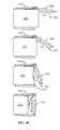
- FIG. 1 is a partial cross-section of a downhole tool having a flapper valve according to the present disclosure.
- FIGS. 2A-2B are isolated perspective views of the flapper valve according to the present disclosure.
- FIGS. 3A-3F show top, distal end, back, proximal end, right, and left views of the flapper.
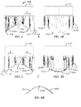
- FIG. 4A diagrams a plan view of the flapper's perimeter.
- FIG. 4B diagrams a side view of the flapper's edge.
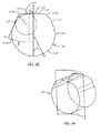
- FIG. 4C shows a closing operation of the flapper valve.
- FIG. 4D is a plan view of the flapper's inside surface.
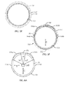
- FIG. 4E diagrams another plan view of the flapper's perimeter.
- FIG. 4F shows the flapper's perimeter projected onto a curved plane.
- FIGS. 5A-5F show left, front, right, back, top, and bottom views of the seat.
- FIG. 6A diagrams a plan view of the seat's perimeter.
- FIG. 6B diagrams a side view of the seat's edge.
- FIG. 7 is a detailed view of the sealing edge of the flapper.
- FIGS. 8A-8E show various profiles for the flapper's sealing edge.
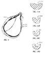
- FIG. 9 is a detailed view of the sealing edge of the seat.
- FIGS. 10A-10D show various profiles for the seat's sealing edge.
- FIG. 1 shows a partial cross-section of a downhole tool 10 having a flapper valve 50 according to the present disclosure.
- the tool 10 can be a surface-controlled, subsurface safety valve (SCSSV) for shutting-in a well.
- SCSSV subsurface safety valve
- the tool 10 can fit into or onto production tubing (not shown) in the well and can operate to block flow of formation fluid through the production tubing should a failure or hazardous condition occur.
- the flapper valve 50 can also be used in other downhole tools, such as a downhole deployment valve (DDV), a downhole control valve (DCV), or other downhole valve or closure.
- DDV downhole deployment valve
- DCV downhole control valve
- the tool 10 has a through-bore 12 for passage of production fluid.
- a control line 14 from the surface supplies hydraulic fluid to a chamber 16 in the tool 10, and hydraulic pressure in the chamber 16 moves a piston 20 against the bias of a spring 35. Coupled to this piston 20, a flow tube 30 moves in the tool's through-bore 12.
- the flow tube 30 opens the flapper valve 50 by pivoting a flapper 100 away from a seat 150.
- the flapper 100 fits in an annular space 18 between the flow tube 30 and the tool's housing. In this position, the flow tube 30 helps convey production fluids through the tool 10 while protecting the flapper valve 50.
- the flapper 100 is maintained open by hydraulic pressure applied to the piston 20, which moves the flow tube 30 against the bias of the spring 35 to open the flapper 100. Any loss of hydraulic pressure at the control line 14 causes the piston 20 and actuated flow tube 30 to retract. This causes the flapper 100 to return to its normally closed position.
- the spring 35 biases the piston 20 and flow tube 30 upward in the through-bore 12. Freed, the flapper 100 pivots on a hinged connection to the seat 150 by a torsion spring (64; Fig. 1 ) or the like until the flapper 100 seals against the seat 150 and closes flow up through the tool's bore 12.
- FIGS 3A-3B show the flapper valve 50 in a closed condition.
- the seat 150 has a narrow end 152 and a widened end 154 and fits inside the tool's housing.
- the flapper 100 connects to the seat 150 with a hinge bracket 60 on the widened end 154 using fasteners 62. When closed, the flapper 100 covers the seat 150 and blocks flow therethrough.
- the movement of the flow tube 30 and pivoting of the flapper 100 can be quite sudden and hard. Therefore, the components are made to withstand hard closings. Yet, as the flow tube 30 moves and frees the flapper 100 to pivot, the flow tube 30 tends to rub along the top or inside surface of the flapper 100. Because the flapper 100 is curved, the flow tube 30 can damage various areas of the inside surface and even jeopardize the resultant seal that can be achieved with the flapper 100, especially when the flapper valve 50 undergoes several hard closures. The same problems can occur when opening the flapper 100. As the flow tube 30 forces the flapper 100 open, it tends to ride along the inside surface, which can cause damage.
- the flapper valve 50 of the present disclosure addresses this type of damage.
- the flapper 100 and seat 150 have irregular shapes that are different than what is conventionally used in the art.
- the flapper valve 50 can maintain the flow area through the tool 10. In this way, the flapper valve 50 can address damage to the flapper 100 while accounting for the scarcity of space in the downhole tool 10 and not decreasing the flow area through the tool 10.
- the flapper 100 has a curved body 102 that allows the flapper 100 to take the cylindrical profile of the tool's annular space (18) around the flow tube (30) when open. (See Fig. 1 .) This allows the tool 10 to remain slim while maximizing the flow area possible through the tool's bore 12.
- the flapper 100 can have a flat body or at least a flat outside surface 104. In this instance, the tool 10 may require a side pocket area for the flapper 100 to fit when pivoted open.
- the flapper's body 102 has a bottom or outside surface 104 (shown in Fig. 3C ) that closes off the downhole portion of the tool (10) when the flapper 100 is closed across the seat (150).
- the top or inside surface 106 (shown in Fig. 3A ) sits against the seat 150 when closed.
- the flow tube (30) engages this surface 106. Therefore, this surface 106 is where damage can occur due to hard opening and closings of the flapper 100.
- the flapper's inside surface 106 has a central ledge 108 circumscribed by a sealing rim 110. Because the flapper's body 102 closes across the cylindrical bore (12) of the tool (10), the profile of the flapper's body 102 is generally circular. Because the flapper's body 102 is cylindrically curved, the sealing rim 110 has a transverse undulating shape. This means that the flapper's edges 114a-b transverse to a centerline C undulate or fold inward at a different elevation than the edges 112/118 at the centerline C. As a result, the edges of the sealing rim 110 have a generally sinusoidal contour around the flapper 100.
- the contour of the flapper's edge and the profile of its perimeter are irregular to protect the inside surface 106 from damage by the flow tube (30) during hard openings and closings.
- the rim's distal edge 112 extending to the transverse edges 114a-b follows a sinusoidal contour.
- the rim's contour from the transverse edges 114a-b to the proximal edge 118 deviates from sinusoidal and has outcropped deviations 116a-b. (The contour of these outcropped deviations 116a-b relative to a sinusoidal contour is best shown in the diagram of FIG. 4B .)
- the distal perimeter 122 extending to the transverse perimeters 124a-b conform to a circle.
- the rim's profile from the transverse perimeters 124a-b to the proximal perimeter 128 deviates from circular and has outcropped lobes 126a-b. Between these lobes 126a-b, the proximal perimeter 128 is generally straight where the hinges 103 connect, and the perimeter 128 lies within the general circular profile of the rim's circular perimeter 120.
- angles for the arc from the distal perimeter 122 to the transverse perimeters 124a-b, the arc for the lobes 126a-b, and the arc for the straight perimeter 128 can vary depending on the implementation. Additionally, the angles for the arcs can depend on the overall diameter of the tool and other factors. In one arrangement, for example, the tool can have an overall diameter of 7-inches.
- the distal perimeter 122 to the transverse perimeters 124a-b can encompass an arc of about 230-degrees, while the lobes 126a-b can encompass arcs of about 52-degrees each. This leaves an arc of about 26-degrees for the straight, back perimeter 128. Again, these values are exemplary and can vary depending on the implementation.
- Figures 4E-4F show additional details of one arrangement for the flapper's perimeter 120.
- the distal perimeter 122 to the transverse perimeters 124a-b define a contour having a large radius R.
- Intermediate perimeters 125 between the transverse perimeters 124a-b and the lobes 126a-b define lines at an angle ⁇ relative to the flapper's centerline C.
- the lobes 126a-b themselves define a contour with a smaller radius R offset from the flapper's center.
- transition perimeters 127 define lines at an angle ⁇ relative to the flapper's centerline C.
- the angle ⁇ can be about 23-degrees, while the angle ⁇ can be about 95-degrees.
- the various dimensions (especially large radius R and length of the sections of the perimeter) for the flapper can vary depending on the implementation.
- FIG. 4F shows how flapper's perimeter 120 is projected onto a curved plane so that the flapper's rim has the transverse undulating shape described herein.
- the seat 150 has a narrow portion 152 and a widened portion 154. Both are generally cylindrical.
- the narrow portion 152 is cylindrical and has a cylindrical bore 153 for passage of the flow tube (30) therein.
- the widened portion 154 is also cylindrical and has a cylindrical bore 155 for passage of the flow tube (30) therein.
- the perimeter 120 of the flapper's rim 110 is irregularly shaped with the lobes 126a-b
- the perimeter 170 of the seat's rim 160 is complementarily shaped.
- the edge contours of the seating rim 160 deviate from the typically smooth transverse undulating contour that is generally sinusoidal.
- the seating rim 160 has an edge contour that mirrors the sealing rim 110 of the flapper 100 described previously. In this way, the two rims 110/160 can mate with one another to form a seal when the flapper 100 is closed against the seat 150. Accordingly, the seating rim 160 has a transverse undulating contour with the seat's edges 164a-b transverse to a centerline C undulate or fold inward at a different elevation than the edges 162/168 at the centerline C. As a result, the edges of the seating rim 160 are generally sinusoidal around the seat 150.
- the rim's distal edge 162 extending to the transverse edges 164a-b follows a sinusoidal contour.
- the rim's contour from the transverse edges 164a-b to the proximal edge 168 deviates from sinusoidal and has incropped deviations 166a-b.
- the contour of these incropped deviations 166a-b relative to a sinusoidal contour is shown in FIG. 6B .
- portions of the seating rim 160 at the transverse edges 164a-b and distal and proximal edges 162/168 are roughly perpendicular to an axis passing through the seat 150.
- portions of the seating rim 160 between the transverse edges 164a-b and distal and proximal edges 162/168 angle outward.
- areas of the sealing rim 110 at the edges 122/124a-b/126 of the flapper 110 are roughly perpendicular, while the areas between the edges 122/124a-b 128 on the flapper 100 angle inward.
- Other angular configurations are possible.
- the perimeter 170 of the seat's rim 160 is generally circular.
- the distal perimeter 172 extending to the transverse perimeters 174a-b conforms to a circle.
- the rim's profile from the transverse perimeters 174a-b to the proximal perimeter 178 deviates from circular and has outcropped lobes 176a-b.
- the proximal perimeter 178 is generally straight and lies within the general circular profile of the rim's perimeter 170.
- the arcs encompassed by the distal perimeter 172 to the transverse perimeters 174a-b, the lobes 126a-b, and the straight perimeter 128 can be the same as those for the flapper 100 shown in FIG. 4A .
- FIG. 4C shows the flow tube 30 moving relative to the flapper 100 and seat 150 shown in cross-section. As the flow tube 30 retracts through the seat 150, the end of the flow tube 30 rubs along the inside surface 106 before eventually engaging the ledge 108 and then releasing from the flapper's equalizing valve 107. The same occurs in the reverse when the flow tube 30 opens the flapper 100. This motion results in contact on an area 109 of the flapper's inside surface 106 as shown in Figure 4D .
- the irregular shaped flapper 100 and seat 150 allows the components to be slimmer and take up less space in the downhole tool 10. All the same, the arrangement can operate under greater working pressure and can resist damage during harsh operations.
- a typical flapper used with a smaller tubing size may be restricted to lower working pressures due to potential collapse or failure of the flapper.
- a downhole valve with a 7-in. diameter having a typical curved flapper seal may be restricted to operating in working pressures below 10-ksi. Because the irregular shape of the flapper 100 and seat 150 disclosed herein permit the flapper 100 to be slimmer, use of the flapper valve 50 with smaller tubing sizes may also be restricted to lower working pressures than desired.
- the flapper valve 50 uses a groove and ridge arrangement to improve the engagement between the sealing rim 110 and seating rim 160 of the flapper 100 and seat 150.
- the sealing rim 110 of the flapper 100 shown in detail in FIG. 7 has a ridge or lip 130 circumscribed thereabout, and the seating rim 160 of the seat 150 shown in detail in FIG. 9 has a groove or channel 180 circumscribed thereabout.
- the ridge 130 and groove 180 are preferably defined all the way around the rims 110, 160, but in other implementations they may only be partially defined around portions of the rims 110/160. Having the ridge 130 on the flapper's rim 110 may be preferred so it can be protected from flow when the flapper 100 is pivoted to an opened condition and concealed by the flow tube (30). However, the reverse arrangement can also be used. Thus, the flapper 100 can have a groove, and the seat 150 can have a ridge.
- the shape of the ridge 130 and groove 180 can vary. Generally, they can be "V"-shaped, can be symmetrical or not, and can angle from 1 ° to 90° or more.
- FIGS. 8A-8E show various profiles for grooves 132a-f. As shown in FIGS. 8A-8D , the ridges 132a-d can have a triangular or "V"-shaped cross-section. Alternatively as shown in FIG. 8E , the ridges 132e-f can have a rectilinear cross-section, although curved and other cross-sections could be used. The ridge's tips can be pointed as in 132a or blunted as in 132b. The inside or outside edges can have the same size and angle as in 132b and 132c, or they can have different sizes or angles as in 132a or 132d. These and other possibilities could be used.
- the groove 180 can be complimentary to the shape of the ridge 130.
- FIGS. 10A-10D show various profiles for grooves 182a-d.
- the grooves 182a-d can have a triangular or "V"-shaped cross-section as in 182a-b or rectilinear cross-section as in 182c-d.
- the grooves 182 can also have a curved or other cross-section.
- the groove's inner vertex can be blunted or pointed as in 182a-b.
- the inside or outside edges can have the same size and angle as in 182b, or they can have different sizes and angles as in 182a.
- the grooves 130 can also be rectilinear as in 182c-d and can have cut away lips. These and other possibilities could be used.
- each profile of the ridge 130 and groove 180 can be consistent around the rims 110/160, or they can change around the perimeter of the rims from one profile to another.
- the ridge 130 engages in the groove 180. This helps keep the rims 110/160 in place when sealing and enhances the seal produced between them. Moreover, the curved flapper 100 can experience forces at higher working pressures that may attempt to deform (flatten or fold) the flapper 100. Engagement between the ridge 130 and groove 180 can help reinforce the flapper 100 so it can keep its shape and resist flattening or folding. Consequently, the minimum yield strength of the flapper 100's material can be decreased while still permitting higher working pressures. Likewise, the thickness of the flapper 100 can be decreased due to the ridge and groove 130/180.
- the flapper 100 is a curved type flapper rather than a flat type flapper.
- the flapper 100 has a curved body 102 with its inside and outsides surfaces 104/106 conforming to a cylindrical contour so the flapper 100 can fit into an annular space 18 between the flow tube 30 and tool's housing when open.
- the teachings of the present disclosure can apply to a flapper of any shape, whether curved, flat, or a combination thereof. Therefore, the flapper 100 disclosed herein can have flat inside and outside surfaces 104/106, curved inside and outside surfaces 104/106, or a curved inside surface 106 with a flat outside surface 104 or vice versa.
- the flapper 100 can have a curved or flat body 102 with its inside surface 106 and its outside surface 104 being either curved or flat.
- the lobes 126a-b on the flapper 100 can help protect its sealing rim 110 when engaged by the moving flow tube 30.
- the features of the ridges 130 and grooves 180 can be beneficial in either instance.
- the irregular contour of the sealing and seating rims 110/160 including the transversely undulating edges and outcroppings/incroppings that deviate from the transverse undulation of the edge can be beneficial in addition to the irregular perimeter having the lobes 126a-b/176a-b and the ridges 130 and grooves 180.
Landscapes
- Life Sciences & Earth Sciences (AREA)
- Engineering & Computer Science (AREA)
- Geology (AREA)
- Mining & Mineral Resources (AREA)
- Physics & Mathematics (AREA)
- Environmental & Geological Engineering (AREA)
- Fluid Mechanics (AREA)
- General Life Sciences & Earth Sciences (AREA)
- Geochemistry & Mineralogy (AREA)
- Lift Valve (AREA)
- Earth Drilling (AREA)
Abstract
Description
- Surface-controlled, subsurface safety valves (SCSSVs) are commonly used to shut-in oil and gas wells. The SCSSV fits onto production tubing in a well and operates to block flow of formation fluid upwardly through the tubing should a failure or hazardous condition occur at the well surface. The SCSSV can be tubing retrievable and rigidly connected to the production tubing (tubing retrievable), or it can be wireline retrievable and installed and retrieved by wireline without disturbing the production tubing.
- Most SCSSVs are "normally closed" and use a flapper type closure mechanism biased to a closed position. A hydraulic actuator can be moved longitudinally in the SCSSV to overcome the flapper's bias and open the valve. Typically, the actuator uses a piston and a flow tube.
- During normal production, hydraulic pressure transmitted to the piston moves the flow tube longitudinally in the valve to keep the flapper open. The hydraulic pressure is commonly supplied by a control line run along the annulus between the production tubing and casing. When a hazardous condition occurs, the SCSSV provides automatic shutoff of the production flow. The hazardous condition can be sensed and/or indicated at the surface or elsewhere and can include a fire on the platform, a high/low flow line pressure condition, a high/low flow line temperature condition, operator override, or the like.
- Once the condition is sensed or indicated, the hydraulic pressure is removed from the control line, and the loss of hydraulic pressure causes the flapper to close and block the flow of production fluids up the tubing. When the flapper closes (as well as opens), the flapper's mating surface engages with the flow tube. In fact, the conventional flapper has a concentrated area on its inside surface that engages with the flow tube as they both moving during closing (or opening). This area and even the flapper's sealing surface can be damaged or deformed during harsh opening and closing operations.
- The direct solution to address the problem of damage to the flapper simply involves limiting the flow level for which the flapper mechanism is rated. Alternatively, the flapper's thickness can be increased to make it more robust, but this reduces the cross-sectional flow area that can pass through the valve. In any event, operators strive for valves providing as much flow area as possible when open and capable of operating in high working pressures. When operators need a valve with a very slim diameter, such as 7-in., addressing problems with damage to the flapper becomes even more problematic.
- The subject matter of the present disclosure is directed to overcoming, or at least reducing the effects of, one or more of the problems set forth above.
- A flapper valve for a downhole tool, such as a surface controlled sub-surface safety valve, has a seat and a flapper. The seat has a seating rim and can be dispose in a housing's tubular bore. The flapper can pivot at a proximal end relative to the seat. The flapper has a sealing rim that corresponds in shape to the seating rim so that the two rims seal when mated together.
- In particular, the seating rim defines a first perimeter conforming to a circular profile, but the seating rim has an irregular shape having first lobes disposed outside the first perimeter. The flapper's sealing rim defines a second perimeter conforming to the first perimeter of the seating rim. The sealing rim also has second lobes disposed outside the second perimeter and disposed on either side of the flapper's proximal end about which it pivots.
- A flow tube of the downhole tool can move relative to the seat and the flapper. A biasing member biases this flow tube away from the flapper so that the flapper can close. However, a hydraulically actuated piston pushes the flow tube toward the flapper to open it when the piston is activated.
- When the flow tube moves away from the flapper, the flapper closes transverse to the tubular bore and engages the seat. When the flow tube moves towards the flapper, the flapper fits in a space between the flow tube and the tubular bore of the housing. In either case, the second lobes protect the flapper's sealing rim as the flapper's inside surface engages the moving flow tube.
- The flapper can be a curved flapper, a flat flapper, or a combination thereof, and the teachings of the present disclosure can apply to a flapper of any shape flapper, whether flat or curved. For example, when the flapper is curved or flat, the lobes on the flapper can help protect its sealing rim when engaged by the moving flow tube. When the flapper has a curved body, both the sealing and seating rims have an irregular contour in addition to the irregular perimeters with lobes. In this instance, the seat's rim defines a first edge undulating transversely about the first perimeter. Similarly, the flapper's rim defines a second edge undulating transversely about the second perimeter. At the first lobes, the seating rim defines outcroppings that deviate outwardly from the transverse undulation of the first edge. The flapper's sealing rim defines incroppings at the second lobes that deviate inwardly from the transverse undulation of the second edge.
- As an alternative or in addition to the irregular perimeter and contour, the sealing and seating rims of the flapper valve can have a groove and a ridge disposed at least partially thereabout. For example, the seating rim can have the groove disposed at least partially thereabout, while the sealing rim can have the ridge disposed at least partially thereabout. The groove and ridge can define triangular cross-sections, rectilinear cross-sections, or a combination of these. When the sealing rim engages the seating rim as the flapper closes on the seat, the ridge engages or fits in the groove to hold the flapper's rim in place. Use of the grooves and ridges can be beneficial to any shaped flapper, whether flat, curved, or combination thereof.
- According to a first aspect of the present invention there is provided a downhole tool comprising:
- a seat having a seating rim disposed about an internal bore of the tool, the seating rim having a first perimeter conforming to a circular profile, the seating rim having first lobes disposed outside the first perimeter; and
- a flapper disposed in the tool and pivotable at a proximal end relative to the seat, the flapper having a sealing rim disposed about an inside surface, the sealing rim defining a second perimeter conforming to the first perimeter of the seating rim, the sealing rim having second lobes disposed outside the second perimeter and disposed on either side of the proximal end of the flapper.
- According to a second aspect there is provided a flapper closure, comprising:
- a seat defining a tubular bore therethrough and having a seating rim disposed thereabout, the seating rim defining a first perimeter conforming to a circle, the seating rim having first lobes disposed outside the first perimeter; and
- a flapper pivotable at a proximal end relative to the seat, the flapper having a sealing rim disposed about an inside surface, the sealing rim defining a second perimeter conforming to the first perimeter of the seating rim, the sealing rim having second lobes disposed outside the second perimeter and disposed on either side of the proximal end of the curved flapper.
- According to a third aspect there is provided a downhole tool, comprising:
- a housing defining a tubular bore therethrough;
- a seat disposed in the tubular bore and having a seating rim disposed thereabout; and a flapper connected in the bore at a first end and pivotable at the first end relative to the seat, the flapper having a sealing rim disposed thereabout,
- the sealing and seating rims comprising a groove and a ridge disposed at least partially thereabout, the ridge engaging the groove when the sealing rim engages the seating rim.
- In the tool according to the third aspect the seating rim may comprise the groove disposed at least partially thereabout, and the sealing rim may comprises the ridge disposed at least partially thereabout. The groove and ridge may define triangular cross-sections, rectilinear cross-sections, or a combination of cross-sections. The flapper may have a curved inside surface.
- According to a fourth aspect of the invention there is provided a flapper closure, comprising:
- a seat defining a tubular bore therethrough and having a seating rim disposed thereabout; and
- a flapper pivotable at a proximal end relative to the seat, the flapper having a sealing rim disposed thereabout,
- the sealing and seating rims comprising a groove and a ridge disposed at least partially thereabout, the ridge engaging in the groove when the sealing rim engages the seating rim.
- The foregoing summary is not intended to summarize each potential embodiment or every aspect of the present disclosure.
-
FIG. 1 is a partial cross-section of a downhole tool having a flapper valve according to the present disclosure. -
FIGS. 2A-2B are isolated perspective views of the flapper valve according to the present disclosure. -
FIGS. 3A-3F show top, distal end, back, proximal end, right, and left views of the flapper. -
FIG. 4A diagrams a plan view of the flapper's perimeter. -
FIG. 4B diagrams a side view of the flapper's edge. -
FIG. 4C shows a closing operation of the flapper valve. -
FIG. 4D is a plan view of the flapper's inside surface. -
FIG. 4E diagrams another plan view of the flapper's perimeter. -
FIG. 4F shows the flapper's perimeter projected onto a curved plane. -
FIGS. 5A-5F show left, front, right, back, top, and bottom views of the seat. -
FIG. 6A diagrams a plan view of the seat's perimeter. -
FIG. 6B diagrams a side view of the seat's edge. -
FIG. 7 is a detailed view of the sealing edge of the flapper. -
FIGS. 8A-8E show various profiles for the flapper's sealing edge. -
FIG. 9 is a detailed view of the sealing edge of the seat. -
FIGS. 10A-10D show various profiles for the seat's sealing edge. -
Figure 1 shows a partial cross-section of adownhole tool 10 having aflapper valve 50 according to the present disclosure. Thetool 10 can be a surface-controlled, subsurface safety valve (SCSSV) for shutting-in a well. As such, thetool 10 can fit into or onto production tubing (not shown) in the well and can operate to block flow of formation fluid through the production tubing should a failure or hazardous condition occur. Theflapper valve 50 can also be used in other downhole tools, such as a downhole deployment valve (DDV), a downhole control valve (DCV), or other downhole valve or closure. - The
tool 10 has a through-bore 12 for passage of production fluid. Acontrol line 14 from the surface supplies hydraulic fluid to achamber 16 in thetool 10, and hydraulic pressure in thechamber 16 moves apiston 20 against the bias of aspring 35. Coupled to thispiston 20, aflow tube 30 moves in the tool's through-bore 12. When moved downward in thetool 10 as shown inFigure 1 , theflow tube 30 opens theflapper valve 50 by pivoting aflapper 100 away from aseat 150. As a result, theflapper 100 fits in anannular space 18 between theflow tube 30 and the tool's housing. In this position, theflow tube 30 helps convey production fluids through thetool 10 while protecting theflapper valve 50. - During well production, the
flapper 100 is maintained open by hydraulic pressure applied to thepiston 20, which moves theflow tube 30 against the bias of thespring 35 to open theflapper 100. Any loss of hydraulic pressure at thecontrol line 14 causes thepiston 20 and actuatedflow tube 30 to retract. This causes theflapper 100 to return to its normally closed position. When hydraulic pressure is released from theline 14, for example, thespring 35 biases thepiston 20 and flowtube 30 upward in the through-bore 12. Freed, theflapper 100 pivots on a hinged connection to theseat 150 by a torsion spring (64;Fig. 1 ) or the like until theflapper 100 seals against theseat 150 and closes flow up through the tool'sbore 12. - For reference,
Figures 3A-3B show theflapper valve 50 in a closed condition. Theseat 150 has anarrow end 152 and awidened end 154 and fits inside the tool's housing. Theflapper 100 connects to theseat 150 with ahinge bracket 60 on thewidened end 154 usingfasteners 62. When closed, theflapper 100 covers theseat 150 and blocks flow therethrough. - Depending on the reasons for closing, the movement of the
flow tube 30 and pivoting of theflapper 100 can be quite sudden and hard. Therefore, the components are made to withstand hard closings. Yet, as theflow tube 30 moves and frees theflapper 100 to pivot, theflow tube 30 tends to rub along the top or inside surface of theflapper 100. Because theflapper 100 is curved, theflow tube 30 can damage various areas of the inside surface and even jeopardize the resultant seal that can be achieved with theflapper 100, especially when theflapper valve 50 undergoes several hard closures. The same problems can occur when opening theflapper 100. As theflow tube 30 forces theflapper 100 open, it tends to ride along the inside surface, which can cause damage. - The
flapper valve 50 of the present disclosure addresses this type of damage. As detailed below, theflapper 100 andseat 150 have irregular shapes that are different than what is conventionally used in the art. At the same time, theflapper valve 50 can maintain the flow area through thetool 10. In this way, theflapper valve 50 can address damage to theflapper 100 while accounting for the scarcity of space in thedownhole tool 10 and not decreasing the flow area through thetool 10. - As shown in
Figures 3A-3F , theflapper 100 has acurved body 102 that allows theflapper 100 to take the cylindrical profile of the tool's annular space (18) around the flow tube (30) when open. (SeeFig. 1 .) This allows thetool 10 to remain slim while maximizing the flow area possible through the tool'sbore 12. In an alternative arrangement, theflapper 100 can have a flat body or at least a flatoutside surface 104. In this instance, thetool 10 may require a side pocket area for theflapper 100 to fit when pivoted open. - The flapper's
body 102 has a bottom or outside surface 104 (shown inFig. 3C ) that closes off the downhole portion of the tool (10) when theflapper 100 is closed across the seat (150). The top or inside surface 106 (shown inFig. 3A ) sits against theseat 150 when closed. During opening and closing of theflapper 100, the flow tube (30) engages thissurface 106. Therefore, thissurface 106 is where damage can occur due to hard opening and closings of theflapper 100. - As best shown in
Figure 3A , the flapper'sinside surface 106 has acentral ledge 108 circumscribed by a sealingrim 110. Because the flapper'sbody 102 closes across the cylindrical bore (12) of the tool (10), the profile of the flapper'sbody 102 is generally circular. Because the flapper'sbody 102 is cylindrically curved, the sealingrim 110 has a transverse undulating shape. This means that the flapper'sedges 114a-b transverse to a centerline C undulate or fold inward at a different elevation than theedges 112/118 at the centerline C. As a result, the edges of the sealingrim 110 have a generally sinusoidal contour around theflapper 100. - Yet, the contour of the flapper's edge and the profile of its perimeter are irregular to protect the
inside surface 106 from damage by the flow tube (30) during hard openings and closings. As best seen inFigs. 3B ,3D, 3E & 3F , the rim'sdistal edge 112 extending to thetransverse edges 114a-b follows a sinusoidal contour. However, the rim's contour from thetransverse edges 114a-b to theproximal edge 118 deviates from sinusoidal and has outcroppeddeviations 116a-b. (The contour of these outcroppeddeviations 116a-b relative to a sinusoidal contour is best shown in the diagram ofFIG. 4B .) - As best seen in the diagram of
FIG. 4A , thedistal perimeter 122 extending to thetransverse perimeters 124a-b conform to a circle. However, the rim's profile from thetransverse perimeters 124a-b to theproximal perimeter 128 deviates from circular and has outcroppedlobes 126a-b. Between theselobes 126a-b, theproximal perimeter 128 is generally straight where thehinges 103 connect, and theperimeter 128 lies within the general circular profile of the rim'scircular perimeter 120. In general, the angles for the arc from thedistal perimeter 122 to thetransverse perimeters 124a-b, the arc for thelobes 126a-b, and the arc for thestraight perimeter 128 can vary depending on the implementation. Additionally, the angles for the arcs can depend on the overall diameter of the tool and other factors. In one arrangement, for example, the tool can have an overall diameter of 7-inches. For this arrangement, thedistal perimeter 122 to thetransverse perimeters 124a-b can encompass an arc of about 230-degrees, while thelobes 126a-b can encompass arcs of about 52-degrees each. This leaves an arc of about 26-degrees for the straight, backperimeter 128. Again, these values are exemplary and can vary depending on the implementation. -
Figures 4E-4F show additional details of one arrangement for the flapper'sperimeter 120. As shown inFigure 4E , thedistal perimeter 122 to thetransverse perimeters 124a-b define a contour having a large radiusR. Intermediate perimeters 125 between thetransverse perimeters 124a-b and thelobes 126a-b define lines at an angle β relative to the flapper's centerline C. Thelobes 126a-b themselves define a contour with a smaller radius R offset from the flapper's center. Between thelobes 126a-b and theback perimeter 128,transition perimeters 127 define lines at an angle α relative to the flapper's centerline C. - In one implementation, the angle β can be about 23-degrees, while the angle α can be about 95-degrees. Yet, the various dimensions (especially large radius R and length of the sections of the perimeter) for the flapper can vary depending on the implementation.
FIG. 4F shows how flapper'sperimeter 120 is projected onto a curved plane so that the flapper's rim has the transverse undulating shape described herein. - As shown in
Figures 5A-5F and noted previously, theseat 150 has anarrow portion 152 and a widenedportion 154. Both are generally cylindrical. In fact, as best shown inFIG. 5E , thenarrow portion 152 is cylindrical and has acylindrical bore 153 for passage of the flow tube (30) therein. As shown inFIG. 5F , the widenedportion 154 is also cylindrical and has acylindrical bore 155 for passage of the flow tube (30) therein. - Because the
perimeter 120 of the flapper'srim 110 is irregularly shaped with thelobes 126a-b, theperimeter 170 of the seat'srim 160 is complementarily shaped. Likewise, to accommodate the irregular perimeter's 120/170, the edge contours of theseating rim 160 deviate from the typically smooth transverse undulating contour that is generally sinusoidal. - As shown in
FIGS. 5A-5D , theseating rim 160 has an edge contour that mirrors the sealingrim 110 of theflapper 100 described previously. In this way, the tworims 110/160 can mate with one another to form a seal when theflapper 100 is closed against theseat 150. Accordingly, theseating rim 160 has a transverse undulating contour with the seat'sedges 164a-b transverse to a centerline C undulate or fold inward at a different elevation than theedges 162/168 at the centerline C. As a result, the edges of theseating rim 160 are generally sinusoidal around theseat 150. - In fact, as seen in
Figs. 5A-5C , the rim'sdistal edge 162 extending to thetransverse edges 164a-b follows a sinusoidal contour. However, the rim's contour from thetransverse edges 164a-b to theproximal edge 168 deviates from sinusoidal and has incroppeddeviations 166a-b. (The contour of theseincropped deviations 166a-b relative to a sinusoidal contour is shown inFIG. 6B .) - As visible in
FIGS. 5A-5D , portions of theseating rim 160 at thetransverse edges 164a-b and distal andproximal edges 162/168 are roughly perpendicular to an axis passing through theseat 150. However, portions of theseating rim 160 between thetransverse edges 164a-b and distal andproximal edges 162/168 angle outward. In an opposite fashion, areas of the sealingrim 110 at theedges 122/124a-b/126 of theflapper 110 are roughly perpendicular, while the areas between theedges 122/124a-b 128 on theflapper 100 angle inward. Other angular configurations are possible. - As with the
flapper 100, theperimeter 170 of the seat'srim 160 is generally circular. In fact, as best seen in the diagram ofFIG. 6A , the distal perimeter 172 extending to thetransverse perimeters 174a-b conforms to a circle. However, the rim's profile from thetransverse perimeters 174a-b to theproximal perimeter 178 deviates from circular and has outcroppedlobes 176a-b. In the extent between theselobes 126a-b, theproximal perimeter 178 is generally straight and lies within the general circular profile of the rim'sperimeter 170. The arcs encompassed by the distal perimeter 172 to thetransverse perimeters 174a-b, thelobes 126a-b, and thestraight perimeter 128 can be the same as those for theflapper 100 shown inFIG. 4A . - By making the
perimeters 120/170 of therims inside surface 106 can be increased, and the sealingrim 110 can be moved away from potential contact with the flow tube (30). For example,Figure 4C shows theflow tube 30 moving relative to theflapper 100 andseat 150 shown in cross-section. As theflow tube 30 retracts through theseat 150, the end of theflow tube 30 rubs along theinside surface 106 before eventually engaging theledge 108 and then releasing from the flapper's equalizingvalve 107. The same occurs in the reverse when theflow tube 30 opens theflapper 100. This motion results in contact on anarea 109 of the flapper'sinside surface 106 as shown inFigure 4D . - Protecting the flapper's
rim 110 can be done without sacrificing the cross-sectional area in thetool 10. Therefore, the irregular shapedflapper 100 andseat 150 allows the components to be slimmer and take up less space in thedownhole tool 10. All the same, the arrangement can operate under greater working pressure and can resist damage during harsh operations. As is known, a typical flapper used with a smaller tubing size may be restricted to lower working pressures due to potential collapse or failure of the flapper. For example, a downhole valve with a 7-in. diameter having a typical curved flapper seal may be restricted to operating in working pressures below 10-ksi. Because the irregular shape of theflapper 100 andseat 150 disclosed herein permit theflapper 100 to be slimmer, use of theflapper valve 50 with smaller tubing sizes may also be restricted to lower working pressures than desired. - To alleviate this issue, however, the
flapper valve 50 uses a groove and ridge arrangement to improve the engagement between the sealingrim 110 and seating rim 160 of theflapper 100 andseat 150. The sealingrim 110 of theflapper 100 shown in detail inFIG. 7 has a ridge or lip 130 circumscribed thereabout, and theseating rim 160 of theseat 150 shown in detail inFIG. 9 has a groove orchannel 180 circumscribed thereabout. - The ridge 130 and groove 180 are preferably defined all the way around the
rims rims 110/160. Having the ridge 130 on the flapper'srim 110 may be preferred so it can be protected from flow when theflapper 100 is pivoted to an opened condition and concealed by the flow tube (30). However, the reverse arrangement can also be used. Thus, theflapper 100 can have a groove, and theseat 150 can have a ridge. - The shape of the ridge 130 and groove 180 can vary. Generally, they can be "V"-shaped, can be symmetrical or not, and can angle from 1 ° to 90° or more.
FIGS. 8A-8E show various profiles forgrooves 132a-f. As shown inFIGS. 8A-8D , theridges 132a-d can have a triangular or "V"-shaped cross-section. Alternatively as shown inFIG. 8E , theridges 132e-f can have a rectilinear cross-section, although curved and other cross-sections could be used. The ridge's tips can be pointed as in 132a or blunted as in 132b. The inside or outside edges can have the same size and angle as in 132b and 132c, or they can have different sizes or angles as in 132a or 132d. These and other possibilities could be used. - For its part, the
groove 180 can be complimentary to the shape of the ridge 130.FIGS. 10A-10D show various profiles forgrooves 182a-d. As shown, thegrooves 182a-d can have a triangular or "V"-shaped cross-section as in 182a-b or rectilinear cross-section as in 182c-d. The grooves 182 can also have a curved or other cross-section. The groove's inner vertex can be blunted or pointed as in 182a-b. The inside or outside edges can have the same size and angle as in 182b, or they can have different sizes and angles as in 182a. The grooves 130 can also be rectilinear as in 182c-d and can have cut away lips. These and other possibilities could be used. - The various ridges 130 in
FIGS. 8A-8E can be mixed or matched with thevarious grooves 180 inFIGS. 10A-10D . Additionally, each profile of the ridge 130 and groove 180 can be consistent around therims 110/160, or they can change around the perimeter of the rims from one profile to another. - When the
flapper 100 closes against theseat 150, the ridge 130 engages in thegroove 180. This helps keep therims 110/160 in place when sealing and enhances the seal produced between them. Moreover, thecurved flapper 100 can experience forces at higher working pressures that may attempt to deform (flatten or fold) theflapper 100. Engagement between the ridge 130 and groove 180 can help reinforce theflapper 100 so it can keep its shape and resist flattening or folding. Consequently, the minimum yield strength of theflapper 100's material can be decreased while still permitting higher working pressures. Likewise, the thickness of theflapper 100 can be decreased due to the ridge and groove 130/180. - As shown in present examples, the
flapper 100 is a curved type flapper rather than a flat type flapper. As such, theflapper 100 has acurved body 102 with its inside andoutsides surfaces 104/106 conforming to a cylindrical contour so theflapper 100 can fit into anannular space 18 between theflow tube 30 and tool's housing when open. Yet, the teachings of the present disclosure can apply to a flapper of any shape, whether curved, flat, or a combination thereof. Therefore, theflapper 100 disclosed herein can have flat inside and outsidesurfaces 104/106, curved inside and outsidesurfaces 104/106, or a curvedinside surface 106 with a flatoutside surface 104 or vice versa. - For example, the
flapper 100 can have a curved orflat body 102 with itsinside surface 106 and itsoutside surface 104 being either curved or flat. In either case, thelobes 126a-b on theflapper 100 can help protect itssealing rim 110 when engaged by the movingflow tube 30. Likewise, the features of the ridges 130 andgrooves 180 can be beneficial in either instance. - As another example, when the
flapper 100 has acurved body 102 with itsinside surface 106 curved and itsoutside surface 104 being either curved or flat, the irregular contour of the sealing andseating rims 110/160 including the transversely undulating edges and outcroppings/incroppings that deviate from the transverse undulation of the edge can be beneficial in addition to the irregular perimeter having thelobes 126a-b/176a-b and the ridges 130 andgrooves 180. - The foregoing description of preferred and other embodiments is not intended to limit or restrict the scope or applicability of the inventive concepts conceived of by the Applicants. In exchange for disclosing the inventive concepts contained herein, the Applicants desire all patent rights afforded by the appended claims. Therefore, it is intended that the appended claims include all modifications and alterations to the full extent that they come within the scope of the following claims or the equivalents thereof.
Claims (15)
- A downhole tool, comprising:a seat (150) having a seating rim (160) disposed about an internal bore (12) of the tool, the seating rim (160) having a first perimeter (170) conforming to a circular profile, the seating rim (160) having first lobes (176a-b) disposed outside the first perimeter (170); anda flapper (100) disposed in the tool and pivotable at a proximal end relative to the seat (150), the flapper (100) having a sealing rim (110) disposed about an inside surface, the sealing rim (110) defining a second perimeter (120) conforming to the first perimeter (170) of the seating rim (160), the sealing rim (110) having second lobes (126a-b) disposed outside the second perimeter (120) and disposed on either side of the proximal end of the flapper (100).
- The tool of claim 1, wherein the tool comprises a housing defining the internal bore (12) therethrough and having the seat (150) and flapper (100) disposed therein.
- The tool of claims 1 or 2, further comprising a flow tube disposed in the tool and movable relative to the seat and the flapper between first and second positions.
- The tool of claim 3, further comprising:a biasing member biasing the flow tube to the first position away from the flapper; anda piston pushing the flow tube when activated to the second position toward the flapper.
- The tool of claims 3 or 4, wherein the flow tube in the first position permits the flapper to close transverse to the internal bore in the tool and engage the seat, the second lobes protecting the sealing rim of the flapper as the inside surface engages the flow tube moving toward the first position.
- The tool of claims 3, 4, or 5, wherein the flow tube in the second position moves the flapper in a space between the flow tube and the internal bore of the tool, the second lobes protecting the sealing rim of the flapper as the inside surface engages the flow tube moving toward the second position.
- The tool of claims 3, 4, 5, or 6, wherein the inside surface of the flapper conforms to an outside cylindrical wall of the flow tube.
- The tool of claims 3, 4, 5, 6, or 7, wherein the flapper has an outside surface conforming to an inside cylindrical wall of the internal bore of the tool.
- The tool of claim any one of the preceding claims, wherein the seating rim defines a first edge undulating transversely about the first perimeter, and wherein the sealing rim defines a second edge undulating transversely about the second perimeter.
- The tool of claim 9, wherein the seating rim defines outcroppings at the first lobes, the outcroppings deviating outwardly from the transverse undulation of the first edge, and wherein the sealing rim defines incroppings at the second lobes, the incroppings deviating inwardly from the transverse undulation of the second edge.
- The tool of claims 9 or 10, wherein at least portions of the first edge angle outward from a center of the seat, and wherein at least portions of the second edge angle inward from a center of the flapper.
- The tool of any one of the preceding claims, further comprising a biasing member biasing the flapper to engage the seat.
- The tool of any one of the preceding claims, wherein the seating rim comprises a groove defined at least partially thereabout, and wherein the sealing rim comprises a ridge defined at least partially thereabout, the ridge engaging the groove when the sealing rim engages the seating rim.
- The tool of claim 13, wherein the groove and ridge define triangular cross-sections, rectilinear cross-sections, or a combination of cross-sections.
- The tool of claims 13 or 14, wherein the groove defines a first cross-section that is complementary or not complementary to a second cross-section of the ridge.
Applications Claiming Priority (1)
| Application Number | Priority Date | Filing Date | Title |
|---|---|---|---|
| US12/836,143 US8776889B2 (en) | 2010-07-14 | 2010-07-14 | Irregularly shaped flapper closure and sealing surfaces |
Publications (3)
| Publication Number | Publication Date |
|---|---|
| EP2407634A2 true EP2407634A2 (en) | 2012-01-18 |
| EP2407634A3 EP2407634A3 (en) | 2014-03-26 |
| EP2407634B1 EP2407634B1 (en) | 2017-01-18 |
Family
ID=44303353
Family Applications (1)
| Application Number | Title | Priority Date | Filing Date |
|---|---|---|---|
| EP11167655.7A Not-in-force EP2407634B1 (en) | 2010-07-14 | 2011-05-26 | Irregularly shaped flapper closure and sealing surfaces |
Country Status (4)
| Country | Link |
|---|---|
| US (1) | US8776889B2 (en) |
| EP (1) | EP2407634B1 (en) |
| AU (1) | AU2011202433B2 (en) |
| CA (1) | CA2741287C (en) |
Families Citing this family (7)
| Publication number | Priority date | Publication date | Assignee | Title |
|---|---|---|---|---|
| US20120291888A1 (en) * | 2011-05-20 | 2012-11-22 | Baker Hughes Incorporated | Undulating sealing surface with raised ridge |
| US9068661B2 (en) | 2012-06-06 | 2015-06-30 | Baker Hughes Incorporated | Curved flapper seal with stepped intermediate surface |
| WO2016108910A1 (en) | 2014-12-31 | 2016-07-07 | Halliburton Energy Services, Inc. | Flapper and seat with a hard and soft seal for a subsurface safety valve |
| JP7126059B2 (en) * | 2018-03-28 | 2022-08-26 | パナソニックIpマネジメント株式会社 | shutter, blower |
| CA3051430A1 (en) * | 2019-08-08 | 2021-02-08 | Paul J. J. Grenier | Flomax closure element |
| US11578561B2 (en) | 2020-10-07 | 2023-02-14 | Weatherford Technology Holdings, Llc | Stinger for actuating surface-controlled subsurface safety valve |
| US11846157B2 (en) * | 2022-03-18 | 2023-12-19 | Batfer Investment S.A. | Safety valve for a fluid extraction well installation |
Family Cites Families (43)
| Publication number | Priority date | Publication date | Assignee | Title |
|---|---|---|---|---|
| US1068303A (en) * | 1911-07-05 | 1913-07-22 | George J Bohlander | Trap. |
| US4134455A (en) * | 1977-06-14 | 1979-01-16 | Dresser Industries, Inc. | Oilwell tubing tester with trapped valve seal |
| GB1601130A (en) * | 1977-12-20 | 1981-10-28 | Seetru Ltd | Plunger valve |
| US4228917A (en) * | 1979-05-07 | 1980-10-21 | E. I. Du Pont De Nemours And Company | Gasket for yarn spinning pack |
| GB2130342B (en) * | 1982-10-28 | 1985-10-30 | Edwards Ch Ltd | Cistern flush valve assembly |
| US4531587A (en) * | 1984-02-22 | 1985-07-30 | Baker Oil Tools, Inc. | Downhole flapper valve |
| US4512359A (en) * | 1984-04-13 | 1985-04-23 | Daniel Industries, Inc. | Valve mechanism with replaceable seal rings |
| US4624315A (en) | 1984-10-05 | 1986-11-25 | Otis Engineering Corporation | Subsurface safety valve with lock-open system |
| US4723606A (en) | 1986-02-10 | 1988-02-09 | Otis Engineering Corporation | Surface controlled subsurface safety valve |
| US4945993A (en) | 1988-05-06 | 1990-08-07 | Otis Engineering Corporation | Surface controlled subsurface safety valve |
| US5044443A (en) | 1990-08-17 | 1991-09-03 | Otis Engineering Corporation | Method and apparatus for producing wells |
| US5137089A (en) | 1990-10-01 | 1992-08-11 | Otis Engineering Corporation | Streamlined flapper valve |
| US5094266A (en) * | 1991-05-22 | 1992-03-10 | Ledbetter Harold J | Pressure release valve |
| US5125457A (en) * | 1991-06-11 | 1992-06-30 | Otis Engineering Corporation | Resilient seal for curved flapper valve |
| US5284205A (en) | 1992-04-01 | 1994-02-08 | Halliburton Company | Metal to metal seal for well safety valve |
| NO932900L (en) | 1992-08-21 | 1994-02-22 | Ava Int Corp | Bridge safety valve |
| US5564502A (en) * | 1994-07-12 | 1996-10-15 | Halliburton Company | Well completion system with flapper control valve |
| GB9502154D0 (en) * | 1995-02-03 | 1995-03-22 | Petroleum Eng Services | Subsurface valve |
| US5682921A (en) * | 1996-05-28 | 1997-11-04 | Baker Hughes Incorporated | Undulating transverse interface for curved flapper seal |
| JP4298792B2 (en) * | 1996-07-19 | 2009-07-22 | ロバート・ビー・チャフィー | Valve for inflatable objects |
| AU759354B2 (en) * | 1998-09-21 | 2003-04-10 | Schlumberger Technology B.V. | Eccentric subsurface safety valve |
| US6263910B1 (en) * | 1999-05-11 | 2001-07-24 | Halliburton Energy Services, Inc. | Valve with secondary load bearing surface |
| US6227299B1 (en) * | 1999-07-13 | 2001-05-08 | Halliburton Energy Services, Inc. | Flapper valve with biasing flapper closure assembly |
| GB2373802B (en) * | 1999-11-16 | 2004-03-17 | Schlumberger Technology Corp | Downhole valve and technique to seal a bore of a body |
| AU784461B2 (en) * | 2000-12-05 | 2006-04-06 | Baker Hughes Incorporated | Equalizing flapper for down hole safety valves |
| US6808020B2 (en) * | 2000-12-08 | 2004-10-26 | Schlumberger Technology Corporation | Debris-free valve apparatus and method of use |
| US6523614B2 (en) | 2001-04-19 | 2003-02-25 | Halliburton Energy Services, Inc. | Subsurface safety valve lock out and communication tool and method for use of the same |
| US6648075B2 (en) | 2001-07-13 | 2003-11-18 | Weatherford/Lamb, Inc. | Method and apparatus for expandable liner hanger with bypass |
| US6666271B2 (en) * | 2001-11-01 | 2003-12-23 | Weatherford/Lamb, Inc. | Curved flapper and seat for a subsurface saftey valve |
| DE10207658B4 (en) | 2002-02-22 | 2008-09-04 | Meta Motoren- Und Energie-Technik Gmbh | Method for shortening the opening and closing edge of a valve, as well as valve |
| US6854519B2 (en) | 2002-05-03 | 2005-02-15 | Weatherford/Lamb, Inc. | Subsurface valve with system and method for sealing |
| US6772842B2 (en) * | 2002-06-27 | 2004-08-10 | Schlumberger Technology Corporation | Curved flapper valve |
| US7178599B2 (en) | 2003-02-12 | 2007-02-20 | Weatherford/Lamb, Inc. | Subsurface safety valve |
| US7314091B2 (en) | 2003-09-24 | 2008-01-01 | Weatherford/Lamb, Inc. | Cement-through, tubing retrievable safety valve |
| US7299880B2 (en) * | 2004-07-16 | 2007-11-27 | Weatherford/Lamb, Inc. | Surge reduction bypass valve |
| US7246668B2 (en) | 2004-10-01 | 2007-07-24 | Weatherford/Lamb, Inc. | Pressure actuated tubing safety valve |
| US7798229B2 (en) * | 2005-01-24 | 2010-09-21 | Halliburton Energy Services, Inc. | Dual flapper safety valve |
| US7392849B2 (en) | 2005-03-01 | 2008-07-01 | Weatherford/Lamb, Inc. | Balance line safety valve with tubing pressure assist |
| US7537062B2 (en) * | 2006-08-14 | 2009-05-26 | Sunstone Corporation | Flapper valve and actuator |
| CA2627838C (en) * | 2007-04-04 | 2011-09-20 | Weatherford/Lamb, Inc. | Downhole deployment valves |
| US20090056951A1 (en) * | 2007-08-28 | 2009-03-05 | Schlumberger Technology Corporation | Fluid loss control flapper valve |
| GB0721746D0 (en) | 2007-11-06 | 2007-12-19 | Petrowell Ltd | Device |
| US7708066B2 (en) * | 2007-12-21 | 2010-05-04 | Frazier W Lynn | Full bore valve for downhole use |
-
2010
- 2010-07-14 US US12/836,143 patent/US8776889B2/en not_active Expired - Fee Related
-
2011
- 2011-05-25 AU AU2011202433A patent/AU2011202433B2/en not_active Ceased
- 2011-05-26 EP EP11167655.7A patent/EP2407634B1/en not_active Not-in-force
- 2011-05-30 CA CA2741287A patent/CA2741287C/en not_active Expired - Fee Related
Non-Patent Citations (1)
| Title |
|---|
| None |
Also Published As
| Publication number | Publication date |
|---|---|
| EP2407634A3 (en) | 2014-03-26 |
| AU2011202433B2 (en) | 2013-11-07 |
| US8776889B2 (en) | 2014-07-15 |
| AU2011202433A1 (en) | 2012-02-02 |
| EP2407634B1 (en) | 2017-01-18 |
| CA2741287C (en) | 2014-12-09 |
| US20120012202A1 (en) | 2012-01-19 |
| CA2741287A1 (en) | 2012-01-14 |
Similar Documents
| Publication | Publication Date | Title |
|---|---|---|
| EP2407634B1 (en) | Irregularly shaped flapper closure and sealing surfaces | |
| EP1069279B1 (en) | Flapper valve with biasing flapper closure assembly | |
| US6296061B1 (en) | Pilot-operated pressure-equalizing mechanism for subsurface valve | |
| US5310005A (en) | Flapper valve assembly with floating hinge | |
| US5137089A (en) | Streamlined flapper valve | |
| US5125457A (en) | Resilient seal for curved flapper valve | |
| US6851477B2 (en) | Curved flapper with angle variant seat for a subsurface safety valve | |
| US6263910B1 (en) | Valve with secondary load bearing surface | |
| US20030029619A1 (en) | Method and apparatus for replacing BOP with gate valve | |
| AU2002331033A1 (en) | Method and apparatus for replacing BOP with gate valve | |
| EP2274501B1 (en) | Device for injection and stimulation of fluids in a well bore | |
| WO2008067152B1 (en) | Lubricator valve with rotational flip-flap arm | |
| WO2011068690A2 (en) | Gas lift valve | |
| US5263847A (en) | Subsurface tubing safety valve | |
| CA3089329A1 (en) | Apparatuses, systems and methods for hydrocarbon material from a subterranean formation using a displacement process | |
| AU9704401A (en) | Equalizing flapper for down hole safety valves | |
| CN109629941A (en) | Damp hinge | |
| US20020007950A1 (en) | Valves | |
| WO2025075645A1 (en) | Flow tube and flapper configuration of a safety valve for a production wellbore | |
| US11506020B2 (en) | Textured resilient seal for a subsurface safety valve | |
| GB2424435A (en) | Downhole safety valve | |
| AU2025203698A1 (en) | Downhole flow control devices and methods | |
| WO1999023352A1 (en) | Backflow prevention valve |
Legal Events
| Date | Code | Title | Description |
|---|---|---|---|
| AK | Designated contracting states |
Kind code of ref document: A2 Designated state(s): AL AT BE BG CH CY CZ DE DK EE ES FI FR GB GR HR HU IE IS IT LI LT LU LV MC MK MT NL NO PL PT RO RS SE SI SK SM TR |
|
| AX | Request for extension of the european patent |
Extension state: BA ME |
|
| PUAI | Public reference made under article 153(3) epc to a published international application that has entered the european phase |
Free format text: ORIGINAL CODE: 0009012 |
|
| REG | Reference to a national code |
Ref country code: DE Ref legal event code: R079 Ref document number: 602011034422 Country of ref document: DE Free format text: PREVIOUS MAIN CLASS: E21B0034140000 Ipc: E21B0034000000 |
|
| PUAL | Search report despatched |
Free format text: ORIGINAL CODE: 0009013 |
|
| AK | Designated contracting states |
Kind code of ref document: A3 Designated state(s): AL AT BE BG CH CY CZ DE DK EE ES FI FR GB GR HR HU IE IS IT LI LT LU LV MC MK MT NL NO PL PT RO RS SE SI SK SM TR |
|
| AX | Request for extension of the european patent |
Extension state: BA ME |
|
| RIC1 | Information provided on ipc code assigned before grant |
Ipc: E21B 34/14 20060101ALI20140214BHEP Ipc: E21B 34/00 20060101AFI20140214BHEP Ipc: E21B 34/10 20060101ALI20140214BHEP |
|
| 17P | Request for examination filed |
Effective date: 20140911 |
|
| RBV | Designated contracting states (corrected) |
Designated state(s): AL AT BE BG CH CY CZ DE DK EE ES FI FR GB GR HR HU IE IS IT LI LT LU LV MC MK MT NL NO PL PT RO RS SE SI SK SM TR |
|
| RAP1 | Party data changed (applicant data changed or rights of an application transferred) |
Owner name: WEATHERFORD TECHNOLOGY HOLDINGS, LLC |
|
| GRAP | Despatch of communication of intention to grant a patent |
Free format text: ORIGINAL CODE: EPIDOSNIGR1 |
|
| INTG | Intention to grant announced |
Effective date: 20160802 |
|
| GRAS | Grant fee paid |
Free format text: ORIGINAL CODE: EPIDOSNIGR3 |
|
| GRAA | (expected) grant |
Free format text: ORIGINAL CODE: 0009210 |
|
| AK | Designated contracting states |
Kind code of ref document: B1 Designated state(s): AL AT BE BG CH CY CZ DE DK EE ES FI FR GB GR HR HU IE IS IT LI LT LU LV MC MK MT NL NO PL PT RO RS SE SI SK SM TR |
|
| REG | Reference to a national code |
Ref country code: GB Ref legal event code: FG4D |
|
| REG | Reference to a national code |
Ref country code: CH Ref legal event code: EP |
|
| REG | Reference to a national code |
Ref country code: AT Ref legal event code: REF Ref document number: 863035 Country of ref document: AT Kind code of ref document: T Effective date: 20170215 |
|
| REG | Reference to a national code |
Ref country code: IE Ref legal event code: FG4D |
|
| REG | Reference to a national code |
Ref country code: DE Ref legal event code: R096 Ref document number: 602011034422 Country of ref document: DE |
|
| REG | Reference to a national code |
Ref country code: NL Ref legal event code: MP Effective date: 20170118 |
|
| REG | Reference to a national code |
Ref country code: LT Ref legal event code: MG4D |
|
| REG | Reference to a national code |
Ref country code: AT Ref legal event code: MK05 Ref document number: 863035 Country of ref document: AT Kind code of ref document: T Effective date: 20170118 |
|
| PG25 | Lapsed in a contracting state [announced via postgrant information from national office to epo] |
Ref country code: NL Free format text: LAPSE BECAUSE OF FAILURE TO SUBMIT A TRANSLATION OF THE DESCRIPTION OR TO PAY THE FEE WITHIN THE PRESCRIBED TIME-LIMIT Effective date: 20170118 |
|
| PG25 | Lapsed in a contracting state [announced via postgrant information from national office to epo] |
Ref country code: LT Free format text: LAPSE BECAUSE OF FAILURE TO SUBMIT A TRANSLATION OF THE DESCRIPTION OR TO PAY THE FEE WITHIN THE PRESCRIBED TIME-LIMIT Effective date: 20170118 Ref country code: FI Free format text: LAPSE BECAUSE OF FAILURE TO SUBMIT A TRANSLATION OF THE DESCRIPTION OR TO PAY THE FEE WITHIN THE PRESCRIBED TIME-LIMIT Effective date: 20170118 Ref country code: NO Free format text: LAPSE BECAUSE OF FAILURE TO SUBMIT A TRANSLATION OF THE DESCRIPTION OR TO PAY THE FEE WITHIN THE PRESCRIBED TIME-LIMIT Effective date: 20170418 Ref country code: HR Free format text: LAPSE BECAUSE OF FAILURE TO SUBMIT A TRANSLATION OF THE DESCRIPTION OR TO PAY THE FEE WITHIN THE PRESCRIBED TIME-LIMIT Effective date: 20170118 Ref country code: GR Free format text: LAPSE BECAUSE OF FAILURE TO SUBMIT A TRANSLATION OF THE DESCRIPTION OR TO PAY THE FEE WITHIN THE PRESCRIBED TIME-LIMIT Effective date: 20170419 Ref country code: IS Free format text: LAPSE BECAUSE OF FAILURE TO SUBMIT A TRANSLATION OF THE DESCRIPTION OR TO PAY THE FEE WITHIN THE PRESCRIBED TIME-LIMIT Effective date: 20170518 |
|
| PG25 | Lapsed in a contracting state [announced via postgrant information from national office to epo] |
Ref country code: LU Free format text: LAPSE BECAUSE OF NON-PAYMENT OF DUE FEES Effective date: 20170531 Ref country code: ES Free format text: LAPSE BECAUSE OF FAILURE TO SUBMIT A TRANSLATION OF THE DESCRIPTION OR TO PAY THE FEE WITHIN THE PRESCRIBED TIME-LIMIT Effective date: 20170118 Ref country code: LV Free format text: LAPSE BECAUSE OF FAILURE TO SUBMIT A TRANSLATION OF THE DESCRIPTION OR TO PAY THE FEE WITHIN THE PRESCRIBED TIME-LIMIT Effective date: 20170118 Ref country code: PT Free format text: LAPSE BECAUSE OF FAILURE TO SUBMIT A TRANSLATION OF THE DESCRIPTION OR TO PAY THE FEE WITHIN THE PRESCRIBED TIME-LIMIT Effective date: 20170518 Ref country code: PL Free format text: LAPSE BECAUSE OF FAILURE TO SUBMIT A TRANSLATION OF THE DESCRIPTION OR TO PAY THE FEE WITHIN THE PRESCRIBED TIME-LIMIT Effective date: 20170118 Ref country code: BG Free format text: LAPSE BECAUSE OF FAILURE TO SUBMIT A TRANSLATION OF THE DESCRIPTION OR TO PAY THE FEE WITHIN THE PRESCRIBED TIME-LIMIT Effective date: 20170418 Ref country code: AT Free format text: LAPSE BECAUSE OF FAILURE TO SUBMIT A TRANSLATION OF THE DESCRIPTION OR TO PAY THE FEE WITHIN THE PRESCRIBED TIME-LIMIT Effective date: 20170118 Ref country code: RS Free format text: LAPSE BECAUSE OF FAILURE TO SUBMIT A TRANSLATION OF THE DESCRIPTION OR TO PAY THE FEE WITHIN THE PRESCRIBED TIME-LIMIT Effective date: 20170118 Ref country code: SE Free format text: LAPSE BECAUSE OF FAILURE TO SUBMIT A TRANSLATION OF THE DESCRIPTION OR TO PAY THE FEE WITHIN THE PRESCRIBED TIME-LIMIT Effective date: 20170118 |
|
| REG | Reference to a national code |
Ref country code: DE Ref legal event code: R097 Ref document number: 602011034422 Country of ref document: DE |
|
| PG25 | Lapsed in a contracting state [announced via postgrant information from national office to epo] |
Ref country code: EE Free format text: LAPSE BECAUSE OF FAILURE TO SUBMIT A TRANSLATION OF THE DESCRIPTION OR TO PAY THE FEE WITHIN THE PRESCRIBED TIME-LIMIT Effective date: 20170118 Ref country code: CZ Free format text: LAPSE BECAUSE OF FAILURE TO SUBMIT A TRANSLATION OF THE DESCRIPTION OR TO PAY THE FEE WITHIN THE PRESCRIBED TIME-LIMIT Effective date: 20170118 Ref country code: SK Free format text: LAPSE BECAUSE OF FAILURE TO SUBMIT A TRANSLATION OF THE DESCRIPTION OR TO PAY THE FEE WITHIN THE PRESCRIBED TIME-LIMIT Effective date: 20170118 Ref country code: IT Free format text: LAPSE BECAUSE OF FAILURE TO SUBMIT A TRANSLATION OF THE DESCRIPTION OR TO PAY THE FEE WITHIN THE PRESCRIBED TIME-LIMIT Effective date: 20170118 Ref country code: RO Free format text: LAPSE BECAUSE OF FAILURE TO SUBMIT A TRANSLATION OF THE DESCRIPTION OR TO PAY THE FEE WITHIN THE PRESCRIBED TIME-LIMIT Effective date: 20170118 |
|
| PLBE | No opposition filed within time limit |
Free format text: ORIGINAL CODE: 0009261 |
|
| STAA | Information on the status of an ep patent application or granted ep patent |
Free format text: STATUS: NO OPPOSITION FILED WITHIN TIME LIMIT |
|
| PG25 | Lapsed in a contracting state [announced via postgrant information from national office to epo] |
Ref country code: SM Free format text: LAPSE BECAUSE OF FAILURE TO SUBMIT A TRANSLATION OF THE DESCRIPTION OR TO PAY THE FEE WITHIN THE PRESCRIBED TIME-LIMIT Effective date: 20170118 Ref country code: DK Free format text: LAPSE BECAUSE OF FAILURE TO SUBMIT A TRANSLATION OF THE DESCRIPTION OR TO PAY THE FEE WITHIN THE PRESCRIBED TIME-LIMIT Effective date: 20170118 |
|
| REG | Reference to a national code |
Ref country code: DE Ref legal event code: R119 Ref document number: 602011034422 Country of ref document: DE |
|
| 26N | No opposition filed |
Effective date: 20171019 |
|
| REG | Reference to a national code |
Ref country code: CH Ref legal event code: PL |
|
| GBPC | Gb: european patent ceased through non-payment of renewal fee |
Effective date: 20170526 |
|
| PG25 | Lapsed in a contracting state [announced via postgrant information from national office to epo] |
Ref country code: MC Free format text: LAPSE BECAUSE OF FAILURE TO SUBMIT A TRANSLATION OF THE DESCRIPTION OR TO PAY THE FEE WITHIN THE PRESCRIBED TIME-LIMIT Effective date: 20170118 |
|
| REG | Reference to a national code |
Ref country code: IE Ref legal event code: MM4A |
|
| PG25 | Lapsed in a contracting state [announced via postgrant information from national office to epo] |
Ref country code: SI Free format text: LAPSE BECAUSE OF FAILURE TO SUBMIT A TRANSLATION OF THE DESCRIPTION OR TO PAY THE FEE WITHIN THE PRESCRIBED TIME-LIMIT Effective date: 20170118 Ref country code: CH Free format text: LAPSE BECAUSE OF NON-PAYMENT OF DUE FEES Effective date: 20170531 Ref country code: LI Free format text: LAPSE BECAUSE OF NON-PAYMENT OF DUE FEES Effective date: 20170531 |
|
| REG | Reference to a national code |
Ref country code: FR Ref legal event code: ST Effective date: 20180131 |
|
| PG25 | Lapsed in a contracting state [announced via postgrant information from national office to epo] |
Ref country code: LU Free format text: LAPSE BECAUSE OF NON-PAYMENT OF DUE FEES Effective date: 20170526 |
|
| REG | Reference to a national code |
Ref country code: BE Ref legal event code: MM Effective date: 20170531 |
|
| PG25 | Lapsed in a contracting state [announced via postgrant information from national office to epo] |
Ref country code: GB Free format text: LAPSE BECAUSE OF NON-PAYMENT OF DUE FEES Effective date: 20170526 Ref country code: DE Free format text: LAPSE BECAUSE OF NON-PAYMENT OF DUE FEES Effective date: 20171201 Ref country code: IE Free format text: LAPSE BECAUSE OF NON-PAYMENT OF DUE FEES Effective date: 20170526 |
|
| PG25 | Lapsed in a contracting state [announced via postgrant information from national office to epo] |
Ref country code: FR Free format text: LAPSE BECAUSE OF NON-PAYMENT OF DUE FEES Effective date: 20170531 |
|
| PG25 | Lapsed in a contracting state [announced via postgrant information from national office to epo] |
Ref country code: BE Free format text: LAPSE BECAUSE OF NON-PAYMENT OF DUE FEES Effective date: 20170531 |
|
| PG25 | Lapsed in a contracting state [announced via postgrant information from national office to epo] |
Ref country code: MT Free format text: LAPSE BECAUSE OF NON-PAYMENT OF DUE FEES Effective date: 20170526 |
|
| PG25 | Lapsed in a contracting state [announced via postgrant information from national office to epo] |
Ref country code: HU Free format text: LAPSE BECAUSE OF FAILURE TO SUBMIT A TRANSLATION OF THE DESCRIPTION OR TO PAY THE FEE WITHIN THE PRESCRIBED TIME-LIMIT; INVALID AB INITIO Effective date: 20110526 |
|
| PG25 | Lapsed in a contracting state [announced via postgrant information from national office to epo] |
Ref country code: CY Free format text: LAPSE BECAUSE OF NON-PAYMENT OF DUE FEES Effective date: 20170118 |
|
| PG25 | Lapsed in a contracting state [announced via postgrant information from national office to epo] |
Ref country code: MK Free format text: LAPSE BECAUSE OF FAILURE TO SUBMIT A TRANSLATION OF THE DESCRIPTION OR TO PAY THE FEE WITHIN THE PRESCRIBED TIME-LIMIT Effective date: 20170118 |
|
| PG25 | Lapsed in a contracting state [announced via postgrant information from national office to epo] |
Ref country code: TR Free format text: LAPSE BECAUSE OF FAILURE TO SUBMIT A TRANSLATION OF THE DESCRIPTION OR TO PAY THE FEE WITHIN THE PRESCRIBED TIME-LIMIT Effective date: 20170118 |
|
| PG25 | Lapsed in a contracting state [announced via postgrant information from national office to epo] |
Ref country code: AL Free format text: LAPSE BECAUSE OF FAILURE TO SUBMIT A TRANSLATION OF THE DESCRIPTION OR TO PAY THE FEE WITHIN THE PRESCRIBED TIME-LIMIT Effective date: 20170118 |