EP2407428A2 - System for optimizing and controlling particle size distribution and for scale-up of nanoparticle production in an aerosol flame reactor - Google Patents
System for optimizing and controlling particle size distribution and for scale-up of nanoparticle production in an aerosol flame reactor Download PDFInfo
- Publication number
- EP2407428A2 EP2407428A2 EP20110171254 EP11171254A EP2407428A2 EP 2407428 A2 EP2407428 A2 EP 2407428A2 EP 20110171254 EP20110171254 EP 20110171254 EP 11171254 A EP11171254 A EP 11171254A EP 2407428 A2 EP2407428 A2 EP 2407428A2
- Authority
- EP
- European Patent Office
- Prior art keywords
- reactor
- precursor
- flame
- particle size
- aerosol
- Prior art date
- Legal status (The legal status is an assumption and is not a legal conclusion. Google has not performed a legal analysis and makes no representation as to the accuracy of the status listed.)
- Ceased
Links
- 239000002245 particle Substances 0.000 title claims abstract description 171
- 239000002105 nanoparticle Substances 0.000 title claims abstract description 79
- 239000000443 aerosol Substances 0.000 title claims abstract description 70
- 238000004519 manufacturing process Methods 0.000 title claims abstract description 51
- 238000013341 scale-up Methods 0.000 title claims abstract description 50
- 238000009826 distribution Methods 0.000 title claims abstract description 28
- 238000000034 method Methods 0.000 claims abstract description 91
- 238000004088 simulation Methods 0.000 claims abstract description 74
- 239000002243 precursor Substances 0.000 claims description 53
- 230000008569 process Effects 0.000 claims description 50
- 239000000446 fuel Substances 0.000 claims description 35
- 239000012159 carrier gas Substances 0.000 claims description 22
- 239000000376 reactant Substances 0.000 claims description 19
- 238000006243 chemical reaction Methods 0.000 claims description 17
- 238000013461 design Methods 0.000 claims description 16
- 239000000463 material Substances 0.000 claims description 9
- 238000002485 combustion reaction Methods 0.000 claims description 8
- 238000007254 oxidation reaction Methods 0.000 claims description 7
- 238000012546 transfer Methods 0.000 claims description 7
- 238000010899 nucleation Methods 0.000 claims description 5
- 230000006911 nucleation Effects 0.000 claims description 5
- 239000012530 fluid Substances 0.000 claims description 4
- 238000002156 mixing Methods 0.000 claims description 4
- HSFWRNGVRCDJHI-UHFFFAOYSA-N alpha-acetylene Natural products C#C HSFWRNGVRCDJHI-UHFFFAOYSA-N 0.000 claims description 3
- 125000002534 ethynyl group Chemical group [H]C#C* 0.000 claims description 3
- 239000007788 liquid Substances 0.000 claims description 3
- 239000003570 air Substances 0.000 claims description 2
- 238000012544 monitoring process Methods 0.000 claims description 2
- VXEGSRKPIUDPQT-UHFFFAOYSA-N 4-[4-(4-methoxyphenyl)piperazin-1-yl]aniline Chemical compound C1=CC(OC)=CC=C1N1CCN(C=2C=CC(N)=CC=2)CC1 VXEGSRKPIUDPQT-UHFFFAOYSA-N 0.000 claims 1
- 230000008878 coupling Effects 0.000 claims 1
- 238000010168 coupling process Methods 0.000 claims 1
- 238000005859 coupling reaction Methods 0.000 claims 1
- 239000005049 silicon tetrachloride Substances 0.000 claims 1
- XJDNKRIXUMDJCW-UHFFFAOYSA-J titanium tetrachloride Chemical compound Cl[Ti](Cl)(Cl)Cl XJDNKRIXUMDJCW-UHFFFAOYSA-J 0.000 claims 1
- VYPSYNLAJGMNEJ-UHFFFAOYSA-N Silicium dioxide Chemical compound O=[Si]=O VYPSYNLAJGMNEJ-UHFFFAOYSA-N 0.000 description 43
- 230000015572 biosynthetic process Effects 0.000 description 40
- 238000003786 synthesis reaction Methods 0.000 description 40
- 239000000377 silicon dioxide Substances 0.000 description 20
- 238000009792 diffusion process Methods 0.000 description 17
- 239000000047 product Substances 0.000 description 17
- GWEVSGVZZGPLCZ-UHFFFAOYSA-N Titan oxide Chemical compound O=[Ti]=O GWEVSGVZZGPLCZ-UHFFFAOYSA-N 0.000 description 16
- PNEYBMLMFCGWSK-UHFFFAOYSA-N aluminium oxide Inorganic materials [O-2].[O-2].[O-2].[Al+3].[Al+3] PNEYBMLMFCGWSK-UHFFFAOYSA-N 0.000 description 14
- 239000007789 gas Substances 0.000 description 14
- 239000007800 oxidant agent Substances 0.000 description 13
- 238000003889 chemical engineering Methods 0.000 description 11
- VNWKTOKETHGBQD-UHFFFAOYSA-N methane Chemical compound C VNWKTOKETHGBQD-UHFFFAOYSA-N 0.000 description 10
- 230000001590 oxidative effect Effects 0.000 description 10
- 239000006229 carbon black Substances 0.000 description 8
- 239000000843 powder Substances 0.000 description 8
- 238000005345 coagulation Methods 0.000 description 7
- 230000015271 coagulation Effects 0.000 description 7
- BOTDANWDWHJENH-UHFFFAOYSA-N Tetraethyl orthosilicate Chemical compound CCO[Si](OCC)(OCC)OCC BOTDANWDWHJENH-UHFFFAOYSA-N 0.000 description 6
- QVGXLLKOCUKJST-UHFFFAOYSA-N atomic oxygen Chemical compound [O] QVGXLLKOCUKJST-UHFFFAOYSA-N 0.000 description 6
- 238000004581 coalescence Methods 0.000 description 6
- 239000001301 oxygen Substances 0.000 description 6
- 229910052760 oxygen Inorganic materials 0.000 description 6
- 230000005855 radiation Effects 0.000 description 6
- 230000000694 effects Effects 0.000 description 5
- 238000005259 measurement Methods 0.000 description 5
- 239000000126 substance Substances 0.000 description 5
- 238000011021 bench scale process Methods 0.000 description 4
- 230000007423 decrease Effects 0.000 description 4
- 230000004907 flux Effects 0.000 description 4
- 238000002347 injection Methods 0.000 description 4
- 239000007924 injection Substances 0.000 description 4
- 230000003647 oxidation Effects 0.000 description 4
- 239000000243 solution Substances 0.000 description 4
- 241000894007 species Species 0.000 description 4
- 239000000919 ceramic Substances 0.000 description 3
- 230000014509 gene expression Effects 0.000 description 3
- 238000005457 optimization Methods 0.000 description 3
- 239000004408 titanium dioxide Substances 0.000 description 3
- FAPWRFPIFSIZLT-UHFFFAOYSA-M Sodium chloride Chemical compound [Na+].[Cl-] FAPWRFPIFSIZLT-UHFFFAOYSA-M 0.000 description 2
- 241000282485 Vulpes vulpes Species 0.000 description 2
- XLOMVQKBTHCTTD-UHFFFAOYSA-N Zinc monoxide Chemical compound [Zn]=O XLOMVQKBTHCTTD-UHFFFAOYSA-N 0.000 description 2
- 238000010521 absorption reaction Methods 0.000 description 2
- 230000004913 activation Effects 0.000 description 2
- 239000003054 catalyst Substances 0.000 description 2
- 238000005516 engineering process Methods 0.000 description 2
- 230000007246 mechanism Effects 0.000 description 2
- 229910052751 metal Inorganic materials 0.000 description 2
- 239000002184 metal Substances 0.000 description 2
- 150000002739 metals Chemical class 0.000 description 2
- 239000000203 mixture Substances 0.000 description 2
- 239000000178 monomer Substances 0.000 description 2
- 239000002086 nanomaterial Substances 0.000 description 2
- 239000012798 spherical particle Substances 0.000 description 2
- UFHFLCQGNIYNRP-UHFFFAOYSA-N Hydrogen Chemical compound [H][H] UFHFLCQGNIYNRP-UHFFFAOYSA-N 0.000 description 1
- DGAQECJNVWCQMB-PUAWFVPOSA-M Ilexoside XXIX Chemical compound C[C@@H]1CC[C@@]2(CC[C@@]3(C(=CC[C@H]4[C@]3(CC[C@@H]5[C@@]4(CC[C@@H](C5(C)C)OS(=O)(=O)[O-])C)C)[C@@H]2[C@]1(C)O)C)C(=O)O[C@H]6[C@@H]([C@H]([C@@H]([C@H](O6)CO)O)O)O.[Na+] DGAQECJNVWCQMB-PUAWFVPOSA-M 0.000 description 1
- 230000001133 acceleration Effects 0.000 description 1
- 238000005054 agglomeration Methods 0.000 description 1
- 230000002776 aggregation Effects 0.000 description 1
- 230000004075 alteration Effects 0.000 description 1
- 238000013459 approach Methods 0.000 description 1
- 238000010923 batch production Methods 0.000 description 1
- 239000006227 byproduct Substances 0.000 description 1
- 238000006555 catalytic reaction Methods 0.000 description 1
- 230000008859 change Effects 0.000 description 1
- 150000003841 chloride salts Chemical class 0.000 description 1
- 238000000576 coating method Methods 0.000 description 1
- 229910052681 coesite Inorganic materials 0.000 description 1
- 239000002131 composite material Substances 0.000 description 1
- 238000009833 condensation Methods 0.000 description 1
- 230000005494 condensation Effects 0.000 description 1
- 238000010276 construction Methods 0.000 description 1
- 238000010924 continuous production Methods 0.000 description 1
- 239000002537 cosmetic Substances 0.000 description 1
- 229910052906 cristobalite Inorganic materials 0.000 description 1
- 238000013500 data storage Methods 0.000 description 1
- 230000001419 dependent effect Effects 0.000 description 1
- 238000005538 encapsulation Methods 0.000 description 1
- 238000002474 experimental method Methods 0.000 description 1
- 239000010419 fine particle Substances 0.000 description 1
- 238000005324 grain boundary diffusion Methods 0.000 description 1
- 238000000227 grinding Methods 0.000 description 1
- 239000001257 hydrogen Substances 0.000 description 1
- 229910052739 hydrogen Inorganic materials 0.000 description 1
- 239000004615 ingredient Substances 0.000 description 1
- 239000000976 ink Substances 0.000 description 1
- 238000011031 large-scale manufacturing process Methods 0.000 description 1
- 238000013178 mathematical model Methods 0.000 description 1
- 239000004530 micro-emulsion Substances 0.000 description 1
- 239000011858 nanopowder Substances 0.000 description 1
- 230000003287 optical effect Effects 0.000 description 1
- 239000013307 optical fiber Substances 0.000 description 1
- 239000003973 paint Substances 0.000 description 1
- 239000000049 pigment Substances 0.000 description 1
- 238000011020 pilot scale process Methods 0.000 description 1
- 239000004033 plastic Substances 0.000 description 1
- 229920003023 plastic Polymers 0.000 description 1
- 238000005498 polishing Methods 0.000 description 1
- 239000011164 primary particle Substances 0.000 description 1
- 238000007639 printing Methods 0.000 description 1
- 239000010453 quartz Substances 0.000 description 1
- 230000009467 reduction Effects 0.000 description 1
- 238000011160 research Methods 0.000 description 1
- 238000000926 separation method Methods 0.000 description 1
- 238000005245 sintering Methods 0.000 description 1
- 229910052708 sodium Inorganic materials 0.000 description 1
- 239000011734 sodium Substances 0.000 description 1
- 239000011780 sodium chloride Substances 0.000 description 1
- 239000007787 solid Substances 0.000 description 1
- 229910052682 stishovite Inorganic materials 0.000 description 1
- 238000006557 surface reaction Methods 0.000 description 1
- 229910052905 tridymite Inorganic materials 0.000 description 1
- 239000011882 ultra-fine particle Substances 0.000 description 1
- 238000010200 validation analysis Methods 0.000 description 1
- 239000011787 zinc oxide Substances 0.000 description 1
Images



Classifications
-
- B—PERFORMING OPERATIONS; TRANSPORTING
- B01—PHYSICAL OR CHEMICAL PROCESSES OR APPARATUS IN GENERAL
- B01J—CHEMICAL OR PHYSICAL PROCESSES, e.g. CATALYSIS OR COLLOID CHEMISTRY; THEIR RELEVANT APPARATUS
- B01J19/00—Chemical, physical or physico-chemical processes in general; Their relevant apparatus
- B01J19/0006—Controlling or regulating processes
- B01J19/0033—Optimalisation processes, i.e. processes with adaptive control systems
-
- B—PERFORMING OPERATIONS; TRANSPORTING
- B82—NANOTECHNOLOGY
- B82Y—SPECIFIC USES OR APPLICATIONS OF NANOSTRUCTURES; MEASUREMENT OR ANALYSIS OF NANOSTRUCTURES; MANUFACTURE OR TREATMENT OF NANOSTRUCTURES
- B82Y30/00—Nanotechnology for materials or surface science, e.g. nanocomposites
-
- C—CHEMISTRY; METALLURGY
- C01—INORGANIC CHEMISTRY
- C01B—NON-METALLIC ELEMENTS; COMPOUNDS THEREOF; METALLOIDS OR COMPOUNDS THEREOF NOT COVERED BY SUBCLASS C01C
- C01B13/00—Oxygen; Ozone; Oxides or hydroxides in general
- C01B13/14—Methods for preparing oxides or hydroxides in general
- C01B13/20—Methods for preparing oxides or hydroxides in general by oxidation of elements in the gaseous state; by oxidation or hydrolysis of compounds in the gaseous state
-
- C—CHEMISTRY; METALLURGY
- C01—INORGANIC CHEMISTRY
- C01B—NON-METALLIC ELEMENTS; COMPOUNDS THEREOF; METALLOIDS OR COMPOUNDS THEREOF NOT COVERED BY SUBCLASS C01C
- C01B33/00—Silicon; Compounds thereof
- C01B33/113—Silicon oxides; Hydrates thereof
- C01B33/12—Silica; Hydrates thereof, e.g. lepidoic silicic acid
- C01B33/18—Preparation of finely divided silica neither in sol nor in gel form; After-treatment thereof
-
- C—CHEMISTRY; METALLURGY
- C01—INORGANIC CHEMISTRY
- C01G—COMPOUNDS CONTAINING METALS NOT COVERED BY SUBCLASSES C01D OR C01F
- C01G23/00—Compounds of titanium
- C01G23/04—Oxides; Hydroxides
- C01G23/047—Titanium dioxide
-
- C—CHEMISTRY; METALLURGY
- C01—INORGANIC CHEMISTRY
- C01G—COMPOUNDS CONTAINING METALS NOT COVERED BY SUBCLASSES C01D OR C01F
- C01G23/00—Compounds of titanium
- C01G23/04—Oxides; Hydroxides
- C01G23/047—Titanium dioxide
- C01G23/07—Producing by vapour phase processes, e.g. halide oxidation
-
- C—CHEMISTRY; METALLURGY
- C01—INORGANIC CHEMISTRY
- C01P—INDEXING SCHEME RELATING TO STRUCTURAL AND PHYSICAL ASPECTS OF SOLID INORGANIC COMPOUNDS
- C01P2004/00—Particle morphology
- C01P2004/51—Particles with a specific particle size distribution
-
- C—CHEMISTRY; METALLURGY
- C01—INORGANIC CHEMISTRY
- C01P—INDEXING SCHEME RELATING TO STRUCTURAL AND PHYSICAL ASPECTS OF SOLID INORGANIC COMPOUNDS
- C01P2004/00—Particle morphology
- C01P2004/51—Particles with a specific particle size distribution
- C01P2004/52—Particles with a specific particle size distribution highly monodisperse size distribution
-
- C—CHEMISTRY; METALLURGY
- C01—INORGANIC CHEMISTRY
- C01P—INDEXING SCHEME RELATING TO STRUCTURAL AND PHYSICAL ASPECTS OF SOLID INORGANIC COMPOUNDS
- C01P2004/00—Particle morphology
- C01P2004/60—Particles characterised by their size
- C01P2004/61—Micrometer sized, i.e. from 1-100 micrometer
-
- C—CHEMISTRY; METALLURGY
- C01—INORGANIC CHEMISTRY
- C01P—INDEXING SCHEME RELATING TO STRUCTURAL AND PHYSICAL ASPECTS OF SOLID INORGANIC COMPOUNDS
- C01P2004/00—Particle morphology
- C01P2004/60—Particles characterised by their size
- C01P2004/62—Submicrometer sized, i.e. from 0.1-1 micrometer
-
- C—CHEMISTRY; METALLURGY
- C01—INORGANIC CHEMISTRY
- C01P—INDEXING SCHEME RELATING TO STRUCTURAL AND PHYSICAL ASPECTS OF SOLID INORGANIC COMPOUNDS
- C01P2004/00—Particle morphology
- C01P2004/60—Particles characterised by their size
- C01P2004/64—Nanometer sized, i.e. from 1-100 nanometer
-
- C—CHEMISTRY; METALLURGY
- C01—INORGANIC CHEMISTRY
- C01P—INDEXING SCHEME RELATING TO STRUCTURAL AND PHYSICAL ASPECTS OF SOLID INORGANIC COMPOUNDS
- C01P2006/00—Physical properties of inorganic compounds
- C01P2006/12—Surface area
-
- Y—GENERAL TAGGING OF NEW TECHNOLOGICAL DEVELOPMENTS; GENERAL TAGGING OF CROSS-SECTIONAL TECHNOLOGIES SPANNING OVER SEVERAL SECTIONS OF THE IPC; TECHNICAL SUBJECTS COVERED BY FORMER USPC CROSS-REFERENCE ART COLLECTIONS [XRACs] AND DIGESTS
- Y10—TECHNICAL SUBJECTS COVERED BY FORMER USPC
- Y10T—TECHNICAL SUBJECTS COVERED BY FORMER US CLASSIFICATION
- Y10T436/00—Chemistry: analytical and immunological testing
- Y10T436/11—Automated chemical analysis
- Y10T436/115831—Condition or time responsive
-
- Y—GENERAL TAGGING OF NEW TECHNOLOGICAL DEVELOPMENTS; GENERAL TAGGING OF CROSS-SECTIONAL TECHNOLOGIES SPANNING OVER SEVERAL SECTIONS OF THE IPC; TECHNICAL SUBJECTS COVERED BY FORMER USPC CROSS-REFERENCE ART COLLECTIONS [XRACs] AND DIGESTS
- Y10—TECHNICAL SUBJECTS COVERED BY FORMER USPC
- Y10T—TECHNICAL SUBJECTS COVERED BY FORMER US CLASSIFICATION
- Y10T436/00—Chemistry: analytical and immunological testing
- Y10T436/12—Condition responsive control
Definitions
- the present invention relates to a system and a method for optimizing and controlling the particle size distribution and for scale-up of production of nanoparticles in an aerosol flame reactor. More particularly the present invention relates to a system and a method for optimization of mean particle size, specific surface area, and distribution of nanoparticles in aerosol reactors.
- nanotechnology has gained importance and has become one of the major research focus areas for its fundamental and practical applications.
- the smaller size of the particles especially less than 100 nm is one of the key parameters that is responsible for various properties such as electronic, electric, optical, magnetic chemical and mechanical properties that makes nanoparticles suitable for several applications in the fields of ceramics, catalysis, coatings, electronics, chemical and mechanical polishing, data storage, fuel cells, etc.
- particles of small size As well as of narrow size distribution because smaller particles with narrow size distribution result in better properties of finished products.
- activity of catalysts, hardness and strength of metals, electrical conductivity of ceramics improve as the particle size decreases.
- nanoparticles can vary markedly from those of the analogous bulk materials.
- the physical and chemical properties of the nanomaterials tend to be exceptionally dependent on their size and shape or morphology.
- materials scientists are focusing their efforts on developing simple and effective methods for producing nanomaterials with controlled particle size and morphology and hence, improving their properties.
- flame aerosol synthesis is one of the commonly and widely used technologies for synthesis of fine powders on an industrial scale, as it offers many control parameters like flame temperature, flame structure, stoichiometry, pressure level, residence time distribution, turbulence etc.
- the temperature decrease at the downstream of the reactor results in the particle growth mainly by coagulation and results in irregularly structured particles and particle distribution.
- the powders produced in the aerosol flame reactors have a relatively large particle size and have wide size distribution, with particle size ranging from a few nanometers to micrometers, the said wide particle size distribution is influenced by several factors, namely, burner geometry, nature of flame and its configuration, inlet reactant flow rate and its concentration, and turbulence characteristics, gas and particle velocities, pressure and temperature profiles and residence time distribution inside the reactor.
- Yet another challenging task lies in scaling up of the process to produce nanoparticles in large quantities, while at the same time maintaining the particle size in the nanometer range.
- EP 1122212 (Hendrik et al ) teaches a method to control particle characteristics of flame made nanostructured powders and investigated at high production rates addressing the required safety concerns.
- the influence of increasing the fuel and production rate, burner configuration and total oxidant flow on particle size morphology and composition is presented for synthesis of silica in a commercial oxy-hydrogen burner.
- the said patent application discloses a method to control particle characteristics of flame made nanostructured powders experimentally, which is expensive and time consuming.
- the said article does not determine the particle characteristics throughout the reactor and does not determine the particle characteristics using various burners and does not address the challenging aspect for the scale-up of production of nanoparticles with the desired particle size. Further, the simple kinetics used in the article only applies for a limited range of temperature and particle size.
- the present invention provides a system and method for optimizing and controlling the particle size and scale-up of production of nanoparticles in an aerosol flame reactor, described more particularly herein after.
- the principle object of the invention is to provide a system and method for optimizing and controlling the particle size and specific surface area of nanoparticles in an aerosol flame reactor.
- Another object of the invention is to provide a system and method for scaling up the synthesis of nanoparticles in an aerosol flame reactor.
- Another object of the invention is to provide cost effective system and method for optimizing and controlling the particle size and specific surface area of nanoparticles in an aerosol flame reactor.
- Another object of the invention is to provide cost effective method for scaling up synthesis of nanoparticles in an aerosol flame reactor.
- Another object of the invention is to provide system and method which optimizes and controls the particle size and specific surface area of nanoparticles in an aerosol flame reactor requiring less experimentation and utilizing less time.
- Another object of the invention is to provide a method for scaling up synthesis of nanoparticles in an aerosol flame reactor which requires less experimentation.
- Yet another object of the invention is to provide a simulation tool with programmed instructions for production of nanoparticles with controlled properties.
- the present invention discloses a system and method for optimizing and controlling mean particle size and specific surface area and for scale-up of nanoparticle production in an aerosol flame reactor.
- a system for optimizing and controlling mean particle size and specific surface area and for scale-up of nanoparticle production in aerosol flame reactor comprising of:
- the present invention provides a system for optimizing and controlling particle size distribution and for scale-up of nanoparticle production in an aerosol flame reactor comprising of:
- the process instruments comprises of precursor flow rate gauze, precursor pressure gauze, air flow rate gauze, air pressure gauze, fuel flow rate gauze, fuel pressure gauze, carrier gas flow rate gauze, carrier gas pressure gauze and temperature sensors.
- the process instruments integrated with the aerosol flame reactor provides the operating data for variables such as precursor flow rate, precursor pressure, air flow rate, air pressure, carrier gas flow rate, carrier gas pressure to the simulation tool with programmed instructions to manage the process.
- Figure 1 of the present invention illustrates the structure of the simulation tool with programmed instructions.
- simulation tool with programmed instructions couples flame dynamics model (20) and particle population balance model (30) to optimize and control the mean particle size and specific surface area and for scale-up of the production of nanoparticles with the desired characteristics.
- Flame dynamics model (20) coupled to the simulation tool with programmed instructions determines the flame temperature and different species mass-fractions throughout the reactor and further determines and simulates the physical process parameters such as but not limited to fluid flow rate, heat transfer rate, etc.
- Flame dynamics model (20) is coupled with fuel combustion kinetics (70) for managing operating data obtained from the various process instruments of the aerosol flame reactor.
- ⁇ t turbulent viscosity (kg/m/s) given by ⁇ ⁇ C ⁇ ⁇ k 2 ⁇ and P kb is turbulence production due to buoyancy forces (kg/s 3 ).
- the P-1 radiation model according to Siegel and Howell (1992) is incorporated in the enthalpy balance to account for radiant energy absorption and irradiation.
- the radiation flux is expressed by expanding the radiation intensity in series of orthogonal harmonics in this model.
- the radiation flux is then directly incorporated into the enthalpy balance to account for the radiation heat transfer process.
- Equation 7 represents the reaction rate R 1 (kmol/m 3 /s) that accounts for the mixing of the reactants in the turbulent eddies.
- R 1 A EDM ⁇ ⁇ k ⁇ min I ⁇ I
- [I] (kmol/m 3 ) is concentration of the reactant I
- v 1 is the stoichiometric coefficient of component I
- a EDM is a numerical constant.
- Equation 8 represents the reaction rate R 2 (kmol/m 3 /s) that accounts for the mixing of the hot product gases with the cold reactant gases when heat transport to the unreacted gases is the limiting factor.
- R 2 A EDM B EDM ⁇ ⁇ k ⁇ P I ⁇ W I ⁇ P ⁇ I ⁇ W I
- W 1 (kg/kgmol) is molar mass of the component I and B EDM is a numerical constant.
- the rate of combustion is determined by the smaller of the two rates R 1 and R 2 .
- Particle population balance model (30) coupled to the simulation tool with programmed instructions determines the properties of evolved particles.
- the last term on the RHS of Eq. 9 represents the reduction of particle number concentration N by coagulation.
- Kn is the Knudsen number ( ⁇ / r c )
- ⁇ (m) is the gas mean free path
- ⁇ (Pa.s) is viscosity of the gas.
- the total surface area density of the particles A decreases by coalescence but remains unaffected by coagulation.
- a min ⁇ N 1 / 3 ⁇ 6 V 2 / 3 where V is total particle volume density (m 3 /m 3 ).
- the characteristic coalescence time ⁇ f depends on temperature, primary particle size, material, sintering mechanism, etc. Particle coalescence occurs due to a combination of mechanisms, namely, surface diffusion, grain boundary diffusion, solid state diffusion and viscous flow.
- the total particle volume density V (m 3 /m 3 ) increases by nucleation and chemical reaction.
- ⁇ V ⁇ t + ⁇ u j ⁇ V ⁇ x j ⁇ ⁇ x j ⁇ ⁇ ⁇ V ⁇ x j + I ⁇ v p + S V
- v p the monomer volume (m 3 )
- G M 4 ⁇ V mol ⁇ D A - O 2 ⁇ 1.013 ⁇ 10 5 8.314 ⁇ T ⁇ d n ⁇ Y A * ⁇ S - 1
- V mol is molar volume of the product molecule produced (m 3 /mol): TiO 2 , SiO 2 or Carbon black
- D A - O2 diffusion coefficient of A (product molecule) through O 2 (m 2 /s)
- S degree of supersaturation
- d n number-averaged particle size (m)
- Y A * is mole fraction of A at saturation temperature T.
- Particle population balance model (30) determines the properties of the evolved particles on the basis of the above discussed equations for particle number concentration, particle volume and particle surface area.
- Particle population balance model (30) is further coupled to precursor to product conversion kinetics (80) for monitoring and controlling the particle size distribution of nanoparticles and further estimates the rate kinetics of the precursor oxidation reaction.
- the combined eddy dissipation - finite rate chemistry model available in CFX 11.0 represents the oxidation of precursor to product molecules.
- the rate of oxidation is taken as the minimum of the rates obtained using the Arrhenius expression, given below, and the eddy dissipation model (Eqs. 7 and 8).
- R A A ⁇ exp - E RT ⁇ C precursor C O 2
- A pre-exponential factor
- E (J/kmol-K) activation energy
- C precursor (kmol/m 3 ) is the concentration of the precursor
- C O2 (kmol/m 3 ) is concentration of oxygen
- R (J.kmol -1 .K -1 ) is the universal gas constant.
- the simulation tool with programmed instructions is developed on a FORTRAN platform to simulate and determine the physical processes.
- Nanoparticles with desired particle size and shape are produced in the aerosol flame reactors on provision of the various optimized operating conditions (40) such as but not limited to flame temperature, pressure, optimum gas flow rate, and reactant or precursor concentrations.
- the values for various optimized operating conditions are provided to the simulation tool with the programmed instructions so as to simulate and determine the influence of these various operating parameters on the particle size and specific surface area of the nanoparticles.
- the geometry and design (50) of the reactor and burner also influences the particle size, particle size distribution and shape of the nanoparticles.
- the various sizes of burners, the number of concentric tubes of the burner, the spacing between each tube, diameter of the tubes of the burner are fed to the simulation tool with the programmed instructions so as to simulate and determine the influence of the variable geometry and design of the burner and reactor on the particle size.
- the burners are designed and configured for various stream inputs to the aerosol flame reactor.
- the burner geometry is designed and implemented in co-ordination with the simulation tool with programmed instructions in terms of number of concentric tubes, diameters of each tube and spacing between each tube.
- the various characteristics and properties of the physical constants and materials (60) are fed to the simulation tool with the programmed instructions so as to simulate and determine the influence of the characteristics and properties of the materials (60) on the particle size distribution.
- the simulation tool with the programmed instructions provides output (90) as product particle size and specific surface area of the reactor.
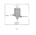
- Figure 2 of the present invention illustrates the typical diffusion flame burner, wherein carrier gas along with precursor or reactant is injected through the centre tube; fuel is injected through the second tube and oxidant through the third tube; wherein the diameter of centre tube, second tube and third tube are represented by d1, d2 and d3 respectively.
- the simulation tool with programmed instructions of the present invention determines the influence of the three burners with varying diameters of the central tube, the annulus and the outer tube, for scale-up of production of nanoparticles.
- the inner diameter of the central tube (d1) can be in the range 1.5-5.5 mm
- the inner diameter of the outer most tube (d3) can range from 5 mm to 25 mm
- the inner diameter of the tube in between the central and outer tubes (d2) could be in the range 3 mm - 12 mm.
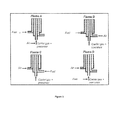
- Figure 3 of the present invention illustrates the typical aerosol flame burner configurations according to Johannssen et al., (2000).
- Flame A illustrates the injection of carrier gas along with precursor and air from the centre tube and fuel through the third tube, whereas no stream input is provided through the second tube.
- Flame B illustrates the injection of carrier gas along with precursor from the centre tube and air through the second tube while fuel through the third tube.
- Flame C illustrates the injection of carrier gas along with precursor from the centre tube and fuel through the second tube while air through the third tube.
- Flame D illustrates the injection of carrier gas along with precursor and fuel from the centre tube and air through the third tube, whereas no stream input is provided through the second tube.
- any of the four typical aerosol flame reactor burner configuration values and geometries as illustrated in figure 3 can be fed to the simulation tool with programmed instructions of the present invention to simulate, and determine the influence of the burner configuration and geometries on the particle size distribution in the aerosol flame reactor.
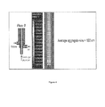
- Figure 4 shows the temperature contours and the value of the alumina aggregate particle size inside the flame reactor with burner configuration B (Flame B) of figure 3 , wherein methane in the input stream is fed to the burner through the third tube; air in the second tube and precursor and carrier gas in the first tube.
- the configuration of input streams (methane, air, carrier gas and precursor) to the burner has a strong influence on the flame characteristics and hence on the particle size.
- the influence of burner configuration and arrangement of the burner configurations on flame temperature profile is shown in Figure 4 .
- the flames in configuration B ( Figure 4 ) are shorter flames surrounded by air on both sides and hence, yield a more efficient combustion.
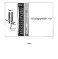
- Figure 5 shows the temperature contours and the value of the alumina aggregate particle size inside the flame reactor with burner configuration C (Flame C) of figure 3 , wherein methane in the input stream is fed to the burner through the second tube; air in the third tube and precursor and carrier gas in the first tube.
- the configuration of input streams to the burner has a strong influence on the flame characteristics and hence on the particle size.
- the influence of burner configuration on flame temperature profile is shown in Figure 5 .
- the configuration B (flame B) has methane in the third tube and air in the second tube where as configuration C has methane in the second tube and air in the third tube. This difference in arrangement alters the flame shape and size drastically as seen in the Figures 4 and 5 .
- Figure 6 illustrates the comparison of axial temperature profile in a laboratory scale flame reactor determined by simulation tool of the present invention with the experimental data of Johanessen et al ( T. Johannessen, S.E. Pratsinis and H. Livbjerg, Computational fluid-particle dynamics for the flame synthesis of alumina particles, Chemical Engineering Science, 55, 177-191 (2000 ))
- Figure 6 compares the data determined by the simulation tool with programmed instructions for the axial temperature profile and influence of distance above burner outlet (m) on the mean particle size with that of published experimental data of Johanessen et al (2000).
- Table 1 below provides and compares the simulated data determined by the simulation tool with programmed instructions for the axial temperature profile and influence of distance above burner outlet (m) on the mean particle size with that of published experimental data of Johanessen et al (2000).
- Table 1 Distance above burner outlet (m) Temperature (K) Experimental Simulated 0.00 500 500 0.01 1018 1091 0.02 1117 1493 0.03 1342 1672 0.04 1608 1764 0.05 1887 1816 0.06 1842 1796 0.07 1698 1572 0.08 1486 1462
- the data determinations made by the simulation tool of the present invention are relatively close to the experimental measurements and thereby indicating the accuracy of the data determinations made by the simulation tool of the present invention.
- Figure 7 illustrates the comparison of alumina aggregate particle sizes determined by simulation tool of the present invention with the experimental data of Johanessen et al ( T. Johannessen, S.E. Pratsinis and H. Livbjerg, Computational fluid-particle dynamics for the flame synthesis of alumina particles, Chemical Engineering Science, 55, 177-191 (2000 )). Further, Figure 7 compares the data determined by the simulation tool with programmed instructions for the various burner configurations and average particle size with that of published experimental data of Johanessen et al (2000).
- Table 2 below provides and compares the data determined and provided by simulation tool with programmed instructions i.e. simulated data for the various burner configurations and average particle size with that of published experimental data of Johanessen et al (2000).
- Table 2 Configuration Average particle size (nm) Experimental Simulated C1 179 193 C2 188 204 C3 223. 216 C4 176. 203 C5 187. 171 C6 196. 276 B1 115. 109 B2 146. 135 B3 180. 151 B4 106. 140 B5 132. 141 B6 174. 160
- the data determinations made by the tool of the present invention are relatively close to the experimental measurements and thereby indicating the accuracy of the data determined by the simulation tool of the present invention.
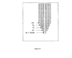
- Figure 8 illustrates the burner configuration with five concentric tubes for silica nanoparticles synthesis from Jang et al ( H.D. Jang, 2001, "Experimental study of synthesis of silica nanoparticles by a bench-scale diffusion flame reactor", Powder Technol., 119, 102-108 )
- Figure 8 shows that the simulation tool of the present invention was tested further for production of silica nanoparticles using a burner with five concentric tubes, wherein Ar and TEOS (precursor) was fed through the centre tube of the burner, Ar was fed through the second tube, H 2 was fed through the third tube, O 2 was fed through the fourth tube and air was fed through the fifth tube.
- Ar and TEOS precursor
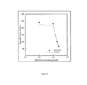
- Figure 9 illustrates the effect of TEOS (precursor) concentration on silica particle specific surface area and compares the data determined by the simulation tool of the present invention with the experimental data from Jang et al ( H.D. Jang, 2001, "Experimental study of synthesis of silica nanoparticles by a bench-scale diffusion flame reactor", Powder Technol., 119, 102-108 )
- the burner configuration of Figure 8 was integrated with the simulation tool of present invention, to determine the specific surface areas of silica particles at different precursor concentrations and compared with published experimental data from Jang et al (2001) in Figure 9 .
- Figure 9 illustrates the effect of TEOS (precursor) concentration on silica particle specific surface area and compares the data determined by the simulation tool of the present invention with the experimental data from Jang et al (2001). Further, Table 3 below provides and compares the effect of TEOS (precursor) concentration on silica particle specific surface area and the data determined and obtained by the simulation tool i.e. simulated data of the present invention with the experimental data from Jang et al (2009). Table 3: TEOS Concentration (l/min) Specific surface area (m 2 /g) Experimental Simulated 1.00E-05 240 225 1.00E-04 230 218 1.91E-04 101 94 2.50E-04 68 60
- the simulation tool with programmed instructions of the present invention was used to determine the influence of the three burners with varying diameters of the central tube, the annulus and the outer tube, for scale-up of production of nanoparticles.
- the inner diameter of the central tube (d1) can be in the range 1.5-5.5 mm
- the inner diameter of the outer most tube (d3) can range from 5 mm to 25 mm
- the inner diameter of the tube in between the central and outer tubes (d2) could be in the range 3 mm - 12 mm.
- the precursor and fuel flow rates were kept constant and the oxidant flow rate was varied in order to obtain the operating line of particle size versus fuel to oxidant velocity difference with different burner designs.
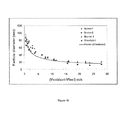
- Figure 10 illustrates Titanium dioxide particle diameter as a function of oxygen and fuel velocity difference with different burner designs and compares the data determined by the simulation tool of the present invention with the experimental data from Wegner and Pratsinis ( K. Wegner and S. E. Pratsinis, Scale-up of nanoparticle synthesis in diffusion flame reactors, Chemical Engineering Science, 58(20), 4581-4589 (2003 )).
- Figure 10 illustrates that particle size and specific surface area are key product characteristics during the scale-up of the nanoparticle production.
- the data determined by present invention tool for different burner designs that lead to different production rates were simulated.
- Table 4 provides and compares the data determined and obtained by the simulation tool i.e. simulated data for particle size and specific surface areas during the scale-up of the titania nanoparticle production of the present invention with the experimental data from Wegner and Pratsinis (2003).
- Burner Type Velocity difference ( ⁇ V-V oxidant - V fuel ) (m/s) Particle diameter (dp) (nm)
- Burner 1 71.9298 1.2366 70.9840 65.2047 2.9032 58.5689 57.3099 3.6559 45.5512 34.2105 7.6344 31.4976 23.9766 11.4516 25.6017 20.7602 15.5914 16.9228 20.1754 19.2473 13.7482 18.421 23.6559 11.7024 Burner 2 0.59140 78.3626 66.0397 1.6129 73.9766 53.7126 4.0860 47.6608 48.6079 6.3979 38.5965 40.1970 8.4409 31.2865 33.7597 10.7527 28.0702 25.4969 16.0215 23.09941 21.3075 22.2580 21.3450 17.9738 27.9570 20.4678 14.6581 Burner 3 0.48387 87.4269 77.6398 0.9
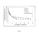
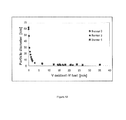
- Figure 11 illustrates Silica particle diameter as function of oxygen and fuel velocity difference with different burner designs and compares the data determined by the simulation tool of the present invention with the experimental data from Wegner and Pratsinis (K. Wegner and S. E. Pratsinis, Scale-up of nanoparticle synthesis in diffusion flame reactors, Chemical Engineering Science, 58(20), 4581-4589 (2003 )).
- Figure 11 illustrates that particle size and specific surface area are key product characteristics during the scale-up of the nanoparticle production.
- the data determined by present invention tool for different burner designs that lead to different production rates were simulated.
- Table 5 provides and compares the data determined and obtained by the simulation tool i.e. simulated data for particle size and specific surface areas during the scale-up of the silica nanoparticle production of the present invention with the experimental data from Wegner and Pratsinis (2003).
- Burner 1 1.8987 53.6873 53.3431 3.3635 42.7729 49.9199 6.4014 26.8437 42.9147 9.4394 19.7640 34.1374 12.4774 16.2242 29.8594 15.5154 15.0442 25.6395 18.5533 13.8643 21.4307 21.5913 13.5693 19.4750 24.5750 13.8643 17.8405 27.6130 12.9794 17.2361
- Burner 2 1.3020 61.6519 50.4210 3.0380 46.3127 44.4037 4.9367 30.3835 32.1954 6.7812 23.0088 29.4649 8.5714 17.9941 25.2198 10.4702 15.6342 21.6056
- Burner 3 0.2712 84.0708 66.4055 0.8137 71.9764 60.2579 1.3020 61.6519 52.0373 1.7902
- Figure 12 illustrates the influence of the different burner designs on the velocities of the oxidant and the fuel on carbon black particle size.
- Acetylene is used both as a precursor and as the fuel while oxygen was used as oxidant in this process. It is partially oxidized and upon using the heat liberated during oxidation, the remaining acetylene cracks into carbon black and hydrogen gas.
- Figure 12 The influence of the difference in the velocities of the oxidant and the fuel on carbon black particle size is shown in Figure 12 .
- Table 6 provides the data obtained by the simulation tool i.e. simulated data for determining the influence of the difference in the velocities of the oxidant and the fuel on carbon black particle size
- Burner 1 1.8987 53.6873 3.3635 42.7729 6.4014 26.8437 9.4394 19.7640 12.4774 16.2242 15.5154 15.0442 18.5533 13.8643 21.5913 13.5693 24.5750 13.8643 27.6130 12.9794
- Burner 2 1.3020 61.6519 3.0380 46.3127 4.9367 30.3835 6.7812 23.0088 8.5714 17.9941 10.4702 15.6342
- Burner 3 0.2712 84.0708 0.8137 71.9764 1.3020 61.6519 1.7902 57.5221 2.2242 51.6224
- results indicate the validity of the simulation tool of the present invention for determining the operating line of particle size versus difference in velocities of the oxidant and the fuel.
- the simulation tool of the present invention can be utilized for detailed process design and process optimization to produce nanoparticles at different levels of production.
Landscapes
- Chemical & Material Sciences (AREA)
- Organic Chemistry (AREA)
- Inorganic Chemistry (AREA)
- Engineering & Computer Science (AREA)
- Geology (AREA)
- General Life Sciences & Earth Sciences (AREA)
- Environmental & Geological Engineering (AREA)
- Life Sciences & Earth Sciences (AREA)
- Nanotechnology (AREA)
- Crystallography & Structural Chemistry (AREA)
- Materials Engineering (AREA)
- General Physics & Mathematics (AREA)
- Physics & Mathematics (AREA)
- Condensed Matter Physics & Semiconductors (AREA)
- Composite Materials (AREA)
- Automation & Control Theory (AREA)
- Chemical Kinetics & Catalysis (AREA)
- Oxygen, Ozone, And Oxides In General (AREA)
- Physical Or Chemical Processes And Apparatus (AREA)
Abstract
Description
- The present invention relates to a system and a method for optimizing and controlling the particle size distribution and for scale-up of production of nanoparticles in an aerosol flame reactor. More particularly the present invention relates to a system and a method for optimization of mean particle size, specific surface area, and distribution of nanoparticles in aerosol reactors.
- In the recent years, nanotechnology has gained importance and has become one of the major research focus areas for its fundamental and practical applications. The smaller size of the particles especially less than 100 nm is one of the key parameters that is responsible for various properties such as electronic, electric, optical, magnetic chemical and mechanical properties that makes nanoparticles suitable for several applications in the fields of ceramics, catalysis, coatings, electronics, chemical and mechanical polishing, data storage, fuel cells, etc.
- Many commodity and specialty chemicals and materials such as carbon black, titania, silica and zinc oxide are produced in the form of fine particles, which find applications in a wide variety of industrial and domestic products ranging from tyres, printing inks, paints and pigments, plastics, optical fibers, catalysts, pharmaceutical ingredients and cosmetics.
- For many practical applications, it is desirable to have particles of small size as well as of narrow size distribution because smaller particles with narrow size distribution result in better properties of finished products. For example, activity of catalysts, hardness and strength of metals, electrical conductivity of ceramics improve as the particle size decreases.
- These special properties of the nanoparticles can vary markedly from those of the analogous bulk materials. The physical and chemical properties of the nanomaterials tend to be exceptionally dependent on their size and shape or morphology. As a result, materials scientists are focusing their efforts on developing simple and effective methods for producing nanomaterials with controlled particle size and morphology and hence, improving their properties.
- Many techniques and methods have been employed for the synthesis of nanoparticles on the laboratory scale. Some of the well known methods and systems are as follows:
- a) Gas phase synthesis process: It is one of the routinely employed techniques used for large scale production of nano powders, as it is a single step process without any moving parts and any extensive solid-liquid separation processes.
- b) Chemical and mechanical routes such as microemulsion-based synthesis and grinding.
- Amongst the above mentioned methods and techniques, flame aerosol synthesis is one of the commonly and widely used technologies for synthesis of fine powders on an industrial scale, as it offers many control parameters like flame temperature, flame structure, stoichiometry, pressure level, residence time distribution, turbulence etc.
- The typical method of synthesis of nanoparticles in flame aerosol synthesis is as follows:
- a) Injecting the precursor or reactant into the reactor in the form of a vapor or liquid using a carrier gas along with air and fuel.
- b) Chemical reactions occur in the gas phase in the flame at high temperatures and results in product molecules;
- c) Growth of the particles by coagulation and/or surface reaction to form product particles due to decrease in the temperature at downstream in the reactor
- The temperature decrease at the downstream of the reactor results in the particle growth mainly by coagulation and results in irregularly structured particles and particle distribution.
- Further, the powders produced in the aerosol flame reactors have a relatively large particle size and have wide size distribution, with particle size ranging from a few nanometers to micrometers, the said wide particle size distribution is influenced by several factors, namely, burner geometry, nature of flame and its configuration, inlet reactant flow rate and its concentration, and turbulence characteristics, gas and particle velocities, pressure and temperature profiles and residence time distribution inside the reactor.
- Yet another challenging task lies in scaling up of the process to produce nanoparticles in large quantities, while at the same time maintaining the particle size in the nanometer range.
- Hence, there is a need for controlling the product particle size distribution by manipulating and designing the process input variables.
- Further, there is also a need for scaling up the process of synthesis of nanoparticles with desired characteristics.
- Some of the prior arts that propose a system, method and scale-up process for synthesis of nano-particles are as follows:
-
US 5498446 (Axelbaum et al ) teaches a method and apparatus for reacting sodium vapor with gaseous chlorides in a flame to produce nanoscale particles of un-oxidized metals, composites and ceramics. The flame is operated under conditions which lead to condensation of a NaCl byproduct onto the particles. The condensate encapsulates the particles and aids in controlling desired particle size and preventing undesirable agglomeration among the particles during synthesis. Following synthesis, oxidation of the particles is inhibited by the encapsulation and handling character of the products is greatly enhanced. Though the '446 patent discloses a method and apparatus for synthesis of nanoparticles, it does not disclose the means for optimization, and controlled particle size distribution of nanoparticles. Further, '446 patent does not address challenging aspect for the scale-up of production of nanoparticles with the desired particle size. -
EP 1122212 (Hendrik et al ) teaches a method to control particle characteristics of flame made nanostructured powders and investigated at high production rates addressing the required safety concerns. The influence of increasing the fuel and production rate, burner configuration and total oxidant flow on particle size morphology and composition is presented for synthesis of silica in a commercial oxy-hydrogen burner. Hence, the said patent application discloses a method to control particle characteristics of flame made nanostructured powders experimentally, which is expensive and time consuming. - "Computational fluid-particle dynamics for the flame synthesis of alumina particles" by Johannessen et al (2000) discloses a mathematical model for the dynamics of particle growth during the synthesis of the ultra fine particles in diffusion flame. The said article combines a simple batch model for coagulation and coalescence of aerosol particles along with the computational fluid dynamics model (Fluent) in a decoupled manner to simulate the gas composition, temperature and velocity profiles in a flame reactor and integrate the simple monodisperse population balance (MPB) model along a set of "characteristic trajectories" only and not for the entire flame structure. Further, the said article discloses the computational fluid-particle dynamics for the flame synthesis using specific burner with three concentric quartz tubes. Further, the said article does not determine the particle characteristics throughout the reactor and does not determine the particle characteristics using various burners and does not address the challenging aspect for the scale-up of production of nanoparticles with the desired particle size. Further, the simple kinetics used in the article only applies for a limited range of temperature and particle size.
- Thus, in light of the above mentioned prior arts it is evident that there is a need to have a customizable solution for optimizing and controlling the particle size distribution in a continuous process rather than a batch process and scale-up of production of nanoparticle in an aerosol flame reactor.
- Further, there is a need to have a customizable solution to optimize and control the particle size distribution and scale-up of production of nanoparticles in aerosol flame reactor in a coupled manner i.e. by solving the particle dynamics equations in each and every cell of the computational domain.
- It is also evident that the process equipment design and scale-up, pilot scale studies are tedious and expensive. Hence, there is growing demand to have a customizable solution for synthesis and scale-up of nanoparticles with desired particle size and shape by improving the process design and scale-up which provides the basic process understanding and dynamic behavior of the flame reactor to reduce the efforts on pilot plant studies for the synthesis of any material.
- In the present invention we propose a novel approach for optimizing and controlling the particle size distribution and scale-up of production of nanoparticles in aerosol flame reactor to overcome the above mentioned limitations for synthesis of nanoparticles with controlled particle size, shape and particle size distribution.
- In order to address the long felt need for such a solution, the present invention provides a system and method for optimizing and controlling the particle size and scale-up of production of nanoparticles in an aerosol flame reactor, described more particularly herein after.
- The principle object of the invention is to provide a system and method for optimizing and controlling the particle size and specific surface area of nanoparticles in an aerosol flame reactor.
- Another object of the invention is to provide a system and method for scaling up the synthesis of nanoparticles in an aerosol flame reactor.
- Another object of the invention is to provide cost effective system and method for optimizing and controlling the particle size and specific surface area of nanoparticles in an aerosol flame reactor.
- Another object of the invention is to provide cost effective method for scaling up synthesis of nanoparticles in an aerosol flame reactor.
- Another object of the invention is to provide system and method which optimizes and controls the particle size and specific surface area of nanoparticles in an aerosol flame reactor requiring less experimentation and utilizing less time.
- Another object of the invention is to provide a method for scaling up synthesis of nanoparticles in an aerosol flame reactor which requires less experimentation.
- Yet another object of the invention is to provide a simulation tool with programmed instructions for production of nanoparticles with controlled properties.
- The present invention discloses a system and method for optimizing and controlling mean particle size and specific surface area and for scale-up of nanoparticle production in an aerosol flame reactor.
- A system for optimizing and controlling mean particle size and specific surface area and for scale-up of nanoparticle production in aerosol flame reactor comprising of:
- an aerosol flame reactor integrated with process instruments, wherein the said reactor further comprises of
- at least one burner;
- at least one precursor or reactant fed to the said aerosol flame reactor;
- at least one stream input fed along with at least one precursor or reactant to the said aerosol flame reactor;
- a simulation tool with programmed instructions to cause the processor to couple flame dynamics model and particle population balance model in order to optimize and control mean particle size and specific surface area and for scale-up of nanoparticle production in aerosol flame reactor.
- A method for optimizing and controlling the mean particle size and specific surface area and for scale up of nanoparticle production in an aerosol flame reactor integrated with the process instruments, wherein the said method comprises the steps of:
- a) Determining
- i) the operating data for physical process parameters from the said process instruments integrated with aerosol flame reactor;
- ii) the mixing characteristics of the precursor or reactant at a particular concentration and the stream input fed to the burner of the said aerosol flame reactor with the process instruments;
- iii) the flame temperature and different species mass-fractions throughout the said reactor using the Flame dynamics model coupled to the simulation tool with programmed instructions;
- iv) the data for influence of burner configuration and the design of the reactor on the properties of nanoparticles.
- b) Feeding the determined data of step i) to the simulation tool with the programmed instructions to obtain the simulated data for optimizing and controlling the mean particle size and specific surface area and for scale up of nanoparticle production in an aerosol flame reactor integrated with the process instruments;
- c) Implementation of the simulated data obtained from the said simulation tool with programmed instructions for optimizing and controlling the mean particle size and specific surface area and for scale up of nanoparticle production in an aerosol flame reactor integrated with the process instruments;
- d) Estimating the rate kinetics of the precursor oxidation reaction using the precursor to product conversion kinetics coupled to Particle population balance model of the said simulation tool with programmed instructions;
- e) Obtaining the output as product particle size and specific surface area of the reactor from the simulation tool with the programmed instructions to optimize and control the particle size distribution and for scale up of nanoparticle production in an aerosol flame reactor integrated with the process instruments.
- The foregoing summary, as well as the following detailed description of preferred embodiments, is better understood when read in conjunction with the appended drawings. For the purpose of illustrating the invention, there is shown in the drawings, exemplary constructions of the invention; however, the invention is not limited to the specific methods disclosed. In the drawings:
-
Figure 1 of the present invention illustrates the structure of the simulation tool with programmed instructions. -
Figure 2 illustrates the typical diffusion flame burner. -
Figure 3 illustrates the typical aerosol flame burner configurations (Source of figure: T. Johannessen, S.E. Pratsinis and H. Livbjerg, Computational fluid-particle dynamics for the flame synthesis of alumina particles, Chemical Engineering Science, 55, 177-191 (2000)). -
Figure 4 illustrates the temperature contours and the value of the alumina aggregate particle size inside the flame reactor with burner configuration B (Source for Flame B figure: T. Johannessen, S.E. Pratsinis and H. Livbjerg, Computational fluid-particle dynamics for the flame synthesis of alumina particles, Chemical Engineering Science, 55, 177-191 (2000)). -
Figure 5 illustrates the temperature contours and the value of the alumina aggregate particle size inside the flame reactor with burner configuration C (Source for Flame C figure: T. Johannessen, S.E. Pratsinis and H. Livbjerg, Computational fluid-particle dynamics for the flame synthesis of alumina particles. Chemical Engineering Science, 55, 177-191 (2000)). -
Figure 6 illustrates the comparison of axial temperature profile in a laboratory scale flame reactor determined by simulation tool of the present invention with the experimental data of Johanessen et al (T. Johannessen, S.E. Pratsinis and H. Livbjerg, Computational fluid-particle dynamics for the flame synthesis of alumina particles, Chemical Engineering Science, 55, 177-191 (2000)) -
Figure 7 illustrates the comparison of alumina aggregate particle sizes determined by simulation tool of the present invention with the experimental data of Johanessen et al (T. Johannessen, S.E. Pratsinis and H. Livbjerg, Computational fluid-particle dynamics for the flame synthesis of alumina particles, Chemical Engineering Science, 55, 177-191 (2000)) -
Figure 8 illustrates the burner configuration with five concentric tubes for silica nanoparticles synthesis from Jang et al (H.D. Jang, 2001, "Experimental study of synthesis of silica nanoparticles by a bench-scale diffusion flame reactor", Powder Technol., 919, 102-108) -
Figure 9 illustrates the effect of TEOS (precursor) concentration on silica particle specific surface area and compares the data determined by the simulation tool of the present invention with the experimental data from Jang et al (H.D. Jang, 2001, "Experimental study of synthesis of silica nanoparticles by a bench-scale diffusion flame reactor", Powder Technol., 119, 102-108) -
Figure 10 illustrates Titanium dioxide particle diameter as a function of oxygen and fuel velocity difference with different burner designs and compares the data determined by the simulation tool of the present invention with the experimental data from Wegner and Pratsinis (K. Wegner and S. E. Pratsinis, Scale-up of nanoparticle synthesis in diffusion flame reactors, Chemical Engineering Science, 58(20), 4581-4589 (2003)). -
Figure 11 illustrates Silica particle diameter as function of oxygen and fuel velocity difference with different burner designs and compares the data determined by the simulation tool of the present invention with the experimental data from Wegner and Pratsinis (K. Wegner and S. E. Pratsinis, Scale-up of nanoparticle synthesis in diffusion flame reactors, Chemical Engineering Science, 58(20), 4581-4589 (2003)). -
Figure 12 illustrates the influence of the different burner designs on the velocities of the oxidant and the fuel on carbon black particle size. - Before the present method, and hardware enablement are described, it is to be understood that this invention in not limited to the particular methodologies, and hardware described, as these may vary. It is also to be understood that the terminology used in the description is for the purpose of describing the particular versions or embodiments only, and is not intended to limit the scope of the present invention which will be limited only by the appended claims. The words "comprising," "having," "containing," and "including," and other forms thereof, are intended to be equivalent in meaning and be open ended in that an item or items following any one of these words is not meant to be an exhaustive listing of such item or items, or meant to be limited to only the listed item or items. The disclosed embodiments are exemplary to the invention, which may be embodied in various forms.
- The present invention provides a system for optimizing and controlling particle size distribution and for scale-up of nanoparticle production in an aerosol flame reactor comprising of:
- an aerosol flame reactor integrated with process instruments, wherein the said reactor further comprises of
- at least one burner;
- at least one precursor or reactant fed to the said aerosol flame reactor;
- at least one stream input fed along with at least one precursor or reactant to the said aerosol flame reactor;
- a simulation tool with programmed instructions to cause the processor to couple flame dynamics model and particle population balance model in order to optimize and control mean particle size and specific surface area and for scale-up of nanoparticle production in an aerosol flame reactor.
- According to one of the embodiments of the present invention, the process instruments comprises of precursor flow rate gauze, precursor pressure gauze, air flow rate gauze, air pressure gauze, fuel flow rate gauze, fuel pressure gauze, carrier gas flow rate gauze, carrier gas pressure gauze and temperature sensors.
- The process instruments integrated with the aerosol flame reactor provides the operating data for variables such as precursor flow rate, precursor pressure, air flow rate, air pressure, carrier gas flow rate, carrier gas pressure to the simulation tool with programmed instructions to manage the process.
-
Figure 1 of the present invention illustrates the structure of the simulation tool with programmed instructions. - According to one of the embodiments of the present invention, simulation tool with programmed instructions (10) couples flame dynamics model (20) and particle population balance model (30) to optimize and control the mean particle size and specific surface area and for scale-up of the production of nanoparticles with the desired characteristics.
- Flame dynamics model (20) coupled to the simulation tool with programmed instructions determines the flame temperature and different species mass-fractions throughout the reactor and further determines and simulates the physical process parameters such as but not limited to fluid flow rate, heat transfer rate, etc.
- Further, the Flame dynamics model (20) is coupled with fuel combustion kinetics (70) for managing operating data obtained from the various process instruments of the aerosol flame reactor.
- The governing equations for the flame dynamics model are as follows:
- The equation of motion according to Bird et al., (2002)

Wherein ρ is gas density (kg/m3), u is velocity (m/s), τ (t) is turbulent momentum flux tensor (kg/s2/m), τ is stress tensor (kg/s2/m) and g is gravitational acceleration (m/s2). - Further, as per Launder and Spalding (1974), the k-ε model is used for calculating the turbulent kinetic energy, k (m2/s2) and its dissipation rate, ε (m2/s3)


where Pk is turbulence production due to viscous and buoyancy forces (kg/s3) which is obtained using the following equation:
where µ t is turbulent viscosity (kg/m/s) given by
- The continuity equation for component i as given by (CFX 11.0 User's Manual):

- The equation of energy in terms of the specific enthalpy h (J/kg) is given by (CFX 11.0 User's Manual):

where kg is thermal conductivity of the gas (J/m/s/K), SE is source term that denotes the rate of heat liberated due to chemical reaction and heat absorption due to radiation. τ : ∇u is always negative and is called the viscous dissipation. - The P-1 radiation model according to Siegel and Howell (1992) is incorporated in the enthalpy balance to account for radiant energy absorption and irradiation. The radiation flux is expressed by expanding the radiation intensity in series of orthogonal harmonics in this model. The radiation flux is then directly incorporated into the enthalpy balance to account for the radiation heat transfer process.
- The rate of fuel combustion is calculated using the eddy-dissipation model (EDM) proposed by Magnussen and Hjertager (1976). The chemical reaction is fast relative to the transport processes. The fuel combustion model consists of two rate expressions, Equations 7 and 8 given below. Equation 7 represents the reaction rate R1 (kmol/m3/s) that accounts for the mixing of the reactants in the turbulent eddies.

where [I] (kmol/m3) is concentration of the reactant I, v1 is the stoichiometric coefficient of component I and AEDM is a numerical constant. - Equation 8 represents the reaction rate R2 (kmol/m3/s) that accounts for the mixing of the hot product gases with the cold reactant gases when heat transport to the unreacted gases is the limiting factor.

- P loops over all product components in the reaction. In Eq.8, W1 (kg/kgmol) is molar mass of the component I and BEDM is a numerical constant. The rate of combustion is determined by the smaller of the two rates R1 and R2 .
- Particle population balance model (30) coupled to the simulation tool with programmed instructions determines the properties of evolved particles.
- The governing equations for particle population balance model (30) are as follows:
- The rate of change of particle number concentration (N) is given by:

where η (m2/sec) is diffusion coefficient, β (m3/sec) is coagulation rate coefficient and I (#/m3-sec) is rate of nucleation (Ji et al.,2007):
where kn (#.s-1.m3) is nucleation rate constant, S is degree of supersaturation and the exponent Nn is taken as 1. The last term on the RHS of Eq. 9 represents the reduction of particle number concentration N by coagulation. The coagulation rate coefficient β is calculated using the Fuchs equation (Fuchs,1964; Seinfield, 1986).
- The particle diffusion coefficient D is calculated as given by Johannessen (1999):

where Kn is the Knudsen number (λ/rc ), λ (m) is the gas mean free path and µ (Pa.s) is viscosity of the gas. The total surface area density of the particles A (m2/m3) decreases by coalescence but remains unaffected by coagulation.
where ap is the monomer surface area (m2), τ f is characteristic coalescence time (s) and Amin is minimal total surface area density, given by:
where V is total particle volume density (m3/m3). The characteristic coalescence time τ f depends on temperature, primary particle size, material, sintering mechanism, etc. Particle coalescence occurs due to a combination of mechanisms, namely, surface diffusion, grain boundary diffusion, solid state diffusion and viscous flow. - The characteristic coalescence time τ f of two separate, contacting spherical particles is given by Johannesssen et al. (2000):

where EA is activation energy, dp is initial diameter of the two primary contacting spherical particles in an aggregate, k0 is pre-exponential term, T0 is temperature and R is universal gas constant. - The total particle volume density V (m3/m3) increases by nucleation and chemical reaction.

where vp is the monomer volume (m3) and Sv is rate of increase of total particle mass per unit volume of the system (kg/m3.s), given by the following equation:
where G is total growth rate of a particle (m/s). The total growth rate G under the combined control of chemical reaction and mass transfer is calculated as
where GM is growth rate of a particle under the control of mass transfer (m/s) and Gc is growth rate of a particle under the control of chemical reaction kinetics (m/s). The linear growth rate of a particle under the control of mass transfer GM (m/s) is given by:
where Vmol is molar volume of the product molecule produced (m3/mol): TiO2, SiO2 or Carbon black, DA - O2 is diffusion coefficient of A (product molecule) through O2 (m2/s), S is degree of supersaturation, dn is number-averaged particle size (m),

where kgc is particle growth rate constant (m/s). The exponent Ng is assumed to be 1. When S ≤1, G c is set equal to zero. - Particle population balance model (30) determines the properties of the evolved particles on the basis of the above discussed equations for particle number concentration, particle volume and particle surface area.
- Particle population balance model (30) is further coupled to precursor to product conversion kinetics (80) for monitoring and controlling the particle size distribution of nanoparticles and further estimates the rate kinetics of the precursor oxidation reaction.
- The combined eddy dissipation - finite rate chemistry model available in CFX 11.0 represents the oxidation of precursor to product molecules. The rate of oxidation is taken as the minimum of the rates obtained using the Arrhenius expression, given below, and the eddy dissipation model (Eqs. 7 and 8).

where A is pre-exponential factor, E (J/kmol-K) is activation energy, Cprecursor (kmol/m3) is the concentration of the precursor, CO2 (kmol/m3) is concentration of oxygen and R (J.kmol-1.K-1) is the universal gas constant. - In one of the embodiments of the present invention, the simulation tool with programmed instructions is developed on a FORTRAN platform to simulate and determine the physical processes.
- Nanoparticles with desired particle size and shape are produced in the aerosol flame reactors on provision of the various optimized operating conditions (40) such as but not limited to flame temperature, pressure, optimum gas flow rate, and reactant or precursor concentrations.
- The values for various optimized operating conditions are provided to the simulation tool with the programmed instructions so as to simulate and determine the influence of these various operating parameters on the particle size and specific surface area of the nanoparticles.
- Further, according to another embodiment of the present invention, the geometry and design (50) of the reactor and burner also influences the particle size, particle size distribution and shape of the nanoparticles. The various sizes of burners, the number of concentric tubes of the burner, the spacing between each tube, diameter of the tubes of the burner are fed to the simulation tool with the programmed instructions so as to simulate and determine the influence of the variable geometry and design of the burner and reactor on the particle size.
- Further according to one of the embodiments of the present invention, the burners are designed and configured for various stream inputs to the aerosol flame reactor.
- Further according to one of the embodiments of the present invention the burner geometry is designed and implemented in co-ordination with the simulation tool with programmed instructions in terms of number of concentric tubes, diameters of each tube and spacing between each tube.
- According to another embodiment of the present invention the various characteristics and properties of the physical constants and materials (60) are fed to the simulation tool with the programmed instructions so as to simulate and determine the influence of the characteristics and properties of the materials (60) on the particle size distribution.
- The simulation tool with the programmed instructions provides output (90) as product particle size and specific surface area of the reactor.
-
Figure 2 of the present invention illustrates the typical diffusion flame burner, wherein carrier gas along with precursor or reactant is injected through the centre tube; fuel is injected through the second tube and oxidant through the third tube; wherein the diameter of centre tube, second tube and third tube are represented by d1, d2 and d3 respectively. - According to one of the embodiments of the present invention, the simulation tool with programmed instructions of the present invention determines the influence of the three burners with varying diameters of the central tube, the annulus and the outer tube, for scale-up of production of nanoparticles. The inner diameter of the central tube (d1) can be in the range 1.5-5.5 mm, the inner diameter of the outer most tube (d3) can range from 5 mm to 25 mm while the inner diameter of the tube in between the central and outer tubes (d2) could be in the
range 3 mm - 12 mm. -
Figure 3 of the present invention illustrates the typical aerosol flame burner configurations according to Johannssen et al., (2000). - According to one of the embodiments, four typical aerosol flame reactor burner configurations are illustrated in
Figure 3 with respect to the various modes of stream inputs. - Flame A illustrates the injection of carrier gas along with precursor and air from the centre tube and fuel through the third tube, whereas no stream input is provided through the second tube.
- Flame B illustrates the injection of carrier gas along with precursor from the centre tube and air through the second tube while fuel through the third tube.
- Flame C illustrates the injection of carrier gas along with precursor from the centre tube and fuel through the second tube while air through the third tube.
- Flame D illustrates the injection of carrier gas along with precursor and fuel from the centre tube and air through the third tube, whereas no stream input is provided through the second tube.
- Any of the four typical aerosol flame reactor burner configuration values and geometries as illustrated in
figure 3 can be fed to the simulation tool with programmed instructions of the present invention to simulate, and determine the influence of the burner configuration and geometries on the particle size distribution in the aerosol flame reactor. - The invention is described in the examples given below which is provided only to illustrate the invention and therefore should not be construed to limit the scope of the invention.
-
Figure 4 shows the temperature contours and the value of the alumina aggregate particle size inside the flame reactor with burner configuration B (Flame B) offigure 3 , wherein methane in the input stream is fed to the burner through the third tube; air in the second tube and precursor and carrier gas in the first tube. - The configuration of input streams (methane, air, carrier gas and precursor) to the burner has a strong influence on the flame characteristics and hence on the particle size. The influence of burner configuration and arrangement of the burner configurations on flame temperature profile is shown in
Figure 4 . - The flames in configuration B (
Figure 4 ) are shorter flames surrounded by air on both sides and hence, yield a more efficient combustion. -
Figure 5 shows the temperature contours and the value of the alumina aggregate particle size inside the flame reactor with burner configuration C (Flame C) offigure 3 , wherein methane in the input stream is fed to the burner through the second tube; air in the third tube and precursor and carrier gas in the first tube. - The configuration of input streams to the burner has a strong influence on the flame characteristics and hence on the particle size. The influence of burner configuration on flame temperature profile is shown in
Figure 5 . - The configuration B (flame B) has methane in the third tube and air in the second tube where as configuration C has methane in the second tube and air in the third tube. This difference in arrangement alters the flame shape and size drastically as seen in the
Figures 4 and5 . - The flames in configuration B (
Figure 4 ) are surrounded by air on both sides and hence, yield a more efficient combustion than those in configuration C. - For this reason, flames in configuration B are shorter than those in configuration C (
Figure 5 ), with slightly higher temperatures than the latter. -
Figure 6 illustrates the comparison of axial temperature profile in a laboratory scale flame reactor determined by simulation tool of the present invention with the experimental data of Johanessen et al (T. Johannessen, S.E. Pratsinis and H. Livbjerg, Computational fluid-particle dynamics for the flame synthesis of alumina particles, Chemical Engineering Science, 55, 177-191 (2000)) -
Figure 6 compares the data determined by the simulation tool with programmed instructions for the axial temperature profile and influence of distance above burner outlet (m) on the mean particle size with that of published experimental data of Johanessen et al (2000). - Further, Table 1 below provides and compares the simulated data determined by the simulation tool with programmed instructions for the axial temperature profile and influence of distance above burner outlet (m) on the mean particle size with that of published experimental data of Johanessen et al (2000).
Table 1: Distance above
burner outlet (m)Temperature (K) Experimental Simulated 0.00 500 500 0.01 1018 1091 0.02 1117 1493 0.03 1342 1672 0.04 1608 1764 0.05 1887 1816 0.06 1842 1796 0.07 1698 1572 0.08 1486 1462 - It can be noticed that the data determinations made by the simulation tool of the present invention are relatively close to the experimental measurements and thereby indicating the accuracy of the data determinations made by the simulation tool of the present invention.
-
Figure 7 illustrates the comparison of alumina aggregate particle sizes determined by simulation tool of the present invention with the experimental data of Johanessen et al (T. Johannessen, S.E. Pratsinis and H. Livbjerg, Computational fluid-particle dynamics for the flame synthesis of alumina particles, Chemical Engineering Science, 55, 177-191 (2000)). Further,Figure 7 compares the data determined by the simulation tool with programmed instructions for the various burner configurations and average particle size with that of published experimental data of Johanessen et al (2000). - Further, Table 2 below provides and compares the data determined and provided by simulation tool with programmed instructions i.e. simulated data for the various burner configurations and average particle size with that of published experimental data of Johanessen et al (2000).
Table 2: Configuration Average particle size (nm) Experimental Simulated C1 179 193 C2 188 204 C3 223. 216 C4 176. 203 C5 187. 171 C6 196. 276 B1 115. 109 B2 146. 135 B3 180. 151 B4 106. 140 B5 132. 141 B6 174. 160 - It can be noticed that the data determinations made by the tool of the present invention are relatively close to the experimental measurements and thereby indicating the accuracy of the data determined by the simulation tool of the present invention.
-
Figure 8 illustrates the burner configuration with five concentric tubes for silica nanoparticles synthesis from Jang et al (H.D. Jang, 2001, "Experimental study of synthesis of silica nanoparticles by a bench-scale diffusion flame reactor", Powder Technol., 119, 102-108) -
Figure 8 shows that the simulation tool of the present invention was tested further for production of silica nanoparticles using a burner with five concentric tubes, wherein Ar and TEOS (precursor) was fed through the centre tube of the burner, Ar was fed through the second tube, H2 was fed through the third tube, O2 was fed through the fourth tube and air was fed through the fifth tube. -
Figure 9 illustrates the effect of TEOS (precursor) concentration on silica particle specific surface area and compares the data determined by the simulation tool of the present invention with the experimental data from Jang et al (H.D. Jang, 2001, "Experimental study of synthesis of silica nanoparticles by a bench-scale diffusion flame reactor", Powder Technol., 119, 102-108) - The burner configuration of
Figure 8 was integrated with the simulation tool of present invention, to determine the specific surface areas of silica particles at different precursor concentrations and compared with published experimental data from Jang et al (2001) inFigure 9 . -
Figure 9 illustrates the effect of TEOS (precursor) concentration on silica particle specific surface area and compares the data determined by the simulation tool of the present invention with the experimental data from Jang et al (2001). Further, Table 3 below provides and compares the effect of TEOS (precursor) concentration on silica particle specific surface area and the data determined and obtained by the simulation tool i.e. simulated data of the present invention with the experimental data from Jang et al (2009).Table 3: TEOS Concentration
(l/min)Specific surface area (m2/g) Experimental Simulated 1.00E-05 240 225 1.00E-04 230 218 1.91E-04 101 94 2.50E-04 68 60 - It can be observed that the trend determined by the simulation tool of the present invention is in close agreement with the experimental measurements, further indicating the accuracy of the data determined by the simulation tool of the present invention.
- Further, the simulation tool with programmed instructions of the present invention was used to determine the influence of the three burners with varying diameters of the central tube, the annulus and the outer tube, for scale-up of production of nanoparticles. The inner diameter of the central tube (d1) can be in the range 1.5-5.5 mm, the inner diameter of the outer most tube (d3) can range from 5 mm to 25 mm while the inner diameter of the tube in between the central and outer tubes (d2) could be in the
range 3 mm - 12 mm. - The precursor and fuel flow rates were kept constant and the oxidant flow rate was varied in order to obtain the operating line of particle size versus fuel to oxidant velocity difference with different burner designs.
- Few key examples are demonstrated here for the synthesis of titanium dioxide, silica and carbon black. The data determined by the simulation tool of the present invention are compared with published experimental data for validation of the methodology developed in the present invention.
-
Figure 10 illustrates Titanium dioxide particle diameter as a function of oxygen and fuel velocity difference with different burner designs and compares the data determined by the simulation tool of the present invention with the experimental data from Wegner and Pratsinis (K. Wegner and S. E. Pratsinis, Scale-up of nanoparticle synthesis in diffusion flame reactors, Chemical Engineering Science, 58(20), 4581-4589 (2003)). - According to one of the exemplary embodiments of the invention,
Figure 10 illustrates that particle size and specific surface area are key product characteristics during the scale-up of the nanoparticle production. In order to verify and validate the simulation tool of the present invention, the data determined by present invention tool for different burner designs that lead to different production rates were simulated. - These simulation results are compared with published experimental data from Wegner and Pratsinis (2003) in
figure 10 for scale-up of Titania production. - Further, Table 4 below provides and compares the data determined and obtained by the simulation tool i.e. simulated data for particle size and specific surface areas during the scale-up of the titania nanoparticle production of the present invention with the experimental data from Wegner and Pratsinis (2003).
Table 4: Burner Type Velocity difference (ΔV-Voxidant - Vfuel) (m/s) Particle diameter (dp)
(nm)Experimental Simulated Burner 1 71.9298 1.2366 70.9840 65.2047 2.9032 58.5689 57.3099 3.6559 45.5512 34.2105 7.6344 31.4976 23.9766 11.4516 25.6017 20.7602 15.5914 16.9228 20.1754 19.2473 13.7482 18.421 23.6559 11.7024 Burner 2 0.59140 78.3626 66.0397 1.6129 73.9766 53.7126 4.0860 47.6608 48.6079 6.3979 38.5965 40.1970 8.4409 31.2865 33.7597 10.7527 28.0702 25.4969 16.0215 23.09941 21.3075 22.2580 21.3450 17.9738 27.9570 20.4678 14.6581 Burner 30.48387 87.4269 77.6398 0.9140 82.4561 66.0369 1.2903 77.7778 61.6103 1.8280 78.3626 55.5556 2.2580 61.4035 51.0270 - It can be observed that the trend determined by the simulation tool of the present invention in scale-up trials for titania particle production is in close agreement with the experimental measurements for scale-up trials of K. Wegner and S. E. Pratsinis, further indicating the accuracy of the data determined by the simulation tool of the present invention.
-
Figure 11 illustrates Silica particle diameter as function of oxygen and fuel velocity difference with different burner designs and compares the data determined by the simulation tool of the present invention with the experimental data from Wegner and Pratsinis (K. Wegner and S. E. Pratsinis, Scale-up of nanoparticle synthesis in diffusion flame reactors, Chemical Engineering Science, 58(20), 4581-4589 (2003)). - According to one of the exemplary embodiments of the invention,
Figure 11 illustrates that particle size and specific surface area are key product characteristics during the scale-up of the nanoparticle production. In order to verify and validate the simulation tool of the present invention, the data determined by present invention tool for different burner designs that lead to different production rates were simulated. - These simulation results are compared with published experimental data from Wegner and Pratsinis (2003) in
figure 11 for scale-up of Silica particle production. - Further, Table 5 below provides and compares the data determined and obtained by the simulation tool i.e. simulated data for particle size and specific surface areas during the scale-up of the silica nanoparticle production of the present invention with the experimental data from Wegner and Pratsinis (2003).
Table 5: Burner Type Velocity difference (ΔV=Voxidant - Vfuel) (m/s) Particle diameter (dp) (nm) Experimental Simulated Burner 1 1.8987 53.6873 53.3431 3.3635 42.7729 49.9199 6.4014 26.8437 42.9147 9.4394 19.7640 34.1374 12.4774 16.2242 29.8594 15.5154 15.0442 25.6395 18.5533 13.8643 21.4307 21.5913 13.5693 19.4750 24.5750 13.8643 17.8405 27.6130 12.9794 17.2361 Burner 2 1.3020 61.6519 50.4210 3.0380 46.3127 44.4037 4.9367 30.3835 32.1954 6.7812 23.0088 29.4649 8.5714 17.9941 25.2198 10.4702 15.6342 21.6056 Burner 30.2712 84.0708 66.4055 0.8137 71.9764 60.2579 1.3020 61.6519 52.0373 1.7902 57.5221 44.5560 2.2242 51.6224 37.3804 - It can be observed that the trend determined by the simulation tool of the present invention in scale-up trials for silica particle production is in close agreement with the experimental measurements for scale-up trials of K. Wegner and S. E. Pratsinis, further indicating the accuracy of the data determined by the simulation tool of the present invention. Further, it is evident that upon maintaining the same outlet conditions, silica particles of same size can be produced irrespective of the size of the burner used
-
Figure 12 illustrates the influence of the different burner designs on the velocities of the oxidant and the fuel on carbon black particle size. - According to one of the exemplary embodiment of the invention, Acetylene is used both as a precursor and as the fuel while oxygen was used as oxidant in this process. It is partially oxidized and upon using the heat liberated during oxidation, the remaining acetylene cracks into carbon black and hydrogen gas. The influence of the difference in the velocities of the oxidant and the fuel on carbon black particle size is shown in
Figure 12 . - Further, Table 6 below provides the data obtained by the simulation tool i.e. simulated data for determining the influence of the difference in the velocities of the oxidant and the fuel on carbon black particle size
Table 6: Burner Type Velocity difference (ΔV=Voxidant - Vfuel) (m/s) Particle diameter(dp) (nm) Burner 11.8987 53.6873 3.3635 42.7729 6.4014 26.8437 9.4394 19.7640 12.4774 16.2242 15.5154 15.0442 18.5533 13.8643 21.5913 13.5693 24.5750 13.8643 27.6130 12.9794 Burner 2 1.3020 61.6519 3.0380 46.3127 4.9367 30.3835 6.7812 23.0088 8.5714 17.9941 10.4702 15.6342 Burner 30.2712 84.0708 0.8137 71.9764 1.3020 61.6519 1.7902 57.5221 2.2242 51.6224 - The results indicate the validity of the simulation tool of the present invention for determining the operating line of particle size versus difference in velocities of the oxidant and the fuel.
- Since it was possible to reproduce the operating line for different materials with reasonable accuracy, the simulation tool of the present invention can be utilized for detailed process design and process optimization to produce nanoparticles at different levels of production.
- The preceding description has been presented with reference to various embodiments of the invention. Persons skilled in the art and technology to which this invention pertains will appreciate that alterations and changes in the described structures and methods of operation can be practiced without meaningfully departing from the principle, spirit and scope of this invention.
-
- Provides a system and method for optimizing and controlling the particle size distribution of nanoparticles.
- Provides a system and method for scale-up of production of nanoparticles with desired properties.
- Provides cost effective and time saving method and system for optimizing and controlling the particle size distribution and scale-up of production of nanoparticles.
- Reduces the number of trials or experiments to be conducted for scale-up, if not avoid them completely.
- Provides details about the internal condition of the process equipment and insight into the phenomena that occur during the process.
Claims (20)
- A system for optimizing and controlling particle size distribution and for scale-up of nanoparticle production in an aerosol flame reactor comprising of:an aerosol flame reactor integrated with process instruments, wherein the said reactor further comprises of
at least one burner;
at least one precursor or reactant fed to the said aerosol flame reactor;
at least one stream input fed along with at least one precursor or reactant to the said aerosol flame reactor;a simulation tool with programmed instructions to cause the processor to couple flame dynamics model and particle population balance model in order to optimize and control mean particle size and specific surface area and for scale-up of nanoparticle production in an aerosol flame reactor. - A system as claimed in claim 1, wherein the process instruments integrated with the aerosol flame reactor comprise of precursor flow rate gauze, precursor pressure gauze, air flow rate gauze , air pressure gauze, carrier gas flow rate gauze, carrier gas pressure gauze, fuel flow rate gauze, fuel pressure gauze and temperature sensors.
- A system as claimed in claim 1, wherein the process instruments integrated with the aerosol flame reactor provides the operating data for variables including precursor flow rate, precursor pressure, air flow rate, air pressure, carrier gas flow rate, carrier gas pressure to the simulation tool with programmed instructions to control the nanoparticle production process.
- A system as claimed in claim 1, wherein the said flame dynamics model determines the flame temperature and different species mass-fractions, throughout the aerosol flame reactor.
- A system as claimed in claim 1, wherein the said particle population balance model determines the particle size and specific surface area of evolved nanoparticles including properties for optimizing and controlling the mean particle size and specific surface area and for scale-up of nanoparticle production in aerosol flame reactor.
- A system as claimed in claim 1, wherein the said flame dynamics model determines and simulates the physical processes comprising fluid flow, heat transfer, chemical reactions and particle nucleation and growth.
- A system as claimed in claim 1, wherein the said flame dynamics model is further coupled with fuel combustion kinetics for managing operating data obtained from the process instruments of the aerosol flame reactor.
- A system as claimed in claim 1, wherein the said particle population balance model is further coupled with precursor to product conversion kinetics for monitoring and controlling the particle size distribution of nanoparticles.
- A system as claimed in claim 1, wherein the simulation tool with programmed instructions further controls the burner ignition and thereby controlling the flame in the aerosol flame reactor.
- A system as claimed in claim 1, wherein one or more burners are designed and configured for various stream inputs to the aerosol flame reactor.
- A system as claimed in claim 1, wherein the geometry of one or more burners is designed and implemented in co-ordination with the simulation tool in terms of number of concentric tubes, Each having diameter at least 1-25 nm and further at least 1 mm spacing between each such tube.
- A system as claimed in claim 1, wherein the said precursor or reactant comprises of materials such as titanium tetrachloride, silicon tetrachloride, acetylene either in liquid or vapor form.
- A system as claimed in claim 1, wherein the said stream input fed along with the precursor or reactant comprises carrier gas, air, fuel.
- A simulation tool with programmed instructions to cause the processor for optimizing and controlling mean particle size and specific surface area and for scale-up of nanoparticle production in an aerosol flame reactor integrated with process instruments, wherein the improvement in the said simulation tool comprises of coupling a flame dynamics model with a particle population balance model.
- A method for optimizing and controlling the mean particle size and specific surface area and for scale up of nanoparticle production in an aerosol flame reactor integrated with the process instruments, wherein the said method comprises the steps of:f) Determiningv) the operating data for physical process parameters from the said process instruments integrated with aerosol flame reactor;vi) the mixing characteristics of the precursor or reactant at a particular concentration and the stream input fed to the burner of the said aerosol flame reactor with the process instruments:vii)the flame temperature and different species mass-fractions throughout the said reactor using the Flame dynamics model coupled to the simulation tool with programmed instructions;viii) the data for influence of burner configuration and the design of the reactor on the properties of nanoparticles.g) Feeding the determined data of step i) to the simulation tool with the programmed instructions to obtain the simulated data for optimizing and controlling the mean particle size and specific surface area and for scale up of nanoparticle production in an aerosol flame reactor integrated with the process instruments;h) Implementation of the simulated data obtained from the said simulation tool with programmed instructions for optimizing and controlling the mean particle size and specific surface area and for scale up of nanoparticle production in an aerosol flame reactor integrated with the process instruments;i) Estimating the rate kinetics of the precursor oxidation reaction using the precursor to product conversion kinetics coupled to Particle population balance model of the said simulation tool with programmed instructions;j) Obtaining the output as product particle size and specific surface area of the reactor from the simulation tool with the programmed instructions to optimize and control the particle size distribution and for scale up of nanoparticle production in an aerosol flame reactor integrated with the process instruments.
- A method as claimed in claim 15, wherein the said an aerosol flame reactor integrated with process instruments further comprises of at least one burner, at least one precursor or reactant fed to the said aerosol flame reactor; and at least one stream input fed along with at least one precursor or reactant to the said aerosol flame reactor.
- A method as claimed in claim 15, wherein the process instruments integrated with the aerosol flame reactor comprises of precursor flow rate gauze, precursor pressure gauze, air flow rate gauze , air pressure gauze, carrier gas flow rate gauze, carrier gas pressure gauze, fuel flow rate gauze, fuel pressure gauze and temperature sensors.
- A method as claimed in claim 15, wherein the process instruments integrated with the aerosol flame reactor provides the operating data for physical process parameters including precursor flow rate, precursor pressure, air flow rate , air pressure, carrier gas flow rate, carrier gas pressure to the simulation tool with programmed instructions to control the nanoparticle production process.
- A method as claimed in claim 15, wherein the said flame dynamics model determines and simulates the physical processes such as but not limited to fluid flow, heat transfer, chemical reactions and particle nucleation and growth.
- A method as claimed in claim 15, wherein the said flame dynamics model is coupled with fuel combustion kinetics for managing operating data obtained from the process instruments of the aerosol flame reactor for the said physical process parameters.
Applications Claiming Priority (1)
| Application Number | Priority Date | Filing Date | Title |
|---|---|---|---|
| IN1984MU2010 | 2010-07-12 |
Publications (2)
| Publication Number | Publication Date |
|---|---|
| EP2407428A2 true EP2407428A2 (en) | 2012-01-18 |
| EP2407428A3 EP2407428A3 (en) | 2012-04-25 |
Family
ID=44910349
Family Applications (1)
| Application Number | Title | Priority Date | Filing Date |
|---|---|---|---|
| EP20110171254 Ceased EP2407428A3 (en) | 2010-07-12 | 2011-06-24 | System for optimizing and controlling particle size distribution and for scale-up of nanoparticle production in an aerosol flame reactor |
Country Status (3)
| Country | Link |
|---|---|
| US (2) | US8805586B2 (en) |
| EP (1) | EP2407428A3 (en) |
| CN (1) | CN102380331B (en) |
Families Citing this family (6)
| Publication number | Priority date | Publication date | Assignee | Title |
|---|---|---|---|---|
| CN108760589A (en) * | 2018-05-31 | 2018-11-06 | 安徽工业大学 | Soot acquisition system and Particle size analysis methods in a kind of hydrocarbon fuel laminar flame |
| CN110826259A (en) * | 2019-12-07 | 2020-02-21 | 怀化学院 | Flame simulation method |
| US12152978B2 (en) * | 2020-12-01 | 2024-11-26 | International Business Machines Corporation | Controlling a multiphase flow |
| CN112664936B (en) * | 2020-12-29 | 2023-03-24 | 华中科技大学 | System for synthesizing nano-particles by multi-nozzle spray combustion |
| CN113181856B (en) * | 2021-05-08 | 2022-04-29 | 东南大学 | Apparatus and method for synthesizing nanoparticles by magnetic field-assisted simulation of zero-microgravity flame |
| CN121065616B (en) * | 2025-11-07 | 2026-02-13 | 陕西友发钢管有限公司 | Automatic control system and method for galvanized steel pipe internal blowing process |
Citations (2)
| Publication number | Priority date | Publication date | Assignee | Title |
|---|---|---|---|---|
| US5498446A (en) | 1994-05-25 | 1996-03-12 | Washington University | Method and apparatus for producing high purity and unagglomerated submicron particles |
| EP1122212A2 (en) | 1999-11-11 | 2001-08-08 | Degussa AG | Composite carbon clack-fumed silica nanostructured particles |
Family Cites Families (2)
| Publication number | Priority date | Publication date | Assignee | Title |
|---|---|---|---|---|
| JP2517856B2 (en) * | 1991-07-02 | 1996-07-24 | 日本たばこ産業株式会社 | Method for producing fine salt |
| DE19755287A1 (en) * | 1997-12-12 | 1999-07-08 | Degussa | precipitated silica |
-
2011
- 2011-06-24 EP EP20110171254 patent/EP2407428A3/en not_active Ceased
- 2011-07-11 US US13/180,401 patent/US8805586B2/en active Active
- 2011-07-12 CN CN201110196291.2A patent/CN102380331B/en active Active
-
2014
- 2014-06-30 US US14/319,818 patent/US9002521B2/en active Active
Patent Citations (2)
| Publication number | Priority date | Publication date | Assignee | Title |
|---|---|---|---|---|
| US5498446A (en) | 1994-05-25 | 1996-03-12 | Washington University | Method and apparatus for producing high purity and unagglomerated submicron particles |
| EP1122212A2 (en) | 1999-11-11 | 2001-08-08 | Degussa AG | Composite carbon clack-fumed silica nanostructured particles |
Non-Patent Citations (5)
| Title |
|---|
| H.D. JANG: "Experimental study of synthesis of silica nanoparticies by a bench-scale diffusion flame reactor", POWDER TECHNO!., vol. 119, 2001, pages 102 - 108 |
| H.D. JANG: "Experimental study of synthesis of silica nanoparticles by a bench-scale diffusion flame reactor", POWDER TECHNO!., vol. 119, 2001, pages 102 - 108 |
| H.D. JANG: "Experimental study of synthesis of silica nanoparticles by a bench-scale diffusion flame reactor", POWDER TECHNOL., vol. 119, 2001, pages 102 - 108 |
| K. WEGNER, S. E. PRATSINIS: "Scale-up of nanoparticle synthesis in diffusion flame reactors", CHEMICAL ENGINEERING SCIENCE, vol. 58, no. 20, 2003, pages 4581 - 4589, XP004458682, DOI: doi:10.1016/j.ces.2003.07.010 |
| T. JOHANNESSEN, S.E. PRATSINIS, H. LIVBJERG: "Computational fluid-particle dynamics for the flame synthesis of alumina particles", CHEMICAL ENGINEERING SCIENCE, vol. 55, 2000, pages 177 - 191, XP002671268, DOI: doi:10.1016/S0009-2509(99)00183-9 |
Also Published As
| Publication number | Publication date |
|---|---|
| CN102380331B (en) | 2015-09-16 |
| US9002521B2 (en) | 2015-04-07 |
| US20140316576A1 (en) | 2014-10-23 |
| AU2011203148B2 (en) | 2013-05-23 |
| AU2011203148A1 (en) | 2012-02-02 |
| US8805586B2 (en) | 2014-08-12 |
| CN102380331A (en) | 2012-03-21 |
| US20120009118A1 (en) | 2012-01-12 |
| AU2011203148A8 (en) | 2013-06-06 |
| EP2407428A3 (en) | 2012-04-25 |
Similar Documents
| Publication | Publication Date | Title |
|---|---|---|
| US9002521B2 (en) | System for optimizing and controlling particle size distribution and for scale-up of nanoparticle production in an aerosol flame reactor | |
| EP2436649A2 (en) | System for optimizing and controlling particle size distribution and production of nanoparticles in furnance reactor | |
| Johannessen et al. | Computational analysis of coagulation and coalescence in the flame synthesis of titania particles | |
| Kammler et al. | Flame synthesis of nanoparticles | |
| Schild et al. | Simulation of nanoparticle production in premixed aerosol flow reactors by interfacing fluid mechanics and particle dynamics | |
| US7217407B2 (en) | Plasma synthesis of metal oxide nanoparticles | |
| Yu et al. | Effect of precursor loading on non-spherical TiO2 nanoparticle synthesis in a diffusion flame reactor | |
| Giesen et al. | Formation of Si-nanoparticles in a microwave reactor: Comparison between experiments and modelling | |
| Sharma et al. | Collisional growth rate and correction factor for TiO2 nanoparticles at high temperatures in free molecular regime | |
| Djenadic et al. | Control of nanoparticle agglomeration through variation of the time-temperature profile in chemical vapor synthesis | |
| Buddhiraju et al. | Simulation of nanoparticle synthesis in an aerosol flame reactor using a coupled flame dynamics–monodisperse population balance model | |
| Giesen et al. | On the interaction of coagulation and coalescence during gas-phase synthesis of Fe-nanoparticle agglomerates | |
| Lee et al. | Analysis of growth of non-spherical silica particles in a counterflow diffusion flame considering chemical reactions, coagulation and coalescence | |
| Lee et al. | Simulation of growth of nonspherical silica nanoparticles in a premixed flat flame | |
| Wang et al. | Modeling and simulation of titania synthesis in two-dimensional methane–air flames | |
| EP1122212B1 (en) | Composite carbon clack-fumed silica nanostructured particles | |
| Wang et al. | Modeling and simulation of titania formation and growth in temporal mixing layers | |
| Aulchenko et al. | Modeling the one-stage synthesis of composite particles of the nucleus–shell type in separate oxidation of titanium and silicon tetrachlorides in a plasmachemical reactor | |
| Kim et al. | Modeling of generation and growth of non-spherical nanoparticles in a co-flow flame | |
| Jain et al. | Role of surface reaction in aerosol synthesis of titanium dioxide | |
| Wegner et al. | Aerosol flame reactors for the synthesis of nanoparticles | |
| Vital et al. | Synthesis of spherical, non-aggregated silica nanoparticles | |
| Bae et al. | Generation of silica nanoparticles in turbulent non-premixed flames with oxygen enrichment | |
| Zhang et al. | Numerical simulation of flow field in chemical vapor reactor for nanoparticle synthesized | |
| Graule et al. | Synthesis of Spherical, Non-Aggregated Silica Nanoparticies for Nanocomposite Coatings |
Legal Events
| Date | Code | Title | Description |
|---|---|---|---|
| 17P | Request for examination filed |
Effective date: 20110624 |
|
| AK | Designated contracting states |
Kind code of ref document: A2 Designated state(s): AL AT BE BG CH CY CZ DE DK EE ES FI FR GB GR HR HU IE IS IT LI LT LU LV MC MK MT NL NO PL PT RO RS SE SI SK SM TR |
|
| AX | Request for extension of the european patent |
Extension state: BA ME |
|
| PUAI | Public reference made under article 153(3) epc to a published international application that has entered the european phase |
Free format text: ORIGINAL CODE: 0009012 |
|
| PUAL | Search report despatched |
Free format text: ORIGINAL CODE: 0009013 |
|
| AK | Designated contracting states |
Kind code of ref document: A3 Designated state(s): AL AT BE BG CH CY CZ DE DK EE ES FI FR GB GR HR HU IE IS IT LI LT LU LV MC MK MT NL NO PL PT RO RS SE SI SK SM TR |
|
| AX | Request for extension of the european patent |
Extension state: BA ME |
|
| RIC1 | Information provided on ipc code assigned before grant |
Ipc: C01B 33/18 20060101ALI20120319BHEP Ipc: C01G 23/07 20060101AFI20120319BHEP Ipc: C01F 7/30 20060101ALI20120319BHEP Ipc: C01F 7/02 20060101ALI20120319BHEP |
|
| STAA | Information on the status of an ep patent application or granted ep patent |
Free format text: STATUS: EXAMINATION IS IN PROGRESS |
|
| 17Q | First examination report despatched |
Effective date: 20170801 |
|
| STAA | Information on the status of an ep patent application or granted ep patent |
Free format text: STATUS: THE APPLICATION HAS BEEN REFUSED |
|
| 18R | Application refused |
Effective date: 20200619 |