EP2407199A1 - Catheter and method of manufacturing catheter - Google Patents
Catheter and method of manufacturing catheter Download PDFInfo
- Publication number
- EP2407199A1 EP2407199A1 EP10750520A EP10750520A EP2407199A1 EP 2407199 A1 EP2407199 A1 EP 2407199A1 EP 10750520 A EP10750520 A EP 10750520A EP 10750520 A EP10750520 A EP 10750520A EP 2407199 A1 EP2407199 A1 EP 2407199A1
- Authority
- EP
- European Patent Office
- Prior art keywords
- resin layer
- resin
- catheter
- layer
- distal end
- Prior art date
- Legal status (The legal status is an assumption and is not a legal conclusion. Google has not performed a legal analysis and makes no representation as to the accuracy of the status listed.)
- Withdrawn
Links
Images



Classifications
-
- A—HUMAN NECESSITIES
- A61—MEDICAL OR VETERINARY SCIENCE; HYGIENE
- A61M—DEVICES FOR INTRODUCING MEDIA INTO, OR ONTO, THE BODY; DEVICES FOR TRANSDUCING BODY MEDIA OR FOR TAKING MEDIA FROM THE BODY; DEVICES FOR PRODUCING OR ENDING SLEEP OR STUPOR
- A61M25/00—Catheters; Hollow probes
- A61M25/01—Introducing, guiding, advancing, emplacing or holding catheters
-
- A—HUMAN NECESSITIES
- A61—MEDICAL OR VETERINARY SCIENCE; HYGIENE
- A61M—DEVICES FOR INTRODUCING MEDIA INTO, OR ONTO, THE BODY; DEVICES FOR TRANSDUCING BODY MEDIA OR FOR TAKING MEDIA FROM THE BODY; DEVICES FOR PRODUCING OR ENDING SLEEP OR STUPOR
- A61M25/00—Catheters; Hollow probes
- A61M25/0043—Catheters; Hollow probes characterised by structural features
- A61M25/0045—Catheters; Hollow probes characterised by structural features multi-layered, e.g. coated
-
- A—HUMAN NECESSITIES
- A61—MEDICAL OR VETERINARY SCIENCE; HYGIENE
- A61B—DIAGNOSIS; SURGERY; IDENTIFICATION
- A61B1/00—Instruments for performing medical examinations of the interior of cavities or tubes of the body by visual or photographical inspection, e.g. endoscopes; Illuminating arrangements therefor
- A61B1/00064—Constructional details of the endoscope body
- A61B1/0011—Manufacturing of endoscope parts
-
- A—HUMAN NECESSITIES
- A61—MEDICAL OR VETERINARY SCIENCE; HYGIENE
- A61L—METHODS OR APPARATUS FOR STERILISING MATERIALS OR OBJECTS IN GENERAL; DISINFECTION, STERILISATION OR DEODORISATION OF AIR; CHEMICAL ASPECTS OF BANDAGES, DRESSINGS, ABSORBENT PADS OR SURGICAL ARTICLES; MATERIALS FOR BANDAGES, DRESSINGS, ABSORBENT PADS OR SURGICAL ARTICLES
- A61L29/00—Materials for catheters, medical tubing, cannulae, or endoscopes or for coating catheters
- A61L29/08—Materials for coatings
- A61L29/085—Macromolecular materials
-
- A—HUMAN NECESSITIES
- A61—MEDICAL OR VETERINARY SCIENCE; HYGIENE
- A61M—DEVICES FOR INTRODUCING MEDIA INTO, OR ONTO, THE BODY; DEVICES FOR TRANSDUCING BODY MEDIA OR FOR TAKING MEDIA FROM THE BODY; DEVICES FOR PRODUCING OR ENDING SLEEP OR STUPOR
- A61M25/00—Catheters; Hollow probes
-
- A—HUMAN NECESSITIES
- A61—MEDICAL OR VETERINARY SCIENCE; HYGIENE
- A61M—DEVICES FOR INTRODUCING MEDIA INTO, OR ONTO, THE BODY; DEVICES FOR TRANSDUCING BODY MEDIA OR FOR TAKING MEDIA FROM THE BODY; DEVICES FOR PRODUCING OR ENDING SLEEP OR STUPOR
- A61M25/00—Catheters; Hollow probes
- A61M25/0009—Making of catheters or other medical or surgical tubes
-
- A—HUMAN NECESSITIES
- A61—MEDICAL OR VETERINARY SCIENCE; HYGIENE
- A61M—DEVICES FOR INTRODUCING MEDIA INTO, OR ONTO, THE BODY; DEVICES FOR TRANSDUCING BODY MEDIA OR FOR TAKING MEDIA FROM THE BODY; DEVICES FOR PRODUCING OR ENDING SLEEP OR STUPOR
- A61M25/00—Catheters; Hollow probes
- A61M25/0009—Making of catheters or other medical or surgical tubes
- A61M25/0012—Making of catheters or other medical or surgical tubes with embedded structures, e.g. coils, braids, meshes, strands or radiopaque coils
-
- A—HUMAN NECESSITIES
- A61—MEDICAL OR VETERINARY SCIENCE; HYGIENE
- A61M—DEVICES FOR INTRODUCING MEDIA INTO, OR ONTO, THE BODY; DEVICES FOR TRANSDUCING BODY MEDIA OR FOR TAKING MEDIA FROM THE BODY; DEVICES FOR PRODUCING OR ENDING SLEEP OR STUPOR
- A61M25/00—Catheters; Hollow probes
- A61M25/0043—Catheters; Hollow probes characterised by structural features
- A61M25/005—Catheters; Hollow probes characterised by structural features with embedded materials for reinforcement, e.g. wires, coils, braids
-
- A—HUMAN NECESSITIES
- A61—MEDICAL OR VETERINARY SCIENCE; HYGIENE
- A61M—DEVICES FOR INTRODUCING MEDIA INTO, OR ONTO, THE BODY; DEVICES FOR TRANSDUCING BODY MEDIA OR FOR TAKING MEDIA FROM THE BODY; DEVICES FOR PRODUCING OR ENDING SLEEP OR STUPOR
- A61M25/00—Catheters; Hollow probes
- A61M25/0043—Catheters; Hollow probes characterised by structural features
- A61M25/0054—Catheters; Hollow probes characterised by structural features with regions for increasing flexibility
-
- B—PERFORMING OPERATIONS; TRANSPORTING
- B29—WORKING OF PLASTICS; WORKING OF SUBSTANCES IN A PLASTIC STATE IN GENERAL
- B29C—SHAPING OR JOINING OF PLASTICS; SHAPING OF MATERIAL IN A PLASTIC STATE, NOT OTHERWISE PROVIDED FOR; AFTER-TREATMENT OF THE SHAPED PRODUCTS, e.g. REPAIRING
- B29C48/00—Extrusion moulding, i.e. expressing the moulding material through a die or nozzle which imparts the desired form; Apparatus therefor
- B29C48/03—Extrusion moulding, i.e. expressing the moulding material through a die or nozzle which imparts the desired form; Apparatus therefor characterised by the shape of the extruded material at extrusion
- B29C48/09—Articles with cross-sections having partially or fully enclosed cavities, e.g. pipes or channels
-
- B—PERFORMING OPERATIONS; TRANSPORTING
- B29—WORKING OF PLASTICS; WORKING OF SUBSTANCES IN A PLASTIC STATE IN GENERAL
- B29C—SHAPING OR JOINING OF PLASTICS; SHAPING OF MATERIAL IN A PLASTIC STATE, NOT OTHERWISE PROVIDED FOR; AFTER-TREATMENT OF THE SHAPED PRODUCTS, e.g. REPAIRING
- B29C48/00—Extrusion moulding, i.e. expressing the moulding material through a die or nozzle which imparts the desired form; Apparatus therefor
- B29C48/15—Extrusion moulding, i.e. expressing the moulding material through a die or nozzle which imparts the desired form; Apparatus therefor incorporating preformed parts or layers, e.g. extrusion moulding around inserts
- B29C48/154—Coating solid articles, i.e. non-hollow articles
-
- B—PERFORMING OPERATIONS; TRANSPORTING
- B29—WORKING OF PLASTICS; WORKING OF SUBSTANCES IN A PLASTIC STATE IN GENERAL
- B29C—SHAPING OR JOINING OF PLASTICS; SHAPING OF MATERIAL IN A PLASTIC STATE, NOT OTHERWISE PROVIDED FOR; AFTER-TREATMENT OF THE SHAPED PRODUCTS, e.g. REPAIRING
- B29C48/00—Extrusion moulding, i.e. expressing the moulding material through a die or nozzle which imparts the desired form; Apparatus therefor
- B29C48/16—Articles comprising two or more components, e.g. co-extruded layers
- B29C48/18—Articles comprising two or more components, e.g. co-extruded layers the components being layers
- B29C48/21—Articles comprising two or more components, e.g. co-extruded layers the components being layers the layers being joined at their surfaces
-
- B—PERFORMING OPERATIONS; TRANSPORTING
- B29—WORKING OF PLASTICS; WORKING OF SUBSTANCES IN A PLASTIC STATE IN GENERAL
- B29C—SHAPING OR JOINING OF PLASTICS; SHAPING OF MATERIAL IN A PLASTIC STATE, NOT OTHERWISE PROVIDED FOR; AFTER-TREATMENT OF THE SHAPED PRODUCTS, e.g. REPAIRING
- B29C48/00—Extrusion moulding, i.e. expressing the moulding material through a die or nozzle which imparts the desired form; Apparatus therefor
- B29C48/25—Component parts, details or accessories; Auxiliary operations
- B29C48/30—Extrusion nozzles or dies
- B29C48/32—Extrusion nozzles or dies with annular openings, e.g. for forming tubular articles
- B29C48/335—Multiple annular extrusion nozzles in coaxial arrangement, e.g. for making multi-layered tubular articles
- B29C48/336—Multiple annular extrusion nozzles in coaxial arrangement, e.g. for making multi-layered tubular articles the components merging one by one down streams in the die
- B29C48/3366—Multiple annular extrusion nozzles in coaxial arrangement, e.g. for making multi-layered tubular articles the components merging one by one down streams in the die using a die with concentric parts, e.g. rings, cylinders
-
- A—HUMAN NECESSITIES
- A61—MEDICAL OR VETERINARY SCIENCE; HYGIENE
- A61M—DEVICES FOR INTRODUCING MEDIA INTO, OR ONTO, THE BODY; DEVICES FOR TRANSDUCING BODY MEDIA OR FOR TAKING MEDIA FROM THE BODY; DEVICES FOR PRODUCING OR ENDING SLEEP OR STUPOR
- A61M25/00—Catheters; Hollow probes
- A61M25/01—Introducing, guiding, advancing, emplacing or holding catheters
- A61M25/0105—Steering means as part of the catheter or advancing means; Markers for positioning
- A61M25/0108—Steering means as part of the catheter or advancing means; Markers for positioning using radio-opaque or ultrasound markers
-
- B—PERFORMING OPERATIONS; TRANSPORTING
- B29—WORKING OF PLASTICS; WORKING OF SUBSTANCES IN A PLASTIC STATE IN GENERAL
- B29C—SHAPING OR JOINING OF PLASTICS; SHAPING OF MATERIAL IN A PLASTIC STATE, NOT OTHERWISE PROVIDED FOR; AFTER-TREATMENT OF THE SHAPED PRODUCTS, e.g. REPAIRING
- B29C48/00—Extrusion moulding, i.e. expressing the moulding material through a die or nozzle which imparts the desired form; Apparatus therefor
- B29C48/25—Component parts, details or accessories; Auxiliary operations
- B29C48/30—Extrusion nozzles or dies
- B29C48/32—Extrusion nozzles or dies with annular openings, e.g. for forming tubular articles
- B29C48/34—Cross-head annular extrusion nozzles, i.e. for simultaneously receiving moulding material and the preform to be coated
-
- B—PERFORMING OPERATIONS; TRANSPORTING
- B29—WORKING OF PLASTICS; WORKING OF SUBSTANCES IN A PLASTIC STATE IN GENERAL
- B29L—INDEXING SCHEME ASSOCIATED WITH SUBCLASS B29C, RELATING TO PARTICULAR ARTICLES
- B29L2031/00—Other particular articles
- B29L2031/753—Medical equipment; Accessories therefor
- B29L2031/7542—Catheters
Definitions
- the present invention relates to a catheter, and a method of manufacturing a catheter.
- a catheter the direction of insertion of which into a body cavity is controllable by allowing the distal end section thereof to bend.
- a known catheter is configured to operate a wire fixed to the distal end, at the proximal end side (see Patent Document 1 below).
- the wire (operating wire) laid through a lumen of the body of the catheter (tubular body) has a predetermined rigidity, and the distal end of the tubular body is bent by pushing the wire.
- the tubular body herein is sectioned in the longitudinal direction into about four or five sections aligned in series, having stepwisely different flexibility, wherein the rigidity increases towards the proximal end side, and conversely the flexibility increases towards the distal end side.
- the catheter is able to largely bend the distal end section thereof when the wire is pushed, while keeping a predetermined level of resilience.
- any trial made on the conventional catheter so as to gradually vary the flexibility of the tubular body over a number of sections aligned in the longitudinal direction thereof, intended for varying the bendability of the tubular body in a substantially continuous manner may suffer from problems in costs of molding and materials, because a vast variety of materials will necessarily be used.
- the present invention is conceived after considering the above-described problems, and is aimed at providing a catheter which allows subtle bending manipulation through the operating wire irrespective of shrinkage of the diameter of sub-lumen, and is readily manufacturable, and a method of manufacturing the same.
- a catheter of the present invention has a tubular body which includes a main lumen, and a sub-lumen having a diameter smaller than that of the main lumen, both of which being formed in a longitudinal direction so as to extend therethrough; and an operating wire laid through the sub-lumen in a slidable manner, with an end thereof fixed to a distal end section of the tubular body.
- the tubular body is configured by a first resin layer, and a second resin layer having a hardness higher than that of the first resin layer, stacked in the thickness-wise direction, each of which composed of a resin material, with a thickness of the second resin layer increased from a distal end side towards a proximal end side.
- the thickness of the first resin layer may monotonously decrease from the distal end side towards the proximal end side of the tubular body.
- a third resin layer having an intermediate hardness between those of the first resin layer and the second resin layer, may be stacked between the first resin layer and the second resin layer.
- the second resin layer may be provided in the outer circumferential side of the first resin layer.
- the resin material composing the second resin layer may have a tackiness smaller than that of the resin material composing the first resin layer.
- a tubular inner layer having the main lumen formed therein, and a braid layer configured by wires woven around the inner layer, may further be provided, and the first resin layer may be formed in close contact with the braid layer.
- the sub-lumen having the operating wire laid therethrough may be formed so as to extend on the outer circumferential side of the first resin layer.
- the first resin layer may be provided on the outer circumferential side of the second resin layer, over a partial length of the distal end side of the tubular body.
- a method of manufacturing a catheter of the present invention which has a tubular body having a main lumen, and a sub-lumen having a diameter smaller than that of the main lumen, both of which being formed in a longitudinal direction so as to extend therethrough; and an operating wire laid through the sub-lumen in a slidable manner, includes a body forming step for forming the tubular body, by co-extruding a molten first resin material, together with a molten second resin material having a hardness higher than that of the first resin material at normal temperature, and having the operating wire introduced therein, from a die, while increasing the amount of extrusion of the second resin material relative to the amount of extrusion of the first resin material.
- a catheter of the present invention configured to execute the body forming step, after a preliminary extrusion step in which a molten third resin material having the operating wire introduced therein was co-extruded from the die together with the molten second resin material, wherein the tubular body may be formed in the body forming step by co-extruding the first, second and third resin materials from the die, while increasing the amounts of extrusion of the second resin materials relative to the amount of extrusion of the first and third resin material.
- each of various constituents of the present invention may not always necessarily be configured as an independent entity, and instead a plurality of constituents may configure a single component, a single constituents may be configured by a plurality of components, a certain constituent may be a part of other constituent, and a part of certain constituent may be shared with a part of other constituent.
- the second resin material having the largest hardness is configured to increase the thickness from the distal end side towards the proximal end side thereof, so that subtle manipulation through the operating wire may be ensured, while stably ensuring both of a large resilience of the catheter and a good bendability of the distal end section at the same time.
- FIG. 1 is a partial schematic vertical sectional view illustrating a catheter 10 of this embodiment.
- the drawing illustrates a cross section of the end portion of the catheter 10 taken in the longitudinal direction. The left of the drawing corresponds to the distal end (tip) of the catheter 10, and the right corresponds to the proximal end (base). Note that the proximal end side of the catheter 10 is not illustrated in this drawing.
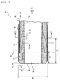
- FIG. 2 is a partial schematic vertical sectional view illustrating a catheter 10 of a first modified example of this embodiment.
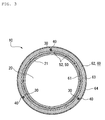
- FIG. 3 is a sectional view (transverse sectional view) taken along line III-III in FIG. 2 .
- the catheter 10 of this embodiment has a tubular body (sheath 16) and operating wires 40.
- the sheath 16 has a main lumen 20, and sub-lumens 30 having a diameter smaller than that of the main lumen 20, respectively formed in the longitudinal direction so as to extend therethrough.
- Each operating wire 40 is laid through each sub-lumen 30 in a slidable manner, with the end thereof fixed to the distal end section 15 of the sheath 16.
- the sheath 16 of this embodiment is configured by a first resin layer 61 and a second resin layer 62 having a hardness higher than that of the first resin layer 61, stacked in the thickness-wise direction, each of which composed of a resin material. In the sheath 16, the thickness of the second resin layer 62 increases from the distal end side towards the proximal end side.
- the sheath 16 herein may have another resin layer, in addition to the first resin layer 61 and the second resin layer 62, in the thickness-wise direction or in the axial direction, as illustrated in FIG. 2 .
- the catheter 10 of the first modified example illustrated in FIG. 2 has a third resin layer 63, in addition to the first resin layer 61 and the second resin layer 62, so as to be stacked in the thickness-wise direction.
- the catheter 10 of this embodiment has a plurality of sub-lumens 30 arranged along a circumference of the main lumen 20 in a discrete manner. More specifically, three sub-lumens 30 are arranged around the main lumen 20 at 120° intervals, and each of the sub-lumens 30 has the operating wire 40 laid therethrough one-by-one in a freely slidable manner.
- the distal end section 15 of the catheter 10 herein means a predetermined length of region of the catheter 10 which includes the distal end DE.
- the proximal end section 17 (see FIG. 4 ) of the catheter 10 herein means a predetermined length of region of the catheter 10 which includes the proximal end PE.
- the catheter 10 of this embodiment is intended for use while being laid through an endoscope inserted into body cavity.
- the distal end section 15 of the catheter 10 is projected out from the end of the endoscope, so as to allow the catheter 10 to advance in a desired direction while bending the distal end section 15 thereof in the body cavity.
- the sheath 16 is configured by a stack of a tubular inner layer 21 which is composed of a resin material and has a main lumen 20 formed therein, an outer layer 60 formed around the inner layer 21, and a hydrophilic coated layer 64 formed as an outermost layer of the catheter 10.
- the coated layer 64 is formed so as to cover the distal end section 15 of the catheter 10, over a longitudinal portion thereof which projects out from the end of the endoscope.
- the coated layer 64 is formed using a hydrophilic resin material such as polyvinyl alcohol (PVA) and polyvinylpyrrolidone, or a resin material having an lubricated outer surface, and is configured to be hydrophilic at least on the outer surface thereof.
- a ring-formed marker 66 composed of a material impermeable against radioactive ray such as X-ray. More specifically, the marker component 66 may be composed of a metal material such as platinum. The marker component 66 in this embodiment is provided around the main lumen 20 and inside the outer layer 60.
- the outer layer 60 of this embodiment is configured by stacking a plurality of resin layers in the thickness-wise direction, or radial direction. More specifically, the catheter 10 of this embodiment illustrated in FIG. 1 , the first and second resin layers 61, 62 are stacked in this order when viewed from the inner side of the radial direction. In other words, in the outer layer 60, the first resin layer 61 configures the inner layer, and the second resin layer 62 configures the outer layer. On the other hand, in the catheter 10 of the modified example illustrated in FIGs. 2 and 3 , the first, third, and second resin layers 61, 63, 62 are stacked in this order when viewed from the inner side of the radial direction. In other words, in the outer layer 60, the first resin layer 61 configures the innermost layer, and the second resin layer 62 configures the outermost layer provided on the outer circumferential side of the first resin layer 61.
- the first to third resin layers 61 to 63 are configured by first to third resin materials 121 to 123, respectively.
- Each of the first to third resin materials 121 to 123 is composed of a single species, or a plurality of species of resin materials.
- the hardness at normal temperature decreases in the order of the second resin material 122, the third resin material 123, and down to the first resin material 121.
- the third resin layer 63 having an intermediate hardness between those of the first resin layer 61 and the second resin layer 62, is stacked between the first resin layer 61 and the second resin layer 62.
- hardness used without special comment in this embodiment, means Shore hardness.
- Thermoplastic polymer may widely be adoptable to each of the first to third resin materials 121 to 123.
- a single species, or two or more species, selected from polyimide (PI), polyamide-imide (PAI), polyethylene terephthalate (PET), polyethylene (PE), polyamide (PA), nylon elastomer, polyurethane (PU), ethylene-vinyl acetate resin (EVA), polyvinyl chloride (PVC) and polypropylene (PP), may be adoptable.
- the same or different materials may be selected from those listed in the above for the first to third resin materials 121 to 123, so that they will have the hardness at normal temperature in a decreasing order of second, third and first resin materials.
- the hardness of the first to third resin material 121 to 123 may be varied from each other, by modifying the degree of polymerization, degree of cross-linkage or species of cross-linking agent.
- the first to third resin materials 121 to 123 may be prepared by mixing a plurality of species of polymers, or may be added with an inorganic filler.
- the first to third resin materials 121 to 123 may have different values of hardness by varying ratio of mixing of a plurality of species of polymers, or varying species or amount of filler to be added.
- the second resin material 122 it is preferable for the second resin material 122 to adopt a resin material having the lowest tackiness as compared with those of the first and the third resin materials 121, 123. It is further preferable to select the materials so that the bending rigidity at normal temperatures decreases in the order of the second, third, and first resin material.
- the thickness of the second resin layer 62 increases from the distal end side of the catheter 10 (left in FIGs. 1 , 2 ) towards the proximal end side (right in the same). It is now defined that "the thickness of the resin layer increases from the distal end side of the catheter 10 towards the proximal end side” means that the thickness of the resin layer is kept uniform, or increases towards the proximal end side herein. Note that the description does not exclude the case where there is some decrease in the thickness of the resin layer towards the proximal end side only in a local longitudinal range, so long as functions of the present invention will not be impaired.
- the thickness of the first resin layer 61 monotonously decreases from the distal end side towards the proximal end side of the sheath 16. Note that “the thickness of the resin layer monotonously decreases (increases)” herein means that the thickness of the resin layer is kept constant, or decreases (increases).
- the distal end section 15 of the catheter 10 of this embodiment illustrated in FIG. 1 has a ratio of the thickness of the first resin layer 61 relative to the thickness of the outer layer 60 monotonously decreases from the distal end DE towards the proximal end PE.
- a ratio of the thickness of the second resin layer 62 relative to the thickness of the outer layer 60 monotonously increases from the distal end DE towards the proximal end PE.
- the first resin layer 61 and the second resin layer 62 have nearly an equal thickness at length-L position away from the distal end DE. Accordingly, in the outer layer 60, the thickness and the bending rigidity of the first resin layer 61 are dominant over the length-L region continued from the distal end DE.
- the thickness and the bending rigidity of the second resin layer 62 are dominant.
- a portion between the intermediate portion in the axial direction of the outer layer 60 and the proximal end section 17 (see FIG. 4 ) is configured substantially by the second resin layer 62 only.
- the thickness of each resin layer may be calculated, by measuring the thickness of the resin layer at a plurality of points on a cross section of the sheath 16 cut normal to the axial direction thereof (see FIG. 3 ), and by finding an average value.
- length L is preferably 10 times or more and 700 times or less as large as the outer diameter d, and more preferably 50 times or more and 350 times or less.
- the hardness gradation may be well balanced between the kink resistance and pressure response, and thereby bending manipulability and selective insertability into blood vessel of the distal end section 15 may particularly be improved.
- the first resin layer 61 has a thickness larger than those of the second resin layer 62 and the third resin layer 63 in the vicinity of the distal end DE of the sheath 16.
- the thickness of the third resin layer 63 once gradually increases and then gradually decreases from the distal end side towards the proximal end side of the sheath 16.
- the first resin layer 61 and the third resin layer 63 have the same thickness.
- the thickness and the bending rigidity of the first resin layer 61 are dominant, over the range thereof from the distal end DE up to the length-L1 position away therefrom.
- the first resin layer 61 and the second resin layer 62 have nearly equal thickness.
- the third resin layer 63 at the length-L position is formed thicker than the first resin layer 61 and the second resin layer 62. Over the range between the length-L1 position and the length-L position, total of the thickness of the first resin layer 61 and the third resin layer 63, and total of the bending rigidity are dominant.
- the second resin layer 62 and the third resin layer 63 have nearly equal thickness.
- relation among the lengths L, L1 and L2 is given as L1 ⁇ L ⁇ L2. In the outer layer 60, the total thickness and the total bending rigidity of the third resin layer 63 and the second resin layer 62 are dominant, over the range from the length-L position up to the length-L2 position.
- the second resin layer 62 which configures the outermost layer is thickest.
- Length L2 is larger than length L1 .
- the thickness and the bending rigidity of the second resin layer 62 are dominant, on the base side of the length-L2 position.
- Each of the first to third resin layers 61 to 63 has the thickness continuously varied from the distal end side towards the proximal end side of the sheath 16, and the bending rigidity of the outer layer 60 is continuous in the longitudinal direction. Accordingly, the amount of flexion of the distal end section 15 may continuously increase relative to the length of pulling of the operating wire 40, and thereby the distal end section 15 may readily move by a desired amount of flexion.
- the length L is preferably 10 times or more and 700 times or less as large as the outer diameter d, and more preferably 50 times or more and 350 times or less.
- length L1 is larger than length L, and preferably 5 times or more and 300 times or less as large as the outer diameter d, and is more preferably 20 times or more and 200 time or less.
- Length L2 is larger than length L, and preferably 25 times or more and 1400 times or less as large as the outer diameter d, and more preferably 100 times or more and 360 times or less.
- the first resin layer 61 it is preferable to configure the first resin layer 61 to have a Shore hardness of 20D to 60D, the second resin layer 62 to have a Shore hardness of 65D to 85D, and to adjust length L to 100 times or more and 290 times or less as large as the outer diameter d.
- the hardness gradation may be well balanced between the kink resistance and pressure response, and thereby bending manipulability and selective insertability into blood vessel of the distal end section 15 may particularly be improved.
- the catheter 10 of this embodiment additionally has the tubular inner layer 21 having the main lumen 20 formed therein, and a braid layer 50 configured by wires 52 woven around the inner layer 21.
- the first resin layer 61 is provided in close contact with the braid layer 50. More specifically, in the sheath 16 of this embodiment, the first resin layer 61 configures the innermost layer of the outer layer 60, with a thickness enough to cover the wires 52 of the braid layer 50.
- Fluorine-containing thermoplastic polymer material may be adoptable to the inner layer 21. More specifically, polytetrafluoroethylene (PTFE), polyvinylidene fluoride (PVDF), perfluoroalkoxy (PFA) and so forth may be adoptable. Adoption of the fluorine-containing resin to the inner layer 21 improves the delivery performance of the catheter 10, in the process of delivering a contrast medium, chemical liquid, and so forth through the main lumen 20 to a diseased site.
- PTFE polytetrafluoroethylene
- PVDF polyvinylidene fluoride
- PFA perfluoroalkoxy
- metal thin wire composed of stainless steel (SUS) or nickel-titanium alloy, or polymer thin fiber composed of PI, PAI PET, and so forth may be adoptable.
- Cross-sectional geometry of the wire 52 is not specifically limited, while allowing adoption of round wire and flat wire.
- Each sub-lumen 30 having the operating wire 40 laid therethrough is formed so as to extend through the outer layer 60, on the outer circumferential side of the center in the thickness-wise direction.
- the sub-lumens 30 are formed through the first resin layer 61 ( FIG. 1 ) or the third resin layer 63 ( FIG. 2 ) so as to extend therethrough, over a predetermined longitudinal range in the vicinity of the distal end DE.
- the sub-lumens 30 are formed so as to extend through the second resin layer 62.
- each sub-lumen 30 having each operating wire 40 laid therethrough is formed in the outer layer 60, and on the outer circumferential side of the braid layer 50.
- Each sub-lumen 30 is provided in the longitudinal direction of the catheter 10 (left/right direction in FIGs. 1 , 2 ), and at least the proximal end section 17 (see FIG. 4 ) of the catheter 10 opens therein.
- the sub-lumens 30 of this embodiment have a continuous round tubular geometry, and are formed at a predetermined radial position away from the center of the main lumen 20.
- the resin material around the sub-lumen 30 of this embodiment illustrated in FIG. 1 phases from the first resin layer 61 (first resin material 121) into the second resin layer 62 (second resin material 122).
- the resin material around the sub-lumen 30 phases from the first resin layer 61 (first resin material 121), through the third resin layer 63 (third resin material 123), into the second resin layer 62 (second resin material 122), when viewed from the distal end side towards the proximal end side.
- the sub-lumens 30 of this embodiment are formed in the outer layer 60, so as to give a straight tube form in the axial direction of the sheath 16.
- the sub-lumens 30 in the present invention may, however, have a geometry other than the straight tube, such as a bent tube spirally wound around the main lumen 20.
- Each sub-lumen 30 is a through-hole formed so as to extend through the outer layer 60.
- the inner wall surface of each sub-lumen 30 of this embodiment is configured by the first to third resin layers 61 to 63.
- the present invention is, however, not limited thereto, instead allowing embedding of a hollow tube for forming the sub-lumen 30 in the outer layer 60.
- the end (distal end) of the operating wire 40 is fixed to the distal end section 15 of the catheter 10.
- Mode of fixation of the end of the operating wire 40 to the distal end section 15 is not specifically limited.
- the end of the operating wire 40 may be tied to the marker 66, or may be fused with the distal end section 15 of the sheath 16, or may be adhered to the marker 66 or to the distal end section 15 of the sheath 16 using an adhesive.
- the operating wire 40 is composed of a very thin wire material, pulling of the proximal end 41 (see FIG. 4 ) of which causes bending of the distal end section 15 of the sheath 16. Bending of the sheath 16 in this embodiment includes L-shape folding and bow-like curving.
- Materials adoptable to the operating wire 40 used for the present method include polymer fibers composed of polyether ether ketone (PEEK), polyphenylene sulfide (PPS), polybutylene terephthalate (PBT), PI, PTFE and so forth; and flexible metal wires such as SUS, corrosion resistance coated steel wire, titanium, titanium alloy and so forth.
- Diameter of the operating wire 40 is preferably 30 to 60 ⁇ m. By virtue of such thinness, the operating wire 40 may readily buckle, when it is pushed into the sheath 16. Accordingly, the catheter 10 of this embodiment is substantially exempt from being applied with pressing force in the distal end section 15 thereof, and will not protrude out from the distal end DE even if the operating wire 40 should detach from the distal end section 15.
- Radius of the main lumen 20 is approximately 200 to 300 ⁇ m
- thickness of the inner layer 21 is approximately 10 to 30 ⁇ m
- thickness of the outer layer 60 is approximately 100 to 150 ⁇ m
- thickness of the braid layer 50 is approximately 20 to 30 ⁇ m.
- Radial distance between the axial center of the catheter 10 and the center of each sub-lumen 30 is approximately 300 to 350 ⁇ m
- inner dimension (diameter) of the sub-lumen 30 is 40 to 100 ⁇ m.
- Outermost dimension (radius) of the catheter 10 is approximately 350 to 450 ⁇ m
- the outer diameter d is smaller than 1 mm. Accordingly, the catheter 10 of this embodiment may be insertable in blood vessels such as celiac artery.
- FIG. 4 is a side elevation for explaining operations of the catheter 10 of this embodiment.
- FIG. 4(a) is a schematic vertical sectional view illustrating the catheter 10 in the natural state, or non-pulled state of the operating wire 40.
- FIG. 4(b) is a schematic vertical sectional view illustrating the catheter 10 with the operating wire 40 thereof pulled. Note that the individual drawings of FIG. 4 illustrate only one of three operating wires 40 in the catheter 10 of this embodiment.
- the proximal end 41 of the operating wire 40 protrudes out from the sub-lumen 30 towards the proximal end side.
- an operating unit 70 for pulling the operating wire 40 so as to bend the distal end section 15 of the catheter 10. Detailed illustration and explanation of a configuration of the operating unit 70 will not be given.
- the operating unit 70 pulls a single operating wire 40, or a plurality of the operating wires 40 at a time.
- tensile force will be applied to the distal end section 15 of the catheter 10, when the proximal end 41 of the operating wire 40 is pulled towards the base side (right in the drawing). If the tensile force is as large as a predetermined level or above, the distal end section 15 will bend from the axial center of the catheter 10 towards the sub-lumen 30 (upward in the drawing) having the pulled operating wire 40 laid therethrough. By independently controlling the length of pulling of each of three operating wires 40, the distal end section 15 of the catheter 10 may be bent in any directions with a 360 degree circle,.
- the direction of advancement of the catheter 10 may freely be controlled only by pulling of the operating wires 40 by the operating unit 70, rather than by torque operation which causes axial rotation of the entire body of the catheter 10. Accordingly, the catheter 10 of this embodiment may be advanced in a desired direction, typically in body cavity such as branched blood vessel.
- the thickness of each of the first resin layer 61 and the second resin layer 62, which composes the outer layer 60 continuously varies in the longitudinal direction.
- the flexibility of the catheter 10 continuously increases from the proximal end PE towards the distal end DE, and conversely the bending rigidity of the catheter 10 increases from the distal end DE towards the proximal end PE. Since the proximal end PE where moment ascribable to the self weight may most heavily be loaded has a large rigidity as described in the above, so that the catheter 10 of this embodiment is now excellent in the geometrical stability, and has a good resilience.
- the distal end section 15 may be bent by a subtle manipulation through the operating wire 40.
- the rigidity of the sheath 16 is continuously varied, by modulating the thickness of the resin layers respectively having different levels of hardness. Accordingly, the sheath 16 may be molded using only a few species of materials.
- the third resin layer 63 having an intermediate hardness between those of the first resin layer 61 and the second resin layer 62, is formed in between. Accordingly, the first resin layer 61 and the second resin layer 62 may be prevented from separating in the process of molding of the outer layer 60 or in the process of bending manipulation of the catheter 10, even if the first resin layer 61 and the second resin layer 62 were adjusted to have largely different levels of hardness.
- the second resin layer 62 having a large hardness is provided on the outer circumferential side of the first resin layer 61. Accordingly, the sheath 16 may be given a good toughness, and thereby the catheter 10 may be improved in the durability. Since the second resin layer 62 composing the outermost layer of the outer layer 60 has a tackiness smaller than those of the first resin layer 61 and the third resin layer 63, so that the catheter 10 may be given a good manipulability when it is inserted through an endoscope.
- the wires 52 composing the braid layer 50 are in close contact with the first resin layer 61.
- the first resin layer 61 is softer than the second resin layer 62 and the third resin layer 63, and is therefore more adherent to the wires 52. Accordingly, the outer layer 60 and the braid layer 50 may be suppressed from separating from each other.
- each sub-lumen 30 having each operating wire 40 laid therethrough is formed on the outer circumferential side of the first resin layer 61.
- the inner wall surface of each sub-lumen 30, which allows each operating wire 40 to slide therethrough is configured by the second resin layer 62 or the third resin layer 63 having hardness higher than that of the first resin layer 61, enough to ensure a good slidability of the operating wire 40.
- the method relates to a method of manufacturing the catheter 10 (see FIG. 1 ) having the sheath 16 which has a main lumen 20, and sub-lumens 30 having a diameter smaller than that of the main lumen 20, both of which being formed in the longitudinal direction so as to extend therethrough; and operating wires 40 laid through the sub-lumens 30 in a slidable manner.
- the method includes a body forming step for forming the sheath 16, by co-extruding a molten first resin material (first resin material 121), together with a molten second resin material (second resin material 122) having a hardness higher than that of the first resin material 121 at normal temperature, and having the operating wires 40 introduced therein, from a die 83, while increasing the amount of extrusion D2 of the second resin material 122 relative to the amount of extrusion D1 of the first resin material 121.
- FIG. 5 is a drawing illustrating an overall configuration of a manufacturing apparatus 80 for manufacturing the sheath 16 used for the method. Both of the catheter 10 of this embodiment (see FIG. 1 ) and the modified example (see FIG. 2 ) may be manufactured using the manufacturing apparatus 80.
- the manufacturing apparatus 80 is configured by an extruder 82, a sizer 84, and a take-up device 86 arranged in series.
- the extruder 82 is an apparatus configured to accept loading of the first and second resin materials 121, 122, and to extrude the outer layer 60 of the sheath 16 in the form of thin tube, out from the die 83.
- the sizer 84 is an apparatus configured to cool the sheath 16 extruded from the extruder 82 so as to give a predetermined diameter, to which a water tank may be adoptable for example.
- the take-up device 86 is composed of rollers driven in an opposed manner, and is configured to take up the end of the sheath 16, extruded from the extruder 82 and then cooled by the sizer 84, at a predetermined take-up speed.
- the sheath 16 to be molded is adjusted to have a predetermined diameter, by adjusting parameters such as rate of taking-up by the take-up device 86, rate of cooling by the sizer 84, distance between the die 83 and the sizer 84, and so forth.
- FIG. 6 is a schematic vertical sectional view illustrating the extruder 82.
- a method of manufacturing the catheter 10, illustrated in FIGs. 2 and 3 , using the extruder 82 will be explained below.
- the first to third resin materials 121 to 123 which serve as major constituents of the sheath 16, are extruded around the core wire 22 to form the sheath 16.
- the core wire 22 is a mandrel formed into a cylindrical geometry, and is a component used for forming the main lumen 20, while being drawn out from the sheath 16.
- the core wire 22 optionally has a mold releasing treatment on the circumferential surface thereof.
- the mold releasing treatment may be given by coating a mold releasing agent such as fluorine-containing one or silicone-based one, or by optical or chemical surface treatment.
- materials for composing the core wire 22 are not specifically limited, metal materials may preferably be used from the viewpoint of large tensile strength and corrosion resistance. More specifically, copper or copper alloy; alloy steels such as carbon steel, stainless steel (SUS) and so forth; and nickel or nickel alloy may be exemplified.
- the circumferential surface of the core wire 22 is preliminarily given the inner layer 21 and the braid layer 50 formed therearound.
- the first to third resin materials 121 to 123 are extruded onto the surface of the braid layer 50, and thereby the outer layer 60 is formed.
- the braid layer 50 is contained in the outer layer 60 as illustrated in FIG. 2 .
- the extruder 82 has the die 83, and flow control valves 92a to 92c.
- the die 83 has three lines of flow paths 91a to 91c through which the first to third resin materials 121 to 123 in molten states are respectively extruded.
- the flow control valves 92a to 92c may increase or decrease the flow rates of the first to third resin materials 121 to 123 at desirable levels.
- the die 83 has a through-hole 97, through which the core wire 22 is inserted, formed at the axial center thereof so as to extend therethrough.
- the core wire 22 is fed into the through-hole 97 at a predetermined speed.
- Direction of feeding of the core wire 22 is leftward in the drawing, as indicated by an arrow.
- the flow path 91a has an expanding diameter portion 94 formed on the upstream side of an output port 93a in the vicinity thereof.
- the expanding diameter portion 94 in the flow path 91a, the amount of extrusion D1 of the first resin material 121 may be stabilized. Accordingly, the braid layer 50 provided on the surface of the core wire 22 may stably be covered with the first resin material 121.
- FIG. 6 exemplifies the die 83 having the expanding diameter portion 94 formed only in the flow path 91a, a cavity may be formed also in the flow paths 91b and 91c, similarly on the upstream side of the output ports 93b and 93c in the vicinity thereof.
- the output port 93a of the flow path 91a is provided on the inner circumferential side closest to the surface of the core wire 22.
- the output port 93c of the flow path 91c, and the output port 93b of the flow path 91b are provided in this order. Accordingly, the first resin material 121 discharged through the output port 93a is extruded onto the outer circumferential surface of the core wire 22.
- the third resin material 123 is discharged through the output port 93c onto the outer circumferential surface of the first resin material 121, and the second resin material 122 is discharged further thereon through the output port 93b.
- the first to third resin materials 121 to 123 discharged through the flow paths 91a to 91c form a three-layered stack in a cavity 95, then shaped by a nozzle 96 at the end of the die 83 so as to give a predetermined thickness, and coated on the surface of the core wire 22.
- the first to third resin materials 121 to 123 extruded out from the nozzle 96 are cooled and cured, and respectively form the first to third resin layers 61 to 63.
- the outer layer 60 is formed over the surface of the core wire 22.
- the operating wire 40 is extruded together with the resin materials. More specifically, as illustrated in FIG. 6 , out from the die 83 of this embodiment, the operating wire 40 is extruded together with the second resin material 122 through the flow path 91b. In this way, the operating wires 40 laid in the longitudinal direction of the sheath 16 are embedded in the outer layer 60.
- the first to third resin materials 121 to 123 are extruded so as to mold the sheath 16.
- the amount of extrusion of the resin material herein means a volumetric flow rate of the resin material extruded out from the nozzle 96 of the die 83 per unit time.
- the outer layer 60 may be molded from the distal end side towards the proximal end side, or from the proximal end side towards the distal end side.
- the present method an exemplary case of extrusion from the distal end side towards the proximal end side will be explained.
- the first resin layer 61 when viewed from the distal end DE (left in the drawing) towards the proximal end PE (right in the drawing), the first resin layer 61 gradually decreases, whereas the second resin layer 62 gradually increases.
- the third resin layer 63 gradually increases and then decreases. Assuming a position distant by a predetermined length away from the distal end DE as a boundary, each of the first to third resin layers 61 to 63 has an approximately uniform thickness on the proximal end PE side of the boundary position.
- the amounts of extrusion D1 to D3 of the first to third resin materials 121 to 123 are adjusted typically as described below, by open/close operation of the flow control valves 92a to 92c of the die 83.
- the amounts of extrusion D1 to D3 may be adjustable by speed of drawing of the core wire 22 by the take-up device 86 (see FIG. 5 ), aperture of the flow control valves 92a to 92c of the die 83, or feeding pressure of the first to third resin materials 121 to 123 to the flow paths 91a to 91c.
- the first, third, second resin layers 61, 63, 62 are stacked in this order from the bottom to the top over the circumferential surface of the core wire 22, and thereby the outer layer 60 is molded.
- the first extrusion process takes place, after the preliminary extrusion step in which the molten third resin material 123, having the operating wire 40 introduced therein, is extruded together with the molten second resin material 122 from the die 83.
- the first to third resin materials 121 to 123 are extruded together from the die 83 so as to mold the sheath 16, while increasing the amount of extrusion D2 of the second resin material 122, relative to the amounts of extrusion D1, D3 of the first and third resin materials 121, 123.
- the second resin layer 62 in the preliminary extrusion step of the present method, is formed to give a thin layer in the vicinity of the distal end DE of the sheath 16, while adjusting the amount of extrusion D2 of the second resin material 122 to not-zero, the present invention is not limited thereto.
- the preliminary extrusion step only the first resin material 121 and the third resin material 123 may be extruded.
- open and close operations of the flow control valves 92a, 92b of the die 83 may be as the following.
- the initial (preliminary) extrusion process only the first resin material 121 is extruded over a predetermined length.
- the distal end section 15 is extrusion-molded while gradually decreasing the amount of extrusion D1 of the first resin material 121, and gradually increasing the amount of extrusion D2 of the second resin material 122.
- a relation D1 ⁇ D2 holds.
- the operating wire 40 is embedded in the surficial portion of the outer layer 60, while being laid through the flow path 91b, and guided by the second resin material 122.
- the operating wire 40 introduced through the flow path 91b and having the end thereof reached the cavity 95, is extruded out through the nozzle 96, while being covered therearound with the third resin material 123.
- the operating wire 40 is consequently extruded out through the nozzle 96, while being covered therearound with the second resin material 122. Accordingly, as illustrated in FIG. 2 , the operating wire 40 is embedded in the third resin layer 63 in the vicinity of the distal end DE of the outer layer 60 of this embodiment, whereas in the second resin layer 62 in the proximal end PE side.
- Method of providing the clearance between the operating wire 40, and the second or third resin material 122, 123 is not specifically limited.
- the operating wire 40 may be inserted through the flow path 91b, while being covered with a filler material 44 provided so as to surround it in the radial direction, and then extruded together with the third resin material 123 or the second resin material 122.
- Liquid or soluble solid may be adoptable to the filler material 44.
- Solid filler material 44 may be exemplified by water-soluble or solvent-soluble solid materials, and more specifically by polyvinyl alcohol (PVA), partially saponified product of polyvinyl acetate, polyacrylic acid, polyacrylamide, polyethylene oxide, and biodecomposable resin such as starch.
- PVA polyvinyl alcohol
- the sub-lumen 30 may be formed in the outer layer 60 so as to extend therethrough, and thereby the sub-lumen 30 and the operating wire 40 are made slidable relative to each other.
- Another possible method of providing the clearance between the operating wire 40, and the second or third resin material 122, 123 may be such as extruding the second resin material 122 while blowing a highly pressurized air around the radial circumference of the operating wire 40.
- the core wire 22 is drawn out so as to form the main lumen 20.
- the core wire 22 having a mold releasing treatment shows an interfacial strength effected on the inner layer 21, which is smaller than separation strength of the outer layer 60 effected on the braid layer 50 or on the inner layer 21. For this reason, by drawing the core wire 22 out from the sheath 16, the inner layer 21 and the braid layer 50, having been formed on the circumferential surface of the core wire 22, are left inside the sheath 16.
- the marker 66 is press-fastened on the outer circumference of the distal end section 15 of the sheath 16, and the end of the operating wire 40 is fixed to the marker 66. Then a hydrophilic coated layer 64 is formed on the outer circumference of the outer layer 60, over a partial length on the distal end side thereof.
- the catheter 10 of this embodiment may be obtained in this way.
- FIG. 7 is a partial schematic vertical sectional view illustrating the catheter 10 of a modified example.
- the drawing illustrates a cross section of the end portion of the catheter 10 cut in the longitudinal direction.
- the first resin layer 61 is provided on the outer circumferential side of the second resin layer 62, over a partial length of the sheath 16 on the distal end DE side thereof.
- the second resin layer 62 is formed on the inner side of the first resin layer 61. More specifically, the first resin layer 61, the third resin layer 63 and the second resin layer 62 are stacked in this order when viewed from the outer circumferential side, so as to form the outer layer 60.
- the second resin layer 62 has a uniform thickness in the vicinity of the distal end DE of the sheath 16, and gradually increases beyond a middle point of the length of the distal end section 15.
- the thickness of the third resin layer 63 once gradually increases and then gradually decreases from the distal end side towards the proximal end side of the sheath 16.
- the thickness of the first resin layer 61 decreases from the distal end side towards the proximal end side of the sheath 16.
- the first resin layer 61 is thickest over the range from the distal end DE towards the length-L1 position, so that the thickness and bending rigidity of the first resin layer 61 are dominant in the outer layer 60.
- the second resin layer 62 and the third resin layer 63 have nearly same thickness at the position distant by length L2 (>L1) from the distal end DE.
- the second resin layer 62 is thickest over the range from the position distant by length L2 from the distal end DE towards the proximal end PE, so that the thickness and bending rigidity of the second resin layer 62 are dominant in the outer layer 60.
- the outer layer 60 of this modified example has the same profile of thickness of the first to third resin layers 61 to 63 in the above-described embodiment.
- the first and third resin layers 61, 63 are stacked over a partial length in the vicinity of the distal end DE, and the outer circumferential surface thereof is covered with the hydrophilic coated layer 64. Accordingly, to the outer surface of the sheath 16 which exposes out from the coated layer 64 on the proximal end side, only the second resin layer 62 exposes. In this way, the first and third resin layers 61, 63, having smaller hardness as compared with the second resin layer 62, are protected by the coated layer 64.
- the end of an operating wire 40 is surrounded by the first resin material 121.
- the resin material around the operating wire 40 continuously phases from the first resin material 121, the third resin material 123, and to the second resin material 122, when viewed from the end to the base.
- the first resin material 121 which is a resin material having the smallest hardness, is stacked in the outermost circumferential portion of the outer layer 60.
- the soft first resin material 121 is stacked on the outer circumference farthest from the center of rigidity, or the axial center of the main lumen 20, in the vicinity of the distal end DE. Therefore, bendability of the sheath 16 when the operating wire 40 is pulled may be improved as compared with the above-described embodiment.
- the present invention is not limited thereto. More specifically, the sub-lumens 30 may be formed inside the inner layer 21, and the braid layer 50 may be provided therearound.
- the inner layer 21 may have a dominant thickness in the sheath 16, and the inner layer 21 may be configured by a stacked structure of the first to third resin layers 61 to 63.
- the total thickness of the sheath 16 may be increased from the distal end DE side towards the proximal end PE side. In this way, a sufficient level of bending strength of the proximal end section 17 of the catheter 10, where the largest bending moment is loaded, may be obtained while ensuring a sufficient level of bendability in the distal end section 15 of the catheter 10.
- the catheter 10 of this embodiment have three operating wires 40 laid through the sub-lumens 30 one-by-one in a slidable manner, the present invention is not limited thereto.
- the number of operating wires 40 may be one, two, or four or more.
- the number of sub-lumens 30 may be same with, or different from, the number of operating wires 40. More specifically, a single sub-lumen 30 may have a plurality of operating wire 40 laid therethrough, or a sub-lumen 30 having no operating wire 40 laid therethrough may be provided to the sheath 16.
Landscapes
- Health & Medical Sciences (AREA)
- Life Sciences & Earth Sciences (AREA)
- Engineering & Computer Science (AREA)
- Animal Behavior & Ethology (AREA)
- Veterinary Medicine (AREA)
- Public Health (AREA)
- General Health & Medical Sciences (AREA)
- Biomedical Technology (AREA)
- Heart & Thoracic Surgery (AREA)
- Biophysics (AREA)
- Hematology (AREA)
- Anesthesiology (AREA)
- Pulmonology (AREA)
- Mechanical Engineering (AREA)
- Surgery (AREA)
- Manufacturing & Machinery (AREA)
- Physics & Mathematics (AREA)
- Nuclear Medicine, Radiotherapy & Molecular Imaging (AREA)
- Optics & Photonics (AREA)
- Pathology (AREA)
- Radiology & Medical Imaging (AREA)
- Medical Informatics (AREA)
- Molecular Biology (AREA)
- Epidemiology (AREA)
- Media Introduction/Drainage Providing Device (AREA)
- Rigid Pipes And Flexible Pipes (AREA)
- Materials For Medical Uses (AREA)
Abstract
A main lumen (20) and sub-lumens (30) having a diameter smaller than that of the main lumen (20) are respectively formed in a sheath (16) of a catheter (10) in the longitudinal direction thereof so as to extend therethrough. An operating wire (40) is laid through each sub-lumen (30) in a slidable manner, with the end thereof fixed to the distal end section (15) of the sheath (16). The sheath (16) is configured a first resin layer (61) and a second resin layer (62) having a hardness higher than that of the first resin layer (61), stacked in the thickness-wise direction, each of which being composed of a resin material. In the sheath(16), the thickness of the second resin layer (62) increases from the distal end side towards the proximal end side.
Description
- The present invention relates to a catheter, and a method of manufacturing a catheter.
- Recently, there has been proposed a catheter, the direction of insertion of which into a body cavity is controllable by allowing the distal end section thereof to bend. As one mode of bending of the distal end of the catheter, a known catheter is configured to operate a wire fixed to the distal end, at the proximal end side (see Patent Document 1 below).
The wire (operating wire) laid through a lumen of the body of the catheter (tubular body) has a predetermined rigidity, and the distal end of the tubular body is bent by pushing the wire. The tubular body herein is sectioned in the longitudinal direction into about four or five sections aligned in series, having stepwisely different flexibility, wherein the rigidity increases towards the proximal end side, and conversely the flexibility increases towards the distal end side. According to the description, the catheter is able to largely bend the distal end section thereof when the wire is pushed, while keeping a predetermined level of resilience. -
- [Patent Document 1] Published Japanese Translation of PCT International Publication for Patent Application No.
2007-507305 - In recent years, diameter of catheters has progressively been shrunk, typically in view of insertability into blood vessel, and those having an outer diameter of 1 mm or smaller have been supplied. In this case, from the viewpoint of ensuring a predetermined inner diameter for a main lumen through which any drug and so forth is delivered or any optical component is inserted, it is desired for a sub-lumen, through which an operating wire is laid, to have an inner diameter of as very small as 10 to several tens micrometers.
In such recent catheters, represented by the catheter disclosed in Patent Document 1, having the flexibility stepwisely varied over a plurality of sections aligned in the longitudinal direction thereof, it may be difficult to ensure subtle manipulation through the operating wire. This is because bendability of the catheter is discontinuous at the boundary portions where the flexibility stepwisely varies, although bending rigidity (geometrical moment of inertia) of the tubular body is generally known to be proportional to the fourth power of diameter. For this reason, relation of the length of pushing or pulling of the operating wire, with the amount of flexion of the distal end may be complicated, and it may therefore become difficult to bend the distal end by a predetermined amount of flexion. On the other hand, any trial made on the conventional catheter so as to gradually vary the flexibility of the tubular body over a number of sections aligned in the longitudinal direction thereof, intended for varying the bendability of the tubular body in a substantially continuous manner, may suffer from problems in costs of molding and materials, because a vast variety of materials will necessarily be used. - The present invention is conceived after considering the above-described problems, and is aimed at providing a catheter which allows subtle bending manipulation through the operating wire irrespective of shrinkage of the diameter of sub-lumen, and is readily manufacturable, and a method of manufacturing the same.
- A catheter of the present invention has a tubular body which includes a main lumen, and a sub-lumen having a diameter smaller than that of the main lumen, both of which being formed in a longitudinal direction so as to extend therethrough; and an operating wire laid through the sub-lumen in a slidable manner, with an end thereof fixed to a distal end section of the tubular body. The tubular body is configured by a first resin layer, and a second resin layer having a hardness higher than that of the first resin layer, stacked in the thickness-wise direction, each of which composed of a resin material, with a thickness of the second resin layer increased from a distal end side towards a proximal end side.
- In a more specific embodiment of the catheter of the present invention, the thickness of the first resin layer may monotonously decrease from the distal end side towards the proximal end side of the tubular body.
- In a more specific embodiment of the catheter of the present invention, a third resin layer, having an intermediate hardness between those of the first resin layer and the second resin layer, may be stacked between the first resin layer and the second resin layer.
- In a more specific embodiment of the catheter of the present invention, the second resin layer may be provided in the outer circumferential side of the first resin layer.
- In a more specific embodiment of the catheter of the present invention, the resin material composing the second resin layer may have a tackiness smaller than that of the resin material composing the first resin layer.
- In a more specific embodiment of the catheter of the present invention, a tubular inner layer having the main lumen formed therein, and a braid layer configured by wires woven around the inner layer, may further be provided, and the first resin layer may be formed in close contact with the braid layer.
- In a more specific embodiment of the catheter of the present invention, the sub-lumen having the operating wire laid therethrough may be formed so as to extend on the outer circumferential side of the first resin layer.
- In a more specific embodiment of the catheter of the present invention, the first resin layer may be provided on the outer circumferential side of the second resin layer, over a partial length of the distal end side of the tubular body.
- A method of manufacturing a catheter of the present invention, which has a tubular body having a main lumen, and a sub-lumen having a diameter smaller than that of the main lumen, both of which being formed in a longitudinal direction so as to extend therethrough; and an operating wire laid through the sub-lumen in a slidable manner, includes a body forming step for forming the tubular body, by co-extruding a molten first resin material, together with a molten second resin material having a hardness higher than that of the first resin material at normal temperature, and having the operating wire introduced therein, from a die, while increasing the amount of extrusion of the second resin material relative to the amount of extrusion of the first resin material.
- In a more specific embodiment of the method of manufacturing a catheter of the present invention, configured to execute the body forming step, after a preliminary extrusion step in which a molten third resin material having the operating wire introduced therein was co-extruded from the die together with the molten second resin material, wherein the tubular body may be formed in the body forming step by co-extruding the first, second and third resin materials from the die, while increasing the amounts of extrusion of the second resin materials relative to the amount of extrusion of the first and third resin material.
- Note that each of various constituents of the present invention may not always necessarily be configured as an independent entity, and instead a plurality of constituents may configure a single component, a single constituents may be configured by a plurality of components, a certain constituent may be a part of other constituent, and a part of certain constituent may be shared with a part of other constituent.
- According to the catheter of the present invention, since the second resin material having the largest hardness is configured to increase the thickness from the distal end side towards the proximal end side thereof, so that subtle manipulation through the operating wire may be ensured, while stably ensuring both of a large resilience of the catheter and a good bendability of the distal end section at the same time.
- The above and other objects, features and advantages of the present invention will be more apparent from the following description of certain preferred embodiments taken in conjunction with the accompanying drawings below.
-
-
FIG. 1 is a partial schematic vertical sectional view illustrating a catheter in one embodiment of the present invention; -
FIG. 2 is a partial schematic vertical sectional view illustrating a catheter of a first modified example of this embodiment; -
FIG. 3 is a sectional view taken along line III-III inFIG. 2 ; -
FIG. 4 is a side elevation for explaining operations of the catheter, wherein (a) is a schematic vertical sectional view illustrating the catheter in the natural state, and (b) is a schematic vertical sectional view illustrating the catheter with the operating wire pulled; -
FIG. 5 is a drawing illustrating an overall configuration of an apparatus for manufacturing a sheath; -
FIG. 6 is a schematic vertical sectional view illustrating an extruder; and -
FIG. 7 is a partial schematic vertical sectional view illustrating a catheter of a second modified example of this embodiment. - Hereinafter, embodiments of the present invention will be explained, referring to the attached drawings. Note that all similar constituents in all drawings will be given similar reference numerals or symbols, so as to occasionally avoid repetitive explanation.
First, a catheter obtainable by a method of manufacturing of this embodiment (hereinafter, occasionally referred to as "the present method") will be outlined, followed by detailed description of the present method. -
FIG. 1 is a partial schematic vertical sectional view illustrating acatheter 10 of this embodiment. The drawing illustrates a cross section of the end portion of thecatheter 10 taken in the longitudinal direction. The left of the drawing corresponds to the distal end (tip) of thecatheter 10, and the right corresponds to the proximal end (base). Note that the proximal end side of thecatheter 10 is not illustrated in this drawing.
FIG. 2 is a partial schematic vertical sectional view illustrating acatheter 10 of a first modified example of this embodiment.
FIG. 3 is a sectional view (transverse sectional view) taken along line III-III inFIG. 2 . - The
catheter 10 of this embodiment has a tubular body (sheath 16) andoperating wires 40.
Thesheath 16 has amain lumen 20, andsub-lumens 30 having a diameter smaller than that of themain lumen 20, respectively formed in the longitudinal direction so as to extend therethrough. Eachoperating wire 40 is laid through eachsub-lumen 30 in a slidable manner, with the end thereof fixed to thedistal end section 15 of thesheath 16.
As illustrated inFIG. 1 , thesheath 16 of this embodiment is configured by afirst resin layer 61 and a second resin layer 62 having a hardness higher than that of thefirst resin layer 61, stacked in the thickness-wise direction, each of which composed of a resin material. In thesheath 16, the thickness of the second resin layer 62 increases from the distal end side towards the proximal end side. - The
sheath 16 herein may have another resin layer, in addition to thefirst resin layer 61 and the second resin layer 62, in the thickness-wise direction or in the axial direction, as illustrated inFIG. 2 . Thecatheter 10 of the first modified example illustrated inFIG. 2 has athird resin layer 63, in addition to thefirst resin layer 61 and the second resin layer 62, so as to be stacked in the thickness-wise direction. - As illustrated in
FIG. 3 , thecatheter 10 of this embodiment has a plurality ofsub-lumens 30 arranged along a circumference of themain lumen 20 in a discrete manner. More specifically, threesub-lumens 30 are arranged around themain lumen 20 at 120° intervals, and each of thesub-lumens 30 has theoperating wire 40 laid therethrough one-by-one in a freely slidable manner.
Note that thedistal end section 15 of thecatheter 10 herein means a predetermined length of region of thecatheter 10 which includes the distal end DE. Similarly, the proximal end section 17 (seeFIG. 4 ) of thecatheter 10 herein means a predetermined length of region of thecatheter 10 which includes the proximal end PE.
Thecatheter 10 of this embodiment is intended for use while being laid through an endoscope inserted into body cavity. Thedistal end section 15 of thecatheter 10 is projected out from the end of the endoscope, so as to allow thecatheter 10 to advance in a desired direction while bending thedistal end section 15 thereof in the body cavity. - The
sheath 16 is configured by a stack of a tubularinner layer 21 which is composed of a resin material and has amain lumen 20 formed therein, anouter layer 60 formed around theinner layer 21, and a hydrophilic coatedlayer 64 formed as an outermost layer of thecatheter 10. - The
coated layer 64 is formed so as to cover thedistal end section 15 of thecatheter 10, over a longitudinal portion thereof which projects out from the end of the endoscope.
Thecoated layer 64 is formed using a hydrophilic resin material such as polyvinyl alcohol (PVA) and polyvinylpyrrolidone, or a resin material having an lubricated outer surface, and is configured to be hydrophilic at least on the outer surface thereof. - In the vicinity of the distal end DE of the
catheter 10, a ring-formedmarker 66, composed of a material impermeable against radioactive ray such as X-ray, is provided. More specifically, themarker component 66 may be composed of a metal material such as platinum. Themarker component 66 in this embodiment is provided around themain lumen 20 and inside theouter layer 60. - The
outer layer 60 of this embodiment is configured by stacking a plurality of resin layers in the thickness-wise direction, or radial direction. More specifically, thecatheter 10 of this embodiment illustrated inFIG. 1 , the first and second resin layers 61, 62 are stacked in this order when viewed from the inner side of the radial direction. In other words, in theouter layer 60, thefirst resin layer 61 configures the inner layer, and the second resin layer 62 configures the outer layer.
On the other hand, in thecatheter 10 of the modified example illustrated inFIGs. 2 and3 , the first, third, and second resin layers 61, 63, 62 are stacked in this order when viewed from the inner side of the radial direction. In other words, in theouter layer 60, thefirst resin layer 61 configures the innermost layer, and the second resin layer 62 configures the outermost layer provided on the outer circumferential side of thefirst resin layer 61. - The first to third resin layers 61 to 63 are configured by first to
third resin materials 121 to 123, respectively. Each of the first tothird resin materials 121 to 123 is composed of a single species, or a plurality of species of resin materials. The hardness at normal temperature decreases in the order of thesecond resin material 122, thethird resin material 123, and down to thefirst resin material 121. - More specifically, in the
sheath 16 of this modified example, thethird resin layer 63, having an intermediate hardness between those of thefirst resin layer 61 and the second resin layer 62, is stacked between thefirst resin layer 61 and the second resin layer 62.
Note that the term "hardness", used without special comment in this embodiment, means Shore hardness. - Thermoplastic polymer may widely be adoptable to each of the first to
third resin materials 121 to 123. For example, a single species, or two or more species, selected from polyimide (PI), polyamide-imide (PAI), polyethylene terephthalate (PET), polyethylene (PE), polyamide (PA), nylon elastomer, polyurethane (PU), ethylene-vinyl acetate resin (EVA), polyvinyl chloride (PVC) and polypropylene (PP), may be adoptable. - The same or different materials may be selected from those listed in the above for the first to
third resin materials 121 to 123, so that they will have the hardness at normal temperature in a decreasing order of second, third and first resin materials.
For the case where the same species of polymer was selected, the hardness of the first tothird resin material 121 to 123 may be varied from each other, by modifying the degree of polymerization, degree of cross-linkage or species of cross-linking agent.
The first tothird resin materials 121 to 123 may be prepared by mixing a plurality of species of polymers, or may be added with an inorganic filler. The first tothird resin materials 121 to 123 may have different values of hardness by varying ratio of mixing of a plurality of species of polymers, or varying species or amount of filler to be added. - It is preferable for the
second resin material 122 to adopt a resin material having the lowest tackiness as compared with those of the first and thethird resin materials - As illustrated in
FIGs. 1 ,2 , the thickness of the second resin layer 62 increases from the distal end side of the catheter 10 (left inFIGs. 1 ,2 ) towards the proximal end side (right in the same). It is now defined that "the thickness of the resin layer increases from the distal end side of thecatheter 10 towards the proximal end side" means that the thickness of the resin layer is kept uniform, or increases towards the proximal end side herein. Note that the description does not exclude the case where there is some decrease in the thickness of the resin layer towards the proximal end side only in a local longitudinal range, so long as functions of the present invention will not be impaired. - In the
catheter 10 of this embodiment, the thickness of thefirst resin layer 61 monotonously decreases from the distal end side towards the proximal end side of thesheath 16.
Note that "the thickness of the resin layer monotonously decreases (increases)" herein means that the thickness of the resin layer is kept constant, or decreases (increases). - The
distal end section 15 of thecatheter 10 of this embodiment illustrated inFIG. 1 has a ratio of the thickness of thefirst resin layer 61 relative to the thickness of theouter layer 60 monotonously decreases from the distal end DE towards the proximal end PE. On the other hand, a ratio of the thickness of the second resin layer 62 relative to the thickness of theouter layer 60 monotonously increases from the distal end DE towards the proximal end PE.
As illustrated inFIG. 1 , thefirst resin layer 61 and the second resin layer 62 have nearly an equal thickness at length-L position away from the distal end DE.
Accordingly, in theouter layer 60, the thickness and the bending rigidity of thefirst resin layer 61 are dominant over the length-L region continued from the distal end DE. In the region more closer to the proximal end PE, when viewed from the length-L position away from the distal end DE, the thickness and the bending rigidity of the second resin layer 62 are dominant. A portion between the intermediate portion in the axial direction of theouter layer 60 and the proximal end section 17 (seeFIG. 4 ) is configured substantially by the second resin layer 62 only. - The thickness of each resin layer may be calculated, by measuring the thickness of the resin layer at a plurality of points on a cross section of the
sheath 16 cut normal to the axial direction thereof (seeFIG. 3 ), and by finding an average value. - While relation between the outer diameter d and length L of the
catheter 10 illustrated inFIG. 1 are not specifically limited, length L is preferably 10 times or more and 700 times or less as large as the outer diameter d, and more preferably 50 times or more and 350 times or less. In particular, by adjusting thefirst resin layer 61 to have a Shore hardness of 20D to 60D, the second resin layer 62 to have a Shore hardness of 65D to 85D, and length L to be 100 times or more and 290 times or less as large as the outer diameter d, the hardness gradation may be well balanced between the kink resistance and pressure response, and thereby bending manipulability and selective insertability into blood vessel of thedistal end section 15 may particularly be improved. - On the other hand, in the
catheter 10 of the modified example illustrated inFIG. 2 , thefirst resin layer 61 has a thickness larger than those of the second resin layer 62 and thethird resin layer 63 in the vicinity of the distal end DE of thesheath 16. The thickness of thethird resin layer 63 once gradually increases and then gradually decreases from the distal end side towards the proximal end side of thesheath 16. At the length-L1 position away from the distal end DE, thefirst resin layer 61 and thethird resin layer 63 have the same thickness. In other words, in theouter layer 60, the thickness and the bending rigidity of thefirst resin layer 61 are dominant, over the range thereof from the distal end DE up to the length-L1 position away therefrom. - At the length-L position away from the distal end DE, the
first resin layer 61 and the second resin layer 62 have nearly equal thickness. In this modified example, thethird resin layer 63 at the length-L position is formed thicker than thefirst resin layer 61 and the second resin layer 62. Over the range between the length-L1 position and the length-L position, total of the thickness of thefirst resin layer 61 and thethird resin layer 63, and total of the bending rigidity are dominant.
At the length-L2 position which is located more closer to the distal end than the length-L position, the second resin layer 62 and thethird resin layer 63 have nearly equal thickness. In this modified example, relation among the lengths L, L1 and L2 is given as L1<L<L2.
In theouter layer 60, the total thickness and the total bending rigidity of thethird resin layer 63 and the second resin layer 62 are dominant, over the range from the length-L position up to the length-L2 position. - On the proximal end side of the length-L2 position away from the distal end DE, the second resin layer 62 which configures the outermost layer is thickest. Length L2 is larger than length L1 . In the
outer layer 60, the thickness and the bending rigidity of the second resin layer 62 are dominant, on the base side of the length-L2 position. - Each of the first to third resin layers 61 to 63 has the thickness continuously varied from the distal end side towards the proximal end side of the
sheath 16, and the bending rigidity of theouter layer 60 is continuous in the longitudinal direction. Accordingly, the amount of flexion of thedistal end section 15 may continuously increase relative to the length of pulling of theoperating wire 40, and thereby thedistal end section 15 may readily move by a desired amount of flexion. - While relation between the outer diameter d of the
catheter 10, and the length lengths L , L1 and L2 is not specifically limited, the length L is preferably 10 times or more and 700 times or less as large as the outer diameter d, and more preferably 50 times or more and 350 times or less. - On the other hand, length L1 is larger than length L, and preferably 5 times or more and 300 times or less as large as the outer diameter d, and is more preferably 20 times or more and 200 time or less.
Length L2 is larger than length L, and preferably 25 times or more and 1400 times or less as large as the outer diameter d, and more preferably 100 times or more and 360 times or less. - Also for the case of the
catheter 10 containing thethird resin layer 63 according to this modified example (seeFIG. 2 ), it is preferable to configure thefirst resin layer 61 to have a Shore hardness of 20D to 60D, the second resin layer 62 to have a Shore hardness of 65D to 85D, and to adjust length L to 100 times or more and 290 times or less as large as the outer diameter d. By the adjustment, the hardness gradation may be well balanced between the kink resistance and pressure response, and thereby bending manipulability and selective insertability into blood vessel of thedistal end section 15 may particularly be improved. - The
catheter 10 of this embodiment additionally has the tubularinner layer 21 having themain lumen 20 formed therein, and a braid layer 50 configured by wires 52 woven around theinner layer 21. Thefirst resin layer 61 is provided in close contact with the braid layer 50. More specifically, in thesheath 16 of this embodiment, thefirst resin layer 61 configures the innermost layer of theouter layer 60, with a thickness enough to cover the wires 52 of the braid layer 50. - Fluorine-containing thermoplastic polymer material, for example, may be adoptable to the
inner layer 21. More specifically, polytetrafluoroethylene (PTFE), polyvinylidene fluoride (PVDF), perfluoroalkoxy (PFA) and so forth may be adoptable. Adoption of the fluorine-containing resin to theinner layer 21 improves the delivery performance of thecatheter 10, in the process of delivering a contrast medium, chemical liquid, and so forth through themain lumen 20 to a diseased site. - To the wire 52, metal thin wire composed of stainless steel (SUS) or nickel-titanium alloy, or polymer thin fiber composed of PI, PAI PET, and so forth may be adoptable. Cross-sectional geometry of the wire 52 is not specifically limited, while allowing adoption of round wire and flat wire.
- Each sub-lumen 30 having the operating
wire 40 laid therethrough is formed so as to extend through theouter layer 60, on the outer circumferential side of the center in the thickness-wise direction. In this embodiment, the sub-lumens 30 are formed through the first resin layer 61 (FIG. 1 ) or the third resin layer 63 (FIG. 2 ) so as to extend therethrough, over a predetermined longitudinal range in the vicinity of the distal end DE. On the proximal end side ahead of the middle point of thedistal end section 15, the sub-lumens 30 are formed so as to extend through the second resin layer 62. In other words, in thecatheter 10 of this embodiment, each sub-lumen 30 having each operatingwire 40 laid therethrough is formed in theouter layer 60, and on the outer circumferential side of the braid layer 50. - Each sub-lumen 30 is provided in the longitudinal direction of the catheter 10 (left/right direction in
FIGs. 1 ,2 ), and at least the proximal end section 17 (seeFIG. 4 ) of thecatheter 10 opens therein.
Thesub-lumens 30 of this embodiment have a continuous round tubular geometry, and are formed at a predetermined radial position away from the center of themain lumen 20. As a result of the gradual increase in the thickness of the second resin layer 62 from the distal end side towards the proximal end side, the resin material around the sub-lumen 30 of this embodiment illustrated inFIG. 1 phases from the first resin layer 61 (first resin material 121) into the second resin layer 62 (second resin material 122). On the other hand, in thecatheter 10 of the modified example illustrated inFIG. 2 , the resin material around the sub-lumen 30 phases from the first resin layer 61 (first resin material 121), through the third resin layer 63 (third resin material 123), into the second resin layer 62 (second resin material 122), when viewed from the distal end side towards the proximal end side.
Thesub-lumens 30 of this embodiment are formed in theouter layer 60, so as to give a straight tube form in the axial direction of thesheath 16. The sub-lumens 30 in the present invention may, however, have a geometry other than the straight tube, such as a bent tube spirally wound around themain lumen 20. - Each sub-lumen 30 is a through-hole formed so as to extend through the
outer layer 60. The inner wall surface of each sub-lumen 30 of this embodiment is configured by the first to third resin layers 61 to 63. The present invention is, however, not limited thereto, instead allowing embedding of a hollow tube for forming the sub-lumen 30 in theouter layer 60. - The end (distal end) of the
operating wire 40 is fixed to thedistal end section 15 of thecatheter 10. Mode of fixation of the end of theoperating wire 40 to thedistal end section 15 is not specifically limited. For example, the end of theoperating wire 40 may be tied to themarker 66, or may be fused with thedistal end section 15 of thesheath 16, or may be adhered to themarker 66 or to thedistal end section 15 of thesheath 16 using an adhesive. - The
operating wire 40 is composed of a very thin wire material, pulling of the proximal end 41 (seeFIG. 4 ) of which causes bending of thedistal end section 15 of thesheath 16. Bending of thesheath 16 in this embodiment includes L-shape folding and bow-like curving. - Materials adoptable to the
operating wire 40 used for the present method include polymer fibers composed of polyether ether ketone (PEEK), polyphenylene sulfide (PPS), polybutylene terephthalate (PBT), PI, PTFE and so forth; and flexible metal wires such as SUS, corrosion resistance coated steel wire, titanium, titanium alloy and so forth.
Diameter of theoperating wire 40 is preferably 30 to 60 µm. By virtue of such thinness, theoperating wire 40 may readily buckle, when it is pushed into thesheath 16. Accordingly, thecatheter 10 of this embodiment is substantially exempt from being applied with pressing force in thedistal end section 15 thereof, and will not protrude out from the distal end DE even if theoperating wire 40 should detach from thedistal end section 15. - Representative dimensions of the
catheter 10 of this embodiment are typically given below.
Radius of themain lumen 20 is approximately 200 to 300 µm, thickness of theinner layer 21 is approximately 10 to 30 µm, thickness of theouter layer 60 is approximately 100 to 150 µm, and thickness of the braid layer 50 is approximately 20 to 30 µm.
Radial distance between the axial center of thecatheter 10 and the center of each sub-lumen 30 is approximately 300 to 350 µm, and inner dimension (diameter) of the sub-lumen 30 is 40 to 100 µm.
Outermost dimension (radius) of thecatheter 10 is approximately 350 to 450 µm, and the outer diameter d (seeFIG. 2 ) is smaller than 1 mm. Accordingly, thecatheter 10 of this embodiment may be insertable in blood vessels such as celiac artery. -
FIG. 4 is a side elevation for explaining operations of thecatheter 10 of this embodiment.FIG. 4(a) is a schematic vertical sectional view illustrating thecatheter 10 in the natural state, or non-pulled state of theoperating wire 40.FIG. 4(b) is a schematic vertical sectional view illustrating thecatheter 10 with theoperating wire 40 thereof pulled. Note that the individual drawings ofFIG. 4 illustrate only one of three operatingwires 40 in thecatheter 10 of this embodiment. - The
proximal end 41 of theoperating wire 40 protrudes out from the sub-lumen 30 towards the proximal end side. On the proximal end side of theoperating wire 40, there is provided anoperating unit 70 for pulling theoperating wire 40 so as to bend thedistal end section 15 of thecatheter 10. Detailed illustration and explanation of a configuration of the operatingunit 70 will not be given. The operatingunit 70 pulls asingle operating wire 40, or a plurality of the operatingwires 40 at a time. - In the
catheter 10 of this embodiment, tensile force will be applied to thedistal end section 15 of thecatheter 10, when theproximal end 41 of theoperating wire 40 is pulled towards the base side (right in the drawing). If the tensile force is as large as a predetermined level or above, thedistal end section 15 will bend from the axial center of thecatheter 10 towards the sub-lumen 30 (upward in the drawing) having the pulled operatingwire 40 laid therethrough.
By independently controlling the length of pulling of each of three operatingwires 40, thedistal end section 15 of thecatheter 10 may be bent in any directions with a 360 degree circle,. In this way, the direction of advancement of thecatheter 10 may freely be controlled only by pulling of the operatingwires 40 by the operatingunit 70, rather than by torque operation which causes axial rotation of the entire body of thecatheter 10. Accordingly, thecatheter 10 of this embodiment may be advanced in a desired direction, typically in body cavity such as branched blood vessel. - Now, in the
catheter 10 of this embodiment, the thickness of each of thefirst resin layer 61 and the second resin layer 62, which composes theouter layer 60, continuously varies in the longitudinal direction. The flexibility of thecatheter 10 continuously increases from the proximal end PE towards the distal end DE, and conversely the bending rigidity of thecatheter 10 increases from the distal end DE towards the proximal end PE. Since the proximal end PE where moment ascribable to the self weight may most heavily be loaded has a large rigidity as described in the above, so that thecatheter 10 of this embodiment is now excellent in the geometrical stability, and has a good resilience. On the other hand, since a large flexibility may be obtained in the vicinity of the distal end DE of thecatheter 10, thedistal end section 15 may be bent by a subtle manipulation through theoperating wire 40.
In thecatheter 10 of this embodiment, the rigidity of thesheath 16 is continuously varied, by modulating the thickness of the resin layers respectively having different levels of hardness. Accordingly, thesheath 16 may be molded using only a few species of materials. - In the
catheter 10 of the modified example, thethird resin layer 63, having an intermediate hardness between those of thefirst resin layer 61 and the second resin layer 62, is formed in between. Accordingly, thefirst resin layer 61 and the second resin layer 62 may be prevented from separating in the process of molding of theouter layer 60 or in the process of bending manipulation of thecatheter 10, even if thefirst resin layer 61 and the second resin layer 62 were adjusted to have largely different levels of hardness. - In the
catheter 10 of this embodiment, the second resin layer 62 having a large hardness is provided on the outer circumferential side of thefirst resin layer 61. Accordingly, thesheath 16 may be given a good toughness, and thereby thecatheter 10 may be improved in the durability.
Since the second resin layer 62 composing the outermost layer of theouter layer 60 has a tackiness smaller than those of thefirst resin layer 61 and thethird resin layer 63, so that thecatheter 10 may be given a good manipulability when it is inserted through an endoscope. - In the
catheter 10 of this embodiment, the wires 52 composing the braid layer 50 are in close contact with thefirst resin layer 61. Thefirst resin layer 61 is softer than the second resin layer 62 and thethird resin layer 63, and is therefore more adherent to the wires 52. Accordingly, theouter layer 60 and the braid layer 50 may be suppressed from separating from each other. - In the
catheter 10 of this embodiment, each sub-lumen 30 having each operatingwire 40 laid therethrough is formed on the outer circumferential side of thefirst resin layer 61. This means that the inner wall surface of each sub-lumen 30, which allows each operatingwire 40 to slide therethrough, is configured by the second resin layer 62 or thethird resin layer 63 having hardness higher than that of thefirst resin layer 61, enough to ensure a good slidability of theoperating wire 40. - A method of manufacturing a catheter of this embodiment (referred to as "the method") will be detailed below.
The method relates to a method of manufacturing the catheter 10 (seeFIG. 1 ) having thesheath 16 which has amain lumen 20, and sub-lumens 30 having a diameter smaller than that of themain lumen 20, both of which being formed in the longitudinal direction so as to extend therethrough; andoperating wires 40 laid through the sub-lumens 30 in a slidable manner.
The method includes a body forming step for forming thesheath 16, by co-extruding a molten first resin material (first resin material 121), together with a molten second resin material (second resin material 122) having a hardness higher than that of thefirst resin material 121 at normal temperature, and having the operatingwires 40 introduced therein, from adie 83, while increasing the amount of extrusion D2 of thesecond resin material 122 relative to the amount of extrusion D1 of thefirst resin material 121. - The individual processes of the method will further be detailed below, referring to the attached drawings.
FIG. 5 is a drawing illustrating an overall configuration of amanufacturing apparatus 80 for manufacturing thesheath 16 used for the method. Both of thecatheter 10 of this embodiment (seeFIG. 1 ) and the modified example (seeFIG. 2 ) may be manufactured using themanufacturing apparatus 80. - The
manufacturing apparatus 80 is configured by anextruder 82, asizer 84, and a take-updevice 86 arranged in series.
Theextruder 82 is an apparatus configured to accept loading of the first andsecond resin materials outer layer 60 of thesheath 16 in the form of thin tube, out from thedie 83.
Thesizer 84 is an apparatus configured to cool thesheath 16 extruded from theextruder 82 so as to give a predetermined diameter, to which a water tank may be adoptable for example.
The take-updevice 86 is composed of rollers driven in an opposed manner, and is configured to take up the end of thesheath 16, extruded from theextruder 82 and then cooled by thesizer 84, at a predetermined take-up speed.
In themanufacturing apparatus 80, thesheath 16 to be molded is adjusted to have a predetermined diameter, by adjusting parameters such as rate of taking-up by the take-updevice 86, rate of cooling by thesizer 84, distance between the die 83 and thesizer 84, and so forth. -
FIG. 6 is a schematic vertical sectional view illustrating theextruder 82. A method of manufacturing thecatheter 10, illustrated inFIGs. 2 and3 , using theextruder 82 will be explained below.
In the body forming step of the present method, the first tothird resin materials 121 to 123, which serve as major constituents of thesheath 16, are extruded around thecore wire 22 to form thesheath 16.
Thecore wire 22 is a mandrel formed into a cylindrical geometry, and is a component used for forming themain lumen 20, while being drawn out from thesheath 16. - The
core wire 22 optionally has a mold releasing treatment on the circumferential surface thereof. The mold releasing treatment may be given by coating a mold releasing agent such as fluorine-containing one or silicone-based one, or by optical or chemical surface treatment.
While materials for composing thecore wire 22 are not specifically limited, metal materials may preferably be used from the viewpoint of large tensile strength and corrosion resistance. More specifically, copper or copper alloy; alloy steels such as carbon steel, stainless steel (SUS) and so forth; and nickel or nickel alloy may be exemplified. - Prior to the body forming step, the circumferential surface of the
core wire 22 is preliminarily given theinner layer 21 and the braid layer 50 formed therearound.
In the body forming step, the first tothird resin materials 121 to 123 are extruded onto the surface of the braid layer 50, and thereby theouter layer 60 is formed. As a consequence, the braid layer 50 is contained in theouter layer 60 as illustrated inFIG. 2 . - The
extruder 82 has the die 83, and flowcontrol valves 92a to 92c.
Thedie 83 has three lines offlow paths 91a to 91c through which the first tothird resin materials 121 to 123 in molten states are respectively extruded.
Theflow control valves 92a to 92c may increase or decrease the flow rates of the first tothird resin materials 121 to 123 at desirable levels.
Thedie 83 has a through-hole 97, through which thecore wire 22 is inserted, formed at the axial center thereof so as to extend therethrough. Thecore wire 22 is fed into the through-hole 97 at a predetermined speed. Direction of feeding of thecore wire 22 is leftward in the drawing, as indicated by an arrow. - The
flow path 91a has an expandingdiameter portion 94 formed on the upstream side of anoutput port 93a in the vicinity thereof. By virtue of provision of the expandingdiameter portion 94 in theflow path 91a, the amount of extrusion D1 of thefirst resin material 121 may be stabilized. Accordingly, the braid layer 50 provided on the surface of thecore wire 22 may stably be covered with thefirst resin material 121.
WhileFIG. 6 exemplifies the die 83 having the expandingdiameter portion 94 formed only in theflow path 91a, a cavity may be formed also in theflow paths output ports - The
output port 93a of theflow path 91a is provided on the inner circumferential side closest to the surface of thecore wire 22. On the outer circumferential side of theoutput port 93a, theoutput port 93c of theflow path 91c, and theoutput port 93b of theflow path 91b are provided in this order.
Accordingly, thefirst resin material 121 discharged through theoutput port 93a is extruded onto the outer circumferential surface of thecore wire 22. Thethird resin material 123 is discharged through theoutput port 93c onto the outer circumferential surface of thefirst resin material 121, and thesecond resin material 122 is discharged further thereon through theoutput port 93b. - The first to
third resin materials 121 to 123 discharged through theflow paths 91a to 91c form a three-layered stack in acavity 95, then shaped by anozzle 96 at the end of the die 83 so as to give a predetermined thickness, and coated on the surface of thecore wire 22. The first tothird resin materials 121 to 123 extruded out from thenozzle 96 are cooled and cured, and respectively form the first to third resin layers 61 to 63. In short, by extruding the first tothird resin materials 121 to 123 in a three-layered manner out through thenozzle 96, theouter layer 60 is formed over the surface of thecore wire 22. - Out from the
die 83, theoperating wire 40 is extruded together with the resin materials. More specifically, as illustrated inFIG. 6 , out from thedie 83 of this embodiment, theoperating wire 40 is extruded together with thesecond resin material 122 through theflow path 91b.
In this way, the operatingwires 40 laid in the longitudinal direction of thesheath 16 are embedded in theouter layer 60. - In the body forming step of the present method, while increasing the amount of extrusion D2 of the
second resin material 122 relative to the amount of extrusion D1 of thefirst resin material 121, the first tothird resin materials 121 to 123 are extruded so as to mold thesheath 16. The amount of extrusion of the resin material herein means a volumetric flow rate of the resin material extruded out from thenozzle 96 of the die 83 per unit time. - In the body forming step, the
outer layer 60 may be molded from the distal end side towards the proximal end side, or from the proximal end side towards the distal end side. In the present method, an exemplary case of extrusion from the distal end side towards the proximal end side will be explained.
As illustrated inFIG. 2 , in theouter layer 60 of thecatheter 10 of this embodiment, when viewed from the distal end DE (left in the drawing) towards the proximal end PE (right in the drawing), thefirst resin layer 61 gradually decreases, whereas the second resin layer 62 gradually increases. In a similar view, thethird resin layer 63 gradually increases and then decreases. Assuming a position distant by a predetermined length away from the distal end DE as a boundary, each of the first to third resin layers 61 to 63 has an approximately uniform thickness on the proximal end PE side of the boundary position. - In the body forming step, the amounts of extrusion D1 to D3 of the first to
third resin materials 121 to 123 are adjusted typically as described below, by open/close operation of theflow control valves 92a to 92c of thedie 83. - (1) While setting an initial condition to D2=D3≈0, the
first resin material 121 only is extruded from thenozzle 96 so as to mold the distal end DE (initial extrusion process). - (2) Following the initial extrusion process, the first to
third resin materials 121 to 123 are extruded out through thenozzle 96 over a predetermined extrusion length L1 (seeFIG. 2 ), while gradually decreasing D1, and gradually increasing D2 and D3 (preliminary extrusion step). In the final stage of the preliminary extrusion step, a relation of D1≈D3>D2 holds. - (3) Following the preliminary extrusion step, the first to
third resin materials 121 to 123 are extruded out through thenozzle 96, while further gradually decreasing D1, gradually increasing D2, and turning D3 from gradual increase into gradual decrease. At a point of extrusion length L (seeFIG. 2 ), a relation D3>D1≈D2 holds. Furthermore, the first tothird resin materials 121 to 123 are extruded out through thenozzle 96 up to the extrusion length L2 (seeFIG. 2 ), while gradually decreasing D1 and D3, and gradually increasing D2, so as to mold the distal end section 15 (first extrusion process). In the final stage of the first extrusion process, a relation of D2≈D3>D1 holds. - (4) Following the first extrusion process, D1 and D3 are further gradually decreased, and D2 is further gradually increased. While setting the condition to D1=D3≈0, the
second resin material 122 only is then extruded out through thenozzle 96, so as to mold theouter layer 60 up to the proximal end PE (second extrusion process). - The amounts of extrusion D1 to D3 may be adjustable by speed of drawing of the
core wire 22 by the take-up device 86 (seeFIG. 5 ), aperture of theflow control valves 92a to 92c of the die 83, or feeding pressure of the first tothird resin materials 121 to 123 to theflow paths 91a to 91c. - By the extrusion process described in the above, the first, third, second resin layers 61, 63, 62 are stacked in this order from the bottom to the top over the circumferential surface of the
core wire 22, and thereby theouter layer 60 is molded. - In short, according to the present method, the first extrusion process takes place, after the preliminary extrusion step in which the molten
third resin material 123, having the operatingwire 40 introduced therein, is extruded together with the moltensecond resin material 122 from thedie 83.
In the first extrusion process, the first tothird resin materials 121 to 123 are extruded together from the die 83 so as to mold thesheath 16, while increasing the amount of extrusion D2 of thesecond resin material 122, relative to the amounts of extrusion D1, D3 of the first andthird resin materials - Although the second resin layer 62, in the preliminary extrusion step of the present method, is formed to give a thin layer in the vicinity of the distal end DE of the
sheath 16, while adjusting the amount of extrusion D2 of thesecond resin material 122 to not-zero, the present invention is not limited thereto. Alternatively, in the preliminary extrusion step, only thefirst resin material 121 and thethird resin material 123 may be extruded. - For the case where the catheter 10 (see
FIG. 1 ) having theouter layer 60 composed of two layers, which are the first and second resin layers 61, 62, is manufactured, open and close operations of theflow control valves
In the initial (preliminary) extrusion process, only thefirst resin material 121 is extruded over a predetermined length.
Thereafter, in the first extrusion process, thedistal end section 15 is extrusion-molded while gradually decreasing the amount of extrusion D1 of thefirst resin material 121, and gradually increasing the amount of extrusion D2 of thesecond resin material 122. At the time correspondent to extrusion length L, a relation D1≈D2 holds.
Following the first extrusion process, only thesecond resin material 122 is extruded out through thenozzle 96 while setting D1≈0, so as to mold, by extrusion, theouter layer 60 up to the proximal end PE (second extrusion process). - The
operating wire 40 is embedded in the surficial portion of theouter layer 60, while being laid through theflow path 91b, and guided by thesecond resin material 122.
In the preliminary molding process, theoperating wire 40, introduced through theflow path 91b and having the end thereof reached thecavity 95, is extruded out through thenozzle 96, while being covered therearound with thethird resin material 123. Then in the first extrusion process and the second extrusion process, theoperating wire 40 is consequently extruded out through thenozzle 96, while being covered therearound with thesecond resin material 122.
Accordingly, as illustrated inFIG. 2 , theoperating wire 40 is embedded in thethird resin layer 63 in the vicinity of the distal end DE of theouter layer 60 of this embodiment, whereas in the second resin layer 62 in the proximal end PE side. - Now in the body forming step of the present method, close adherence between the operating
wire 40 and theouter layer 60 may be prevented, by providing a clearance between the operatingwire 40, and the second orthird resin material outer layer 60. Accordingly, in thecatheter 10 of this embodiment, slidability between the operatingwires 40 and the sub-lumens 30 may be ensured. - Method of providing the clearance between the operating
wire 40, and the second orthird resin material operating wire 40 may be inserted through theflow path 91b, while being covered with a filler material 44 provided so as to surround it in the radial direction, and then extruded together with thethird resin material 123 or thesecond resin material 122. Liquid or soluble solid may be adoptable to the filler material 44. Solid filler material 44 may be exemplified by water-soluble or solvent-soluble solid materials, and more specifically by polyvinyl alcohol (PVA), partially saponified product of polyvinyl acetate, polyacrylic acid, polyacrylamide, polyethylene oxide, and biodecomposable resin such as starch.
Then in the body forming step, by removing the filler material 44 from the surface of theoperating wire 40 embedded in theouter layer 60, the sub-lumen 30 may be formed in theouter layer 60 so as to extend therethrough, and thereby the sub-lumen 30 and theoperating wire 40 are made slidable relative to each other. - Another possible method of providing the clearance between the operating
wire 40, and the second orthird resin material second resin material 122 while blowing a highly pressurized air around the radial circumference of theoperating wire 40. - From the
sheath 16 having the operatingwires 40 laid through theouter layer 60 in a slidable manner, thecore wire 22 is drawn out so as to form themain lumen 20. Thecore wire 22 having a mold releasing treatment shows an interfacial strength effected on theinner layer 21, which is smaller than separation strength of theouter layer 60 effected on the braid layer 50 or on theinner layer 21. For this reason, by drawing thecore wire 22 out from thesheath 16, theinner layer 21 and the braid layer 50, having been formed on the circumferential surface of thecore wire 22, are left inside thesheath 16. - Next, the
marker 66 is press-fastened on the outer circumference of thedistal end section 15 of thesheath 16, and the end of theoperating wire 40 is fixed to themarker 66. Then a hydrophilic coatedlayer 64 is formed on the outer circumference of theouter layer 60, over a partial length on the distal end side thereof.
Thecatheter 10 of this embodiment may be obtained in this way. - Note that the present invention is not limited to the above-described embodiment, instead allowing various modifications and improvement, so long as the object of the present invention may be accomplished.
-
FIG. 7 is a partial schematic vertical sectional view illustrating thecatheter 10 of a modified example. The drawing illustrates a cross section of the end portion of thecatheter 10 cut in the longitudinal direction.
In this modified example, thefirst resin layer 61 is provided on the outer circumferential side of the second resin layer 62, over a partial length of thesheath 16 on the distal end DE side thereof. - In the
catheter 10 of this modified example, the second resin layer 62 is formed on the inner side of thefirst resin layer 61. More specifically, thefirst resin layer 61, thethird resin layer 63 and the second resin layer 62 are stacked in this order when viewed from the outer circumferential side, so as to form theouter layer 60. - The second resin layer 62 has a uniform thickness in the vicinity of the distal end DE of the
sheath 16, and gradually increases beyond a middle point of the length of thedistal end section 15.
The thickness of thethird resin layer 63 once gradually increases and then gradually decreases from the distal end side towards the proximal end side of thesheath 16.
The thickness of thefirst resin layer 61 decreases from the distal end side towards the proximal end side of thesheath 16. - The
first resin layer 61 is thickest over the range from the distal end DE towards the length-L1 position, so that the thickness and bending rigidity of thefirst resin layer 61 are dominant in theouter layer 60.
On the other hand, the second resin layer 62 and thethird resin layer 63 have nearly same thickness at the position distant by length L2 (>L1) from the distal end DE.
The second resin layer 62 is thickest over the range from the position distant by length L2 from the distal end DE towards the proximal end PE, so that the thickness and bending rigidity of the second resin layer 62 are dominant in theouter layer 60. - In short, the
outer layer 60 of this modified example has the same profile of thickness of the first to third resin layers 61 to 63 in the above-described embodiment. - The first and third resin layers 61, 63 are stacked over a partial length in the vicinity of the distal end DE, and the outer circumferential surface thereof is covered with the hydrophilic coated
layer 64.
Accordingly, to the outer surface of thesheath 16 which exposes out from thecoated layer 64 on the proximal end side, only the second resin layer 62 exposes. In this way, the first and third resin layers 61, 63, having smaller hardness as compared with the second resin layer 62, are protected by thecoated layer 64. - In this modified example, the end of an
operating wire 40 is surrounded by thefirst resin material 121. The resin material around theoperating wire 40 continuously phases from thefirst resin material 121, thethird resin material 123, and to thesecond resin material 122, when viewed from the end to the base. - In this modified example, the
first resin material 121, which is a resin material having the smallest hardness, is stacked in the outermost circumferential portion of theouter layer 60. In other words, in this modified example, the softfirst resin material 121 is stacked on the outer circumference farthest from the center of rigidity, or the axial center of themain lumen 20, in the vicinity of the distal end DE. Therefore, bendability of thesheath 16 when theoperating wire 40 is pulled may be improved as compared with the above-described embodiment. - While the above-descried embodiment exemplified a mode having the sub-lumen 30 formed outside the braid layer 50, the present invention is not limited thereto. More specifically, the sub-lumens 30 may be formed inside the
inner layer 21, and the braid layer 50 may be provided therearound.
In addition, theinner layer 21 may have a dominant thickness in thesheath 16, and theinner layer 21 may be configured by a stacked structure of the first to third resin layers 61 to 63.
By virtue of protection of the outer circumference of the sub-lumens 30 with the braid layer 50 as described in the above, theoperating wire 40 will not break through thecatheter 10 to be exposed externally, even if an excessive tensile force should be applied to theoperating wire 40 during manipulation. - On the other hand, in the present method, by adjusting the take-up speed by the take-up device 86 (see
FIG. 5 ) or extrusion speed of the first tothird resin materials 121 to 123, the total thickness of thesheath 16 may be increased from the distal end DE side towards the proximal end PE side.
In this way, a sufficient level of bending strength of theproximal end section 17 of thecatheter 10, where the largest bending moment is loaded, may be obtained while ensuring a sufficient level of bendability in thedistal end section 15 of thecatheter 10. - While the
catheter 10 of this embodiment have three operatingwires 40 laid through the sub-lumens 30 one-by-one in a slidable manner, the present invention is not limited thereto. The number ofoperating wires 40 may be one, two, or four or more. The number ofsub-lumens 30 may be same with, or different from, the number ofoperating wires 40. More specifically, a single sub-lumen 30 may have a plurality ofoperating wire 40 laid therethrough, or a sub-lumen 30 having no operatingwire 40 laid therethrough may be provided to thesheath 16. - This application claims priority right based on Japanese Patent Application No.
2009-054806 filed on March 9, 2009
Claims (10)
- A catheter comprising:a tubular body comprising a main lumen, and a sub-lumen having a diameter smaller than that of the main lumen, both of which being formed in a longitudinal direction so as to extend therethrough; andan operating wire laid through the sub-lumen in a slidable manner, with an end thereof fixed to a distal end section of the tubular body,the tubular body being configured by a first resin layer and a second resin layer having a hardness higher than that of the first resin layer, each of which being composed of a resin material, stacked in a thickness-wise direction, with a thickness of the second resin layer increased from a distal end side towards a proximal end side.
- The catheter according to Claim 1,
wherein the thickness of the first resin layer monotonously decreases from the distal end side towards the proximal end side of the tubular body. - The catheter according to Claim 1 or 2,
further comprising a third resin layer, having an intermediate hardness between those of the first resin layer and the second resin layer, stacked between the first resin layer and the second resin layer. - The catheter according to any one of Claims 1 to 3,
wherein the second resin layer is provided in the outer circumferential side of the first resin layer. - The catheter according to Claim 4,
wherein the resin material composing the second resin layer has a tackiness smaller than that of the resin material composing the first resin layer. - The catheter according to any one of Claims 1 to 5,
further comprising a tubular inner layer having the main lumen formed therein, and a braid layer configured by wires woven around the inner layer,
wherein the first resin layer is formed in close contact with the braid layer. - The catheter according to any one of Claims 1 to 6,
wherein the sub-lumen having the operating wire laid therethrough is formed so as to extend on the outer circumferential side of the first resin layer. - The catheter according to any one of Claims 1 to 3,
wherein the first resin layer is provided on the outer circumferential side of the second resin layer, over a partial length of the distal end side of the tubular body. - A method of manufacturing a catheter which has a tubular body comprising a main lumen, and a sub-lumen having a diameter smaller than that of the main lumen, both of which being formed in a longitudinal direction so as to extend therethrough; and an operating wire laid through the sub-lumen in a slidable manner, the method comprising:a body forming step for forming the tubular body, by co-extruding a molten first resin material, together with a molten second resin material having a hardness higher than that of the first resin material at normal temperature, and having the operating wire introduced therein, from a die, while increasing the amount of extrusion of the second resin material relative to the amount of extrusion of the first resin material.
- The method of manufacturing a catheter according to Claim 9, configured to execute the body forming step, after a preliminary extrusion step in which a molten third resin material having the operating wire introduced therein was co-extruded from the die together with the molten second resin material,
wherein, in the body forming step, the tubular body is formed by co-extruding the first, second and third resin materials from the die, while increasing the amount of extrusion of the second resin materials relative to the amount of extrusion of the first and third resin material.
Applications Claiming Priority (2)
| Application Number | Priority Date | Filing Date | Title |
|---|---|---|---|
| JP2009054806 | 2009-03-09 | ||
| PCT/JP2010/001532 WO2010103762A1 (en) | 2009-03-09 | 2010-03-05 | Catheter and method of manufacturing catheter |
Publications (2)
| Publication Number | Publication Date |
|---|---|
| EP2407199A1 true EP2407199A1 (en) | 2012-01-18 |
| EP2407199A4 EP2407199A4 (en) | 2014-08-13 |
Family
ID=42728058
Family Applications (1)
| Application Number | Title | Priority Date | Filing Date |
|---|---|---|---|
| EP10750520.8A Withdrawn EP2407199A4 (en) | 2009-03-09 | 2010-03-05 | Catheter and method of manufacturing catheter |
Country Status (6)
| Country | Link |
|---|---|
| US (1) | US20110295217A1 (en) |
| EP (1) | EP2407199A4 (en) |
| JP (1) | JP5696659B2 (en) |
| KR (1) | KR20110139698A (en) |
| CN (1) | CN102341141B (en) |
| WO (1) | WO2010103762A1 (en) |
Families Citing this family (29)
| Publication number | Priority date | Publication date | Assignee | Title |
|---|---|---|---|---|
| DE202011100368U1 (en) * | 2011-05-06 | 2011-07-04 | Novoplast Schlauchtechnik GmbH, 38820 | In the axial direction permanently, any deformable, extruded plastic profile |
| JP6221300B2 (en) * | 2013-03-28 | 2017-11-01 | 住友ベークライト株式会社 | Catheter and catheter operation part |
| CN104902951B (en) * | 2013-07-31 | 2017-09-19 | 奥林巴斯株式会社 | catheter |
| JP6076855B2 (en) * | 2013-08-09 | 2017-02-08 | 川澄化学工業株式会社 | Microcatheter and catheter apparatus |
| US20150352330A1 (en) * | 2014-06-09 | 2015-12-10 | Boston Scientific Scimed, Inc. | Deliver assist device for guide catheter |
| JP7012655B2 (en) | 2016-02-24 | 2022-01-28 | インセプト、リミテッド、ライアビリティ、カンパニー | Flexible enhanced neurovascular catheter |
| CN106521654B (en) * | 2016-10-21 | 2019-04-12 | 中国科学院大连化学物理研究所 | Hollow-fibre membrane spinning nozzle and the method for preparing hollow-fibre membrane |
| US10589060B2 (en) | 2016-12-21 | 2020-03-17 | Biosense Webster (Israel) Ltd. | Extrusion with preferential bend axis |
| EP3565511B1 (en) | 2017-01-06 | 2023-10-18 | Incept, LLC | Thromboresistant coatings for aneurysm treatment devices |
| KR101871221B1 (en) | 2017-02-17 | 2018-06-27 | 재단법인 아산사회복지재단 | Multi-culvature cathether and medical device for surgery |
| JP6621963B2 (en) * | 2017-03-31 | 2019-12-18 | Hoya株式会社 | Endoscope flexible tube manufacturing method and endoscope manufacturing method |
| EP3437668A1 (en) * | 2017-06-21 | 2019-02-06 | Abiomed Europe GmbH | Cannula for intravascular blood pump |
| EP3787523A4 (en) | 2018-05-01 | 2022-02-23 | Incept, LLC | DEVICES AND METHODS FOR REMOVING OBSTRUCTIVE MATERIAL FROM AN INTRAVASCULAR SITE |
| US11395665B2 (en) | 2018-05-01 | 2022-07-26 | Incept, Llc | Devices and methods for removing obstructive material, from an intravascular site |
| WO2020010310A1 (en) | 2018-07-06 | 2020-01-09 | Imperative Care, Inc. | Sealed neurovascular extendable catheter |
| US11471582B2 (en) | 2018-07-06 | 2022-10-18 | Incept, Llc | Vacuum transfer tool for extendable catheter |
| EP3865172A4 (en) * | 2018-10-11 | 2022-06-08 | Asahi Intecc Co., Ltd. | MEDICAL MULTI-LIGHT TUBE AND METHOD FOR PRODUCTION THEREOF |
| WO2020161811A1 (en) * | 2019-02-06 | 2020-08-13 | 朝日インテック株式会社 | Catheter and method for producing catheter |
| DE202019105681U1 (en) * | 2019-10-15 | 2021-01-19 | Kautex Maschinenbau Gmbh | Extrusion technology for the formation of plastic preforms and tube formation technology |
| WO2021076642A1 (en) | 2019-10-15 | 2021-04-22 | Imperative Care, Inc. | Systems and methods for multivariate stroke detection |
| US11439799B2 (en) | 2019-12-18 | 2022-09-13 | Imperative Care, Inc. | Split dilator aspiration system |
| EP4076611A4 (en) | 2019-12-18 | 2023-11-15 | Imperative Care, Inc. | METHODS AND SYSTEMS FOR TREATING VENOUS THROMBOEMBOLIC DISEASES |
| US11638637B2 (en) | 2019-12-18 | 2023-05-02 | Imperative Care, Inc. | Method of removing embolic material with thrombus engagement tool |
| CN118925025A (en) | 2020-03-10 | 2024-11-12 | 因普瑞缇夫护理公司 | Neurovascular catheters with enhanced flexibility |
| US11207497B1 (en) | 2020-08-11 | 2021-12-28 | Imperative Care, Inc. | Catheter with enhanced tensile strength |
| US12558175B2 (en) | 2021-08-12 | 2026-02-24 | Imperative Care, Inc. | Multi catheter method of performing a robotic neurovascular procedure |
| CN113846388A (en) * | 2021-09-23 | 2021-12-28 | 浙江理工大学 | Preparation method of hollow graphene fiber |
| USD1077996S1 (en) | 2021-10-18 | 2025-06-03 | Imperative Care, Inc. | Inline fluid filter |
| WO2025170573A1 (en) * | 2024-02-06 | 2025-08-14 | Paul Jr Ram H | Medical devices for interventional mri and related methods |
Family Cites Families (15)
| Publication number | Priority date | Publication date | Assignee | Title |
|---|---|---|---|---|
| JPS6031765A (en) * | 1983-08-02 | 1985-02-18 | テルモ株式会社 | Catheter |
| DE4032869A1 (en) * | 1990-10-17 | 1992-04-23 | Gercke Hans Hermann | Catheter prodn. having flexible gradient - by extrusion of hard and soft plastics in varying proportion |
| US5221270A (en) * | 1991-06-28 | 1993-06-22 | Cook Incorporated | Soft tip guiding catheter |
| JPH05345031A (en) * | 1992-06-16 | 1993-12-27 | Tougou Medeikitsuto Kk | Catheter |
| US5533985A (en) * | 1994-04-20 | 1996-07-09 | Wang; James C. | Tubing |
| JPH08252319A (en) * | 1995-03-15 | 1996-10-01 | Olympus Optical Co Ltd | Curving mechanism for flexible tube |
| JPH09322940A (en) * | 1996-06-05 | 1997-12-16 | Nippon Zeon Co Ltd | Catheter tube and balloon catheter |
| US6030369A (en) * | 1997-07-03 | 2000-02-29 | Target Therapeutics Inc. | Micro catheter shaft |
| JP2001190681A (en) * | 2000-01-12 | 2001-07-17 | Terumo Corp | Catheter |
| US7591813B2 (en) | 2003-10-01 | 2009-09-22 | Micrus Endovascular Corporation | Long nose manipulatable catheter |
| AU2005228956B2 (en) * | 2004-03-23 | 2011-08-18 | Boston Scientific Limited | In-vivo visualization system |
| JP4790349B2 (en) * | 2005-08-30 | 2011-10-12 | 株式会社パイオラックスメディカルデバイス | catheter |
| US20080234660A2 (en) * | 2006-05-16 | 2008-09-25 | Sarah Cumming | Steerable Catheter Using Flat Pull Wires and Method of Making Same |
| JP2008125683A (en) * | 2006-11-17 | 2008-06-05 | Kanazawa Inst Of Technology | Catheter and method for manufacturing the same |
| JP5180538B2 (en) | 2007-08-27 | 2013-04-10 | キヤノン株式会社 | Imaging device and imaging apparatus |
-
2010
- 2010-03-05 JP JP2011503674A patent/JP5696659B2/en not_active Expired - Fee Related
- 2010-03-05 KR KR1020117022132A patent/KR20110139698A/en not_active Withdrawn
- 2010-03-05 WO PCT/JP2010/001532 patent/WO2010103762A1/en not_active Ceased
- 2010-03-05 US US13/201,283 patent/US20110295217A1/en not_active Abandoned
- 2010-03-05 EP EP10750520.8A patent/EP2407199A4/en not_active Withdrawn
- 2010-03-05 CN CN201080010987.5A patent/CN102341141B/en not_active Expired - Fee Related
Also Published As
| Publication number | Publication date |
|---|---|
| CN102341141A (en) | 2012-02-01 |
| US20110295217A1 (en) | 2011-12-01 |
| JP5696659B2 (en) | 2015-04-08 |
| KR20110139698A (en) | 2011-12-29 |
| CN102341141B (en) | 2014-10-29 |
| WO2010103762A1 (en) | 2010-09-16 |
| EP2407199A4 (en) | 2014-08-13 |
| JPWO2010103762A1 (en) | 2012-09-13 |
Similar Documents
| Publication | Publication Date | Title |
|---|---|---|
| US20110295217A1 (en) | Catheter and method of manufacturing catheter | |
| EP2367671B1 (en) | Method of forming reinforced tubing | |
| EP1123714B1 (en) | Catheter | |
| US10537706B2 (en) | Method for manufacturing medical instrument, and medical instrument | |
| EP2965778B1 (en) | Medical instrument, catheter, and method for producing medical instrument | |
| EP1825879A1 (en) | Medical catheter tube and process for producing the same | |
| JP4924418B2 (en) | Medical catheter tube and manufacturing method thereof | |
| EP2062609A1 (en) | Microcatheter | |
| EP1787674A1 (en) | Catheter tube for medical treatment and method of manufacturing the same | |
| JP5233156B2 (en) | Medical catheter tube | |
| WO2011033783A1 (en) | Catheter | |
| US20100057052A1 (en) | Medical Catheter Tube | |
| JP5990907B2 (en) | Medical device and method for manufacturing medical device | |
| CN101001658A (en) | Catheter tube for medical treatment and method of manufacturing the same | |
| JP2013180156A (en) | Medical equipment | |
| JP2012213627A (en) | Catheter | |
| EP2881137B1 (en) | Medical instrument, and medical-instrument production method | |
| JP2010207321A (en) | Catheter | |
| WO2014203343A1 (en) | Medical device and method for manufacturing medical device | |
| JP2006218085A (en) | Medical catheter tube and its manufacturing method | |
| JP6137380B2 (en) | Medical device manufacturing method | |
| JP4777132B2 (en) | Medical catheter tube and manufacturing method thereof | |
| JP2013022367A (en) | Catheter and method of manufacturing the same | |
| JP2006158878A (en) | Catheter tube for medical use and manufacturing method thereof |
Legal Events
| Date | Code | Title | Description |
|---|---|---|---|
| PUAI | Public reference made under article 153(3) epc to a published international application that has entered the european phase |
Free format text: ORIGINAL CODE: 0009012 |
|
| 17P | Request for examination filed |
Effective date: 20110916 |
|
| AK | Designated contracting states |
Kind code of ref document: A1 Designated state(s): AT BE BG CH CY CZ DE DK EE ES FI FR GB GR HR HU IE IS IT LI LT LU LV MC MK MT NL NO PL PT RO SE SI SK SM TR |
|
| DAX | Request for extension of the european patent (deleted) | ||
| A4 | Supplementary search report drawn up and despatched |
Effective date: 20140711 |
|
| RIC1 | Information provided on ipc code assigned before grant |
Ipc: A61M 25/00 20060101AFI20140707BHEP |
|
| STAA | Information on the status of an ep patent application or granted ep patent |
Free format text: STATUS: THE APPLICATION IS DEEMED TO BE WITHDRAWN |
|
| 18D | Application deemed to be withdrawn |
Effective date: 20150210 |