EP2406870B1 - Rotor for a synchronous reluctance machine - Google Patents
Rotor for a synchronous reluctance machine Download PDFInfo
- Publication number
- EP2406870B1 EP2406870B1 EP09779141.2A EP09779141A EP2406870B1 EP 2406870 B1 EP2406870 B1 EP 2406870B1 EP 09779141 A EP09779141 A EP 09779141A EP 2406870 B1 EP2406870 B1 EP 2406870B1
- Authority
- EP
- European Patent Office
- Prior art keywords
- rotor
- pitch
- axis
- points
- value
- Prior art date
- Legal status (The legal status is an assumption and is not a legal conclusion. Google has not performed a legal analysis and makes no representation as to the accuracy of the status listed.)
- Revoked
Links
Images



Classifications
-
- H—ELECTRICITY
- H02—GENERATION; CONVERSION OR DISTRIBUTION OF ELECTRIC POWER
- H02K—DYNAMO-ELECTRIC MACHINES
- H02K1/00—Details of the magnetic circuit
- H02K1/06—Details of the magnetic circuit characterised by the shape, form or construction
- H02K1/22—Rotating parts of the magnetic circuit
- H02K1/24—Rotor cores with salient poles ; Variable reluctance rotors
-
- H—ELECTRICITY
- H02—GENERATION; CONVERSION OR DISTRIBUTION OF ELECTRIC POWER
- H02K—DYNAMO-ELECTRIC MACHINES
- H02K1/00—Details of the magnetic circuit
- H02K1/06—Details of the magnetic circuit characterised by the shape, form or construction
- H02K1/22—Rotating parts of the magnetic circuit
- H02K1/24—Rotor cores with salient poles ; Variable reluctance rotors
- H02K1/246—Variable reluctance rotors
-
- H—ELECTRICITY
- H02—GENERATION; CONVERSION OR DISTRIBUTION OF ELECTRIC POWER
- H02K—DYNAMO-ELECTRIC MACHINES
- H02K19/00—Synchronous motors or generators
- H02K19/02—Synchronous motors
- H02K19/10—Synchronous motors for multi-phase current
-
- H—ELECTRICITY
- H02—GENERATION; CONVERSION OR DISTRIBUTION OF ELECTRIC POWER
- H02K—DYNAMO-ELECTRIC MACHINES
- H02K29/00—Motors or generators having non-mechanical commutating devices, e.g. discharge tubes or semiconductor devices
- H02K29/03—Motors or generators having non-mechanical commutating devices, e.g. discharge tubes or semiconductor devices with a magnetic circuit specially adapted for avoiding torque ripples or self-starting problems
Definitions
- the present invention relates to a rotor for a synchronous reluctance machine, especially the geometry of the insulating barriers of the rotor and the geometry's effect on the torque ripple behaviour of the machine.
- the present invention further relates to a method of designing a rotor for a synchronous reluctance machine.
- Synchronous reluctance machines known in the art typically comprise stators with poly-phase windings forming a plurality of poles in a manner resembling the stator of an induction motor.
- the rotor assembly of the synchronous reluctance machine does normally not include electrical windings but has a number of poles in form of magnetically permeable segments.
- the rotor assembly is formed as an anisotropic structure where each pole of the reluctance machine has a direction of minimum reluctance, a so-called direct axis or d-axis, and a direction of maximum reluctance, a so-called quadrature axis or q-axis.
- the rotors 30 are given an anisotropic structure by alternating layers of magnetically permeable segments 3 and magnetically insulating barriers 4.
- the rotor assembly may comprise a stack of transversally oriented rotor laminations or axially oriented rotor laminations.
- the rotor 30 essentially consists of a stack of thin rotor discs 1 wherein the insulating barriers 4 are created by cutting material in shape of longitudinal slots. It is thereby the air inside the cut-outs that functions as the insulating barrier 4.
- the disc structures are typically designed to be mechanically self-sustained, the magnetically permeable segments 3 being connected by narrow tangential ribs 16 at the periphery of the discs. Radial ribs 17 close to the middle of the segments are known in order to improve the mechanical strength of the discs.
- the insulating barriers 4 are made of some solid insulating material and the insulating barriers 4 reach the air gap between the rotor 30 and the stator.
- Rotor slot pitch is a rotor slot pitch which can be defined as the distance between two adjacent insulating layers measured at the air gap between the rotor and the stator.
- Rotor assemblies have conventionally been designed with an equal rotor slot pitch i.e. all rotor slot pitches being of equal distance, and an equal stator slot pitch, in order to minimize the torque ripple and to provide a reasonable torque.
- Another conventional practice has been to set the rotor slot pitch equal to the stator slot pitch.
- US 5,818,140 discloses a rotor assembly for a synchronous reluctance motor, the structure of the transversely laminated rotor assembly being aimed at minimizing its torque ripple.
- the disclosed rotor design and the accompanying design formula require an equal rotor slot pitch and an equal stator slot pitch around the respective perimeters of these components.
- US 6,239,526 discloses a rotor assembly for a synchronous reluctance motor, wherein the insulating barriers of the rotor are slanted toward the q-axis.
- the rotor slot pitch has thereby been rendered non-equal across both q-axis and d-axis, the aim being to minimize the torque ripple by dimensioning the insulating barriers such that while one end faces a centre of a slot of the stator, the other end faces a centre of a tooth of the stator.
- This disclosure assumes that the rotor slot pitch between the q-axis and the d-axis of each pole is equal to the stator slot pitch.
- One object of the invention is to provide a rotor for a synchronous reluctance machine, which rotor causes the machine to exhibit a low torque ripple. It is a further object of the invention to provide a method of designing a rotor for a synchronous reluctance machine to obtain a machine exhibiting low torque ripple.
- a rotor according to claim 1 According to a first aspect of the invention, there is provided a rotor according to claim 1.
- the angular positions of the pitch points and the closest reference points may have a deviation having a value ⁇ less than 2,5 degrees, such as less than 2 degrees, such as less than 1 degree.
- the reference points are representing the optimal angular positions of the pitch points, satisfactory torque ripple behaviour can be achieved even when the angular positions of the pitch points and the corresponding reference point have a small deviation.
- the rotor may comprise a radial rib across an insulating barrier for improving the mechanical strength of the rotor.
- the rotor may comprise a cut-off at the rotor perimeter on a q-axis.
- a simulation model is necessary in order to effectively take advantage of the present invention.
- a simulation model comprising a parameter ⁇ for the q-axis pitch angle once is created, it is easy to execute simulations with different ⁇ values in order to find an optimum value.
- the simulation model may be configured to return a value corresponding to the torque ripple. 5 is increased and/or decreased until at least one local minimum of the value corresponding to the torque ripple is found, and the q-axis pitch angle value is determined to correspond to the local minimum of the torque ripple. It is relatively easy to find out the behaviour of the torque ripple curve by a small number of simulations with discrete ⁇ values, and it is logical to give the q-axis pitch angle a value ⁇ that results to a minimum torque ripple.
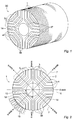
- Figure 1 shows a rotor 30 according to one example, the rotor 30 essentially consisting of a stack of thin rotor discs 1.
- FIG. 2 shows a rotor disc 1 for a rotor 30 according to one embodiment of the invention.
- the depicted rotor disc 1 comprises four pole sectors 15, each pole sector 15 comprising five segments 3 made of a material with a high relative magnetic permeability.
- Each of the five magnetically permeable segments 3 has an arm-shaped form extending between two predetermined angular positions on the disc perimeter 2.
- Four insulating barriers 4 are intermittently disposed between the permeable segments 3 in a manner where an alternating pattern of magnetically permeable segments 3 and insulating barriers 4 are formed along the q-axes 7 of the rotor disc 1 from a central aperture 14 towards the disc perimeter 2.
- the insulating barriers 4 are separated from the air gap 18 between the rotor 30 and the stator 19 by tangential ribs 16.
- the tangential ribs 16 can be left out if the mechanical structure of the rotor disc 1 is ensured by other means.
- the rotor disc 1 is formed as a single unitary element fabricated by punching or stamping a metallic carrier.
- the metallic carrier comprises ferromagnetic metal or alloy with a high relative magnetic permeability.
- the central aperture 14 is shaped to mate to a rotor shaft.
- the insulating barriers 4 are extending between two pitch points 5 at the perimeter 2 of the rotor disc 1.
- the positions of the pitch points 5 have to be accurately defined as they have a great significance for a resulting torque ripple. Since the insulating barriers 4 may get many different shapes and the end portions of the cut-outs often have a rounded shape, it is not always obvious which point exactly should be considered as the pitch point 5.
- a pitch point 5 is a point on the perimeter 2 of the rotor disc 1. In cases where the insulating barrier 4 reaches an air gap 18 between the rotor disc 1 and a surrounding stator 19, the pitch point 5 should be considered to lie in the middle of the opening separating two neighbouring magnetically permeable segments 3.
- the pitch point 5 should be considered to lie on the imaginary continuation of the middle axis of the insulating barrier 4 taking account the overall shape of all the insulating barriers 4. This is often the narrowest point of the tangential ribs 16, but it does not need to be. However, the pitch point 5 is in this case a point on the tangential rib 16, and often this coincides with the narrowest point of the tangential rib 16. In case of a cut-off type of rotor disc 1 with an insulating barrier 4 as the outermost radial portion on the q-axis 7, the outermost insulating barrier 4 is considered not to have pitch points 5.
- Rotor discs 1 are distinguished between two different designs depending on whether the outermost radial portion on a q-axis 7 is a magnetically permeable segment 3 or an insulating barrier 4.
- a rotor disc 1 with a cut-off 11 refers to a rotor type shown in figure 3 wherein the outermost portion of the rotor pole sector 15 comprises an insulating barrier 4, e.g. air in form of a shallow recess provided in the peripheral edge of the rotor perimeter 2.
- the rotor disc 1 is provided with cut-offs 11 in order to disable the magnetic flux at the outermost radial portions on the q-axes 7.
- a rotor disc 1 without a cut-off 11 refers to a rotor type shown in figure 2 wherein the outermost portion of the rotor pole sector 15 consists of a magnetically permeable segment 3 forming a substantially smooth semi-circular perimeter 2.
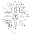
- Figure 4 is a schematic drawing showing the definitions of the reference points 8 and reference angles 9, 10 related to the reference points 8.
- the number of insulating barriers 4 has been chosen to be small (two) for the clarity of the drawing, but any suitable number of barriers can be chosen. However, according to the invention the number of insulating barriers is limited to four.
- the reference points 8 are located on the perimeter 2 of the rotor disc 1 symmetrically with regard the q-axes 7.
- the angular intervals between the reference points 8 define reference angles 9, 10 which between two neighbouring q-axes 7 have an equal value ⁇ m .
- the reference points 8 are marked with circles and crosses, the circles representing real reference points 8 and the crosses representing virtual reference points 8.
- the real reference points 8 are related to the real pitch points 5.
- the virtual reference points 8 are related to pitch points of insulating barriers 4 that for mechanical or other reasons have not been realized. An insulating barrier 4 provided between the virtual reference points 8 would become very small and would have very little significance for the performance of the machine.
- Virtual pitch points are conventionally used to illustrate that the pitch angle is equal even across the q-axes 7 where no actual insulating barriers 4 are present.
- the virtual reference points 8 are used to illustrate, conversely, that the reference angles 10 across the q-axes 7 are different from the reference angles 9 between two neighbouring q-axes 7. Otherwise, the virtual reference points 8 are of no significance for the present invention.
- the optimal ⁇ value normally differs considerably from 3* ⁇ m .
- ⁇ is in theory limited to the angular width of the pole sector 15, but in practice ⁇ must have considerably smaller value such that the insulating barriers 4 obtain reasonable widths and the machine obtains an acceptable torque. According to conducted test cases for a four pole rotor (90 degrees pole sector 15) ⁇ values above 50 degrees are rare.
- the dimensioning of the rotor disc 1 according to the present invention may comprise several iteration steps where different ⁇ values are tested in order to find a value corresponding to a satisfactory or optimal torque ripple behaviour. The testing may be done by using a FEM and a computer simulation.
- the reference points 8 represent the optimal angular positions of the pitch points 5, but small deviations 20 in the angular positions of the pitch points 5 and the corresponding reference points 8 are allowed as denoted by ⁇ ⁇ in figure 4 . Only the angular positions of the two pitch points that are furthest apart between two neighbouring q-axes 7 need to coincide with the angular positions of the corresponding reference points 8, this condition following from the definition of the reference points 8.
- the allowed magnitude ⁇ ⁇ of the deviation 20 represents a tolerance within which a satisfactory torque ripple value is achieved.
- ⁇ ⁇ should have a value less than 3 degrees, preferably less than 2,5 degrees, more preferably less than 2 degrees, and most preferably less than 1 degree.
- the deviation 20 is exaggerated for the purpose of illustration.
- the present invention should preferably be used in combination with an appropriate simulation model which may be configured to return a predetermined performance measure of the rotor disc 1, such as torque ripple, torque, ratio between torque and torque ripple or power factor.
- a predetermined performance measure of the rotor disc 1 such as torque ripple, torque, ratio between torque and torque ripple or power factor.
- one of the design variables of the simulation model is the q-axis pitch angle 12, but the model may comprise a desired number of other design variables as well. Simulation models may differ a lot depending on the general geometry of the rotor cross-section and the shape of the insulating barriers 4. It is assumed that a person skilled in the art is capable of creating a simulation model such as a magnetic representation of a rotor disc 1 in form of a FEM disc model in order to apply the present invention in an effective way.
- the FEM disc model can be created with a commercially available finite element program, for example Flux2D from CEDRAFT Group or Maxwell ® supplied by Ansoft, by entering relevant data defining rotor disc geometry and dimensions, and magnetic and electrical properties of the rotor disc material.
- a commercially available finite element program for example Flux2D from CEDRAFT Group or Maxwell ® supplied by Ansoft, by entering relevant data defining rotor disc geometry and dimensions, and magnetic and electrical properties of the rotor disc material.
- Fig. 5 c) is a graph illustrating an average rotor disc torque 40 and a peak-peak torque ripple 41 in absolute value as a function of the design variable ⁇ for a certain rotor disc model.
- the unit on the ⁇ -axis is Nm (Newton meter) and the unit on the x-axis is degrees.
- the variable 5 is stepped through the discrete set of values 42 indicated by solid dots on the torque ripple curve.
- the two rotor disc portions depicted in Figs. 5 a) and 2 b) illustrate the effect of changing the 5 value to the geometry of a rotor disc 1.
- figure 5 b) represents a ⁇ value of about 31,7 degrees ( ⁇ ⁇ 3,8* ⁇ m ) .
- the torque ripple curve 43 on the graph of Fig. 6 is derived from the data of Fig. 5 c) by computing and displaying the peak-peak torque ripple 41 as a percentage of the average rotor disc torque 40 and mapping the percentage unit on the ⁇ -axis.
- This performance measure is of significant practical interest because it expresses how large a part the torque ripple 41 is of the average torque 40.
- the x-axis shows the ⁇ value in degrees as is the case on Fig. 5 c) .
Landscapes
- Engineering & Computer Science (AREA)
- Power Engineering (AREA)
- Synchronous Machinery (AREA)
- Iron Core Of Rotating Electric Machines (AREA)
Description
- The present invention relates to a rotor for a synchronous reluctance machine, especially the geometry of the insulating barriers of the rotor and the geometry's effect on the torque ripple behaviour of the machine. The present invention further relates to a method of designing a rotor for a synchronous reluctance machine.
- Synchronous reluctance machines known in the art typically comprise stators with poly-phase windings forming a plurality of poles in a manner resembling the stator of an induction motor. The rotor assembly of the synchronous reluctance machine does normally not include electrical windings but has a number of poles in form of magnetically permeable segments. The rotor assembly is formed as an anisotropic structure where each pole of the reluctance machine has a direction of minimum reluctance, a so-called direct axis or d-axis, and a direction of maximum reluctance, a so-called quadrature axis or q-axis. When sinusoidal currents are applied to the poly-phase windings in the stator, an approximately sinusoidal magnetic flux waveform is produced in an air gap formed between the stator poles and an outer contour of the rotor assembly. The rotor will attempt to align its most magnetically permeable direction, the d-axis, to the direction of the peak flux by displacing its d-axis of minimum reluctance until alignment of the magnetic fields in the stator poles and rotor poles is obtained. The alignment process results in rotary motion of the rotor assembly at the same speed as the rotating stator magnetic field, i.e. at synchronous speed. The rotary motion of the rotor generates a torque which can be conveyed to the exterior of the reluctance machine for example by a rotor shaft bonded to the rotor assembly and extending through a central axis thereof.
- According to
figure 1 therotors 30 are given an anisotropic structure by alternating layers of magneticallypermeable segments 3 and magnetically insulatingbarriers 4. The rotor assembly may comprise a stack of transversally oriented rotor laminations or axially oriented rotor laminations. In the case of transversally oriented laminations shown infigure 1 therotor 30 essentially consists of a stack ofthin rotor discs 1 wherein theinsulating barriers 4 are created by cutting material in shape of longitudinal slots. It is thereby the air inside the cut-outs that functions as theinsulating barrier 4. The disc structures are typically designed to be mechanically self-sustained, the magneticallypermeable segments 3 being connected by narrowtangential ribs 16 at the periphery of the discs.Radial ribs 17 close to the middle of the segments are known in order to improve the mechanical strength of the discs. In the case of axially oriented laminations theinsulating barriers 4 are made of some solid insulating material and theinsulating barriers 4 reach the air gap between therotor 30 and the stator. - An important parameter of the rotor is a rotor slot pitch which can be defined as the distance between two adjacent insulating layers measured at the air gap between the rotor and the stator. Rotor assemblies have conventionally been designed with an equal rotor slot pitch i.e. all rotor slot pitches being of equal distance, and an equal stator slot pitch, in order to minimize the torque ripple and to provide a reasonable torque. Another conventional practice has been to set the rotor slot pitch equal to the stator slot pitch.
-
US 5,818,140 discloses a rotor assembly for a synchronous reluctance motor, the structure of the transversely laminated rotor assembly being aimed at minimizing its torque ripple. The disclosed rotor design and the accompanying design formula require an equal rotor slot pitch and an equal stator slot pitch around the respective perimeters of these components. -
US 6,239,526 discloses a rotor assembly for a synchronous reluctance motor, wherein the insulating barriers of the rotor are slanted toward the q-axis. The rotor slot pitch has thereby been rendered non-equal across both q-axis and d-axis, the aim being to minimize the torque ripple by dimensioning the insulating barriers such that while one end faces a centre of a slot of the stator, the other end faces a centre of a tooth of the stator. This disclosure assumes that the rotor slot pitch between the q-axis and the d-axis of each pole is equal to the stator slot pitch. - However, despite the measures taken to decrease the torque ripple, rotors designed according to the conventional design principles still exhibit a high torque ripple.
- Document
US5418415 discloses a device according to the preamble ofclaim 1. - One object of the invention is to provide a rotor for a synchronous reluctance machine, which rotor causes the machine to exhibit a low torque ripple. It is a further object of the invention to provide a method of designing a rotor for a synchronous reluctance machine to obtain a machine exhibiting low torque ripple.
- These objects are achieved by the rotor according to
claim 1. - According to a first aspect of the invention, there is provided a rotor according to
claim 1. - By using the rotor slot pitch across the q-axis (q-axis pitch angle) as a design variable instead of setting its value equal to the rest of the rotor slot pitches or binding its value to the stator slot pitch, an increased design freedom compared to the prior art solutions is achieved which enables the optimization of the torque ripple behaviour of the machine. The present inventors have both experimentally and by finite element method (FEM) simulations demonstrated that selecting a δ value that is different from 3*αm has a significant impact on important performance measures of the rotor disc, in particular the torque ripple. Although it may be difficult to analytically derive the optimal δ value, as soon as all the design variables of a simulating model are set, the optimal q-
axis pitch angle 12 can easily be found in a small number of iteration steps. - The angular positions of the pitch points and the closest reference points may have a deviation having a value Δτ less than 2,5 degrees, such as less than 2 degrees, such as less than 1 degree. Whereas the reference points are representing the optimal angular positions of the pitch points, satisfactory torque ripple behaviour can be achieved even when the angular positions of the pitch points and the corresponding reference point have a small deviation.
- The q-axis pitch angles may differ from 5 = 3*αm by at least 1 degree, such as at least 2, 3, 5 or 10 degrees.
- The rotor may comprise a radial rib across an insulating barrier for improving the mechanical strength of the rotor. The rotor may comprise a cut-off at the rotor perimeter on a q-axis. By providing a rotor disc with an insulating barrier in form of a cut-off at the rotor perimeter the magnetic flux at this outermost radial portion is disabled.
- A simulation model is necessary in order to effectively take advantage of the present invention. When a simulation model comprising a parameter δ for the q-axis pitch angle once is created, it is easy to execute simulations with different δ values in order to find an optimum value.
- The simulation model may be configured to return a value corresponding to the torque ripple. 5 is increased and/or decreased until at least one local minimum of the value corresponding to the torque ripple is found, and the q-axis pitch angle value is determined to correspond to the local minimum of the torque ripple. It is relatively easy to find out the behaviour of the torque ripple curve by a small number of simulations with discrete δ values, and it is logical to give the q-axis pitch angle a value δ that results to a minimum torque ripple.
- The initial value of the q-axis pitch angle may be chosen to be δ = 3*αm. Although the initial q-axis pitch angle value can be chosen arbitrarily, choosing δ = 3*αm is a good starting point and gives an idea how the torque ripple behaviour is improved compared to the prior art solutions.
- The invention will be explained in greater detail with reference to the accompanying drawings, wherein
- figure 1
- shows a rotor according to one example with transversally oriented rotor discs,
- figure 2
- shows a rotor disc without cut-offs,
- figure 3
- shows a rotor disc with cut-offs,
- figure 4
- shows a rotor disc with the definition of reference points and reference angles illustrated,
- figure 5
- shows a simulated torque/torque ripple curve for a certain rotor disc as a function of the q-axis pitch angle, and a corresponding change in the rotor disc geometry, and
- figure 6
- shows a relative torque ripple curve corresponding to the curve of
figure 5 . -
Figure 1 shows arotor 30 according to one example, therotor 30 essentially consisting of a stack ofthin rotor discs 1. -
Figure 2 shows arotor disc 1 for arotor 30 according to one embodiment of the invention. The depictedrotor disc 1 comprises fourpole sectors 15, eachpole sector 15 comprising fivesegments 3 made of a material with a high relative magnetic permeability. Each of the five magneticallypermeable segments 3 has an arm-shaped form extending between two predetermined angular positions on thedisc perimeter 2. Four insulatingbarriers 4 are intermittently disposed between thepermeable segments 3 in a manner where an alternating pattern of magneticallypermeable segments 3 and insulatingbarriers 4 are formed along the q-axes 7 of therotor disc 1 from acentral aperture 14 towards thedisc perimeter 2. The insulatingbarriers 4 are separated from theair gap 18 between therotor 30 and thestator 19 bytangential ribs 16. Optionally thetangential ribs 16 can be left out if the mechanical structure of therotor disc 1 is ensured by other means. Therotor disc 1 is formed as a single unitary element fabricated by punching or stamping a metallic carrier. The metallic carrier comprises ferromagnetic metal or alloy with a high relative magnetic permeability. Thecentral aperture 14 is shaped to mate to a rotor shaft. - The insulating
barriers 4 are extending between twopitch points 5 at theperimeter 2 of therotor disc 1. The positions of the pitch points 5 have to be accurately defined as they have a great significance for a resulting torque ripple. Since the insulatingbarriers 4 may get many different shapes and the end portions of the cut-outs often have a rounded shape, it is not always obvious which point exactly should be considered as thepitch point 5. For the purpose of disclosure, the following definitions are made for the pitch points 5: Apitch point 5 is a point on theperimeter 2 of therotor disc 1. In cases where the insulatingbarrier 4 reaches anair gap 18 between therotor disc 1 and a surroundingstator 19, thepitch point 5 should be considered to lie in the middle of the opening separating two neighbouring magneticallypermeable segments 3. In cases where the insulatingbarriers 4 are separated from theair gap 18 bytangential ribs 16, thepitch point 5 should be considered to lie on the imaginary continuation of the middle axis of the insulatingbarrier 4 taking account the overall shape of all the insulatingbarriers 4. This is often the narrowest point of thetangential ribs 16, but it does not need to be. However, thepitch point 5 is in this case a point on thetangential rib 16, and often this coincides with the narrowest point of thetangential rib 16. In case of a cut-off type ofrotor disc 1 with an insulatingbarrier 4 as the outermost radial portion on the q-axis 7, the outermostinsulating barrier 4 is considered not to have pitch points 5. -
Rotor discs 1 are distinguished between two different designs depending on whether the outermost radial portion on a q-axis 7 is a magneticallypermeable segment 3 or an insulatingbarrier 4. Arotor disc 1 with a cut-off 11 refers to a rotor type shown infigure 3 wherein the outermost portion of therotor pole sector 15 comprises an insulatingbarrier 4, e.g. air in form of a shallow recess provided in the peripheral edge of therotor perimeter 2. Therotor disc 1 is provided with cut-offs 11 in order to disable the magnetic flux at the outermost radial portions on the q-axes 7. Conversely, arotor disc 1 without a cut-off 11 refers to a rotor type shown infigure 2 wherein the outermost portion of therotor pole sector 15 consists of a magneticallypermeable segment 3 forming a substantially smoothsemi-circular perimeter 2. - Since the invention is based on modifications in the insulating barrier geometry which may not be immediately apparent without doing some measurements, we here define some
auxiliary reference points 8 which are useful for explaining the invention and for making the modifications readily measurable.Figure 4 is a schematic drawing showing the definitions of thereference points 8 andreference angles reference points 8. The number ofinsulating barriers 4 has been chosen to be small (two) for the clarity of the drawing, but any suitable number of barriers can be chosen. However, according to the invention the number of insulating barriers is limited to four. - The
reference points 8 are located on theperimeter 2 of therotor disc 1 symmetrically with regard the q-axes 7. The angular intervals between thereference points 8 definereference angles axes 7 have an equal value αm. The value αm is defined by taking the average of the angular distances of the pitch points 5 between two neighbouring q-axes 7, i.e.
angle 13 between twopitch points 5 that are furthest apart between two neighbouring q-axes 7, and k is the number ofpitch points 5 between two neighbouring q-axes 7. - In
figure 4 thereference points 8 are marked with circles and crosses, the circles representingreal reference points 8 and the crosses representingvirtual reference points 8. Thereal reference points 8 are related to the real pitch points 5. Thevirtual reference points 8 are related to pitch points of insulatingbarriers 4 that for mechanical or other reasons have not been realized. An insulatingbarrier 4 provided between thevirtual reference points 8 would become very small and would have very little significance for the performance of the machine. Virtual pitch points are conventionally used to illustrate that the pitch angle is equal even across the q-axes 7 where no actual insulatingbarriers 4 are present. Infigure 4 thevirtual reference points 8 are used to illustrate, conversely, that the reference angles 10 across the q-axes 7 are different from thereference angles 9 between two neighbouring q-axes 7. Otherwise, thevirtual reference points 8 are of no significance for the present invention. - A q-
axis pitch angle 12 is defined by an angular distance between two neighbouring pitch points 5 on opposite sides of a q-axis 7, and is denoted by δ. While in aconventional rotor 30 with an equal rotor slot pitch the q-axis pitch angle 12 becomes δ = 3*αm, according to the present embodiment δ can get an arbitrary value which can be smaller or larger than 3*αm. It may, however, happen that the q-axis pitch angle 12 at which the optimum torque ripple behaviour is achieved lands to a value δ = 3*αm, but this is an exceptional condition and lies outside of the scope of the protection sought. According to a large number of conducted test cases the optimal δ value normally differs considerably from 3*αm. The conducted test cases are showing values for relative difference ηδ
axis pitch angle 12 does not reach the value δ = 0 degrees, since this condition would correspond to removing one of the insulatingbarriers 4. The maximum value of δ is in theory limited to the angular width of thepole sector 15, but in practice δ must have considerably smaller value such that the insulatingbarriers 4 obtain reasonable widths and the machine obtains an acceptable torque. According to conducted test cases for a four pole rotor (90 degrees pole sector 15) δ values above 50 degrees are rare. - The modification of the q-axis pitch angles 12 affects the
reference angles angle 13 between two outermost pitch points 5 between two neighbouring q-axes 7, denoted by γ, is a constant depending on the number of rotor poles. This can be expressed as
rotor disc 1. For a four pole rotor δ+γ = n/2 rad (90 degrees), as can be readily observed fromfigure 4 . By solving γ from equation (3) and substituting in the earlier establishedreference angle 9 definition of equation (1), we can express αm as a function of δ:
- After choosing the δ value all the insulating
barriers 4 are modified accordingly to render the angular positions of the pitch points 5 to correspond to the newly defined αm. The dimensioning of therotor disc 1 according to the present invention may comprise several iteration steps where different δ values are tested in order to find a value corresponding to a satisfactory or optimal torque ripple behaviour. The testing may be done by using a FEM and a computer simulation. - The
reference points 8 represent the optimal angular positions of the pitch points 5, butsmall deviations 20 in the angular positions of the pitch points 5 and thecorresponding reference points 8 are allowed as denoted by Δτ infigure 4 . Only the angular positions of the two pitch points that are furthest apart between two neighbouring q-axes 7 need to coincide with the angular positions of thecorresponding reference points 8, this condition following from the definition of thereference points 8. The allowed magnitude Δτ of thedeviation 20 represents a tolerance within which a satisfactory torque ripple value is achieved. According to simulations made on a number of rotor designs in combination with stators having a various number of slots, Δτ should have a value less than 3 degrees, preferably less than 2,5 degrees, more preferably less than 2 degrees, and most preferably less than 1 degree. Infigure 4 thedeviation 20 is exaggerated for the purpose of illustration. - The present invention should preferably be used in combination with an appropriate simulation model which may be configured to return a predetermined performance measure of the
rotor disc 1, such as torque ripple, torque, ratio between torque and torque ripple or power factor. As can be understood from the earlier description, it is essential for the invention that one of the design variables of the simulation model is the q-axis pitch angle 12, but the model may comprise a desired number of other design variables as well. Simulation models may differ a lot depending on the general geometry of the rotor cross-section and the shape of the insulatingbarriers 4. It is assumed that a person skilled in the art is capable of creating a simulation model such as a magnetic representation of arotor disc 1 in form of a FEM disc model in order to apply the present invention in an effective way. The FEM disc model can be created with a commercially available finite element program, for example Flux2D from CEDRAFT Group or Maxwell® supplied by Ansoft, by entering relevant data defining rotor disc geometry and dimensions, and magnetic and electrical properties of the rotor disc material. - Accordingly, by introducing the new design variable δ in the rotor disc model and changing its value the resulting effect on any desired performance measure of the
rotor disc 1 can be determined. According to the invention, as illustrated infigure 5 c) , selecting the δ value between 30 and 38 degrees (corresponding to δ = 3,5*αm and δ = 5,1*αm, respectively) for a four pole (p=4) and four barrier (k=8) rotor disc design leads to a considerable improvement in the torque ripple without noticeable detrimental effect on the average torque. This insight has lead the inventors to the presently disclosed δ based rotor disc modelling methodologies as a tool for optimizing predetermined performance measures of the rotor disc model. -
Fig. 5 c) is a graph illustrating an averagerotor disc torque 40 and a peak-peak torque ripple 41 in absolute value as a function of the design variable δ for a certain rotor disc model. The unit on the γ-axis is Nm (Newton meter) and the unit on the x-axis is degrees. The variable 5 is stepped through the discrete set ofvalues 42 indicated by solid dots on the torque ripple curve. The two rotor disc portions depicted inFigs. 5 a) and 2 b) illustrate the effect of changing the 5 value to the geometry of arotor disc 1.Figure 5 a) represents a δ value of about 27 degrees corresponding to an equalrotor slot pitch 5 = 3*αm, andfigure 5 b) represents a δ value of about 31,7 degrees (δ ≈ 3,8*αm) . - The depicted torque ripple variation in
Fig. 5 c) at different 5 values clearly demonstrates the significant advantages obtainable by application of the present invention to rotor disc design. For the above-mentioned equal rotor slot pitch condition,torque ripple 41 was computed to about 12,6 Nm while theaverage torque 40 was around 33 Nm. At the local minimum of thetorque ripple 41 with the δ value of around 31,7 degrees, the associatedtorque ripple 41 is considerably reduced to about 4,2 Nm while theaverage torque 40 remains essentially constant with a high value around 33 Nm. - The
torque ripple curve 43 on the graph ofFig. 6 is derived from the data ofFig. 5 c) by computing and displaying the peak-peak torque ripple 41 as a percentage of the averagerotor disc torque 40 and mapping the percentage unit on the γ-axis. This performance measure is of significant practical interest because it expresses how large a part thetorque ripple 41 is of theaverage torque 40. The x-axis shows the δ value in degrees as is the case onFig. 5 c) . Once again, the considerable improvement that can be obtained in the ratio betweentorque ripple 41 andaverage torque 40 by optimizing the δ value is demonstrated. - The invention is not limited to the embodiments described above, but the person skilled in the art may, of course, modify them in a plurality of ways within the scope of the invention as defined by the claims. Whereas in the previous disclosure reference is mostly made to rotor discs, it should be clear for the person skilled in the art that the same design principles can be applied to axially oriented laminations.
Claims (5)
- A rotor (30) for a synchronous reluctance machine, a cross-section of the rotor (30) comprising:four pole sectors (15) arranged symmetrically about a central aperture (14) of the cross-section, each pole sector (15) comprising a plurality of insulating barriers (4),each insulating barrier extending between two pitch points (5),a plurality of q-axes (7), each q-axis (7) defining a direction of maximum reluctance of the corresponding pole sector (15),a perimeter (2) defining the outer contour of the cross-section,a plurality of reference points (8) located on the perimeter (2) symmetrically with regard to the q-axes (7), the angular intervals between the reference points (8) defining reference angles (9, 10) which between two neighbouring q-axes (7) have an equal value of α m = γ/( k -1), where γ is an angle (13) between two pitch points (5) that are furthest apart between two neighbouring q-axes (7) and k is the number of pitch points (5) between two neighbouring q-axes (7),a q-axis pitch angle (12) defined by an angular distance δ between two neighbouring pitch points (5) on opposite sides of a q-axis (7), the q-axis pitch angle (12) having a value which is different from δ = 3*αm,the angular positions of each pitch point (5) and the reference point (8) closest to that pitch point (5) have a deviation (20) having a value Δτ less than 2,5 degrees,characterized in thatthe q-axis pitch angle (12) has a value δ between 30 and 38 degrees, and in that k=8.
- A rotor (30) according to claim 1, wherein the angular positions of the pitch points (5) and the closest reference points (8) have a deviation (20) having a value Δτ less than 2 degrees, such as less than 1 degree.
- A rotor (30) according to claim 1 or 2, wherein the q-axis pitch angles (12) differ from δ = 3*αm by at least 1 degree, such as at least 2, 3, 5 or 10 degrees.
- A rotor (30) according to any of the preceding claims comprising a radial rib (17) across an insulating barrier (4) for improving the mechanical strength of the rotor (30).
- A rotor (30) according to any of the preceding claims comprising a cut-off (11) at the rotor perimeter (2) on a q-axis (7).
Priority Applications (1)
| Application Number | Priority Date | Filing Date | Title |
|---|---|---|---|
| EP16159440.3A EP3086450B1 (en) | 2009-03-12 | 2009-03-12 | Rotor for a synchronous reluctance machine |
Applications Claiming Priority (1)
| Application Number | Priority Date | Filing Date | Title |
|---|---|---|---|
| PCT/EP2009/052930 WO2010102671A1 (en) | 2009-03-12 | 2009-03-12 | Rotor for a synchronous reluctance machine |
Related Child Applications (2)
| Application Number | Title | Priority Date | Filing Date |
|---|---|---|---|
| EP16159440.3A Division-Into EP3086450B1 (en) | 2009-03-12 | 2009-03-12 | Rotor for a synchronous reluctance machine |
| EP16159440.3A Division EP3086450B1 (en) | 2009-03-12 | 2009-03-12 | Rotor for a synchronous reluctance machine |
Publications (2)
| Publication Number | Publication Date |
|---|---|
| EP2406870A1 EP2406870A1 (en) | 2012-01-18 |
| EP2406870B1 true EP2406870B1 (en) | 2016-05-11 |
Family
ID=41396503
Family Applications (2)
| Application Number | Title | Priority Date | Filing Date |
|---|---|---|---|
| EP16159440.3A Active EP3086450B1 (en) | 2009-03-12 | 2009-03-12 | Rotor for a synchronous reluctance machine |
| EP09779141.2A Revoked EP2406870B1 (en) | 2009-03-12 | 2009-03-12 | Rotor for a synchronous reluctance machine |
Family Applications Before (1)
| Application Number | Title | Priority Date | Filing Date |
|---|---|---|---|
| EP16159440.3A Active EP3086450B1 (en) | 2009-03-12 | 2009-03-12 | Rotor for a synchronous reluctance machine |
Country Status (7)
| Country | Link |
|---|---|
| US (2) | US8638012B2 (en) |
| EP (2) | EP3086450B1 (en) |
| JP (1) | JP5726768B2 (en) |
| KR (1) | KR101270898B1 (en) |
| CN (1) | CN102349220B (en) |
| BR (1) | BRPI0924419B1 (en) |
| WO (1) | WO2010102671A1 (en) |
Cited By (1)
| Publication number | Priority date | Publication date | Assignee | Title |
|---|---|---|---|---|
| EP4250536A1 (en) | 2022-03-25 | 2023-09-27 | Deeper Pulse | Rotors, reluctance machines, systems and manufacturing methods for rotors |
Families Citing this family (22)
| Publication number | Priority date | Publication date | Assignee | Title |
|---|---|---|---|---|
| CN102349220B (en) | 2009-03-12 | 2017-09-19 | Abb研究有限公司 | Rotor for synchronous magnetic resistance motor |
| IT1403055B1 (en) * | 2010-11-30 | 2013-09-27 | Itaco S R L Ora Reel S R L | ELECTRIC GENERATOR. |
| JP6366986B2 (en) * | 2014-04-11 | 2018-08-01 | 株式会社東芝 | Synchronous reluctance rotary electric machine |
| GB2529604B (en) | 2014-05-23 | 2017-02-22 | Technelec Ltd | Synchronous reluctance machine |
| DE102014215304A1 (en) * | 2014-08-04 | 2016-02-04 | Ksb Aktiengesellschaft | Rotor, reluctance machine and rotor manufacturing method |
| ES2784177T3 (en) * | 2014-08-05 | 2020-09-22 | Ego Elektro Geraetebau Gmbh | Household appliance |
| WO2016139991A1 (en) * | 2015-03-03 | 2016-09-09 | 三菱電機株式会社 | Reluctance motor, and method for manufacturing rotor core used in reluctance motor |
| DE102015215585A1 (en) * | 2015-08-14 | 2017-02-16 | Ksb Aktiengesellschaft | Rotor package for a synchronous reluctance machine |
| US10491061B2 (en) * | 2015-12-08 | 2019-11-26 | General Electric Company | Rotor for a reluctance machine |
| EP3185400B1 (en) * | 2015-12-21 | 2022-03-16 | JULI Motorenwerk, s.r.o. | Rotor for a synchronous reluctance motor |
| CN105490495B (en) * | 2016-01-26 | 2019-10-25 | 珠海格力电器股份有限公司 | Motor rotor and motor with same |
| CN105553139B (en) | 2016-01-26 | 2017-12-12 | 珠海格力节能环保制冷技术研究中心有限公司 | A kind of synchronous magnetic resistance motor rotor and synchronous magnetic resistance motor |
| JP6571050B2 (en) * | 2016-06-29 | 2019-09-04 | 株式会社東芝 | Synchronous reluctance rotary electric machine |
| EP3264569B1 (en) * | 2016-07-01 | 2019-12-04 | ABB Schweiz AG | Rotor for a synchronous reluctance electric machine, an electric machine, and a manufacturing method of a rotor |
| RU2634587C1 (en) | 2016-07-26 | 2017-11-01 | Общество с ограниченной ответственностью "ЭМАШ" | Synchronous reluctance machine |
| TWI593214B (en) * | 2016-12-28 | 2017-07-21 | 東元電機股份有限公司 | Rotor structure of synchronous reluctance motor |
| US10673311B2 (en) | 2017-08-22 | 2020-06-02 | Abb Schweiz Ag | Electric motor with low torque ripple |
| RU2669361C1 (en) | 2017-11-13 | 2018-10-11 | Ооо "Эмаш" | Synchronous reactive machine |
| CN109861414A (en) * | 2017-11-30 | 2019-06-07 | 日本电产株式会社 | Rotor, motor and the electrical equipment comprising the motor |
| EP3742583A1 (en) * | 2019-05-22 | 2020-11-25 | Siemens Aktiengesellschaft | Quadrupole synchronous reluctance machine |
| CN110212724B (en) * | 2019-06-19 | 2023-12-08 | 珠海格力电器股份有限公司 | Self-starting synchronous reluctance motor and compressor with same |
| CN113315437B (en) * | 2021-06-09 | 2024-03-15 | 河北工业大学 | Synchronous reluctance motor rotor shape optimization method and a synchronous reluctance motor |
Citations (8)
| Publication number | Priority date | Publication date | Assignee | Title |
|---|---|---|---|---|
| US4924130A (en) | 1988-04-21 | 1990-05-08 | Antonino Fratta | Reluctance synchronous electric machine having intrinsic phase correction means |
| US5418415A (en) | 1993-03-04 | 1995-05-23 | Ishizaki; Akira | Reluctance motor and generator |
| JPH07303357A (en) | 1994-05-02 | 1995-11-14 | Okuma Mach Works Ltd | Synchronous motor |
| US5818140A (en) | 1995-07-11 | 1998-10-06 | Vagati; Alfredo | Synchronous reluctance electrical motor having a low torque-ripple design |
| JP2000197325A (en) | 1998-12-25 | 2000-07-14 | Matsushita Electric Ind Co Ltd | Reluctance motor |
| DE10004175A1 (en) | 1999-09-22 | 2001-04-05 | Lg Electronics Inc | Synchronous reluctance motor has magnetic flux barriers in rotor with ribs forming end section of individual magnetic flux barriers, except both ends of one are formed by separate ribs |
| JP2001136717A (en) | 1999-11-04 | 2001-05-18 | Okuma Corp | Reluctance motor |
| WO2010102671A1 (en) | 2009-03-12 | 2010-09-16 | Abb Research Ltd | Rotor for a synchronous reluctance machine |
Family Cites Families (5)
| Publication number | Priority date | Publication date | Assignee | Title |
|---|---|---|---|---|
| GB2310544B (en) * | 1996-02-21 | 2000-03-29 | Switched Reluctance Drives Ltd | Method of forming a rotor for a reluctance machine |
| JP3051340B2 (en) * | 1996-06-18 | 2000-06-12 | オークマ株式会社 | Synchronous motor |
| JP3428896B2 (en) * | 1998-05-07 | 2003-07-22 | オークマ株式会社 | Motor with reduced torque ripple |
| JP2001095182A (en) * | 1999-09-20 | 2001-04-06 | Fujitsu General Ltd | Permanent magnet motor |
| JP2001258222A (en) * | 2000-03-10 | 2001-09-21 | Mitsubishi Electric Corp | Reluctance motor |
-
2009
- 2009-03-12 CN CN200980158067.5A patent/CN102349220B/en active Active
- 2009-03-12 JP JP2011553291A patent/JP5726768B2/en active Active
- 2009-03-12 EP EP16159440.3A patent/EP3086450B1/en active Active
- 2009-03-12 WO PCT/EP2009/052930 patent/WO2010102671A1/en not_active Ceased
- 2009-03-12 EP EP09779141.2A patent/EP2406870B1/en not_active Revoked
- 2009-03-12 BR BRPI0924419A patent/BRPI0924419B1/en active IP Right Grant
- 2009-03-12 KR KR1020117023777A patent/KR101270898B1/en active Active
-
2011
- 2011-09-12 US US13/230,543 patent/US8638012B2/en active Active
-
2016
- 2016-08-16 US US15/238,159 patent/USRE46867E1/en active Active
Patent Citations (8)
| Publication number | Priority date | Publication date | Assignee | Title |
|---|---|---|---|---|
| US4924130A (en) | 1988-04-21 | 1990-05-08 | Antonino Fratta | Reluctance synchronous electric machine having intrinsic phase correction means |
| US5418415A (en) | 1993-03-04 | 1995-05-23 | Ishizaki; Akira | Reluctance motor and generator |
| JPH07303357A (en) | 1994-05-02 | 1995-11-14 | Okuma Mach Works Ltd | Synchronous motor |
| US5818140A (en) | 1995-07-11 | 1998-10-06 | Vagati; Alfredo | Synchronous reluctance electrical motor having a low torque-ripple design |
| JP2000197325A (en) | 1998-12-25 | 2000-07-14 | Matsushita Electric Ind Co Ltd | Reluctance motor |
| DE10004175A1 (en) | 1999-09-22 | 2001-04-05 | Lg Electronics Inc | Synchronous reluctance motor has magnetic flux barriers in rotor with ribs forming end section of individual magnetic flux barriers, except both ends of one are formed by separate ribs |
| JP2001136717A (en) | 1999-11-04 | 2001-05-18 | Okuma Corp | Reluctance motor |
| WO2010102671A1 (en) | 2009-03-12 | 2010-09-16 | Abb Research Ltd | Rotor for a synchronous reluctance machine |
Non-Patent Citations (9)
| Title |
|---|
| A. VAGATI ET AL.: "DESIGN OF LOW-TORQUE-RIPPLE SYNCHRONOUS RELUCTANCE MOTORS", IAS '97. CONFERENCE RECORD OF THE 1997 IEEE INDUSTRY APPLICATIONS CONFERENCE 32ND. IAS ANNUAL MEETING, October 1997 (1997-10-01), NEW ORLEANS, LA, pages 286 - 293, XP000775189 |
| A. VAGATI ET AL.: "Design of Low-Torque-Ripple Synchronous Reluctance Motors", PROCEEDINGS OF ANNUAL MEETING, 5 October 1997 (1997-10-05), New Orleans, Louisiana, pages 286 - 293, XP000775189 |
| BOMELA ET AL.: "Effect of machine design on performance of reluctance synchronous machine", INDUSTRY APPLICATIONS CONFERENCE, 2000. CONFERENCE RECORD OF THE 2000 IEEE, October 2000 (2000-10-01), pages 515 - 522, XP010521257 |
| J. HAATAJA: "A Comparative Performance Study of Four-Pole Induction Motors and Synchronous Reluctance Motors In Variable Speed Drives", DOCTORAL THESIS, June 2003 (2003-06-01), Lappeenranta, Finland, XP055355285, ISSN: 1456-4491, ISBN: 951-764-772-7 |
| J. J. GERMISHUIZEN ET AL.: "Performance Comparison of Reluctance Synchronous and Induction Traction Drives for Electrical Multiple Units", PROCEEDINGS OF THE INDUSTRY APPLICATIONS CONFERENCE, 8 October 2000 (2000-10-08), pages 316 - 323, XP010521228 |
| VAGATI A.;: "Cross-Saturation Effects in IPM Motors and Related Impact on Sensorless Control.", IEEE TRANSACTIONS ON INDUSTRY APPLICATIONS, vol. 42, no. 6, 2006, pages 1516 - 1522., XP011142957, ISSN: 0093-9994 |
| X. B. BOMELA: "Some Design Aspects of the Multi Flux Barrier Rotor Reluctance Synchronous Machine", MASTER THESIS, December 2000 (2000-12-01), South Africa, XP055355278 |
| X.B. BOMELA ET AL.: "Effect of Stator Chording and Rotor Skewing on Performance of Reluctance Synchronous Machine", IEEE TRANSACTIONS ON INDUSTRY APPLICATIONS, vol. 38, no. 1, January 2002 (2002-01-01), pages 91 - 100, XP055355286 |
| X.B. BOMELA ET AL.: "Performance of Small and Medium Power Flux Barrier Rotor Reluctance Synchronous Machine Drives", INTERNATIONAL CONFERENCE ON ELECTRICAL MACHINES; ICEM '98 PROCEEDINGS, 1998, pages 95 - 99, XP055355283, Retrieved from the Internet <URL:http://icem.metu.edu.tr/contents98p1d.htm> |
Cited By (2)
| Publication number | Priority date | Publication date | Assignee | Title |
|---|---|---|---|---|
| EP4250536A1 (en) | 2022-03-25 | 2023-09-27 | Deeper Pulse | Rotors, reluctance machines, systems and manufacturing methods for rotors |
| WO2023180574A1 (en) | 2022-03-25 | 2023-09-28 | Deeper Pulse | Rotors, reluctance machines, systems and manufacturing methods for rotors |
Also Published As
| Publication number | Publication date |
|---|---|
| CN102349220A (en) | 2012-02-08 |
| US20120062053A1 (en) | 2012-03-15 |
| BRPI0924419A2 (en) | 2016-01-26 |
| EP2406870A1 (en) | 2012-01-18 |
| WO2010102671A1 (en) | 2010-09-16 |
| USRE46867E1 (en) | 2018-05-22 |
| BRPI0924419A8 (en) | 2017-09-26 |
| BRPI0924419B1 (en) | 2020-04-07 |
| US8638012B2 (en) | 2014-01-28 |
| KR101270898B1 (en) | 2013-06-07 |
| EP3086450B1 (en) | 2023-06-07 |
| JP2012520055A (en) | 2012-08-30 |
| KR20110138365A (en) | 2011-12-27 |
| JP5726768B2 (en) | 2015-06-03 |
| EP3086450C0 (en) | 2023-06-07 |
| CN102349220B (en) | 2017-09-19 |
| EP3086450A1 (en) | 2016-10-26 |
Similar Documents
| Publication | Publication Date | Title |
|---|---|---|
| EP3086450B1 (en) | Rotor for a synchronous reluctance machine | |
| Howard et al. | Asymmetric flux barrier and skew design optimization of reluctance synchronous machines | |
| US7973442B2 (en) | Permanent magnet-type rotary electric machine and production method for rotor for permanent magnet-type rotary electric machine | |
| EP2442432B1 (en) | Rotor of a synchronous reluctance machine and the method for manufacturing the rotor of a synchronous reluctance machine | |
| Ionel et al. | Ultrafast finite-element analysis of brushless PM machines based on space–time transformations | |
| KR102084999B1 (en) | Rotor for electric machine and manufacturing method of rotor | |
| de Paula et al. | On-load back EMF of PMSM using Maxwell stress tensor | |
| CN101478210A (en) | Asymmetric groove shaped permanent synchronizing motor | |
| JP2021016205A (en) | Synchronous reluctance motor | |
| EP3334017A1 (en) | Synchronous reluctance machine | |
| Tsunata et al. | Skewing technology for permanent magnet synchronous motors: A comprehensive review and recent trends | |
| JP7101869B2 (en) | Synchronous reluctance motor | |
| WO2004064226A1 (en) | Method for controlling electric motor cogging and permanent magnet electric motor | |
| US20240283310A1 (en) | Rotor and rotating electric machine | |
| Darmani et al. | Multiphysics sizing of interior permanent magnet machines based on geometric methodology | |
| JP5839298B2 (en) | motor | |
| Rostami et al. | Analysis of AFPM machines with cylindrically shaped magnets using quasi-3D method | |
| Hombitzer et al. | Performance improvement of a high-speed permanent magnet excited synchronous machine by flux-barrier design | |
| Mahmoudi et al. | Introduction of Double-Stator Synchronous Reluctance Motor and Modeling | |
| Pečínka et al. | Use of FEM modeling to optimize the design of induction motor | |
| Akbar et al. | Enhanced Design and Electromagnetic Analysis of Synchronous Reluctance Machines Using Multi-Material Additive Manufacturing | |
| Tang et al. | Analysis of stator iron loss in interior PM machines under open and short-circuit conditions | |
| Sengamalai et al. | Optimisation of interior permanent magnet rotors for charging electric vehicle batteries with integration of electromagnetic and mechanical design | |
| Wilfling et al. | Segmented exterior-rotor PMSM for increased torque density | |
| Notz | Utilising the axial degree of freedom in the design of an additively manufactured rotor of a synchronous reluctance machine |
Legal Events
| Date | Code | Title | Description |
|---|---|---|---|
| PUAI | Public reference made under article 153(3) epc to a published international application that has entered the european phase |
Free format text: ORIGINAL CODE: 0009012 |
|
| 17P | Request for examination filed |
Effective date: 20111012 |
|
| AK | Designated contracting states |
Kind code of ref document: A1 Designated state(s): AT BE BG CH CY CZ DE DK EE ES FI FR GB GR HR HU IE IS IT LI LT LU LV MC MK MT NL NO PL PT RO SE SI SK TR |
|
| DAX | Request for extension of the european patent (deleted) | ||
| 17Q | First examination report despatched |
Effective date: 20131121 |
|
| GRAP | Despatch of communication of intention to grant a patent |
Free format text: ORIGINAL CODE: EPIDOSNIGR1 |
|
| INTG | Intention to grant announced |
Effective date: 20151216 |
|
| GRAS | Grant fee paid |
Free format text: ORIGINAL CODE: EPIDOSNIGR3 |
|
| GRAA | (expected) grant |
Free format text: ORIGINAL CODE: 0009210 |
|
| AK | Designated contracting states |
Kind code of ref document: B1 Designated state(s): AT BE BG CH CY CZ DE DK EE ES FI FR GB GR HR HU IE IS IT LI LT LU LV MC MK MT NL NO PL PT RO SE SI SK TR |
|
| REG | Reference to a national code |
Ref country code: GB Ref legal event code: FG4D |
|
| REG | Reference to a national code |
Ref country code: CH Ref legal event code: EP |
|
| REG | Reference to a national code |
Ref country code: AT Ref legal event code: REF Ref document number: 799361 Country of ref document: AT Kind code of ref document: T Effective date: 20160515 |
|
| REG | Reference to a national code |
Ref country code: IE Ref legal event code: FG4D |
|
| REG | Reference to a national code |
Ref country code: DE Ref legal event code: R096 Ref document number: 602009038632 Country of ref document: DE |
|
| REG | Reference to a national code |
Ref country code: LT Ref legal event code: MG4D |
|
| REG | Reference to a national code |
Ref country code: NL Ref legal event code: MP Effective date: 20160511 |
|
| PG25 | Lapsed in a contracting state [announced via postgrant information from national office to epo] |
Ref country code: NO Free format text: LAPSE BECAUSE OF FAILURE TO SUBMIT A TRANSLATION OF THE DESCRIPTION OR TO PAY THE FEE WITHIN THE PRESCRIBED TIME-LIMIT Effective date: 20160811 Ref country code: FI Free format text: LAPSE BECAUSE OF FAILURE TO SUBMIT A TRANSLATION OF THE DESCRIPTION OR TO PAY THE FEE WITHIN THE PRESCRIBED TIME-LIMIT Effective date: 20160511 Ref country code: NL Free format text: LAPSE BECAUSE OF FAILURE TO SUBMIT A TRANSLATION OF THE DESCRIPTION OR TO PAY THE FEE WITHIN THE PRESCRIBED TIME-LIMIT Effective date: 20160511 Ref country code: LT Free format text: LAPSE BECAUSE OF FAILURE TO SUBMIT A TRANSLATION OF THE DESCRIPTION OR TO PAY THE FEE WITHIN THE PRESCRIBED TIME-LIMIT Effective date: 20160511 |
|
| PG25 | Lapsed in a contracting state [announced via postgrant information from national office to epo] |
Ref country code: SE Free format text: LAPSE BECAUSE OF FAILURE TO SUBMIT A TRANSLATION OF THE DESCRIPTION OR TO PAY THE FEE WITHIN THE PRESCRIBED TIME-LIMIT Effective date: 20160511 Ref country code: PT Free format text: LAPSE BECAUSE OF FAILURE TO SUBMIT A TRANSLATION OF THE DESCRIPTION OR TO PAY THE FEE WITHIN THE PRESCRIBED TIME-LIMIT Effective date: 20160912 Ref country code: LV Free format text: LAPSE BECAUSE OF FAILURE TO SUBMIT A TRANSLATION OF THE DESCRIPTION OR TO PAY THE FEE WITHIN THE PRESCRIBED TIME-LIMIT Effective date: 20160511 Ref country code: GR Free format text: LAPSE BECAUSE OF FAILURE TO SUBMIT A TRANSLATION OF THE DESCRIPTION OR TO PAY THE FEE WITHIN THE PRESCRIBED TIME-LIMIT Effective date: 20160812 Ref country code: ES Free format text: LAPSE BECAUSE OF FAILURE TO SUBMIT A TRANSLATION OF THE DESCRIPTION OR TO PAY THE FEE WITHIN THE PRESCRIBED TIME-LIMIT Effective date: 20160511 Ref country code: HR Free format text: LAPSE BECAUSE OF FAILURE TO SUBMIT A TRANSLATION OF THE DESCRIPTION OR TO PAY THE FEE WITHIN THE PRESCRIBED TIME-LIMIT Effective date: 20160511 |
|
| PG25 | Lapsed in a contracting state [announced via postgrant information from national office to epo] |
Ref country code: EE Free format text: LAPSE BECAUSE OF FAILURE TO SUBMIT A TRANSLATION OF THE DESCRIPTION OR TO PAY THE FEE WITHIN THE PRESCRIBED TIME-LIMIT Effective date: 20160511 Ref country code: RO Free format text: LAPSE BECAUSE OF FAILURE TO SUBMIT A TRANSLATION OF THE DESCRIPTION OR TO PAY THE FEE WITHIN THE PRESCRIBED TIME-LIMIT Effective date: 20160511 Ref country code: DK Free format text: LAPSE BECAUSE OF FAILURE TO SUBMIT A TRANSLATION OF THE DESCRIPTION OR TO PAY THE FEE WITHIN THE PRESCRIBED TIME-LIMIT Effective date: 20160511 Ref country code: SK Free format text: LAPSE BECAUSE OF FAILURE TO SUBMIT A TRANSLATION OF THE DESCRIPTION OR TO PAY THE FEE WITHIN THE PRESCRIBED TIME-LIMIT Effective date: 20160511 |
|
| REG | Reference to a national code |
Ref country code: DE Ref legal event code: R026 Ref document number: 602009038632 Country of ref document: DE |
|
| PLBI | Opposition filed |
Free format text: ORIGINAL CODE: 0009260 |
|
| PG25 | Lapsed in a contracting state [announced via postgrant information from national office to epo] |
Ref country code: BE Free format text: LAPSE BECAUSE OF FAILURE TO SUBMIT A TRANSLATION OF THE DESCRIPTION OR TO PAY THE FEE WITHIN THE PRESCRIBED TIME-LIMIT Effective date: 20160511 Ref country code: PL Free format text: LAPSE BECAUSE OF FAILURE TO SUBMIT A TRANSLATION OF THE DESCRIPTION OR TO PAY THE FEE WITHIN THE PRESCRIBED TIME-LIMIT Effective date: 20160511 |
|
| PLAX | Notice of opposition and request to file observation + time limit sent |
Free format text: ORIGINAL CODE: EPIDOSNOBS2 |
|
| 26 | Opposition filed |
Opponent name: LINDE MATERIAL HANDLING GMBH Effective date: 20170210 Opponent name: JUNGHEINRICH AKTIENGESELLSCHAFT Effective date: 20170209 Opponent name: KSB AKTIENGESELLSCHAFT Effective date: 20170208 |
|
| REG | Reference to a national code |
Ref country code: FR Ref legal event code: PLFP Year of fee payment: 9 |
|
| PG25 | Lapsed in a contracting state [announced via postgrant information from national office to epo] |
Ref country code: SI Free format text: LAPSE BECAUSE OF FAILURE TO SUBMIT A TRANSLATION OF THE DESCRIPTION OR TO PAY THE FEE WITHIN THE PRESCRIBED TIME-LIMIT Effective date: 20160511 |
|
| PLBB | Reply of patent proprietor to notice(s) of opposition received |
Free format text: ORIGINAL CODE: EPIDOSNOBS3 |
|
| PG25 | Lapsed in a contracting state [announced via postgrant information from national office to epo] |
Ref country code: MC Free format text: LAPSE BECAUSE OF FAILURE TO SUBMIT A TRANSLATION OF THE DESCRIPTION OR TO PAY THE FEE WITHIN THE PRESCRIBED TIME-LIMIT Effective date: 20160511 |
|
| REG | Reference to a national code |
Ref country code: IE Ref legal event code: MM4A |
|
| PG25 | Lapsed in a contracting state [announced via postgrant information from national office to epo] |
Ref country code: LU Free format text: LAPSE BECAUSE OF NON-PAYMENT OF DUE FEES Effective date: 20170312 |
|
| PG25 | Lapsed in a contracting state [announced via postgrant information from national office to epo] |
Ref country code: IE Free format text: LAPSE BECAUSE OF NON-PAYMENT OF DUE FEES Effective date: 20170312 |
|
| REG | Reference to a national code |
Ref country code: AT Ref legal event code: UEP Ref document number: 799361 Country of ref document: AT Kind code of ref document: T Effective date: 20160511 |
|
| REG | Reference to a national code |
Ref country code: FR Ref legal event code: PLFP Year of fee payment: 10 |
|
| PGFP | Annual fee paid to national office [announced via postgrant information from national office to epo] |
Ref country code: GB Payment date: 20180321 Year of fee payment: 10 Ref country code: CH Payment date: 20180321 Year of fee payment: 10 Ref country code: DE Payment date: 20180322 Year of fee payment: 10 Ref country code: CZ Payment date: 20180309 Year of fee payment: 10 |
|
| PGFP | Annual fee paid to national office [announced via postgrant information from national office to epo] |
Ref country code: AT Payment date: 20180322 Year of fee payment: 10 Ref country code: TR Payment date: 20180312 Year of fee payment: 10 Ref country code: FR Payment date: 20180328 Year of fee payment: 10 |
|
| REG | Reference to a national code |
Ref country code: DE Ref legal event code: R064 Ref document number: 602009038632 Country of ref document: DE Ref country code: DE Ref legal event code: R103 Ref document number: 602009038632 Country of ref document: DE |
|
| RDAF | Communication despatched that patent is revoked |
Free format text: ORIGINAL CODE: EPIDOSNREV1 |
|
| STAA | Information on the status of an ep patent application or granted ep patent |
Free format text: STATUS: THE PATENT HAS BEEN GRANTED |
|
| PGFP | Annual fee paid to national office [announced via postgrant information from national office to epo] |
Ref country code: IT Payment date: 20180327 Year of fee payment: 10 |
|
| PG25 | Lapsed in a contracting state [announced via postgrant information from national office to epo] |
Ref country code: MT Free format text: LAPSE BECAUSE OF NON-PAYMENT OF DUE FEES Effective date: 20170312 |
|
| RDAG | Patent revoked |
Free format text: ORIGINAL CODE: 0009271 |
|
| STAA | Information on the status of an ep patent application or granted ep patent |
Free format text: STATUS: PATENT REVOKED |
|
| REG | Reference to a national code |
Ref country code: CH Ref legal event code: PL |
|
| 27W | Patent revoked |
Effective date: 20180625 |
|
| GBPR | Gb: patent revoked under art. 102 of the ep convention designating the uk as contracting state |
Effective date: 20180625 |
|
| REG | Reference to a national code |
Ref country code: AT Ref legal event code: MA03 Ref document number: 799361 Country of ref document: AT Kind code of ref document: T Effective date: 20180625 |
|
| PG25 | Lapsed in a contracting state [announced via postgrant information from national office to epo] |
Ref country code: BG Free format text: LAPSE BECAUSE OF FAILURE TO SUBMIT A TRANSLATION OF THE DESCRIPTION OR TO PAY THE FEE WITHIN THE PRESCRIBED TIME-LIMIT Effective date: 20160511 |
|
| PG25 | Lapsed in a contracting state [announced via postgrant information from national office to epo] |
Ref country code: MK Free format text: LAPSE BECAUSE OF FAILURE TO SUBMIT A TRANSLATION OF THE DESCRIPTION OR TO PAY THE FEE WITHIN THE PRESCRIBED TIME-LIMIT Effective date: 20160511 |
|
| PG25 | Lapsed in a contracting state [announced via postgrant information from national office to epo] |
Ref country code: CY Free format text: LAPSE BECAUSE OF FAILURE TO SUBMIT A TRANSLATION OF THE DESCRIPTION OR TO PAY THE FEE WITHIN THE PRESCRIBED TIME-LIMIT Effective date: 20160511 |
|
| PG25 | Lapsed in a contracting state [announced via postgrant information from national office to epo] |
Ref country code: IS Free format text: LAPSE BECAUSE OF FAILURE TO SUBMIT A TRANSLATION OF THE DESCRIPTION OR TO PAY THE FEE WITHIN THE PRESCRIBED TIME-LIMIT Effective date: 20160911 |