EP2406042B1 - Shaving device with improved contour following - Google Patents
Shaving device with improved contour following Download PDFInfo
- Publication number
- EP2406042B1 EP2406042B1 EP20100708630 EP10708630A EP2406042B1 EP 2406042 B1 EP2406042 B1 EP 2406042B1 EP 20100708630 EP20100708630 EP 20100708630 EP 10708630 A EP10708630 A EP 10708630A EP 2406042 B1 EP2406042 B1 EP 2406042B1
- Authority
- EP
- European Patent Office
- Prior art keywords
- cutting
- suspension
- shaving
- pivot construction
- pivot
- Prior art date
- Legal status (The legal status is an assumption and is not a legal conclusion. Google has not performed a legal analysis and makes no representation as to the accuracy of the status listed.)
- Active
Links
Images

Classifications
-
- B—PERFORMING OPERATIONS; TRANSPORTING
- B26—HAND CUTTING TOOLS; CUTTING; SEVERING
- B26B—HAND-HELD CUTTING TOOLS NOT OTHERWISE PROVIDED FOR
- B26B19/00—Clippers or shavers operating with a plurality of cutting edges, e.g. hair clippers, dry shavers
- B26B19/14—Clippers or shavers operating with a plurality of cutting edges, e.g. hair clippers, dry shavers of the rotary-cutter type; Cutting heads therefor; Cutters therefor
- B26B19/143—Details of outer cutters
-
- B—PERFORMING OPERATIONS; TRANSPORTING
- B26—HAND CUTTING TOOLS; CUTTING; SEVERING
- B26B—HAND-HELD CUTTING TOOLS NOT OTHERWISE PROVIDED FOR
- B26B19/00—Clippers or shavers operating with a plurality of cutting edges, e.g. hair clippers, dry shavers
- B26B19/14—Clippers or shavers operating with a plurality of cutting edges, e.g. hair clippers, dry shavers of the rotary-cutter type; Cutting heads therefor; Cutters therefor
- B26B19/145—Cutters being movable in the cutting head
-
- B—PERFORMING OPERATIONS; TRANSPORTING
- B26—HAND CUTTING TOOLS; CUTTING; SEVERING
- B26B—HAND-HELD CUTTING TOOLS NOT OTHERWISE PROVIDED FOR
- B26B19/00—Clippers or shavers operating with a plurality of cutting edges, e.g. hair clippers, dry shavers
- B26B19/14—Clippers or shavers operating with a plurality of cutting edges, e.g. hair clippers, dry shavers of the rotary-cutter type; Cutting heads therefor; Cutters therefor
- B26B19/146—Complete cutting head being movable
Definitions
- the present invention relates to a shaving head for use in a shaving device for removing hairs from skin by cutting through the hairs, comprising at least one cutting unit, and a holder for holding the cutting unit, which holder is intended to be mounted on a body portion of the shaving device, which body portion is intended to be taken hold of by a user of the shaving device, and serves for accommodating various members of the shaving device, wherein the cutting unit comprises an external cutting member having a surface which is intended for contacting skin during a shaving action, and which is interrupted by openings for allowing hairs to pass, wherein the cutting unit further comprises an internal cutting member which is drivable for movement along the openings in the surface of the external cutting member, and which is adapted to cut through hairs during such movement, wherein the external cutting member is suspended relative to the holder through suspension means comprising:
- the present invention relates to a shaving device for removing hairs from skin by cutting through the hairs, comprising a body portion which is intended to be taken hold of by a user of the shaving device, and which serves for accommodating various members of the shaving device, and a shaving head as mentioned.
- a shaving device comprising a body portion, and a shaving head having at least one cutting unit and a holder as described above is known from WO 2006/067721 .
- the shaving device is a so-called rotary shaving device, i.e. a shaving device in which the internal cutting member comprises a ring-shaped support portion which is provided with a number of cutting blades, wherein the support portion is driven such as to rotate during operation of the shaving device.
- the shaving head of the shaving device is equipped with three cutting units.
- the external cutting member of the cutting units is shaped like a cap which serves for covering the internal cutting member, which is intended to be used for contacting portions of skin to be subjected to a shaving action, and which is provided with openings for letting through hairs from the portions of skin to the cutting blades of the internal cutting member. It is understood that a main function of the external cutting member is avoiding direct contact between the cutting blades of the internal cutting member and the portions of skin, so that skin damage is prevented.
- the shaving device comprises means such as a motor for driving the internal cutting members.
- Proper use of the shaving device involves movement of the shaving device in such a way that a surface of the external cutting members glides over portions of skin. In the process, hairs protruding from the skin are continuously caught in the openings of the external cutting members and are cut through as soon as they are encountered by the moving cutting blades of the internal cutting members, wherein edges of the openings of the external cutting member serve as counter cutting edges.
- the external cutting member is suspended relative to the holder through a suspension member.
- the suspension member has a generally circular shape, and is tiltable relative to the holder about a tilting axis.
- the three cutting units are arranged in a symmetrical configuration about a central axis, and means for driving the internal cutting members of the cutting units comprise a central drive shaft, a gear wheel arranged on the drive shaft, and a gear wheel per cutting unit.
- the central gear wheel is arranged such as to engage all three gear wheels of the cutting units and drive these gear wheels.
- the tilting axes of the suspension members of the cutting units extend in an area where the gear wheels of the cutting members engage the central gear wheel, i.e. in an area closer to the circumference of the cutting units than to a central position.
- EP 1 862 271 A1 discloses a rotary electric shaver including an outer cutter frame mounted on a shaver main body which accommodates a motor. Three outer cutters are each held in an outer cutter mounting hole formed in the outer cutter frame. Inner cutters can rotate while being pressed against the inner surfaces of the outer cutters and have cutter bodies for cutting hair entering hair introduction openings formed in the outer cutters. The outer cutters are provided tiltable relative to the outer cutter frame, and the outer cutter frame is tiltable relative to the shaver main body.
- the object is achieved by providing a shaving head in which the means for suspending the external cutting member relative to the holder of the shaving head comprise a second pivot construction, by means of which the external cutting member is pivotable relative to the suspension member, in addition to the suspension member and the first pivot construction by means of which the suspension member is pivotable relative to the holder, wherein a pivoting stiffness of the second pivot construction is lower than a pivoting stiffness of the first pivot construction, and wherein a tilting axis of the second pivot construction extends in an area associated with a centre of the external cutting member.
- the pivoting stiffness is directly related to a tilting momentum that is needed to realize a defined tilting angle in a pivot construction.
- This may be realized on the basis of a steeper relation between the tilting momentum and the tilting angle, but it is also possible that there is a threshold value of the tilting momentum, which needs to be exerted before a tilting movement and a tilting angle may actually be realized.
- the threshold value as mentioned is lower for the second pivot construction than for the first pivot construction.
- the possibility of having a threshold value of the tilting momentum may also be denoted as prestress in a pivot connection, wherein a pivoting stiffness is higher when it takes a higher momentum to move a pivotably arranged member from a default rest position.
- the at least one cutting unit of the shaving head according to the present invention does not only comprise a first pivot construction for realizing a pivoting arrangement of the suspension member with respect to the holder, but also a second pivot construction for realizing a pivoting arrangement of the external cutting member with respect to the suspension member.
- the number of pivot constructions of the suspension means may be any desired number.
- the suspension member which is located at the side of the holder will be denoted as basic suspension member.
- the suspension means comprise two or more suspension members, the suspension member which is located at the side of the external cutting member will be denoted as end suspension member, and any other suspension member, besides the basic suspension member and the end suspension member, will be denoted as intermediate suspension member.
- the suspension means of the shaving head according to the present invention may comprise two suspension members, wherein the end suspension member is pivotable relative to the basic suspension member by means of the second pivot construction as defined in the foregoing.
- there are three pivot constructions and two suspension members in the suspension means wherein the end suspension member is pivotable relative to the basic suspension member by means of the second pivot construction, wherein the external cutting member is pivotable relative to the end suspension member by means of a third pivot construction, and wherein both the pivoting stiffness of the second pivot construction and a pivoting stiffness of the third pivot construction are lower than the pivoting stiffness of the first pivot construction.
- suspension means comprising at least two pivot constructions makes it possible to have a tilting axis which has a more or less central position in the cutting unit, and which is relatively close to skin level.
- the application of at least one additional pivot construction may solve most of the problems as mentioned in the foregoing, particularly the sliding effect on the skin and the non-uniform pressure distribution on the cutting unit.
- the contour following capability of the cutting unit is improved to an unexpectedly large extent by making sure that a pivoting stiffness of a pivot construction other than the first pivot construction is lower than a pivoting stiffness of the first pivot construction.
- contour following is improved to a surprisingly large extent. Furthermore, it is possible to realize a situation in which necessary skin pressure for optimal shaving performance of a shaving device is less user-dependent. Also, sensitivity to friction between skin and cutting unit may be relatively low when the tilting axis of the at least one additional pivot construction extends close to or at skin level, and more uniform skin contact may be obtained when the tilting axes of the various pivot constructions extend in mutually different directions.
- the suspension members may comprise rings which are connected to each other in a concentric arrangement at two places defining a tilting axis of the suspension members with respect to each other.
- the suspension members may be interconnected in a kind of cardanic arrangement. Having the suspension members in such an arrangement is a very practical manner of realizing desired tilting axes and degrees of freedom in the suspension of the external cutting member and the associated internal cutting member.
- the end suspension member prefferably covers at least a portion of the other suspension member(s).
- An advantage of such a configuration is that the feel of the cutting units may be improved, assuming a situation in which the external cutting member is surrounded by the various suspension members. In such a situation, on the basis of a covering function of the end suspension member, it is achieved that a user of the shaving device comprising the shaving head according to the present invention experiences a smooth surface rather than a surface in which transitions between various suspension members are present.
- the present invention is very well applicable in the field of rotary shaving devices, i.e. shaving devices in which the at least one internal cutting member is rotatably arranged.
- rotary shaving devices i.e. shaving devices in which the at least one internal cutting member is rotatably arranged.
- types of movement of the internal cutting member other than a rotary movement are feasible within the scope of the present invention.
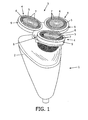
- FIG. 1 shows a conventional shaving device 1 such as known from WO 2006/067721 .
- the shaving device 1 is a rotary shaving device in which a shaving action is realized by using rotating components.
- Another well-known type of shaving device is a device in which a shaving action is realized by using reciprocating components.
- the present invention is applicable in various types of shaving devices.
- the shaving device 1 comprises a body portion 2 and a shaving head 3 in which a number of cutting units 4 are located.
- the body portion 2 is intended to be taken hold of by a user of the shaving device 1, while the cutting units 4 are intended to be positioned against skin which is to be subjected to a shaving action, for actually performing a shaving action.
- the shaving head 3 has three cutting units 4.
- Each cutting unit 4 comprises an external cutting member 5 which is shaped like a cap having an external skin contacting surface 6 and openings 7 for letting through hairs to an inside of the cutting unit 4, and an internal cutting member (not shown) having a number of cutting blades which are positioned in an inside space of the cutting unit 4 on a suitable support portion, and which are adapted to cut off the hairs.
- the support portion having the cutting blades is driven such as to rotate.
- the shaving device 1 may be equipped with any suitable driving means (not shown) such as a small electric motor.
- a shaving device 1 comprising a shaving head 3 having one or more cutting units 4, wherein each of the cutting units 4 comprises an external cutting member 5 and an internal cutting member as described in the foregoing, is as follows.
- the external cutting members 5 are moved across a portion of skin to be subjected to the shaving action by a user of the shaving device 1, and the internal cutting members are driven such as to rotate at their position right behind the external cutting members 5. Due to the movement of the cutting units 4 with respect to the skin, there is a continuous process of hairs getting trapped inside the openings 7 of the external cutting members 5 and being encountered by the cutting blades of the internal cutting members, as a result of which the hairs are cut through.
- the shaving device 1 comprises a holder 8 for holding the cutting units 4 and mounting the shaving head 3 on the body portion 2. Furthermore, in the conventional situation as illustrated in Figure 1 , each of the cutting units 4 comprises a suspension ring 9 for realizing a pivot connection between the external cutting member 5 and the holder 8, wherein a tilting axis extends in a circumferential area of the cutting unit 4, at a side of the cutting unit 4 which is near a central axis of the shaving head 3.
- the tilting axis in a structure extending from the body portion 2 to the external cutting member 5, the external cutting member 5 and the associated internal cutting member are allowed to follow a given curvature of skin to be subjected to a shaving action.
- each cutting unit 4 comprises two suspension rings 9, 10 instead of just one.
- This basic suspension ring 9 is an outer ring which is tiltable about a tilting axis located in a circumferential area of the cutting unit 4.
- another suspension ring 10 is arranged, and in this suspension ring 10the external cutting member 5 is arranged.
- the basic suspension ring 9 is pivotably connected to the holder 8, and the additional suspension ring 10, which is also denoted as end suspension ring 10, is pivotably connected to the basic suspension ring 9.
- Figure 4 serves to illustrate the various degrees of freedom of movement of a cutting unit 4, which are obtained when at least one additional suspension ring 10 is applied for suspending the external cutting member 5 relative to the holder 8.
- the holder 8 is adapted to allow for rotational movements with respect to the body portion 2, which is only partially shown in figure 4 , about two perpendicular tilting axes a, b.
- the basic suspension ring 9 is tiltable with respect to the holder 8 about a tilting axis c. In the shown example, this tilting axis c extends substantially parallel to one of the tilting axes a, b of the holder 8.
- the end suspension ring 10 is tiltable with respect to the basic suspension ring 9 about a tilting axis d, which, in the shown example, extends substantially parallel to the tilting axis c of the basic suspension ring 9 and one of the tilting axes a, b of the holder 8.
- Figure 4 clearly shows that in the shown example, the tilting axis c of the basic suspension ring 9 has an off-centre position with respect to the cutting unit 4 and the external cutting member 5, whereas the relative position as mentioned of the tilting axis d of the end suspension ring 10 is a central one.
- the external cutting member 5 is tiltable with respect to the end suspension ring 10 about a tilting axis e, which, in the shown example, extends perpendicularly to the tilting axes c, d of the suspensions rings 9, 10.
- the tilting movements of the holder 8 may be in a range of 10° in two opposite rotational directions, starting from a default position of the holder 8
- the tilting movements of the basic suspension ring 9 may be in a range of 10° in only one rotational direction, starting from a default position of the basic suspension ring 9
- the tilting movements of the end suspension ring 10 may be in a range of 7° in two opposite rotational directions, starting from a default position of the end suspension ring 10.
- the extent to which the contours of skin to be subjected to a shaving action can be followed is improved.
- an important feature of the suspension configuration in which at least two members 9, 10 which are tiltable with respect to each other are present is that a stiffness of the pivot connection of the suspension members 9, 10 with respect to each other is lower than a stiffness of the pivot connection of the basic suspension member 9 to the holder 8.
- the momentum needed to rotate the end suspension member 10 is much lower than the momentum needed to rotate the basic suspension member 9.
- contour following is improved with respect to a situation in which there is only a basic suspension ring 9, i.e. the end suspension ring 10 is omitted.
- a tilting axis is closer to skin level, the extent to which the external cutting member 5 slides over the skin during a rotation of the member 9, 10 tilting about the tilting axis is reduced, and the sensitivity to friction forces is reduced as well.
- the tilting axes c, d of the various suspension members 9, 10 may be parallel, as is the case in the shown example, but may also have a mutually different orientation, even perpendicular to one another. Another possibility is that there are more than two suspension members 9, 10, wherein an end suspension member 10 and an underlying intermediate suspension member may be tiltable in perpendicular directions.
- pivot connections are realized in various directions, the capability of contour following in the various directions is obtained, which is improved contour following with respect to a situation of movability in fewer directions.
- Figures 5 and 6 show a first alternative design of the cutting units 4.
- the shape of the end suspension member 10 has changed.
- a portion 11 of the end suspension member 10 is shaped such as to cover a portion of the underlying basic suspension member 9, as seen from a side where contact between the cutting units 4 and the skin is to take place.
- this portion 11 is a portion which is at a side of the end suspension member 10 facing away from the centre of the shaving head 3.
- the way in which the feel of the shaving units 4 is experienced by a user of the shaving device 1 is improved.
- the reason is that with the enlarged portion 11 of the end suspension member 10, a smooth skin contacting surface is realized, wherein a length of a transition between the end suspension member 10 and the basic suspension member 9 is covered and thereby prevented from contacting skin. In that way, the possibility of a smooth gliding of the external cutting members 5 and the surrounding structures over the skin is enhanced.
- Figures 7, 8 and 9 show a second alternative design of the cutting units 4.
- the end suspension member 10 is capable of completely covering the basic suspension member 9, so that there is no longer a transition between the suspension members 9, 10 where contact to the skin may take place.
- a cutting unit 4 of the shaving device 1 i.e. designs with suspension members 9, 10 comprising rings in a concentric arrangement, allow for a compact structure of the cutting unit 4.
- other shapes and configurations of the suspension members 9, 10 are feasible as well, as long as these members 9, 10 are capable of constituting a connection between the holder 8 and the external cutting member 5, wherein there is a pivot connection both at the location of the connection of the suspension members 9, 10 to the holder 8 and at the location where two suspension members 9, 10 are connected to each other, and wherein a pivoting stiffness of the latter connection is lower than a pivoting stiffness of the first connection.
- suspension means of the shaving unit 4 comprise more than two suspension members, it is important that a stiffness of a pivoting arrangement of a suspension member is lower at a level which is further away from the holder 8 of the shaving device 1 than at a level which is closest to the holder 8.
- the cutting units 4 may be arranged such as to be detachable with respect to the body portion 2 of the shaving device 1.
- the connection between the holder 8 of the shaving head 3 and the body portion 2 may be realized in any suitable manner for allowing easy detachment and attachment.
- a shaving device 1 comprising more than one cutting unit 4, it is possible for the pivoting stiffness of pivot constructions to vary from cutting unit 4 to cutting unit 4.
- the pivoting stiffness of the pivot constructions of one cutting unit 4 does not necessarily need to be the same as the pivoting stiffness of similar pivot constructions of another cutting unit 4.
- all cutting units 4 are constructed according to the present invention, namely in such a way that a stiffness of a pivoting arrangement of a suspension member of the cutting unit 4 is lower at a level which is further away from a holder 8 of the shaving device 1 than at a level which is closest to the holder 8, as has been explained in the foregoing.
- a shaving head 3 for use in a shaving device 1 comprises at least one cutting unit 4 in which an external cutting member 5 and an internal cutting member are arranged.
- the internal cutting member is movably arranged, and the internal cutting member is adapted to perform a cutting action on hairs when moving with respect to the hairs.
- the external cutting member 5 serves for contacting skin to be subjected to a shaving action, and allowing hairs to pass from the skin to the internal cutting member.
- the external cutting member 5 may be shaped like a cap covering the internal cutting member, which cap is provided with openings 7.
- the shaving head 3 comprises a holder 8 for mounting the cutting unit 4 on a body portion 2 of a shaving device 1.
- suspension means are provided for the purpose of suspending the external cutting member 5 relative to the holder 8.
- the suspension means comprise at least two pivot constructions, wherein one pivot construction enables a member of the suspension means to be pivotable relative to the holder, and wherein another pivot construction enables the external cutting member to be pivotable relative to the suspension member as mentioned.
- a pivoting stiffness of a connection of the latter pivot construction is lower than a pivoting stiffness of the first pivot construction.
Description
- The present invention relates to a shaving head for use in a shaving device for removing hairs from skin by cutting through the hairs, comprising at least one cutting unit, and a holder for holding the cutting unit, which holder is intended to be mounted on a body portion of the shaving device, which body portion is intended to be taken hold of by a user of the shaving device, and serves for accommodating various members of the shaving device,
wherein the cutting unit comprises an external cutting member having a surface which is intended for contacting skin during a shaving action, and which is interrupted by openings for allowing hairs to pass, wherein the cutting unit further comprises an internal cutting member which is drivable for movement along the openings in the surface of the external cutting member, and which is adapted to cut through hairs during such movement,
wherein the external cutting member is suspended relative to the holder through suspension means comprising: - a suspension member, and
- a first pivot construction by means of which the suspension member is pivotable relative to the holder, a tilting axis of the first pivot construction extending in a circumferential area of the cutting unit at a side of the cutting unit which is near a central axis of the shaving head.
- Furthermore, the present invention relates to a shaving device for removing hairs from skin by cutting through the hairs, comprising a body portion which is intended to be taken hold of by a user of the shaving device, and which serves for accommodating various members of the shaving device, and a shaving head as mentioned.
- An example of a shaving device comprising a body portion, and a shaving head having at least one cutting unit and a holder as described above is known from
WO 2006/067721 . The shaving device is a so-called rotary shaving device, i.e. a shaving device in which the internal cutting member comprises a ring-shaped support portion which is provided with a number of cutting blades, wherein the support portion is driven such as to rotate during operation of the shaving device. In the example known fromWO 2006/067721 , the shaving head of the shaving device is equipped with three cutting units. The external cutting member of the cutting units is shaped like a cap which serves for covering the internal cutting member, which is intended to be used for contacting portions of skin to be subjected to a shaving action, and which is provided with openings for letting through hairs from the portions of skin to the cutting blades of the internal cutting member. It is understood that a main function of the external cutting member is avoiding direct contact between the cutting blades of the internal cutting member and the portions of skin, so that skin damage is prevented. - The shaving device comprises means such as a motor for driving the internal cutting members. Proper use of the shaving device involves movement of the shaving device in such a way that a surface of the external cutting members glides over portions of skin. In the process, hairs protruding from the skin are continuously caught in the openings of the external cutting members and are cut through as soon as they are encountered by the moving cutting blades of the internal cutting members, wherein edges of the openings of the external cutting member serve as counter cutting edges.
- In each of the cutting units, the external cutting member is suspended relative to the holder through a suspension member. The suspension member has a generally circular shape, and is tiltable relative to the holder about a tilting axis. The three cutting units are arranged in a symmetrical configuration about a central axis, and means for driving the internal cutting members of the cutting units comprise a central drive shaft, a gear wheel arranged on the drive shaft, and a gear wheel per cutting unit. The central gear wheel is arranged such as to engage all three gear wheels of the cutting units and drive these gear wheels. The tilting axes of the suspension members of the cutting units extend in an area where the gear wheels of the cutting members engage the central gear wheel, i.e. in an area closer to the circumference of the cutting units than to a central position.
- Although the use of the shaving device known from
WO 2006/067721 yields good shaving results, there is a need for further improvement. A number of disadvantages appear to be associated with the shaving device. For example, when the shaving device is applied for a shaving action on the face, following the facial contours involves tilting movements of the suspension members of the cutting units about their tilting axes. In the process, it appears that a reaction on the skin involves a sliding effect, which results in frequently changing stretching and compressing of the skin. Furthermore, there appears to be a non-uniform skin pressure distribution between skin and cutting units. Also, it is only possible to closely follow purely convex and concave contours. -
EP 1 862 271 A1 - It is an object of the present invention to improve the shaving results and the feel experienced by a user of the shaving device by eliminating the above-mentioned disadvantages. The object is achieved by providing a shaving head in which the means for suspending the external cutting member relative to the holder of the shaving head comprise a second pivot construction, by means of which the external cutting member is pivotable relative to the suspension member, in addition to the suspension member and the first pivot construction by means of which the suspension member is pivotable relative to the holder, wherein a pivoting stiffness of the second pivot construction is lower than a pivoting stiffness of the first pivot construction, and wherein a tilting axis of the second pivot construction extends in an area associated with a centre of the external cutting member.
- For the sake of clarity, it is noted that the pivoting stiffness is directly related to a tilting momentum that is needed to realize a defined tilting angle in a pivot construction. The higher the tilting momentum needed to realize a defined tilting angle, the higher the pivoting stiffness. This may be realized on the basis of a steeper relation between the tilting momentum and the tilting angle, but it is also possible that there is a threshold value of the tilting momentum, which needs to be exerted before a tilting movement and a tilting angle may actually be realized. In such a case, according to the present invention, the threshold value as mentioned is lower for the second pivot construction than for the first pivot construction. The possibility of having a threshold value of the tilting momentum may also be denoted as prestress in a pivot connection, wherein a pivoting stiffness is higher when it takes a higher momentum to move a pivotably arranged member from a default rest position.
- In comparison with the shaving head of the shaving device known from
WO 2006/067721 , the at least one cutting unit of the shaving head according to the present invention does not only comprise a first pivot construction for realizing a pivoting arrangement of the suspension member with respect to the holder, but also a second pivot construction for realizing a pivoting arrangement of the external cutting member with respect to the suspension member. - Within the scope of the present invention, the number of pivot constructions of the suspension means may be any desired number. In a practical embodiment of the shaving head according to the present invention, there may be at least one additional suspension member besides the suspension member which is located at the side of the holder. In the following, for the sake of clarity, the suspension member which is located at the side of the holder will be denoted as basic suspension member. In case the suspension means comprise two or more suspension members, the suspension member which is located at the side of the external cutting member will be denoted as end suspension member, and any other suspension member, besides the basic suspension member and the end suspension member, will be denoted as intermediate suspension member.
- For example, the suspension means of the shaving head according to the present invention may comprise two suspension members, wherein the end suspension member is pivotable relative to the basic suspension member by means of the second pivot construction as defined in the foregoing. According to another possibility existing within the scope of the present invention, there are three pivot constructions and two suspension members in the suspension means, wherein the end suspension member is pivotable relative to the basic suspension member by means of the second pivot construction, wherein the external cutting member is pivotable relative to the end suspension member by means of a third pivot construction, and wherein both the pivoting stiffness of the second pivot construction and a pivoting stiffness of the third pivot construction are lower than the pivoting stiffness of the first pivot construction.
- In any case, having suspension means comprising at least two pivot constructions makes it possible to have a tilting axis which has a more or less central position in the cutting unit, and which is relatively close to skin level. Hence, the application of at least one additional pivot construction may solve most of the problems as mentioned in the foregoing, particularly the sliding effect on the skin and the non-uniform pressure distribution on the cutting unit. Furthermore, the contour following capability of the cutting unit is improved to an unexpectedly large extent by making sure that a pivoting stiffness of a pivot construction other than the first pivot construction is lower than a pivoting stiffness of the first pivot construction. An explanation can be found in the observation that a momentum which is needed to rotate a member suspended with low pivoting stiffness is lower than a momentum which is needed to rotate a member with high pivoting stiffness, so that it is possible to have both good contour following capabilities in an area of relatively small curvature changes, such as within the cheek or neck area of a user's skin, and good contour following capabilities in an area of larger curvature changes, such as between cheek and neck area.
- All in all, when the present invention is applied, contour following is improved to a surprisingly large extent. Furthermore, it is possible to realize a situation in which necessary skin pressure for optimal shaving performance of a shaving device is less user-dependent. Also, sensitivity to friction between skin and cutting unit may be relatively low when the tilting axis of the at least one additional pivot construction extends close to or at skin level, and more uniform skin contact may be obtained when the tilting axes of the various pivot constructions extend in mutually different directions.
- In a practical embodiment of the shaving head according to the present invention comprising at least two suspension members, the suspension members may comprise rings which are connected to each other in a concentric arrangement at two places defining a tilting axis of the suspension members with respect to each other. In other words, the suspension members may be interconnected in a kind of cardanic arrangement. Having the suspension members in such an arrangement is a very practical manner of realizing desired tilting axes and degrees of freedom in the suspension of the external cutting member and the associated internal cutting member.
- It is possible for the end suspension member to cover at least a portion of the other suspension member(s). An advantage of such a configuration is that the feel of the cutting units may be improved, assuming a situation in which the external cutting member is surrounded by the various suspension members. In such a situation, on the basis of a covering function of the end suspension member, it is achieved that a user of the shaving device comprising the shaving head according to the present invention experiences a smooth surface rather than a surface in which transitions between various suspension members are present.
- The present invention is very well applicable in the field of rotary shaving devices, i.e. shaving devices in which the at least one internal cutting member is rotatably arranged. However, that does not alter the fact that types of movement of the internal cutting member other than a rotary movement are feasible within the scope of the present invention.
- The above-described and other aspects of the present invention will be apparent from and elucidated with reference to the following detailed description of a shaving device and shaving heads for use in a shaving device, particularly cutting units of the shaving heads.
- The present invention will now be explained in greater detail with reference to the Figures, in which equal or similar parts are indicated by the same reference signs, and in which:
-
Figure 1 diagrammatically shows a perspective view of a shaving device known per se; -
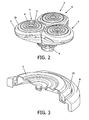
Figure 2 diagrammatically shows a perspective view of a shaving head according to the present invention; -
Figure 3 diagrammatically shows a perspective view of a section of a cutting unit of a shaving head according to the present invention; -
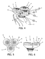
Figure 4 illustrates the degrees of freedom of a movement of a cutting unit of a shaving head according to the present invention; -
Figures 5 and 6 diagrammatically show views of an alternative shaving head, in which an end suspension member of the cutting units is adapted to cover a portion of a basic suspension member; and -
Figures 7, 8 and 9 diagrammatically show views of another alternative shaving head, in which an end suspension member of the cutting units is adapted to completely cover a basic suspension member. -
Figure 1 shows aconventional shaving device 1 such as known fromWO 2006/067721 . Theshaving device 1 is a rotary shaving device in which a shaving action is realized by using rotating components. Another well-known type of shaving device is a device in which a shaving action is realized by using reciprocating components. For the sake of completeness, it is noted that the present invention is applicable in various types of shaving devices. - The
shaving device 1 comprises abody portion 2 and ashaving head 3 in which a number of cuttingunits 4 are located. Thebody portion 2 is intended to be taken hold of by a user of theshaving device 1, while the cuttingunits 4 are intended to be positioned against skin which is to be subjected to a shaving action, for actually performing a shaving action. In the shown example, the shavinghead 3 has three cuttingunits 4. - Each cutting
unit 4 comprises anexternal cutting member 5 which is shaped like a cap having an externalskin contacting surface 6 andopenings 7 for letting through hairs to an inside of thecutting unit 4, and an internal cutting member (not shown) having a number of cutting blades which are positioned in an inside space of thecutting unit 4 on a suitable support portion, and which are adapted to cut off the hairs. During operation of theshaving device 1, the support portion having the cutting blades is driven such as to rotate. To this end, theshaving device 1 may be equipped with any suitable driving means (not shown) such as a small electric motor. - The operation of a
shaving device 1 comprising ashaving head 3 having one ormore cutting units 4, wherein each of the cuttingunits 4 comprises anexternal cutting member 5 and an internal cutting member as described in the foregoing, is as follows. When theshaving device 1 is used for performing a shaving action, theexternal cutting members 5 are moved across a portion of skin to be subjected to the shaving action by a user of theshaving device 1, and the internal cutting members are driven such as to rotate at their position right behind theexternal cutting members 5. Due to the movement of the cuttingunits 4 with respect to the skin, there is a continuous process of hairs getting trapped inside theopenings 7 of theexternal cutting members 5 and being encountered by the cutting blades of the internal cutting members, as a result of which the hairs are cut through. - The
shaving device 1 comprises aholder 8 for holding the cuttingunits 4 and mounting the shavinghead 3 on thebody portion 2. Furthermore, in the conventional situation as illustrated inFigure 1 , each of the cuttingunits 4 comprises asuspension ring 9 for realizing a pivot connection between theexternal cutting member 5 and theholder 8, wherein a tilting axis extends in a circumferential area of thecutting unit 4, at a side of thecutting unit 4 which is near a central axis of the shavinghead 3. By having the tilting axis in a structure extending from thebody portion 2 to theexternal cutting member 5, theexternal cutting member 5 and the associated internal cutting member are allowed to follow a given curvature of skin to be subjected to a shaving action. - The present invention relates to the way in which the
external cutting members 5 of the cuttingunits 4 are suspended relative to theholder 8.Figure 2 shows an embodiment of ashaving head 3 according to the present invention. In comparison with the conventional situation, each cuttingunit 4 comprises two suspension rings 9, 10 instead of just one. In particular, there is abasic suspension ring 9 which is comparable to thesuspension ring 9 which is present in the conventional situation. Thisbasic suspension ring 9 is an outer ring which is tiltable about a tilting axis located in a circumferential area of thecutting unit 4. Inside thebasic suspension ring 9, in a concentric arrangement, anothersuspension ring 10 is arranged, and in this suspension ring 10the external cuttingmember 5 is arranged. Thebasic suspension ring 9 is pivotably connected to theholder 8, and theadditional suspension ring 10, which is also denoted asend suspension ring 10, is pivotably connected to thebasic suspension ring 9. - In
Figure 3 , the configuration of theexternal cutting member 5 and the suspension rings 9, 10 is clearly illustrated. In the concentric arrangement as mentioned, the suspension rings 9, 10 are connected to each other at two places which are located on an imaginary straight line intersecting the centre of the concentric arrangement, and in this way, the pivot connection between the suspension rings 9, 10 is obtained. For the sake of completeness, it is noted that in the diagrammatic depiction inFigure 3 , details like theopenings 7 in theskin contacting surface 6 of theexternal cutting member 5 are not shown. -
Figure 4 serves to illustrate the various degrees of freedom of movement of acutting unit 4, which are obtained when at least oneadditional suspension ring 10 is applied for suspending theexternal cutting member 5 relative to theholder 8. In the first place, theholder 8 is adapted to allow for rotational movements with respect to thebody portion 2, which is only partially shown infigure 4 , about two perpendicular tilting axes a, b. In the second place, thebasic suspension ring 9 is tiltable with respect to theholder 8 about a tilting axis c. In the shown example, this tilting axis c extends substantially parallel to one of the tilting axes a, b of theholder 8. In the third place, theend suspension ring 10 is tiltable with respect to thebasic suspension ring 9 about a tilting axis d, which, in the shown example, extends substantially parallel to the tilting axis c of thebasic suspension ring 9 and one of the tilting axes a, b of theholder 8. Furthermore,Figure 4 clearly shows that in the shown example, the tilting axis c of thebasic suspension ring 9 has an off-centre position with respect to thecutting unit 4 and theexternal cutting member 5, whereas the relative position as mentioned of the tilting axis d of theend suspension ring 10 is a central one. In the fourth place, theexternal cutting member 5 is tiltable with respect to theend suspension ring 10 about a tilting axis e, which, in the shown example, extends perpendicularly to the tilting axes c, d of the suspensions rings 9, 10. - In view of the overall construction of the
shaving device 1 and the desired application of theshaving device 1, it will be understood that there is only a need for tilting movements of theholder 8 and the suspension rings 9, 10 in limited ranges. For example, the tilting movements of theholder 8 may be in a range of 10° in two opposite rotational directions, starting from a default position of theholder 8, and the tilting movements of thebasic suspension ring 9 may be in a range of 10° in only one rotational direction, starting from a default position of thebasic suspension ring 9, and the tilting movements of theend suspension ring 10 may be in a range of 7° in two opposite rotational directions, starting from a default position of theend suspension ring 10. - In the
shaving device 1 according to the present invention, the extent to which the contours of skin to be subjected to a shaving action can be followed is improved. In this respect, it is noted that an important feature of the suspension configuration in which at least twomembers suspension members basic suspension member 9 to theholder 8. Hence, the momentum needed to rotate theend suspension member 10 is much lower than the momentum needed to rotate thebasic suspension member 9. An advantage of this fact appears to be that a good contour following performance is obtained at two levels, namely at the level of an area of relatively small curvature changes and at the level of an area of relatively large curvature changes, wherein theend suspension member 10 is primarily the member which allows for coverage of the first area, and wherein thebasic suspension member 9 is primarily the member which allows for coverage of the latter area. - Another factor contributing to contour following is to have a tilting axis which is closer to skin level. In the shown example, the tilting axis d of the
end suspension ring 10 with respect to thebasic suspension ring 9 is closer to skin level than the tilting axis c of thebasic suspension ring 9 with respect to theholder 8. On the basis of this fact, contour following is improved with respect to a situation in which there is only abasic suspension ring 9, i.e. theend suspension ring 10 is omitted. When a tilting axis is closer to skin level, the extent to which theexternal cutting member 5 slides over the skin during a rotation of themember - The tilting axes c, d of the
various suspension members suspension members end suspension member 10 and an underlying intermediate suspension member may be tiltable in perpendicular directions. When pivot connections are realized in various directions, the capability of contour following in the various directions is obtained, which is improved contour following with respect to a situation of movability in fewer directions. -
Figures 5 and 6 show a first alternative design of thecutting units 4. When compared to the design of the cuttingunits 4 shown inFigures 2-4 , the shape of theend suspension member 10 has changed. In particular, aportion 11 of theend suspension member 10 is shaped such as to cover a portion of the underlyingbasic suspension member 9, as seen from a side where contact between the cuttingunits 4 and the skin is to take place. In the shown example, thisportion 11 is a portion which is at a side of theend suspension member 10 facing away from the centre of the shavinghead 3. - With the alternative design of the
end suspension member 10, the way in which the feel of theshaving units 4 is experienced by a user of theshaving device 1 is improved. The reason is that with theenlarged portion 11 of theend suspension member 10, a smooth skin contacting surface is realized, wherein a length of a transition between theend suspension member 10 and thebasic suspension member 9 is covered and thereby prevented from contacting skin. In that way, the possibility of a smooth gliding of theexternal cutting members 5 and the surrounding structures over the skin is enhanced. -
Figures 7, 8 and 9 show a second alternative design of thecutting units 4. According to this design, theend suspension member 10 is capable of completely covering thebasic suspension member 9, so that there is no longer a transition between thesuspension members - It will be clear to a person skilled in the art that the scope of the present invention is not limited to the examples discussed in the foregoing, but that several amendments and modifications thereof are possible without deviating from the scope of the present invention as defined in the attached claims. While the present invention has been illustrated and described in detail in the Figures and the description, such illustration and description are to be considered illustrative or exemplary only, and not restrictive. The present invention is not limited to the disclosed embodiments.
- Variations to the disclosed embodiments can be understood and effected by a person skilled in the art in practicing the claimed invention, from a study of the Figures, the description and the attached claims. In the claims, the word "comprising" does not exclude other steps or elements, and the indefinite article "a" or "an" does not exclude a plurality. The mere fact that certain measures are recited in mutually different dependent claims does not indicate that a combination of these measures cannot be used to advantage. Any reference signs in the claims should not be construed as limiting the scope of the present invention.
- It is noted that the designs of a
cutting unit 4 of theshaving device 1 according to the present invention as shown in the Figures, i.e. designs withsuspension members cutting unit 4. Nevertheless, other shapes and configurations of thesuspension members members holder 8 and theexternal cutting member 5, wherein there is a pivot connection both at the location of the connection of thesuspension members holder 8 and at the location where twosuspension members shaving unit 4 comprise more than two suspension members, it is important that a stiffness of a pivoting arrangement of a suspension member is lower at a level which is further away from theholder 8 of theshaving device 1 than at a level which is closest to theholder 8. - For the sake of completeness, it is noted that the cutting
units 4 may be arranged such as to be detachable with respect to thebody portion 2 of theshaving device 1. For example, it may be possible for a user to remove theentire shaving head 3 from thebody portion 2 for cleaning purposes, wherein the connection between theholder 8 of the shavinghead 3 and thebody portion 2 may be realized in any suitable manner for allowing easy detachment and attachment. - In a
shaving device 1 comprising more than onecutting unit 4, it is possible for the pivoting stiffness of pivot constructions to vary from cuttingunit 4 to cuttingunit 4. In other words, the pivoting stiffness of the pivot constructions of onecutting unit 4 does not necessarily need to be the same as the pivoting stiffness of similar pivot constructions of anothercutting unit 4. Nevertheless, in ashaving device 1, it is preferred that all cuttingunits 4 are constructed according to the present invention, namely in such a way that a stiffness of a pivoting arrangement of a suspension member of thecutting unit 4 is lower at a level which is further away from aholder 8 of theshaving device 1 than at a level which is closest to theholder 8, as has been explained in the foregoing. - The present invention can be summarized as follows. A shaving
head 3 for use in ashaving device 1 comprises at least onecutting unit 4 in which anexternal cutting member 5 and an internal cutting member are arranged. In particular, the internal cutting member is movably arranged, and the internal cutting member is adapted to perform a cutting action on hairs when moving with respect to the hairs. Theexternal cutting member 5 serves for contacting skin to be subjected to a shaving action, and allowing hairs to pass from the skin to the internal cutting member. To this end, theexternal cutting member 5 may be shaped like a cap covering the internal cutting member, which cap is provided withopenings 7. - In addition to the
cutting unit 4, the shavinghead 3 comprises aholder 8 for mounting thecutting unit 4 on abody portion 2 of ashaving device 1. For the purpose of suspending theexternal cutting member 5 relative to theholder 8, suspension means are provided. According to the present invention, the suspension means comprise at least two pivot constructions, wherein one pivot construction enables a member of the suspension means to be pivotable relative to the holder, and wherein another pivot construction enables the external cutting member to be pivotable relative to the suspension member as mentioned. Furthermore, a pivoting stiffness of a connection of the latter pivot construction is lower than a pivoting stiffness of the first pivot construction. - On the basis of the features of the suspension means as mentioned, skin contour following is improved, wherein good contour following performance is obtained at two levels, namely at the level of an area of relatively small curvature changes and at the level of an area of relatively large curvature changes.
Claims (14)
- A shaving head (3) for use in a shaving device (1) for removing hairs from skin by cutting through the hairs, comprising at least one cutting unit (4), and a holder (8) for holding the cutting unit (4), which holder (8) is intended to be mounted on a body portion (2) of the shaving device (1), which body portion (2) is intended to be taken hold of by a user of the shaving device (1), and serves for accommodating various members of the shaving device (1),
wherein the cutting unit (4) comprises an external cutting member (5) having a surface (6) which is intended for contacting skin during a shaving action, and which is interrupted by openings (7) for allowing hairs to pass,
wherein the cutting unit (4) further comprises an internal cutting member which is drivable for movement along the openings (7) in the surface (6) of the external cutting member (5), and which is adapted to cut through hairs during such movement, wherein the external cutting member (5) is suspended relative to the holder (8) through suspension means comprising:- a suspension member (9),- a first pivot construction by means of which the suspension member (9) is pivotable relative to the holder (8), a tilting axis (c) of the first pivot construction extending in a circumferential area of the cutting unit (4) at a side of the cutting unit (4) which is near a central axis of the shaving head (3),characterized in that the suspension means comprise a second pivot construction by means of which the external cutting member (5) is pivotable relative to the suspension member (9), wherein a pivoting stiffness of the second pivot construction is lower than a pivoting stiffness of the first pivot construction, and wherein a tilting axis (d) of the second pivot construction extends in an area associated with a centre of the external cutting member (5). - A shaving head (3) as claimed in claim 1, wherein the pivoting stiffness of the pivot constructions is related to a threshold value of a tilting momentum, which needs to be exerted before a tilting movement and a tilting angle may actually be realized in the pivot constructions, starting from a default rest position of the pivot constructions, and wherein the threshold value as mentioned is lower for the second pivot construction than for the first pivot construction.
- A shaving head (3) as claimed in claim 1, wherein the suspension member (9) is a first suspension member, and wherein the external cutting member (5) is fixedly mounted to a second suspension member (10) which is also part of the suspension means, and which is pivotable relative to the first suspension member (9) by means of the second pivot construction.
- A shaving head (3) as claimed in claim 3, wherein the suspension members (9, 10) comprise rings which are connected to each other in a concentric arrangement at two places defining a tilting axis (d) of the suspension members (9, 10) with respect to each other.
- A shaving head (3) as claimed in claim 3, wherein, as seen from a side where contact between the cutting unit (4) and the skin is to take place, the first suspension member (9) underlies the second suspension member (10) and the second suspension member (10) covers at least a portion of the first suspension member (9), so that the covered portion is prevented from contacting skin.
- A shaving head (3) as claimed in claim 1, wherein tilting axes (c, d) of the first pivot construction and the second pivot construction extend at mutually different levels with respect to the skin-contacting surface (6) of the external cutting member (5).
- A shaving head (3) as claimed in claim 6, wherein a tilting axis (c) of the first pivot construction is at a level which is further away from a level of the skin-contacting surface (6) of the external cutting member (5) than a tilting axis (d) of the second pivot construction.
- A shaving head (3) as claimed in claim 1, wherein tilting axes (c, d) of the first pivot construction and the second pivot construction extend in mutually different directions.
- A shaving head (3) as claimed in claim 1, wherein the suspension member (9) is a first suspension member, and wherein the external cutting member (5) is pivotable relative to a second suspension member (10) which is also part of the suspension means, by means of a third pivot construction, wherein the second suspension member (10) is pivotable relative to the first suspension member (9) by means of the second pivot construction, and wherein both the pivoting stiffness of the second pivot construction and the pivoting stiffness of the third pivot construction are lower than the pivoting stiffness of the first pivot construction.
- A shaving head (3) as claimed in claim 9, wherein the pivoting stiffness of the second pivot construction and the pivoting stiffness of the third pivot construction are substantially equal to each other.
- A shaving head (3) as claimed in claim 9, wherein tilting axes of the second pivot construction and the third pivot construction extend in mutually different directions.
- A shaving head (3) as claimed in claim 1, wherein the internal cutting member is rotatably arranged.
- A shaving device (1) for removing hairs from skin by cutting through the hairs, comprising a body portion (2) which is intended to be taken hold of by a user of the shaving device (1), and which serves for accommodating various members of the shaving device (1), and a shaving head (3) as claimed in claim 1.
- A shaving device (1) as claimed in claim 13, wherein the shaving head (3) comprises at least two cutting units (4), wherein means for driving the internal cutting members of the cutting units (4) comprise a gear wheel per cutting unit (4) and a central gear wheel for driving the gear wheels of the cutting units (4), and wherein, in each of the cutting units (4), a tilting axis (c) of the suspension member (9) extends in an area where the gear wheel of the cutting unit (4) engages the central gear wheel.
Priority Applications (1)
| Application Number | Priority Date | Filing Date | Title |
|---|---|---|---|
| EP20100708630 EP2406042B1 (en) | 2009-03-09 | 2010-03-02 | Shaving device with improved contour following |
Applications Claiming Priority (3)
| Application Number | Priority Date | Filing Date | Title |
|---|---|---|---|
| EP09154650 | 2009-03-09 | ||
| EP20100708630 EP2406042B1 (en) | 2009-03-09 | 2010-03-02 | Shaving device with improved contour following |
| PCT/IB2010/050890 WO2010103425A1 (en) | 2009-03-09 | 2010-03-02 | Shaving device with improved contour following |
Publications (2)
| Publication Number | Publication Date |
|---|---|
| EP2406042A1 EP2406042A1 (en) | 2012-01-18 |
| EP2406042B1 true EP2406042B1 (en) | 2014-05-21 |
Family
ID=42199755
Family Applications (1)
| Application Number | Title | Priority Date | Filing Date |
|---|---|---|---|
| EP20100708630 Active EP2406042B1 (en) | 2009-03-09 | 2010-03-02 | Shaving device with improved contour following |
Country Status (9)
| Country | Link |
|---|---|
| US (2) | US9216513B2 (en) |
| EP (1) | EP2406042B1 (en) |
| JP (2) | JP5701781B2 (en) |
| KR (1) | KR101782072B1 (en) |
| CN (1) | CN102348544B (en) |
| BR (1) | BRPI1006662B1 (en) |
| CA (1) | CA2754676A1 (en) |
| RU (1) | RU2524025C2 (en) |
| WO (1) | WO2010103425A1 (en) |
Cited By (2)
| Publication number | Priority date | Publication date | Assignee | Title |
|---|---|---|---|---|
| US20160199987A1 (en) * | 2009-03-09 | 2016-07-14 | Koninklijke Philips N.V. | Shaving device with improved contour following |
| EP3842194A1 (en) | 2019-12-24 | 2021-06-30 | Koninklijke Philips N.V. | Shaving unit having hair-cutting units with first and second pivot axes |
Families Citing this family (30)
| Publication number | Priority date | Publication date | Assignee | Title |
|---|---|---|---|---|
| WO2008062339A1 (en) * | 2006-11-20 | 2008-05-29 | Koninklijke Philips Electronics N.V. | Rotary shaver with improved support structure for shaving heads |
| JP5207457B2 (en) * | 2008-06-27 | 2013-06-12 | 株式会社泉精器製作所 | Rotary electric razor |
| JP5339338B2 (en) * | 2008-06-27 | 2013-11-13 | 株式会社泉精器製作所 | Rotary electric razor |
| US8341846B1 (en) * | 2008-11-24 | 2013-01-01 | Lonnie Holmes | Hair clippers with electrically adjustable blades |
| US9027251B2 (en) | 2009-04-29 | 2015-05-12 | Spectrum Brands, Inc. | Rotary electric shaver |
| JP5473462B2 (en) * | 2009-08-06 | 2014-04-16 | 株式会社泉精器製作所 | Rotary electric razor |
| CN102626933A (en) * | 2012-04-10 | 2012-08-08 | 上海奔腾电工有限公司 | Shaver head mechanism |
| US9174349B2 (en) | 2013-01-11 | 2015-11-03 | Spectrum Brands, Inc. | Rotary electric shaver |
| CN105377514B (en) * | 2013-05-16 | 2017-05-10 | 皇家飞利浦有限公司 | Shaving head with pivotable shaving unit |
| WO2015025064A1 (en) * | 2013-11-05 | 2015-02-26 | Koninklijke Philips N.V. | A personal care device |
| USD737516S1 (en) * | 2014-01-02 | 2015-08-25 | Spectrum Brands, Inc. | Shaver |
| WO2015169625A1 (en) * | 2014-05-07 | 2015-11-12 | Koninklijke Philips N.V. | Improved shaving device |
| AU361921S (en) * | 2014-10-24 | 2015-05-21 | Koninklijke Philips Nv | Shaving head |
| AU361922S (en) * | 2014-10-24 | 2015-05-21 | Koninklijke Philips Nv | Shaver without shaving head |
| CL2015001001S1 (en) * | 2014-10-24 | 2015-08-07 | Koninkl Philips Nv | Electric shaver |
| USD765982S1 (en) * | 2015-01-28 | 2016-09-13 | Thomas Nichols | Handheld motorized facial brush having three floating heads |
| USD808077S1 (en) * | 2015-08-17 | 2018-01-16 | Koninklijke Philips N.V. | Three head dry shaver |
| US11260549B2 (en) | 2017-01-27 | 2022-03-01 | Koninklijke Philips N.V. | Shaving unit with drive spindles extending in open space |
| WO2018138302A1 (en) * | 2017-01-27 | 2018-08-02 | Koninklijke Philips N.V. | Shaving unit having cutting units with a flush hole for cleaning a hair collection chamber |
| RU2745744C2 (en) * | 2017-01-27 | 2021-03-31 | Конинклейке Филипс Н.В. | Shaving unit containing cutting units with primary rotary axes |
| RU2739743C1 (en) * | 2017-01-27 | 2020-12-28 | Конинклейке Филипс Н.В. | Shaving unit and shaving device with support structure for external cutting element |
| ES2900466T3 (en) * | 2017-10-06 | 2022-03-17 | Braun Gmbh | epilator |
| US20190254360A1 (en) * | 2018-02-18 | 2019-08-22 | Bader Abdullah ALMALKI | Autonomous personal grooming apparatus, system and method |
| EP3546146B1 (en) * | 2018-03-27 | 2021-08-18 | Braun GmbH | Hair removal device |
| EP3546149B1 (en) * | 2018-03-27 | 2021-05-12 | Braun GmbH | Hair removal device |
| EP3546151A1 (en) | 2018-03-27 | 2019-10-02 | Braun GmbH | Personal care device |
| US20210069920A1 (en) * | 2019-09-05 | 2021-03-11 | Skull Shaver, Llc | Pivoting rotary 4 blade razor head |
| EP3825078A1 (en) * | 2019-11-19 | 2021-05-26 | Koninklijke Philips N.V. | A shaving unit and an electric shaver having the shaving unit |
| EP3895856A1 (en) * | 2020-04-14 | 2021-10-20 | Koninklijke Philips N.V. | Reducing sound production in a hair-cutting unit comprising an external cutting member and a rotatable internal cutting member |
| USD965892S1 (en) * | 2020-05-20 | 2022-10-04 | Koninklijke Philips N.V. | Head for shaver |
Family Cites Families (70)
| Publication number | Priority date | Publication date | Assignee | Title |
|---|---|---|---|---|
| US3715803A (en) | 1971-02-16 | 1973-02-13 | T Tyler | Rotary dry shaver with tiltable shear plates |
| NL7704475A (en) * | 1977-04-25 | 1978-10-27 | Philips Nv | SHAVER. |
| GB2266070A (en) * | 1992-04-10 | 1993-10-20 | Gillette Co | Dry shaver |
| GB2266080A (en) | 1992-04-16 | 1993-10-20 | Rolls Royce Plc | Mounting arrangement for a gas turbine engine. |
| US5625950A (en) * | 1994-07-19 | 1997-05-06 | U.S. Philips Corporation | Shaving apparatus |
| USD424746S (en) * | 1998-07-29 | 2000-05-09 | U.S. Philips Corporation | Dry shaver |
| CN2411880Y (en) | 2000-03-15 | 2000-12-27 | 上海鼎铃电器有限公司 | Fixing and active blade floater of rotary electric razor |
| USD549873S1 (en) * | 2000-06-09 | 2007-08-28 | Koninklijke Philips Electronics N.V. | 3-head dry shaver without display unit |
| USD502784S1 (en) * | 2001-01-11 | 2005-03-08 | Remington Corporation, L.L.C. | Rotary shaver |
| JP3979052B2 (en) * | 2001-09-25 | 2007-09-19 | 松下電工株式会社 | Reciprocating electric razor |
| CA99107S (en) * | 2001-10-16 | 2002-12-27 | Philips Electronics Ltd | Electric shaver |
| CN100376366C (en) * | 2001-11-15 | 2008-03-26 | 松下电工株式会社 | Dry shaver with a cradle shaving head |
| EP1405701B1 (en) | 2002-10-01 | 2005-06-22 | The Gillette Company | Linkage mechanism providing a virtual pivot axis for hair removal apparatus with pivotal head |
| USD506037S1 (en) * | 2003-05-28 | 2005-06-07 | Koninklijke Philips Electronics, N.V. | Shaver |
| USD495092S1 (en) * | 2003-05-28 | 2004-08-24 | Koninklijke Philips Electronics N.V. | Shaver |
| DE602005023729D1 (en) * | 2004-06-21 | 2010-11-04 | Koninkl Philips Electronics Nv | SHAVER |
| JP5021487B2 (en) | 2004-11-29 | 2012-09-05 | コーニンクレッカ フィリップス エレクトロニクス エヌ ヴィ | Shaving device having a hinge between the housing and the shaving head portion |
| ATE500932T1 (en) * | 2004-12-22 | 2011-03-15 | Koninkl Philips Electronics Nv | ROTARY RAZOR WITH IMPROVED DRIVE AND SUPPORT STRUCTURE FOR THE SHAVER HEAD |
| JP5021491B2 (en) * | 2004-12-22 | 2012-09-05 | コーニンクレッカ フィリップス エレクトロニクス エヌ ヴィ | Shaving equipment |
| JP4715425B2 (en) * | 2005-09-27 | 2011-07-06 | パナソニック電工株式会社 | Electric razor |
| JP2007130166A (en) * | 2005-11-09 | 2007-05-31 | Izumi Products Co | Electric rotary shaver |
| JP2007151925A (en) | 2005-12-07 | 2007-06-21 | Izumi Products Co | Rotary electric razor |
| USD539475S1 (en) * | 2006-01-06 | 2007-03-27 | Koninklijke Philips Electronics N.V. | Three head shaver without cartridge |
| USD539477S1 (en) * | 2006-01-11 | 2007-03-27 | Koninklijke Philips Electronics N.V. | Shaving head unit |
| USD542473S1 (en) * | 2006-02-10 | 2007-05-08 | Koninklijke Philips Electronics N.V. | Three head dry shaver |
| JP2007300944A (en) * | 2006-05-08 | 2007-11-22 | Izumi Products Co | Rotary electric razor |
| JP2007319339A (en) * | 2006-05-31 | 2007-12-13 | Izumi Products Co | Rotary type electric shaver |
| DE602007010301D1 (en) * | 2006-07-14 | 2010-12-16 | Koninkl Philips Electronics Nv | RAZOR WITH RANGE FOR COLLECTING CUT OFF HAIR |
| DE102006034050A1 (en) * | 2006-07-20 | 2008-01-24 | Braun Gmbh | Electric shaver |
| USD550901S1 (en) * | 2006-08-03 | 2007-09-11 | Koninklijke Philips Electronics N.V. | Three head dry shaver |
| US20080034591A1 (en) * | 2006-08-08 | 2008-02-14 | Kam Fai Fung | Shaver with swivel head |
| USD546001S1 (en) * | 2006-08-31 | 2007-07-03 | Philips Koninklijke Electronics N.V. | Three head brush shaver |
| WO2008062339A1 (en) * | 2006-11-20 | 2008-05-29 | Koninklijke Philips Electronics N.V. | Rotary shaver with improved support structure for shaving heads |
| USD544999S1 (en) * | 2006-12-05 | 2007-06-19 | Koninklijke Philips Electronics N.V. | 3-head dry shaver with display unit |
| USD563599S1 (en) * | 2007-03-20 | 2008-03-04 | Koninklijke Philips Electronics N.V. | Shaving head unit |
| US8718490B2 (en) | 2007-10-03 | 2014-05-06 | Nec Laboratories America, Inc. | Coherent optical orthogonal frequency division multiplexing (OFDM) reception using self optical carrier extraction |
| USD620641S1 (en) * | 2008-08-08 | 2010-07-27 | Rovcal, Inc. | Personal grooming device |
| USD620198S1 (en) * | 2008-08-08 | 2010-07-20 | Rovcal, Inc. | Personal grooming device |
| USD620642S1 (en) * | 2008-08-08 | 2010-07-27 | Rovcal, Inc. | Personal grooming device |
| USD619766S1 (en) * | 2008-08-08 | 2010-07-13 | Rovcal, Inc. | Portion of a personal grooming device |
| USD601301S1 (en) * | 2008-11-12 | 2009-09-29 | Weiguang Bao | 5-Head rechargeable shaver |
| US9009978B2 (en) * | 2009-01-09 | 2015-04-21 | Koninklijke Philips N.V. | Shaver having spaces for collecting cut-off hairs |
| CA2754676A1 (en) * | 2009-03-09 | 2010-09-16 | Koninklijke Philips Electronics N.V. | Shaving device with improved contour following |
| US9027251B2 (en) * | 2009-04-29 | 2015-05-12 | Spectrum Brands, Inc. | Rotary electric shaver |
| JP5473462B2 (en) * | 2009-08-06 | 2014-04-16 | 株式会社泉精器製作所 | Rotary electric razor |
| BR112012010751A2 (en) * | 2009-11-09 | 2020-09-08 | Koninklijke Philips Elecronics N.V | razor and shaver |
| AU331539S (en) * | 2009-12-07 | 2010-06-29 | Koninl Philips Electronics Nv | Three head dry shaver |
| USD637759S1 (en) * | 2010-05-20 | 2011-05-10 | Koninklijke Philips Electronics N.V. | Three head dry shaver |
| USD654223S1 (en) * | 2011-02-04 | 2012-02-14 | Wahl Clipper Corporation | Rotary shaver |
| CA143884S (en) * | 2011-07-04 | 2012-07-26 | Philips Electronics Ltd | Two head dry shaver |
| USD672504S1 (en) * | 2011-08-11 | 2012-12-11 | John Lyles | Electric head shaver |
| CN102626933A (en) * | 2012-04-10 | 2012-08-08 | 上海奔腾电工有限公司 | Shaver head mechanism |
| USD695962S1 (en) * | 2012-05-07 | 2013-12-17 | Koninklijke Philips N.V | Two head dry shaver |
| USD695961S1 (en) * | 2012-05-07 | 2013-12-17 | Koninklijke Philips N.V. | Two head dry shaver |
| WO2014020500A1 (en) * | 2012-08-03 | 2014-02-06 | Koninklijke Philips N.V. | Rotary shaving head having a locking retainer |
| CA153427S (en) * | 2013-04-23 | 2014-05-22 | Philips Electronics Ltd | Shaving head unit |
| USD693060S1 (en) * | 2013-04-26 | 2013-11-05 | Skull Shaver, Llc | Contoured electric head shaver |
| CN105377514B (en) * | 2013-05-16 | 2017-05-10 | 皇家飞利浦有限公司 | Shaving head with pivotable shaving unit |
| BR302013006122S1 (en) * | 2013-06-19 | 2015-02-24 | Koninkl Philips Nv | CONFIGURATION APPLIED TO SHAVING APPLIANCE |
| WO2015025064A1 (en) * | 2013-11-05 | 2015-02-26 | Koninklijke Philips N.V. | A personal care device |
| USD737516S1 (en) * | 2014-01-02 | 2015-08-25 | Spectrum Brands, Inc. | Shaver |
| USD737515S1 (en) * | 2014-01-02 | 2015-08-25 | Spectrum Brands, Inc. | Shaver |
| USD737514S1 (en) * | 2014-01-02 | 2015-08-25 | Spectrum Brands, Inc. | Electronic shaver |
| USD738042S1 (en) * | 2014-01-02 | 2015-09-01 | Spectrum Brands, Inc. | Electronic shaver |
| US11247351B2 (en) * | 2014-02-24 | 2022-02-15 | Koninklijke Philips N.V. | Rotary shaver comprising a disc-shaped element |
| JP6339417B2 (en) * | 2014-05-30 | 2018-06-06 | 株式会社泉精器製作所 | Rotary electric razor |
| AU359942S (en) * | 2014-07-11 | 2015-01-16 | Koninklijke Philips Nv | 3-head dry shaver |
| AU359948S (en) * | 2014-07-11 | 2015-01-16 | Koninklijke Philips Nv | Shaving head unit |
| JP2016059632A (en) * | 2014-09-18 | 2016-04-25 | 株式会社泉精器製作所 | Rotary type electric shaver |
| JP2016067589A (en) * | 2014-09-30 | 2016-05-09 | 株式会社泉精器製作所 | Rotary electric razor |
-
2010
- 2010-03-02 CA CA 2754676 patent/CA2754676A1/en not_active Abandoned
- 2010-03-02 BR BRPI1006662-4A patent/BRPI1006662B1/en not_active IP Right Cessation
- 2010-03-02 US US13/202,651 patent/US9216513B2/en not_active Expired - Fee Related
- 2010-03-02 EP EP20100708630 patent/EP2406042B1/en active Active
- 2010-03-02 JP JP2011553563A patent/JP5701781B2/en active Active
- 2010-03-02 RU RU2011140963/02A patent/RU2524025C2/en active
- 2010-03-02 KR KR1020117023573A patent/KR101782072B1/en active IP Right Grant
- 2010-03-02 WO PCT/IB2010/050890 patent/WO2010103425A1/en active Application Filing
- 2010-03-02 CN CN201080011168.2A patent/CN102348544B/en active Active
-
2015
- 2015-02-18 JP JP2015029192A patent/JP5883171B2/en active Active
- 2015-12-15 US US14/968,992 patent/US9713876B2/en active Active
Cited By (4)
| Publication number | Priority date | Publication date | Assignee | Title |
|---|---|---|---|---|
| US20160199987A1 (en) * | 2009-03-09 | 2016-07-14 | Koninklijke Philips N.V. | Shaving device with improved contour following |
| US9713876B2 (en) * | 2009-03-09 | 2017-07-25 | Koninklijke Philips N.V. | Shaving device with improved contour following |
| EP3842194A1 (en) | 2019-12-24 | 2021-06-30 | Koninklijke Philips N.V. | Shaving unit having hair-cutting units with first and second pivot axes |
| WO2021130350A1 (en) | 2019-12-24 | 2021-07-01 | Koninklijke Philips N.V. | Shaving unit having hair-cutting units with first and second pivot axes |
Also Published As
| Publication number | Publication date |
|---|---|
| CA2754676A1 (en) | 2010-09-16 |
| JP2015091511A (en) | 2015-05-14 |
| US20110308088A1 (en) | 2011-12-22 |
| US9713876B2 (en) | 2017-07-25 |
| CN102348544B (en) | 2014-12-03 |
| BRPI1006662A2 (en) | 2017-08-22 |
| JP5883171B2 (en) | 2016-03-09 |
| CN102348544A (en) | 2012-02-08 |
| KR101782072B1 (en) | 2017-09-26 |
| RU2011140963A (en) | 2013-04-20 |
| US9216513B2 (en) | 2015-12-22 |
| KR20110135959A (en) | 2011-12-20 |
| BRPI1006662B1 (en) | 2020-05-12 |
| JP5701781B2 (en) | 2015-04-15 |
| WO2010103425A1 (en) | 2010-09-16 |
| BRPI1006662A8 (en) | 2017-09-19 |
| US20160199987A1 (en) | 2016-07-14 |
| RU2524025C2 (en) | 2014-07-27 |
| EP2406042A1 (en) | 2012-01-18 |
| JP2012519564A (en) | 2012-08-30 |
Similar Documents
| Publication | Publication Date | Title |
|---|---|---|
| EP2406042B1 (en) | Shaving device with improved contour following | |
| US9180598B2 (en) | Shaver with hinge between housing and shaver head | |
| EP1833644B1 (en) | Rotary shavers, with improved drive and support structure for the shaving heads | |
| EP2099590B1 (en) | Cap having a comfort profile, which is intended to be applied in a shaving head of a shaving apparatus | |
| EP2213427B1 (en) | Blade assembly for electric razor | |
| EP2481535B1 (en) | A shaving machine | |
| JP4874331B2 (en) | Beard shaving system | |
| WO2003097309A1 (en) | Rotary electric shaver | |
| JP6892468B2 (en) | Electrical drive | |
| WO2003059584A1 (en) | Shaving head with rotary cutter, and shaving apparatus comprising such a shaving head | |
| JP4034665B2 (en) | Rotary electric razor | |
| JP7011738B2 (en) | Hair guide and hair cutting assembly | |
| EP4296017A1 (en) | Electric shaver with rotatable external cutting member having v-shaped hair-entry openings | |
| JPH04114690A (en) | Rotary electric shaver | |
| JP2555155C (en) |
Legal Events
| Date | Code | Title | Description |
|---|---|---|---|
| PUAI | Public reference made under article 153(3) epc to a published international application that has entered the european phase |
Free format text: ORIGINAL CODE: 0009012 |
|
| 17P | Request for examination filed |
Effective date: 20111010 |
|
| AK | Designated contracting states |
Kind code of ref document: A1 Designated state(s): AT BE BG CH CY CZ DE DK EE ES FI FR GB GR HR HU IE IS IT LI LT LU LV MC MK MT NL NO PL PT RO SE SI SK SM TR |
|
| DAX | Request for extension of the european patent (deleted) | ||
| 17Q | First examination report despatched |
Effective date: 20130103 |
|
| RAP1 | Party data changed (applicant data changed or rights of an application transferred) |
Owner name: KONINKLIJKE PHILIPS N.V. |
|
| GRAP | Despatch of communication of intention to grant a patent |
Free format text: ORIGINAL CODE: EPIDOSNIGR1 |
|
| INTG | Intention to grant announced |
Effective date: 20131212 |
|
| GRAS | Grant fee paid |
Free format text: ORIGINAL CODE: EPIDOSNIGR3 |
|
| GRAA | (expected) grant |
Free format text: ORIGINAL CODE: 0009210 |
|
| AK | Designated contracting states |
Kind code of ref document: B1 Designated state(s): AT BE BG CH CY CZ DE DK EE ES FI FR GB GR HR HU IE IS IT LI LT LU LV MC MK MT NL NO PL PT RO SE SI SK SM TR |
|
| REG | Reference to a national code |
Ref country code: GB Ref legal event code: FG4D |
|
| REG | Reference to a national code |
Ref country code: CH Ref legal event code: EP |
|
| REG | Reference to a national code |
Ref country code: AT Ref legal event code: REF Ref document number: 669372 Country of ref document: AT Kind code of ref document: T Effective date: 20140615 |
|
| REG | Reference to a national code |
Ref country code: IE Ref legal event code: FG4D |
|
| REG | Reference to a national code |
Ref country code: DE Ref legal event code: R096 Ref document number: 602010016239 Country of ref document: DE Effective date: 20140710 |
|
| REG | Reference to a national code |
Ref country code: AT Ref legal event code: MK05 Ref document number: 669372 Country of ref document: AT Kind code of ref document: T Effective date: 20140521 Ref country code: NL Ref legal event code: VDEP Effective date: 20140521 |
|
| REG | Reference to a national code |
Ref country code: LT Ref legal event code: MG4D |
|
| PG25 | Lapsed in a contracting state [announced via postgrant information from national office to epo] |
Ref country code: LT Free format text: LAPSE BECAUSE OF FAILURE TO SUBMIT A TRANSLATION OF THE DESCRIPTION OR TO PAY THE FEE WITHIN THE PRESCRIBED TIME-LIMIT Effective date: 20140521 Ref country code: IS Free format text: LAPSE BECAUSE OF FAILURE TO SUBMIT A TRANSLATION OF THE DESCRIPTION OR TO PAY THE FEE WITHIN THE PRESCRIBED TIME-LIMIT Effective date: 20140921 Ref country code: NO Free format text: LAPSE BECAUSE OF FAILURE TO SUBMIT A TRANSLATION OF THE DESCRIPTION OR TO PAY THE FEE WITHIN THE PRESCRIBED TIME-LIMIT Effective date: 20140821 Ref country code: FI Free format text: LAPSE BECAUSE OF FAILURE TO SUBMIT A TRANSLATION OF THE DESCRIPTION OR TO PAY THE FEE WITHIN THE PRESCRIBED TIME-LIMIT Effective date: 20140521 Ref country code: GR Free format text: LAPSE BECAUSE OF FAILURE TO SUBMIT A TRANSLATION OF THE DESCRIPTION OR TO PAY THE FEE WITHIN THE PRESCRIBED TIME-LIMIT Effective date: 20140822 |
|
| PG25 | Lapsed in a contracting state [announced via postgrant information from national office to epo] |
Ref country code: HR Free format text: LAPSE BECAUSE OF FAILURE TO SUBMIT A TRANSLATION OF THE DESCRIPTION OR TO PAY THE FEE WITHIN THE PRESCRIBED TIME-LIMIT Effective date: 20140521 Ref country code: ES Free format text: LAPSE BECAUSE OF FAILURE TO SUBMIT A TRANSLATION OF THE DESCRIPTION OR TO PAY THE FEE WITHIN THE PRESCRIBED TIME-LIMIT Effective date: 20140521 Ref country code: SE Free format text: LAPSE BECAUSE OF FAILURE TO SUBMIT A TRANSLATION OF THE DESCRIPTION OR TO PAY THE FEE WITHIN THE PRESCRIBED TIME-LIMIT Effective date: 20140521 Ref country code: PL Free format text: LAPSE BECAUSE OF FAILURE TO SUBMIT A TRANSLATION OF THE DESCRIPTION OR TO PAY THE FEE WITHIN THE PRESCRIBED TIME-LIMIT Effective date: 20140521 Ref country code: LV Free format text: LAPSE BECAUSE OF FAILURE TO SUBMIT A TRANSLATION OF THE DESCRIPTION OR TO PAY THE FEE WITHIN THE PRESCRIBED TIME-LIMIT Effective date: 20140521 Ref country code: AT Free format text: LAPSE BECAUSE OF FAILURE TO SUBMIT A TRANSLATION OF THE DESCRIPTION OR TO PAY THE FEE WITHIN THE PRESCRIBED TIME-LIMIT Effective date: 20140521 |
|
| PG25 | Lapsed in a contracting state [announced via postgrant information from national office to epo] |
Ref country code: PT Free format text: LAPSE BECAUSE OF FAILURE TO SUBMIT A TRANSLATION OF THE DESCRIPTION OR TO PAY THE FEE WITHIN THE PRESCRIBED TIME-LIMIT Effective date: 20140922 |
|
| PG25 | Lapsed in a contracting state [announced via postgrant information from national office to epo] |
Ref country code: DK Free format text: LAPSE BECAUSE OF FAILURE TO SUBMIT A TRANSLATION OF THE DESCRIPTION OR TO PAY THE FEE WITHIN THE PRESCRIBED TIME-LIMIT Effective date: 20140521 Ref country code: EE Free format text: LAPSE BECAUSE OF FAILURE TO SUBMIT A TRANSLATION OF THE DESCRIPTION OR TO PAY THE FEE WITHIN THE PRESCRIBED TIME-LIMIT Effective date: 20140521 Ref country code: RO Free format text: LAPSE BECAUSE OF FAILURE TO SUBMIT A TRANSLATION OF THE DESCRIPTION OR TO PAY THE FEE WITHIN THE PRESCRIBED TIME-LIMIT Effective date: 20140521 Ref country code: SK Free format text: LAPSE BECAUSE OF FAILURE TO SUBMIT A TRANSLATION OF THE DESCRIPTION OR TO PAY THE FEE WITHIN THE PRESCRIBED TIME-LIMIT Effective date: 20140521 Ref country code: BE Free format text: LAPSE BECAUSE OF FAILURE TO SUBMIT A TRANSLATION OF THE DESCRIPTION OR TO PAY THE FEE WITHIN THE PRESCRIBED TIME-LIMIT Effective date: 20140521 Ref country code: CZ Free format text: LAPSE BECAUSE OF FAILURE TO SUBMIT A TRANSLATION OF THE DESCRIPTION OR TO PAY THE FEE WITHIN THE PRESCRIBED TIME-LIMIT Effective date: 20140521 |
|
| REG | Reference to a national code |
Ref country code: DE Ref legal event code: R097 Ref document number: 602010016239 Country of ref document: DE |
|
| PG25 | Lapsed in a contracting state [announced via postgrant information from national office to epo] |
Ref country code: NL Free format text: LAPSE BECAUSE OF FAILURE TO SUBMIT A TRANSLATION OF THE DESCRIPTION OR TO PAY THE FEE WITHIN THE PRESCRIBED TIME-LIMIT Effective date: 20140521 |
|
| PLBE | No opposition filed within time limit |
Free format text: ORIGINAL CODE: 0009261 |
|
| STAA | Information on the status of an ep patent application or granted ep patent |
Free format text: STATUS: NO OPPOSITION FILED WITHIN TIME LIMIT |
|
| 26N | No opposition filed |
Effective date: 20150224 |
|
| PG25 | Lapsed in a contracting state [announced via postgrant information from national office to epo] |
Ref country code: IT Free format text: LAPSE BECAUSE OF FAILURE TO SUBMIT A TRANSLATION OF THE DESCRIPTION OR TO PAY THE FEE WITHIN THE PRESCRIBED TIME-LIMIT Effective date: 20140521 |
|
| REG | Reference to a national code |
Ref country code: DE Ref legal event code: R097 Ref document number: 602010016239 Country of ref document: DE Effective date: 20150224 |
|
| PG25 | Lapsed in a contracting state [announced via postgrant information from national office to epo] |
Ref country code: SI Free format text: LAPSE BECAUSE OF FAILURE TO SUBMIT A TRANSLATION OF THE DESCRIPTION OR TO PAY THE FEE WITHIN THE PRESCRIBED TIME-LIMIT Effective date: 20140521 |
|
| PG25 | Lapsed in a contracting state [announced via postgrant information from national office to epo] |
Ref country code: LU Free format text: LAPSE BECAUSE OF FAILURE TO SUBMIT A TRANSLATION OF THE DESCRIPTION OR TO PAY THE FEE WITHIN THE PRESCRIBED TIME-LIMIT Effective date: 20150302 Ref country code: MC Free format text: LAPSE BECAUSE OF FAILURE TO SUBMIT A TRANSLATION OF THE DESCRIPTION OR TO PAY THE FEE WITHIN THE PRESCRIBED TIME-LIMIT Effective date: 20140521 |
|
| REG | Reference to a national code |
Ref country code: CH Ref legal event code: PL |
|
| REG | Reference to a national code |
Ref country code: IE Ref legal event code: MM4A |
|
| PG25 | Lapsed in a contracting state [announced via postgrant information from national office to epo] |
Ref country code: LI Free format text: LAPSE BECAUSE OF NON-PAYMENT OF DUE FEES Effective date: 20150331 Ref country code: CH Free format text: LAPSE BECAUSE OF NON-PAYMENT OF DUE FEES Effective date: 20150331 Ref country code: IE Free format text: LAPSE BECAUSE OF NON-PAYMENT OF DUE FEES Effective date: 20150302 |
|
| REG | Reference to a national code |
Ref country code: FR Ref legal event code: PLFP Year of fee payment: 7 |
|
| PG25 | Lapsed in a contracting state [announced via postgrant information from national office to epo] |
Ref country code: MT Free format text: LAPSE BECAUSE OF FAILURE TO SUBMIT A TRANSLATION OF THE DESCRIPTION OR TO PAY THE FEE WITHIN THE PRESCRIBED TIME-LIMIT Effective date: 20140521 |
|
| REG | Reference to a national code |
Ref country code: FR Ref legal event code: PLFP Year of fee payment: 8 |
|
| PG25 | Lapsed in a contracting state [announced via postgrant information from national office to epo] |
Ref country code: SM Free format text: LAPSE BECAUSE OF FAILURE TO SUBMIT A TRANSLATION OF THE DESCRIPTION OR TO PAY THE FEE WITHIN THE PRESCRIBED TIME-LIMIT Effective date: 20140521 Ref country code: BG Free format text: LAPSE BECAUSE OF FAILURE TO SUBMIT A TRANSLATION OF THE DESCRIPTION OR TO PAY THE FEE WITHIN THE PRESCRIBED TIME-LIMIT Effective date: 20140521 Ref country code: HU Free format text: LAPSE BECAUSE OF FAILURE TO SUBMIT A TRANSLATION OF THE DESCRIPTION OR TO PAY THE FEE WITHIN THE PRESCRIBED TIME-LIMIT; INVALID AB INITIO Effective date: 20100302 |
|
| PG25 | Lapsed in a contracting state [announced via postgrant information from national office to epo] |
Ref country code: CY Free format text: LAPSE BECAUSE OF FAILURE TO SUBMIT A TRANSLATION OF THE DESCRIPTION OR TO PAY THE FEE WITHIN THE PRESCRIBED TIME-LIMIT Effective date: 20140521 |
|
| REG | Reference to a national code |
Ref country code: FR Ref legal event code: PLFP Year of fee payment: 9 |
|
| PG25 | Lapsed in a contracting state [announced via postgrant information from national office to epo] |
Ref country code: MK Free format text: LAPSE BECAUSE OF FAILURE TO SUBMIT A TRANSLATION OF THE DESCRIPTION OR TO PAY THE FEE WITHIN THE PRESCRIBED TIME-LIMIT Effective date: 20140521 |
|
| PGFP | Annual fee paid to national office [announced via postgrant information from national office to epo] |
Ref country code: TR Payment date: 20220216 Year of fee payment: 13 |
|
| PGFP | Annual fee paid to national office [announced via postgrant information from national office to epo] |
Ref country code: FR Payment date: 20230323 Year of fee payment: 14 |
|
| PGFP | Annual fee paid to national office [announced via postgrant information from national office to epo] |
Ref country code: GB Payment date: 20230321 Year of fee payment: 14 Ref country code: DE Payment date: 20220628 Year of fee payment: 14 |