EP2405323A1 - Computer and power management system for computer - Google Patents
Computer and power management system for computer Download PDFInfo
- Publication number
- EP2405323A1 EP2405323A1 EP09841104A EP09841104A EP2405323A1 EP 2405323 A1 EP2405323 A1 EP 2405323A1 EP 09841104 A EP09841104 A EP 09841104A EP 09841104 A EP09841104 A EP 09841104A EP 2405323 A1 EP2405323 A1 EP 2405323A1
- Authority
- EP
- European Patent Office
- Prior art keywords
- power
- processor
- upper limit
- limit value
- power consumption
- Prior art date
- Legal status (The legal status is an assumption and is not a legal conclusion. Google has not performed a legal analysis and makes no representation as to the accuracy of the status listed.)
- Withdrawn
Links
Images




Classifications
-
- G—PHYSICS
- G06—COMPUTING OR CALCULATING; COUNTING
- G06F—ELECTRIC DIGITAL DATA PROCESSING
- G06F1/00—Details not covered by groups G06F3/00 - G06F13/00 and G06F21/00
- G06F1/26—Power supply means, e.g. regulation thereof
- G06F1/32—Means for saving power
- G06F1/3203—Power management, i.e. event-based initiation of a power-saving mode
-
- G—PHYSICS
- G06—COMPUTING OR CALCULATING; COUNTING
- G06F—ELECTRIC DIGITAL DATA PROCESSING
- G06F1/00—Details not covered by groups G06F3/00 - G06F13/00 and G06F21/00
- G06F1/26—Power supply means, e.g. regulation thereof
- G06F1/32—Means for saving power
- G06F1/3203—Power management, i.e. event-based initiation of a power-saving mode
- G06F1/3234—Power saving characterised by the action undertaken
- G06F1/3246—Power saving characterised by the action undertaken by software initiated power-off
-
- Y—GENERAL TAGGING OF NEW TECHNOLOGICAL DEVELOPMENTS; GENERAL TAGGING OF CROSS-SECTIONAL TECHNOLOGIES SPANNING OVER SEVERAL SECTIONS OF THE IPC; TECHNICAL SUBJECTS COVERED BY FORMER USPC CROSS-REFERENCE ART COLLECTIONS [XRACs] AND DIGESTS
- Y02—TECHNOLOGIES OR APPLICATIONS FOR MITIGATION OR ADAPTATION AGAINST CLIMATE CHANGE
- Y02D—CLIMATE CHANGE MITIGATION TECHNOLOGIES IN INFORMATION AND COMMUNICATION TECHNOLOGIES [ICT], I.E. INFORMATION AND COMMUNICATION TECHNOLOGIES AIMING AT THE REDUCTION OF THEIR OWN ENERGY USE
- Y02D10/00—Energy efficient computing, e.g. low power processors, power management or thermal management
-
- Y—GENERAL TAGGING OF NEW TECHNOLOGICAL DEVELOPMENTS; GENERAL TAGGING OF CROSS-SECTIONAL TECHNOLOGIES SPANNING OVER SEVERAL SECTIONS OF THE IPC; TECHNICAL SUBJECTS COVERED BY FORMER USPC CROSS-REFERENCE ART COLLECTIONS [XRACs] AND DIGESTS
- Y02—TECHNOLOGIES OR APPLICATIONS FOR MITIGATION OR ADAPTATION AGAINST CLIMATE CHANGE
- Y02D—CLIMATE CHANGE MITIGATION TECHNOLOGIES IN INFORMATION AND COMMUNICATION TECHNOLOGIES [ICT], I.E. INFORMATION AND COMMUNICATION TECHNOLOGIES AIMING AT THE REDUCTION OF THEIR OWN ENERGY USE
- Y02D30/00—Reducing energy consumption in communication networks
- Y02D30/50—Reducing energy consumption in communication networks in wire-line communication networks, e.g. low power modes or reduced link rate
Definitions
- the present invention relates to a power management technique for managing the power consumption of a computer; e.g., a PC server or each server blade incorporated into a blade server.
- blade server refers to a system board in which processors, memory, I/Os, etc., are densely mounted on a single mother board.
- blade server refers to a server system which saves space and reduces the total cost of implementation and management while leaving its basic functions as a PC server intact by housing a plurality of server blades in a single chassis and sharing the chassis, power sources, fans, cables, etc. It is noted that this definition is also applicable to the present invention.
- each server blade within a blade server is equipped with basic functions as a PC server, it is possible to have each server blade run a different OS or application.
- power management systems for blade servers by way of example, there are such related techniques as those disclosed in Patent Documents 1 and 2.
- Patent Document 1 a special management controller for power consumption management manages the overall power consumption of the server blades within a chassis.
- the power consumption of a server blade is managed by having a management controller mounted on the server blade switch CPU operation speeds.
- the present invention provides a power management method that manages the power consumption of a computer to be at or below a defined power consumption upper limit value without any delay time caused by system control.
- a computer of the present invention comprises: a processor having a normal mode that operates at a first frequency and a power-saving mode that operates at a second frequency that is lower than the first frequency; a power-saving control unit; and a power sensor unit that measures power consumption, wherein the power sensor unit compares a power consumption upper limit value defined by the power-saving control unit with measured power consumption, and outputs an interrupt signal to the processor if the measured power consumption exceeds the power consumption upper limit value, and when the interrupt signal is inputted, the processor switches from the normal mode to the power-saving mode.
- a power management method for a computer is directed to a computer that comprises a processor having a normal mode that operates at a first frequency and a power-saving mode that operates at a second frequency that is lower than the first frequency, a power-saving control unit, and a power sensor unit that measures power consumption, the power management method comprising: a step of defining a power consumption upper limit value for the computer; a step of comparing power consumption measured by the power sensor unit with the power consumption upper limit value, and of outputting an interrupt signal from the power sensor unit to the processor when the measured power consumption exceeds the power consumption upper limit value; and a step in which the processor switches from the normal mode to the power-saving mode upon reception of the interrupt signal.
- the present invention allows for dynamic power management for a computer which is without any delay time caused by system control and is superior in power upper limit value control performance.
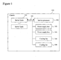
- FIG. 1 is a schematic view showing the overall configuration of a blade server.
- the blade server is such that a plurality of server blades 101 are loaded within one chassis 100, and one service processor 102 is connected via a backplane board connected to the rear faces of the server blades 101.
- a plurality of power supply boxes 103 and cooling fans 104 are disposed towards the rear in the chassis.
- the server processor 102 detects the temperature within the chassis via the backplane board, and controls the rotation speeds of the cooling fans 104.
- the power supply boxes 103 supply power to the server blades 101, the service processor 102, the cooling fans 104, etc.
- the service processor 102 is capable of accessing each of the server blades 101 via a management bus 105 within the chassis.
- FIG. 2 is a system configuration diagram showing the first embodiment of a power management system according to the present invention.
- a power sensor unit 200, a power-saving control unit 201, and a processor 205 are built into the server blade 101. It is noted that, although not shown in the figure, a power supply wire 206 is connected to each of the devices within the server blade 101.
- the term device as used herein refers to the processor 205, a power-measuring controller 203, a management controller 204, etc.
- the processor 205 has a nonnal mode that operates at a high frequency, and a power-saving mode that operates at a frequency that is lower than that.
- the power sensor unit 200 comprises a power-measuring resistor 202 and the power-measuring controller 203.
- the power-saving control unit 201 comprises the management controller 204.
- the service processor 102 is able to access the management controller 204 via the management bus 105 within the chassis.
- the management controller 204 defines an electric current upper limit value with respect to the power-measuring controller 203, and deactivates the outputting of an electric current upper limit value excess indicator signal 207 from the power-measuring controller 203.
- the management controller 204 also has a function of outputting a processor frequency reduction maintenance signal 209, as well as a function of monitoring for the electric current upper limit value excess indicator signal 207. From the perspective of the processor 205, the processor frequency reduction maintenance signal 209 is a signal comparable to the electric current upper limit value excess indicator signal 207 from the power-measuring controller 203.
- the power-measuring controller 203 simultaneously measures the input-side voltage value of, and the value of the electric current flowing through, the power-measuring resistor 202, and when it detects that the electric current value has exceeded the defined electric current upper limit value, it outputs the electric current upper limit value excess indicator signal 207.
- the electric current upper limit value excess indicator signal 207 is deactivated when a deactivation signal is inputted to the power-measuring controller 203 from the management controller 204.
- the electric current upper limit value excess indicator signal 207 is a level signal that is defined as high or low only, and the power-controlling controller 203 outputs a Low when it detects that the defined electric current upper limit value has been exceeded.
- the electric current upper limit value excess indicator signal 207 is inputted to the processor 205 as a processor frequency reduction indicator signal (interrupt signal) 208, and is also simultaneously inputted to the management controller 204 as well.
- the processor frequency reduction indicator signal 208 may be, by way of example, a processor hot signal.
- the processor 205 has a function whereby, when the frequency reduction indicator signal 208 is inputted, it transitions from the normal mode, in which it had been operating at a high frequency, to the power-saving mode referred to as P-state in which the operating frequency is reduced.
- the frequency reduction indicator signal 208 is a Low-active signal
- the processor 205 transitions to the P-state when the frequency reduction indicator signal 208 is inputted at Low, thus operating at a certain frequency that is lower than that during normal operation.
- FIG. 3 is a flowchart generally illustrating the operation of a power management system of the present invention.
- a power consumption upper limit value for the server is indicated via a management program of the service processor 102 in accordance with the user's use environment (S11)
- the service processor 102 indicates the power consumption upper limit value to the management controller 204 within the server blade via the management bus 105 within the chassis.
- the management controller 204 defines in the power-measuring controller 203 an electric current upper limit value computed from the power consumption upper limit value.
- the power-measuring controller 203 compares the electric current upper limit value with the value of the electric current flowing through the power-measuring resistor 202 (S12), and if the measured electric current value exceeds the upper limit value, lowers the operating frequency of the processor 205 to transition from normal mode to power-saving mode, thereby reducing power consumption (S13).
- FIG. 4 is a flowchart showing the details of the operation of a management controller.
- the management controller 204 computes an electric current upper limit value from the defined power consumption upper limit value (S22). Specifically, it divides the power consumption upper limit value by the input voltage value, and uses a value with a margin of reading error as the electric current upper limit value.
- the management controller 204 defines the electric current upper limit value in the power-measuring controller 203 via a management bus 210 within the server (S23). Initially, the processor 205 operates in normal mode whose operating frequency is high.
- the power-measuring controller 203 compares the value of the electric current flowing through the power-measuring resistor 202 with the defined electric current upper limit value, and, when it detects that the measured electric current value has exceeded the defined upper limit value, outputs the electric current upper limit value excess indicator signal 207 towards the processor 205 and the management controller 204 (S24). It is noted that, even while it is outputting the electric current upper limit value excess indicator signal 207, the power-measuring controller 203 continues to measure the input-side voltage value of, and the value of the electric current flowing through, the power-measuring resistor 202.
- the electric current upper limit value excess indicator signal 207 directed to the processor 205 becomes the processor frequency reduction indicator signal 208, which is an interrupt signal to the processor.
- the processor frequency reduction indicator signal 208 is inputted as an interrupt signal
- the processor 205 transitions to the P-state, which is the power-saving mode, and operates at a reduced frequency.
- the management controller 204 instantly outputs the processor frequency reduction maintenance signal 209 (S25).
- the processor frequency reduction maintenance signal 209 is a signal that is equivalent to the electric current upper limit value excess indicator signal 207, and as a result of the processor frequency reduction maintenance signal 209 being outputted, the processor frequency reduction indicator signal 208 maintains a Low-state even when the electric current upper limit value excess indicator signal 207 is deactivated, and the processor 205 operates in power-saving mode with its frequency reduced while still in the P-state.
- the management controller 204 deactivates, after a certain period and via the management bus 210 within the server, the electric current upper limit value excess indicator signal 207 that the power-measuring controller 203 is outputting (S26). Once the outputting of the electric current upper limit value excess indicator signal 207 is deactivated, the power-measuring controller 203 makes a comparison to see if the measured electric current value exceeds the upper limit value, and if the upper limit value is exceeded, it once again outputs the electric current upper limit value excess indicator signal 207.
- the management controller 204 checks if the electric current value has been successfully reduced to or below the electric current upper limit value (S27).
- the management controller 204 deactivates the outputting of the processor frequency reduction maintenance signal 209 (S28). As the outputting of the processor frequency reduction indicator signal 208 is deactivated, the processor 205 returns to normal mode, which has the higher operating frequency from before control was effected.
- step 27 if the electric current upper limit value excess indicator signal 207 has been inputted, the management controller gives a warning (S29), deactivates the outputting of the electric current upper limit value excess indicator signal 207 (S30), and thereafter deactivates the processor frequency reduction maintenance signal 209 (S28), and the processor 205 thereby returns to normal mode, which has the higher operating frequency from before control was effected.
- the management controller 204 then checks to see if the power consumption upper limit value defined by the service processor 102 has been changed (S31). If no change has been made to the power consumption upper limit value, returning to step 24, the management controller 204 transitions to monitoring the electric current upper limit value excess indicator signal 207. On the other hand, if there has been a change to the power consumption upper limit value, returning to step 21, the service processor 102 again defines the power consumption upper limit value in the management controller 204. Power management is thus performed by repeating the series of processes above.
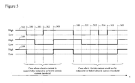
- Figure 5 is a chart showing time sequences of various signals for reducing processor frequency by means of a power management system.
- the management controller 204 detects an output of the electric current upper limit value excess indicator signal 207, it outputs the processor frequency reduction maintenance signal 209 at processor frequency reduction maintenance signal output time 301. After the processor frequency reduction maintenance signal 209 has been outputted, the management controller 204 deactivates the electric current upper limit value excess indicator signal 207 at electric current upper limit value excess indicator signal deactivation time 302.
- the management controller 204 After a certain period has lapsed from processor frequency reduction maintenance signal output time 301, the management controller 204 then monitors the output of the electric current upper limit value excess indicator signal 207. If it is confirmed that it is not being outputted at Low, the processor frequency reduction indicator signal 208 returns to High by having the processor frequency reduction maintenance signal 209 deactivated at processor frequency reduction maintenance signal deactivation time 303.
- the management controller 204 confirms, at electric current upper limit value excess indicator signal re-output time 304, that the electric current upper limit value excess indicator signal 207 is being outputted at Low, it deactivates the electric current upper limit value excess indicator signal 207 at electric current upper limit value excess indicator signal re-deactivation time 305.
- the processor frequency reduction indicator signal 208 then returns to High by having the processor frequency reduction maintenance signal 209 deactivated at processor frequency reduction maintenance signal deactivation time 303.
- FIG. 6 is a system configuration diagram showing the second embodiment of a power management system according to the present invention.
- the second embodiment differs from the first embodiment in terms of the configuration of the power-saving control unit.
- the power-saving control unit 201 of the present embodiment comprises the management controller 204 and a southbridge 400.
- the southbridge 400 causes, using a processor state controlling bus 402, the processor 205 to transition to a T-state, which is an operating state with a reduced operating frequency (power-saving mode).
- the management controller 204 causes, via a PECI (Platform Environmental Control Interface) between the processor 205 and the southbridge 400, the operating frequency of the processor 205 to transition to the T-state, which allows for a reduction down to 12.5 % of the operating frequency of the P-state, and thus reduces the operating frequency of the processor 205 to 12.5 % of that of normal mode.
- PECI Platinum Environmental Control Interface
- power control for the processor 205 is performed using the processor frequency reduction indicator signal 208 as in the first embodiment.
- the management controller 204 when reduction to or below the electric current upper limit value is not possible, the management controller 204 outputs a power control request to the southbridge 400 via the processor state controlling management bus 401.
- the southbridge 400 then causes, via the processor state controlling bus 402, the processor 205 to transition to the T-state to reduce power.
- step 21 to step 31 shown in Figure 7 Operations of the management controller 204 with respect to the second embodiment will be described with reference to Figure 7 .
- the control flow of from step 21 to step 31 shown in Figure 7 is the same as that in the first embodiment, and a detailed description thereof will therefore be omitted.
- the control subsequent to step 29 will be described.
- the management controller 204 After giving a warning (S29), the management controller 204 outputs a ower control request to the southbridge 400 via the processor state controlling management bus 401.
- the southbridge 400 causes, via the processor state controlling bus 402, the processor 205 to transition to the T-state and thus reduces the operating frequency of the processor 205 (S32).
- the service processor 102 whose purpose is, among others, to detect the temperature within the chassis via the backplane board and to control the rotation speeds of the fans, defines an electric current upper limit value in the power-measuring controller 203 via the management controller 204. It is thus possible to control the operating frequency of the processor 205 by means of the electric current upper limit value excess indicator signal 207 outputted from the power-measuring controller 203 when the power of the server blades 101 exceeds the power consumption upper limit value. In the case of this control, since the control signal is inputted directly to the processor 205 from the power-controlling controller 203 without having to go through the management controller 204, there is no delay time caused by system control.
- the present invention by defining, from the service processor 102, the power consumption upper limit value for the plurality of server blades 101 mounted within the chassis, it is possible to keep the power of the server blades 101 at or below the power consumption upper limit value without any delay time caused by system control.
- the fact that there is no delay time caused by system control it is possible to shorten the time it takes to, from when the electric current upper limit value is exceeded, bring it down to or below the electric current upper limit value, which is advantageous over conventional methods from the perspective of power upper limit value control.
- the power consumption upper limit value is inputted to the power-saving control unit 201 via the management controller 204 instead of a service processor.
- the inputted electric current consumption upper limit value is defined in the power-measuring controller 203, and power control for the PC server is carried out through processes similar to those discussed above.
Landscapes
- Engineering & Computer Science (AREA)
- Theoretical Computer Science (AREA)
- Physics & Mathematics (AREA)
- General Engineering & Computer Science (AREA)
- General Physics & Mathematics (AREA)
- Power Sources (AREA)
Abstract
Description
- The present invention relates to a power management technique for managing the power consumption of a computer; e.g., a PC server or each server blade incorporated into a blade server.
- The term blade server refers to a system board in which processors, memory, I/Os, etc., are densely mounted on a single mother board. In addition, the term blade server refers to a server system which saves space and reduces the total cost of implementation and management while leaving its basic functions as a PC server intact by housing a plurality of server blades in a single chassis and sharing the chassis, power sources, fans, cables, etc. It is noted that this definition is also applicable to the present invention.
- Since each server blade within a blade server is equipped with basic functions as a PC server, it is possible to have each server blade run a different OS or application. With respect to power management systems for blade servers, by way of example, there are such related techniques as those disclosed in Patent Documents 1 and 2. With respect to Patent Document 1, a special management controller for power consumption management manages the overall power consumption of the server blades within a chassis. With respect to Patent Document 2, the power consumption of a server blade is managed by having a management controller mounted on the server blade switch CPU operation speeds.
- Patent Document 1: JP Patent Application Publication (Kokai) No.
2005-202506 A - Patent Document 2: JP Patent Application Publication (Kokai) No.
2008-83841 A - Greater demands with respect to processor performance are beginning to be placed on blade servers as well, and there are now signs that the use of the newest processors is being considered. However, when one attempts to densely mount server blades that use processors that operate at high frequencies, power consumption problems arise. High-frequency processors, naturally, consume greater power, and as more of them are mounted, there would be constraints as to where they may be installed. For this reason, a system for defining an upper limit value with respect to server blade power consumption and for controlling the maximum average power to be at or below that upper limit value becomes necessary. In addition, such a power control system would be expected to control, in the event that the defined upper limit value is exceeded, the maximum average power to be at or below the upper limit value as quickly as possible. This expectation with respect to power consumption control similarly applies to other computers as well, such as PC servers, etc., in which high-performance processors are mounted.
- The present invention provides a power management method that manages the power consumption of a computer to be at or below a defined power consumption upper limit value without any delay time caused by system control.
- A computer of the present invention comprises: a processor having a normal mode that operates at a first frequency and a power-saving mode that operates at a second frequency that is lower than the first frequency; a power-saving control unit; and a power sensor unit that measures power consumption, wherein the power sensor unit compares a power consumption upper limit value defined by the power-saving control unit with measured power consumption, and outputs an interrupt signal to the processor if the measured power consumption exceeds the power consumption upper limit value, and when the interrupt signal is inputted, the processor switches from the normal mode to the power-saving mode.
- Further, a power management method for a computer according to the present invention is directed to a computer that comprises a processor having a normal mode that operates at a first frequency and a power-saving mode that operates at a second frequency that is lower than the first frequency, a power-saving control unit, and a power sensor unit that measures power consumption, the power management method comprising: a step of defining a power consumption upper limit value for the computer; a step of comparing power consumption measured by the power sensor unit with the power consumption upper limit value, and of outputting an interrupt signal from the power sensor unit to the processor when the measured power consumption exceeds the power consumption upper limit value; and a step in which the processor switches from the normal mode to the power-saving mode upon reception of the interrupt signal.
- According to the present invention, it is possible to control processor frequency without system control.
- The present invention allows for dynamic power management for a computer which is without any delay time caused by system control and is superior in power upper limit value control performance.
-
-
Figure 1 is a schematic view showing the overall configuration of a blade server. -
Figure 2 is a system configuration diagram showing the first embodiment of a power management system according to the present invention. -
Figure 3 is a flowchart generally illustrating the operations of a power management system of the present invention. -
Figure 4 is a flowchart showing the operations of a management controller with respect to the first embodiment. -
Figure 5 is a chart showing time sequences of signals for reducing processor frequency. -
Figure 6 is a system configuration diagram showing the second embodiment of a power management system according to the present invention. -
Figure 7 is a flowchart showing the operations of a management controller with respect to the second embodiment. -
- 100
- Chassis
- 101
- Server blade
- 102
- Service processor
- 103
- Power supply box
- 104
- Cooling fan
- 105
- Management bus within chassis
- 200
- Power sensor unit
- 201
- Power-saving control unit
- 202
- Power-measuring resistor
- 203
- Power-measuring controller
- 204
- Management controller
- 205
- Processor
- 206
- Power supply wire
- 207
- Electric current upper limit value excess indicator signal
- 208
- Processor frequency reduction indicator signal
- 209
- Processor frequency reduction maintenance signal
- 210
- Management bus within server
- 400
- Southbridge
- 401
- Processor state controlling management bus
- 402
- Processor state controlling bus
- Embodiments of the present invention are described below with reference to the drawings. Descriptions are provided below chiefly with respect to power management for server blades mounted on a blade server. However, the present invention is not limited to blade servers, and is applicable to power management for other computers as well, such as stand-alone PC servers, etc.
-
Figure 1 is a schematic view showing the overall configuration of a blade server. The blade server is such that a plurality ofserver blades 101 are loaded within onechassis 100, and oneservice processor 102 is connected via a backplane board connected to the rear faces of theserver blades 101. A plurality ofpower supply boxes 103 and coolingfans 104 are disposed towards the rear in the chassis. Theserver processor 102 detects the temperature within the chassis via the backplane board, and controls the rotation speeds of the coolingfans 104. Thepower supply boxes 103 supply power to theserver blades 101, theservice processor 102, the coolingfans 104, etc. Further, theservice processor 102 is capable of accessing each of theserver blades 101 via amanagement bus 105 within the chassis. -
Figure 2 is a system configuration diagram showing the first embodiment of a power management system according to the present invention. Apower sensor unit 200, a power-savingcontrol unit 201, and aprocessor 205 are built into theserver blade 101. It is noted that, although not shown in the figure, apower supply wire 206 is connected to each of the devices within theserver blade 101. The term device as used herein refers to theprocessor 205, a power-measuringcontroller 203, amanagement controller 204, etc. As operation modes, theprocessor 205 has a nonnal mode that operates at a high frequency, and a power-saving mode that operates at a frequency that is lower than that. - The
power sensor unit 200 comprises a power-measuringresistor 202 and the power-measuringcontroller 203. The power-savingcontrol unit 201 comprises themanagement controller 204. Theservice processor 102 is able to access themanagement controller 204 via themanagement bus 105 within the chassis. Via amanagement bus 210 within the blade, themanagement controller 204 defines an electric current upper limit value with respect to the power-measuringcontroller 203, and deactivates the outputting of an electric current upper limit value excess indicator signal 207 from the power-measuringcontroller 203. In addition, themanagement controller 204 also has a function of outputting a processor frequencyreduction maintenance signal 209, as well as a function of monitoring for the electric current upper limit valueexcess indicator signal 207. From the perspective of theprocessor 205, the processor frequencyreduction maintenance signal 209 is a signal comparable to the electric current upper limit value excess indicator signal 207 from the power-measuringcontroller 203. - The power-measuring
controller 203 simultaneously measures the input-side voltage value of, and the value of the electric current flowing through, the power-measuringresistor 202, and when it detects that the electric current value has exceeded the defined electric current upper limit value, it outputs the electric current upper limit valueexcess indicator signal 207. The electric current upper limit valueexcess indicator signal 207 is deactivated when a deactivation signal is inputted to the power-measuringcontroller 203 from themanagement controller 204. - In the present embodiment, the electric current upper limit value
excess indicator signal 207 is a level signal that is defined as high or low only, and the power-controllingcontroller 203 outputs a Low when it detects that the defined electric current upper limit value has been exceeded. The electric current upper limit valueexcess indicator signal 207 is inputted to theprocessor 205 as a processor frequency reduction indicator signal (interrupt signal) 208, and is also simultaneously inputted to themanagement controller 204 as well. The processor frequencyreduction indicator signal 208 may be, by way of example, a processor hot signal. Theprocessor 205 has a function whereby, when the frequencyreduction indicator signal 208 is inputted, it transitions from the normal mode, in which it had been operating at a high frequency, to the power-saving mode referred to as P-state in which the operating frequency is reduced. By way of example, in a power management system of the present embodiment, the frequencyreduction indicator signal 208 is a Low-active signal, and theprocessor 205 transitions to the P-state when the frequencyreduction indicator signal 208 is inputted at Low, thus operating at a certain frequency that is lower than that during normal operation. -
Figure 3 is a flowchart generally illustrating the operation of a power management system of the present invention. When a power consumption upper limit value for the server is indicated via a management program of theservice processor 102 in accordance with the user's use environment (S11), theservice processor 102 indicates the power consumption upper limit value to themanagement controller 204 within the server blade via themanagement bus 105 within the chassis. Themanagement controller 204 defines in the power-measuringcontroller 203 an electric current upper limit value computed from the power consumption upper limit value. The power-measuringcontroller 203 compares the electric current upper limit value with the value of the electric current flowing through the power-measuring resistor 202 (S12), and if the measured electric current value exceeds the upper limit value, lowers the operating frequency of theprocessor 205 to transition from normal mode to power-saving mode, thereby reducing power consumption (S13). -
Figure 4 is a flowchart showing the details of the operation of a management controller. - As the user specifies a power consumption upper limit value for the server blade to the
management controller 204 from the service processor 102 (S21), themanagement controller 204 computes an electric current upper limit value from the defined power consumption upper limit value (S22). Specifically, it divides the power consumption upper limit value by the input voltage value, and uses a value with a margin of reading error as the electric current upper limit value. Themanagement controller 204 defines the electric current upper limit value in the power-measuringcontroller 203 via amanagement bus 210 within the server (S23). Initially, theprocessor 205 operates in normal mode whose operating frequency is high. The power-measuringcontroller 203 compares the value of the electric current flowing through the power-measuringresistor 202 with the defined electric current upper limit value, and, when it detects that the measured electric current value has exceeded the defined upper limit value, outputs the electric current upper limit valueexcess indicator signal 207 towards theprocessor 205 and the management controller 204 (S24). It is noted that, even while it is outputting the electric current upper limit valueexcess indicator signal 207, the power-measuringcontroller 203 continues to measure the input-side voltage value of, and the value of the electric current flowing through, the power-measuringresistor 202. - The electric current upper limit value
excess indicator signal 207 directed to theprocessor 205 becomes the processor frequencyreduction indicator signal 208, which is an interrupt signal to the processor. As the processor frequencyreduction indicator signal 208 is inputted as an interrupt signal, theprocessor 205 transitions to the P-state, which is the power-saving mode, and operates at a reduced frequency. On the other hand, as the electric current upper limit valueexcess indicator signal 207 is inputted to themanagement controller 204, themanagement controller 204 instantly outputs the processor frequency reduction maintenance signal 209 (S25). To the processor, the processor frequencyreduction maintenance signal 209 is a signal that is equivalent to the electric current upper limit valueexcess indicator signal 207, and as a result of the processor frequencyreduction maintenance signal 209 being outputted, the processor frequencyreduction indicator signal 208 maintains a Low-state even when the electric current upper limit valueexcess indicator signal 207 is deactivated, and theprocessor 205 operates in power-saving mode with its frequency reduced while still in the P-state. - After outputting the processor frequency
reduction maintenance signal 209, themanagement controller 204 deactivates, after a certain period and via themanagement bus 210 within the server, the electric current upper limit valueexcess indicator signal 207 that the power-measuringcontroller 203 is outputting (S26). Once the outputting of the electric current upper limit valueexcess indicator signal 207 is deactivated, the power-measuringcontroller 203 makes a comparison to see if the measured electric current value exceeds the upper limit value, and if the upper limit value is exceeded, it once again outputs the electric current upper limit valueexcess indicator signal 207. By checking to see if the electric current upper limit valueexcess indicator signal 207 is inputted again after the electric current upper limit valueexcess indicator signal 207 has been deactivated, themanagement controller 204 checks if the electric current value has been successfully reduced to or below the electric current upper limit value (S27). - First, to explain a case where the electric current upper limit value
excess indicator signal 207 is not inputted to themanagement controller 204, themanagement controller 204 deactivates the outputting of the processor frequency reduction maintenance signal 209 (S28). As the outputting of the processor frequencyreduction indicator signal 208 is deactivated, theprocessor 205 returns to normal mode, which has the higher operating frequency from before control was effected. On the other hand, in the determination instep 27, if the electric current upper limit valueexcess indicator signal 207 has been inputted, the management controller gives a warning (S29), deactivates the outputting of the electric current upper limit value excess indicator signal 207 (S30), and thereafter deactivates the processor frequency reduction maintenance signal 209 (S28), and theprocessor 205 thereby returns to normal mode, which has the higher operating frequency from before control was effected. - The
management controller 204 then checks to see if the power consumption upper limit value defined by theservice processor 102 has been changed (S31). If no change has been made to the power consumption upper limit value, returning to step 24, themanagement controller 204 transitions to monitoring the electric current upper limit valueexcess indicator signal 207. On the other hand, if there has been a change to the power consumption upper limit value, returning to step 21, theservice processor 102 again defines the power consumption upper limit value in themanagement controller 204. Power management is thus performed by repeating the series of processes above. -
Figure 5 is a chart showing time sequences of various signals for reducing processor frequency by means of a power management system. - As a Low output of the electric current upper limit value
excess indicator signal 207 is made at electric current upper limit value excess indicatorsignal output time 300, a Low output of the processor frequencyreduction indicator signal 208 is made almost simultaneously. As themanagement controller 204 then detects an output of the electric current upper limit valueexcess indicator signal 207, it outputs the processor frequencyreduction maintenance signal 209 at processor frequency reduction maintenancesignal output time 301. After the processor frequencyreduction maintenance signal 209 has been outputted, themanagement controller 204 deactivates the electric current upper limit valueexcess indicator signal 207 at electric current upper limit value excess indicatorsignal deactivation time 302. - After a certain period has lapsed from processor frequency reduction maintenance
signal output time 301, themanagement controller 204 then monitors the output of the electric current upper limit valueexcess indicator signal 207. If it is confirmed that it is not being outputted at Low, the processor frequencyreduction indicator signal 208 returns to High by having the processor frequencyreduction maintenance signal 209 deactivated at processor frequency reduction maintenancesignal deactivation time 303. - On the other hand, if, after a certain period has lapsed from processor frequency reduction maintenance
signal output time 301, themanagement controller 204 confirms, at electric current upper limit value excess indicator signalre-output time 304, that the electric current upper limit valueexcess indicator signal 207 is being outputted at Low, it deactivates the electric current upper limit valueexcess indicator signal 207 at electric current upper limit value excess indicator signalre-deactivation time 305. The processor frequencyreduction indicator signal 208 then returns to High by having the processor frequencyreduction maintenance signal 209 deactivated at processor frequency reduction maintenancesignal deactivation time 303. -
Figure 6 is a system configuration diagram showing the second embodiment of a power management system according to the present invention. The second embodiment differs from the first embodiment in terms of the configuration of the power-saving control unit. The power-savingcontrol unit 201 of the present embodiment comprises themanagement controller 204 and asouthbridge 400. When a power control request is made from themanagement controller 204 via a processor state controllingmanagement bus 401, thesouthbridge 400 causes, using a processorstate controlling bus 402, theprocessor 205 to transition to a T-state, which is an operating state with a reduced operating frequency (power-saving mode). To provide a specific example, themanagement controller 204 causes, via a PECI (Platform Environmental Control Interface) between theprocessor 205 and thesouthbridge 400, the operating frequency of theprocessor 205 to transition to the T-state, which allows for a reduction down to 12.5 % of the operating frequency of the P-state, and thus reduces the operating frequency of theprocessor 205 to 12.5 % of that of normal mode. - In the second embodiment, power control for the
processor 205 is performed using the processor frequencyreduction indicator signal 208 as in the first embodiment. In this control, when reduction to or below the electric current upper limit value is not possible, themanagement controller 204 outputs a power control request to thesouthbridge 400 via the processor state controllingmanagement bus 401. Thesouthbridge 400 then causes, via the processorstate controlling bus 402, theprocessor 205 to transition to the T-state to reduce power. - Operations of the
management controller 204 with respect to the second embodiment will be described with reference toFigure 7 . The control flow of from step 21 to step 31 shown inFigure 7 is the same as that in the first embodiment, and a detailed description thereof will therefore be omitted. The control subsequent to step 29 will be described. - After giving a warning (S29), the
management controller 204 outputs a ower control request to thesouthbridge 400 via the processor state controllingmanagement bus 401. Thesouthbridge 400 causes, via the processorstate controlling bus 402, theprocessor 205 to transition to the T-state and thus reduces the operating frequency of the processor 205 (S32). - Thus, in the case of a blade server, the
service processor 102, whose purpose is, among others, to detect the temperature within the chassis via the backplane board and to control the rotation speeds of the fans, defines an electric current upper limit value in the power-measuringcontroller 203 via themanagement controller 204. It is thus possible to control the operating frequency of theprocessor 205 by means of the electric current upper limit valueexcess indicator signal 207 outputted from the power-measuringcontroller 203 when the power of theserver blades 101 exceeds the power consumption upper limit value. In the case of this control, since the control signal is inputted directly to theprocessor 205 from the power-controllingcontroller 203 without having to go through themanagement controller 204, there is no delay time caused by system control. - According to the present invention, by defining, from the
service processor 102, the power consumption upper limit value for the plurality ofserver blades 101 mounted within the chassis, it is possible to keep the power of theserver blades 101 at or below the power consumption upper limit value without any delay time caused by system control. By virtue of the fact that there is no delay time caused by system control, it is possible to shorten the time it takes to, from when the electric current upper limit value is exceeded, bring it down to or below the electric current upper limit value, which is advantageous over conventional methods from the perspective of power upper limit value control. - Descriptions have been provided above with respect to power control for server blades mounted on a blade server. If the server for which power control is to be performed is a single independent PC server instead of a blade server, the power consumption upper limit value is inputted to the power-saving
control unit 201 via themanagement controller 204 instead of a service processor. The inputted electric current consumption upper limit value is defined in the power-measuringcontroller 203, and power control for the PC server is carried out through processes similar to those discussed above.
Claims (15)
- A computer comprising:a processor having a normal mode that operates at a first frequency and a power-saving mode that operates at a second frequency that is lower than the first frequency;a power-saving control unit; anda power sensor unit that measures power consumption, whereinthe power sensor unit compares a power consumption upper limit value defined by the power-saving control unit with measured power consumption, and outputs an interrupt signal to the processor if the measured power consumption exceeds the power consumption upper limit value, andwhen the interrupt signal is inputted, the processor switches from the normal mode to the power-saving mode.
- A computer according to claim 1, further comprising a path for supplying the interrupt signal from the power sensor unit to the power-saving control unit, wherein, when the interrupt signal is inputted, the power-saving control unit outputs to the processor a signal that is equivalent to the interrupt signal, and instructs the power sensor unit to deactivate the interrupt signal.
- A computer according to claim 1 or 2, wherein the interrupt signal comprises a processor hot signal.
- A computer according to one of claims 1 to 3, wherein the computer comprises a server blade mounted on a blade server.
- A computer according to one of claims 1 to 4, wherein the power sensor unit comprises a power-measuring resistor.
- A computer according to one of claims 1 to 5, wherein, in the event that the power consumption of the computer cannot be kept at or below the power consumption upper limit value even after the processor has switched to the power-saving mode due to the interrupt signal to the processor, the power-saving control unit reduces the frequency of the processor via a platform environmental control interface of the processor.
- A computer system comprising, within one chassis, a power source, a plurality of computers and a cooling fan, wherein
the computers each comprise:a processor having a normal mode that operates at a first frequency and a power-saving mode that operates at a second frequency that is lower than the first frequency;a power-saving control unit; anda power sensor unit that measures power consumption, whereinthe power sensor unit compares a power consumption upper limit value defined by the power-saving control unit with measured power consumption, and outputs an interrupt signal to the processor if the measured power consumption exceeds the power consumption upper limit value, andwhen the interrupt signal is inputted, the processor switches from the normal mode to the power-saving mode. - A computer system according to claim 7, further comprising a service processor that controls the cooling fan, wherein
the power consumption upper limit value for each of the computers is defined from the service processor with respect to the power sensor unit via the power-saving control unit of each of the computers. - A computer system according to claim 7 or 8, further comprising a path for supplying the interrupt signal from the power sensor unit to the power-saving control unit, wherein, when the interrupt signal is inputted, the power-saving control unit outputs to the processor a signal that is equivalent to the interrupt signal, and instructs the power sensor unit to deactivate the interrupt signal.
- A computer system according to one of claims 7 to 9, wherein the interrupt signal comprises a processor hot signal.
- A computer system according to one of claims 7 to 10, wherein, in the event that the power consumption of the computers cannot be kept at or below the power consumption upper limit value even after the processor has been placed in the power-saving mode with the interrupt signal to the processor, the power-saving control unit reduces the frequency of the processor via a platform environmental control interface of the processor.
- A power management method for a computer comprising a processor having a normal mode that operates at a first frequency and a power-saving mode that operates at a second frequency that is lower than the first frequency, a power-saving control unit, and a power sensor unit that measures power consumption, the power management method comprising:a step of defining a power consumption upper limit value for the computer;a step of comparing power consumption measured by the power sensor unit with the power consumption upper limit value, and of outputting an interrupt signal from the power sensor unit to the processor when the measured power consumption exceeds the power consumption upper limit value; anda step in which the processor switches from the normal mode to the power-saving mode upon reception of the interrupt signal.
- A power management method for a computer according to claim 12, wherein, in the event that the power consumption cannot be kept at or below the power consumption upper limit value even after the processor has switched to the power-saving mode due to the interrupt signal, the power-saving control unit reduces the frequency of the processor via a platform environmental control interface of the processor.
- A power management method for a computer according to claim 12 or 13, further comprising:a step of outputting to the processor from the power-saving control unit, after the interrupt signal has been outputted, a signal that is equivalent to the interrupt signal; anda step in which the power-saving control unit subsequently outputs to the power sensor unit a signal that deactivates the interrupt signal.
- A power management method for a computer according to one of claims 12 to 14, wherein the computer is one of a plurality of server blades mounted on a blade server, and the power consumption upper limit value is defined from a service processor.
Applications Claiming Priority (1)
| Application Number | Priority Date | Filing Date | Title |
|---|---|---|---|
| PCT/JP2009/054164 WO2010100740A1 (en) | 2009-03-05 | 2009-03-05 | Computer and power management system for computer |
Publications (2)
| Publication Number | Publication Date |
|---|---|
| EP2405323A1 true EP2405323A1 (en) | 2012-01-11 |
| EP2405323A4 EP2405323A4 (en) | 2012-07-04 |
Family
ID=42709318
Family Applications (1)
| Application Number | Title | Priority Date | Filing Date |
|---|---|---|---|
| EP09841104A Withdrawn EP2405323A4 (en) | 2009-03-05 | 2009-03-05 | COMPUTER AND POWER MANAGEMENT SYSTEM FOR A COMPUTER |
Country Status (5)
| Country | Link |
|---|---|
| US (1) | US8880922B2 (en) |
| EP (1) | EP2405323A4 (en) |
| JP (1) | JP5256340B2 (en) |
| CN (1) | CN102317886B (en) |
| WO (1) | WO2010100740A1 (en) |
Families Citing this family (23)
| Publication number | Priority date | Publication date | Assignee | Title |
|---|---|---|---|---|
| US8356194B2 (en) * | 2010-01-28 | 2013-01-15 | Cavium, Inc. | Method and apparatus for estimating overshoot power after estimating power of executing events |
| JP5244862B2 (en) * | 2010-06-16 | 2013-07-24 | 株式会社日立製作所 | Information processing system provided with a power suppression function according to the output state of the power supply module |
| KR20140058529A (en) * | 2011-07-05 | 2014-05-14 | 쓰리엠 이노베이티브 프로퍼티즈 컴파니 | Power control device and power control method |
| US9166438B2 (en) | 2012-06-29 | 2015-10-20 | Dell Products, Lp | System and method for providing wireless power in a removable wireless charging module |
| CN103543982B (en) * | 2012-07-16 | 2016-12-21 | 安凯(广州)微电子技术有限公司 | A kind of clock frequency management method and mobile device |
| JP5962304B2 (en) | 2012-07-31 | 2016-08-03 | 富士通株式会社 | Power supply apparatus, processing apparatus, information processing system, and power supply control method |
| JP2014172353A (en) * | 2013-03-12 | 2014-09-22 | Canon Inc | Electronic apparatus, control method therefor, and program |
| WO2014163634A1 (en) * | 2013-04-03 | 2014-10-09 | Hewlett-Packard Development Company, L.P. | Zoneable power regulation |
| US9146599B2 (en) | 2013-05-20 | 2015-09-29 | Dell Products, Lp | Dynamic system management communication path selection |
| US9304573B2 (en) * | 2013-06-21 | 2016-04-05 | Apple Inc. | Dynamic voltage and frequency management based on active processors |
| GB201314939D0 (en) * | 2013-08-21 | 2013-10-02 | Advanced Risc Mach Ltd | Power signal interface |
| US9335751B1 (en) * | 2013-08-28 | 2016-05-10 | Google Inc. | Dynamic performance based cooling control for cluster processing devices |
| US9671844B2 (en) | 2013-09-26 | 2017-06-06 | Cavium, Inc. | Method and apparatus for managing global chip power on a multicore system on chip |
| US9606605B2 (en) | 2014-03-07 | 2017-03-28 | Apple Inc. | Dynamic voltage margin recovery |
| US10466758B2 (en) | 2014-04-25 | 2019-11-05 | International Business Machines Corporation | Managing power consumption in a computing system |
| US20160091960A1 (en) * | 2014-09-29 | 2016-03-31 | Apple | Control systems for reducing current transients |
| CN104635910A (en) * | 2014-12-30 | 2015-05-20 | 宁波江东波莫纳电子科技有限公司 | Power management control system for computer |
| CN104951045B (en) * | 2015-06-05 | 2017-08-25 | 广东欧珀移动通信有限公司 | A kind of method and device according to its power of the frequency decay of signal |
| US11708399B2 (en) | 2015-12-04 | 2023-07-25 | Genexine, Inc. | Pharmaceutical composition comprising immunoglobulin Fc-fused interleukin-7 fusion protein for preventing or treating human papillomavirus-caused diseases |
| JP6631374B2 (en) * | 2016-04-13 | 2020-01-15 | 富士通株式会社 | Information processing apparatus, operation status collection program, and operation status collection method |
| KR102760142B1 (en) | 2019-01-03 | 2025-01-31 | 삼성전자주식회사 | Electronic circuit for controlling power |
| US11243601B1 (en) * | 2021-04-01 | 2022-02-08 | Oracle International Corporation | Managing server performance and reliability during reductions in a number of power supply units |
| US12314117B2 (en) * | 2023-03-31 | 2025-05-27 | Lenovo Enterprise Solutions (Singapore) Pte. Ltd | Adjusting power caps for computing system components |
Family Cites Families (12)
| Publication number | Priority date | Publication date | Assignee | Title |
|---|---|---|---|---|
| JPH10268986A (en) * | 1997-03-24 | 1998-10-09 | Ricoh Co Ltd | Information equipment |
| JP2000330673A (en) * | 1999-05-24 | 2000-11-30 | Nec Gumma Ltd | Power consumption reducing device |
| JP2002222031A (en) | 2001-01-25 | 2002-08-09 | Toshiba Corp | Information processing apparatus and power consumption control method for the same |
| JP4078644B2 (en) * | 2003-01-08 | 2008-04-23 | ソニー株式会社 | Information processing apparatus and method, and program |
| US7707443B2 (en) * | 2003-07-18 | 2010-04-27 | Hewlett-Packard Development Company, L.P. | Rack-level power management of computer systems |
| JP2005202506A (en) * | 2004-01-13 | 2005-07-28 | Hitachi Ltd | Power management system for blade servers |
| US7418608B2 (en) | 2004-06-17 | 2008-08-26 | Intel Corporation | Method and an apparatus for managing power consumption of a server |
| US7650517B2 (en) | 2005-12-19 | 2010-01-19 | International Business Machines Corporation | Throttle management for blade system |
| US7669071B2 (en) * | 2006-05-05 | 2010-02-23 | Dell Products L.P. | Power allocation management in an information handling system |
| US7831843B2 (en) * | 2006-09-26 | 2010-11-09 | Dell Products L.P. | Apparatus and methods for managing power in an information handling system |
| JP2008083841A (en) | 2006-09-26 | 2008-04-10 | Nec Computertechno Ltd | Blade server, blade device, and power management method for blade server |
| US7705721B1 (en) * | 2007-03-13 | 2010-04-27 | Network Appliance, Inc. | Apparatus and method for sensing and responding to environmental conditions of a computer system at non-uniform polling intervals |
-
2009
- 2009-03-05 EP EP09841104A patent/EP2405323A4/en not_active Withdrawn
- 2009-03-05 US US13/147,518 patent/US8880922B2/en not_active Expired - Fee Related
- 2009-03-05 JP JP2011502543A patent/JP5256340B2/en not_active Expired - Fee Related
- 2009-03-05 CN CN200980156628.8A patent/CN102317886B/en not_active Expired - Fee Related
- 2009-03-05 WO PCT/JP2009/054164 patent/WO2010100740A1/en not_active Ceased
Also Published As
| Publication number | Publication date |
|---|---|
| CN102317886B (en) | 2014-06-18 |
| JPWO2010100740A1 (en) | 2012-09-06 |
| WO2010100740A1 (en) | 2010-09-10 |
| CN102317886A (en) | 2012-01-11 |
| US20120017104A1 (en) | 2012-01-19 |
| JP5256340B2 (en) | 2013-08-07 |
| US8880922B2 (en) | 2014-11-04 |
| EP2405323A4 (en) | 2012-07-04 |
Similar Documents
| Publication | Publication Date | Title |
|---|---|---|
| US8880922B2 (en) | Computer and power management system for computer | |
| US10897832B2 (en) | Fan control based on a time-variable rate of current | |
| JP5254734B2 (en) | Method for managing power of electronic system, computer program, and electronic system | |
| USRE47658E1 (en) | Heat dissipation system for computers | |
| US7272732B2 (en) | Controlling power consumption of at least one computer system | |
| CN101689070B (en) | Dynamic converter control for efficient operation | |
| US8656003B2 (en) | Method for controlling rack system using RMC to determine type of node based on FRU's message when status of chassis is changed | |
| US8549329B2 (en) | System power management using memory throttle signal | |
| EP2051156B1 (en) | Electrical power sharing circuit | |
| US10108240B2 (en) | Power excursion warning system | |
| CN101770273B (en) | Method for realizing energy saving of system with a plurality of central processing units of server and device therefor | |
| US11126250B2 (en) | Method and apparatus for extending power hold-up with power assist unit | |
| US11733762B2 (en) | Method to allow for higher usable power capacity in a redundant power configuration | |
| US10365701B2 (en) | Information handling system configuration for power system output capability | |
| CN1955887A (en) | Dynamic lane management system and method | |
| US20110072282A1 (en) | Method for implementing thermal management in a processor and/or apparatus and/or system employing the same | |
| WO2011117120A1 (en) | Power bus current bounding using device requirements information | |
| US7373269B2 (en) | Processor power consumption control | |
| JP2005202506A (en) | Power management system for blade servers | |
| EP2607990B1 (en) | Device for adjusting power consumption and method thereof | |
| CN112912819A (en) | Method and apparatus for providing high bandwidth capacitor circuit in power assist unit | |
| EP2821880B1 (en) | Power control system and method thereof | |
| CN111381659A (en) | Computer system and power management method | |
| KR20070077835A (en) | Electronic device with multiple processing units |
Legal Events
| Date | Code | Title | Description |
|---|---|---|---|
| PUAI | Public reference made under article 153(3) epc to a published international application that has entered the european phase |
Free format text: ORIGINAL CODE: 0009012 |
|
| 17P | Request for examination filed |
Effective date: 20110818 |
|
| AK | Designated contracting states |
Kind code of ref document: A1 Designated state(s): AT BE BG CH CY CZ DE DK EE ES FI FR GB GR HR HU IE IS IT LI LT LU LV MC MK MT NL NO PL PT RO SE SI SK TR |
|
| DAX | Request for extension of the european patent (deleted) | ||
| A4 | Supplementary search report drawn up and despatched |
Effective date: 20120605 |
|
| RIC1 | Information provided on ipc code assigned before grant |
Ipc: G06F 1/32 20060101AFI20120530BHEP Ipc: G06F 1/28 20060101ALI20120530BHEP Ipc: G06F 1/20 20060101ALI20120530BHEP |
|
| 17Q | First examination report despatched |
Effective date: 20151217 |
|
| STAA | Information on the status of an ep patent application or granted ep patent |
Free format text: STATUS: THE APPLICATION IS DEEMED TO BE WITHDRAWN |
|
| 18D | Application deemed to be withdrawn |
Effective date: 20160628 |