EP2405213A1 - Refrigerator - Google Patents
Refrigerator Download PDFInfo
- Publication number
- EP2405213A1 EP2405213A1 EP10748507A EP10748507A EP2405213A1 EP 2405213 A1 EP2405213 A1 EP 2405213A1 EP 10748507 A EP10748507 A EP 10748507A EP 10748507 A EP10748507 A EP 10748507A EP 2405213 A1 EP2405213 A1 EP 2405213A1
- Authority
- EP
- European Patent Office
- Prior art keywords
- lid
- shaft
- ice
- supply opening
- unit
- Prior art date
- Legal status (The legal status is an assumption and is not a legal conclusion. Google has not performed a legal analysis and makes no representation as to the accuracy of the status listed.)
- Granted
Links
Images





Classifications
-
- F—MECHANICAL ENGINEERING; LIGHTING; HEATING; WEAPONS; BLASTING
- F25—REFRIGERATION OR COOLING; COMBINED HEATING AND REFRIGERATION SYSTEMS; HEAT PUMP SYSTEMS; MANUFACTURE OR STORAGE OF ICE; LIQUEFACTION SOLIDIFICATION OF GASES
- F25C—PRODUCING, WORKING OR HANDLING ICE
- F25C5/00—Working or handling ice
- F25C5/20—Distributing ice
- F25C5/22—Distributing ice particularly adapted for household refrigerators
-
- F—MECHANICAL ENGINEERING; LIGHTING; HEATING; WEAPONS; BLASTING
- F25—REFRIGERATION OR COOLING; COMBINED HEATING AND REFRIGERATION SYSTEMS; HEAT PUMP SYSTEMS; MANUFACTURE OR STORAGE OF ICE; LIQUEFACTION SOLIDIFICATION OF GASES
- F25C—PRODUCING, WORKING OR HANDLING ICE
- F25C2500/00—Problems to be solved
- F25C2500/08—Sticking or clogging of ice
-
- F—MECHANICAL ENGINEERING; LIGHTING; HEATING; WEAPONS; BLASTING
- F25—REFRIGERATION OR COOLING; COMBINED HEATING AND REFRIGERATION SYSTEMS; HEAT PUMP SYSTEMS; MANUFACTURE OR STORAGE OF ICE; LIQUEFACTION SOLIDIFICATION OF GASES
- F25C—PRODUCING, WORKING OR HANDLING ICE
- F25C2600/00—Control issues
- F25C2600/04—Control means
Definitions
- the present invention relates to refrigerators, and particularly to a refrigerator including an ice dispenser for supplying ice.
- the ice dispenser includes a supply pipe which serves as a supply path for ice, and a lid for covering a supply opening which is an exit of the supply pipe.
- the ice dispenser supplies the user with ice made by an ice maker from the supply opening through the supply path in the supply pipe.
- the lid is sometimes not completely closed because of ice stuck between the supply opening and the lid covering the supply opening.
- an ice dispenser capable of completely closing its lid by delaying the timing for closing the lid so as to prevent the ice from being stuck between the supply opening and the lid has been conventionally proposed (for example, see Patent Literature 1).
- this conventional ice dispenser by delaying the timing for closing the lid, the ice remaining in the supply pipe passes through the supply path and is served from the supply opening.
- the lid can be fully closed by preventing the ice from remaining in the supply pipe so as to prevent the ice from being stuck between the supply opening and the lid.
- the conventional ice dispenser in a refrigerator prevents the ice from being stuck between the supply opening and the lid, the lid cannot be completely closed when the ice is stuck between the supply opening and the lid.
- the conventional ice dispenser there is a case in which the ice is stuck between the supply opening and the lid even when the timing for closing the lid is delayed.
- all of the ice remaining in the supply pipe cannot be served unless the lid closes with timing suitable for the amount of ice remaining in the supply pipe.
- the amount of the ice remaining in the supply pipe is not even, and consequently all of the ice remaining in the supply pipe may not be served, depending on the timing for closing the lid.
- all of the ice remaining in the supply pipe cannot be served when the ice is stuck in the supply pipe or at the supply opening.
- the lid may not be completely closed due to the ice remaining in the supply pipe stuck between the supply opening and the lid.
- a gear motor is used for a driving mechanism for opening and closing the lid
- the position of the lid is fixed with the lid not fully closed when the gear motor stops with the ice stuck between the supply opening and the lid. Accordingly, even after the ice melts, the lid is not fully closed, and the lid remains open.
- the lid can be completely closed by driving the gear motor until the ice melts and the lid is fully closed.
- extra power for keep driving the gear motor is necessary.
- the present invention has been conceived in view of these problems, and it is an object of the present invention to provide a refrigerator with an ice dispenser capable of suppressing extra power consumption and fully closing the lid, even when the ice is stuck between the supply opening and the lid.
- the refrigerator according to the present invention is a refrigerator including an ice dispenser for supplying ice, in which the ice dispenser includes: a supply opening which is an outlet for supplying ice; a lid unit including a shaft and a lid which closes the supply opening through rotation of the shaft; and a driver unit which rotates the shaft, the driver unit fixes the shaft so as to prevent the shaft from rotating, when the driver unit stops the rotation of the shaft, and the lid unit further includes a biasing member which connects the shaft and the lid and provides the lid with a biasing force in a closing direction for closing the supply opening.
- the biasing member provides the lid with the biasing force in the closing direction for closing the supply opening while the driver unit stops and the shaft is fixed. Accordingly, even if the ice is stuck between the supply opening and the lid, the lid closes the supply opening by the biasing force of the biasing member as the ice melts. Furthermore, no electric power for the lid to close the supply opening is required. Thus, even when the ice is stuck between the supply opening and the lid, it is possible to completely close the lid while suppressing extra power consumption.
- a control unit which causes the driver unit to rotate the shaft at a predetermined interval such that the lid closes the supply opening is included.
- the control unit causes the driver unit to rotate the shaft such that the lid closes the supply opening at the predetermined time interval.
- the control unit can cause the driver unit to rotate the shaft such that the lid is fully closed.
- the control unit does not cause the driver unit to keep rotating the shaft, but causes the driver unit to rotate the shaft at the predetermined time interval. Therefore, extra electric power consumption is suppressed. Therefore, even when the ice is stuck between the supply opening and the lid, it is possible to completely close the lid while suppressing extra power consumption.
- the present invention can not only be implemented as a refrigerator having the ice dispenser, but also as an ice dispenser.
- the present invention provides a refrigerator with an ice dispenser capable of completely closing the lid while suppressing the extra power consumption even when the ice is stuck between the supply opening and the lid. Therefore, the present invention is highly practical.
- FIG. 1 is a perspective view illustrating the external appearance of the refrigerator.
- FIG. 2 is a perspective view illustrating the external appearance of the refrigerator with a third door and a fourth door open.
- the refrigerator 100 includes a heat-insulating main body 150, a first door 111, a second door 121, a third door 112, a through hole 113, a fourth door 122, and a receiving space 123.
- the heat-insulating main body 150 is a box with an opening at the front face, and has a heat-insulating capacity for blocking the exchange of heat between the inside and the outside of the refrigerator 100.
- the first door 111 is a door which freely opens and closes at an opening of the heat-insulating main body on the right of the user when facing the heat-insulating main body 150.
- the first door 111 is attached to the heat-insulating main body 150 by a hinge (not illustrated) such that the first door 111 swings around an axis extending in the vertical direction in front of the right side wall of the heat-insulating main body 150.
- the first door 111 is rectangular when viewed from front, and the axis passes through a right end portion of the first door 111.
- the second door 121 freely opens and closes at an opening of the heat-insulating main body 150 on the left of the user when facing the heat-insulating main body 150.
- the second door 121 is attached to the heat-insulating main body 150 by a hinge (not illustrated) such that the first door 111 rotates around an axis extending in the vertical direction in front of the left side wall of the heat-insulating main body 150.
- the second door 121 is rectangular when viewed from front, and the axis passes through a left end portion of the second door 121.
- the through hole 113 is a hole through the first door 111 in thickness direction.
- the through hole 113 is for taking out items stored behind the first door 111 and for taking into items behind the first door 111 for storage, without opening the first door 111.
- the third door 112 is a door which freely opens and closes at the through hole 113.
- the third door 112 is attached to the first door 111 by a hinge (not illustrated) such that the third door 112 swings around an axis laterally extending at the lower end portion of the through hole 113.
- the third door 112 is substantially square-shaped when viewed from front (with rounded corners), and the axis passes through the lower end portion of the third door 112.
- the receiving space 123 is a space provided inside of the second door 121, and is a space for the user to receive ice supplied from an ice dispenser (not illustrated) provided inside of the second door 121. At the front face of the receiving space 123, an opening through the front face of the second door 121 in the thickness direction is formed.
- the fourth door 122 is a door which freely opens and closes at the front of the receiving space 123.
- the fourth door 122 is attached to the second door 121 by a hinge (not illustrated) such that the fourth door 122 swings around an axis extending laterally at the lower end portion of the front of the receiving space 123.
- the fourth door 122 is substantially square-shaped when viewed from front (with rounded corners), and the axis passes through the lower end portion of the fourth door 122.
- FIG. 3 is a perspective view illustrating the external appearance of the refrigerator with the first door and the second door open.
- the refrigerator 100 includes a partition 153.
- the partition 153 is a wall laterally partitioning the inside of the heat-insulating main body 150.
- the right side of the partition 153 inside the heat-insulating main body 150 is a first storage compartment 151, and is a refrigerator compartment.
- the left side of the partition 153 inside the heat-insulating main body 150 is a second storage compartment 152, and is a freezer compartment.
- the partition 153 is a wall partitioning the refrigerator compartment and the freezer compartment, and has heat-insulating property.
- the ice dispenser for supplying the user with ice made is provided inside the second door 121 (A in FIG. 3 ) which freely opens and closes at the opening of the second storage compartment 152, which is the freezer compartment.
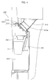
- FIG. 4 is a cross-sectional view illustrating the structure of the ice dispenser 200. More specifically, FIG. 4 is a cross-sectional view schematically illustrating the cross-section of A in the second door 121 illustrated in FIG. 3 . Note that, for description purpose, the illustration of the fourth door 122 is omitted in FIG. 4 .
- the ice dispenser 200 supplies the ice that is made, and includes a supply pipe 210, a lid unit 220, a lever 240, and a serving unit 250.
- the supply pipe 210 forms a path for supplying the ice made by an ice maker (not illustrated) arranged above with the user.
- the supply pipe 210 has a supply opening 210a.
- the supply opening 210a is an opening of the supply pipe 210. More specifically, the supply opening 210a is an outlet for supplying ice. Note that the supply opening 210a may take any shape as long as the supplied ice can pass through.
- the lid unit 220 is a lid covering the supply opening 210a in the supply pipe 210.
- the lid unit 220 includes a shaft 221 and a lid 222.
- the shaft 221 is arranged above the lid 222, and is a rod-shaped shaft for swinging the lid 222. More specifically, the shaft 221 swings the lid 222 around the shaft 221 with the shaft 221 as the center, through the rotation of the shaft 221. Note that, the shaft 221 is preferably arranged above the lid 222, however, it is not limited to the above, and the shaft 221 may be arranged at the center.
- the lid 222 is a tabular portion which rotates around the shaft 221 by the rotation of the shaft 221 for opening and closing the supply opening 210a.
- the lid 222 opens the supply opening 210a by the rotation of the shaft 221 (clockwise rotation in FIG. 4 ) to open the supply opening 210a.
- the lid 222 closes the supply opening 210a by the rotation of the shaft 221 (counterclockwise rotation in FIG. 4 ).
- the lid 222 may take any shape as long as the supply opening 210a can be closed.
- the lever 240 is a switch for rotating the shaft 221 such that the lid 222 opens and closes the supply opening 210a. More specifically, when the user wishes to supply ice into a cup P, the user inserts the cup P into the receiving space 123, and presses the lever 240 in the X direction. In this case, the lower end portion of the lever 240 is pressed into the X direction, the lever 240 swings in the X direction with the top end portion as the center. Furthermore, when the lever 240 swings to a predetermined angle, the lever 240 causes the lid 222 to open the supply opening 210a.
- the lever 240 When the cup P is supplied with ice, and the user took the cup P out of the receiving space 123, the lever 240 is turned back to the original position. Subsequently, when the lever 240 turns back to the original position, the lid 222 closes the supply opening 210a by the lever 240 released from the position at the predetermined angle.
- the serving unit 250 is a part for serving the ice supplied from the supply opening 210a.
- the ice supplied from the serving unit 250 is supplied into the user's cup P.
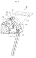
- FIG. 5 is a perspective view illustrating the structure of the ice dispenser 200. Note that, for description purpose, the supply pipe 210 and the cover 300 covering the lid unit 220 and others are illustrated as transparent in dotted lines.
- FIG. 6 is a back perspective view illustrating the ice dispenser 200. More specifically, FIG. 6 is a right-top perspective view of the ice dispenser 200 illustrated in FIG. 5 . Note that, for description purpose, the illustration of the supply pipe 210 is omitted in FIG. 6 .
- the ice dispenser 200 further includes a driver unit 260.
- the driver unit 260 is a driving mechanism for rotating the shaft 221. More specifically, the driver unit 260 swings the lid 222 around the shaft 221 by rotating the shaft 221, and opens and closes the lid 222 with respect to the supply opening 210a.
- the driver unit 260 drives the shaft 221 such that once the lever 240 swings to the predetermined angle; the lid 222 opens the supply opening 210a. Furthermore, the driver unit 260 drives the shaft 221 such that the lid 222 closes the supply opening 210a once the lever 240 is released from the position at the predetermined angle.
- the driver unit 260 fixes the shaft 221 to prevent the rotation of the shaft 221. More specifically, the driver unit 260 includes a gear motor having a worm gear, for example. Accordingly, when the driver unit 260 stops rotation of the shaft 221, the rotation of the shaft 221 is fixed at a position at the time when the driver unit 260 stops, and the position of the lid 222 is fixed.
- FIG. 7 is a functional block diagram illustrating the functional structure for controlling the driver unit 260.
- the refrigerator 100 further includes a control unit 270 for controlling the driver unit 260.
- the control unit 270 is a processing unit for controlling the driver unit 260. More specifically, the control unit 270 drives the driver unit 260 such that the lid 222 opens and closes the supply opening 210a by the swing of the lever 240.
- control unit 270 causes the driver unit 260 to rotate the shaft 221 such that the lid 222 opens the supply opening 210a. Furthermore, the control unit 270 rotates the shaft 221 such that the lid 222 closes the supply opening 210a.
- control unit 270 causes the driver unit 260 to rotate the shaft 221 such that the lid 222 closes the supply opening 210a at a predetermined time interval.
- the predetermined time may be a few minutes or a few hours, and is not particularly limited. However, it is preferable that the predetermined time is a time until the ice stuck between the lid 222 and the supply opening 210a melts.
- FIG. 8 is a perspective view illustrating the external appearance of the lid unit 220.
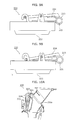
- FIG. 9A and 9B are planar views illustrating the structure of the lid unit 220.
- the lid unit 220 includes, in addition to the shaft 221 and the lid 222, a biasing member 223 and a stopper 224.
- the biasing member 223 is a member for connecting the shaft 221 with the lid 222, and for giving a biasing force to the lid 222 in the closing direction for closing the supply opening 210a. More specifically, an end of the biasing member 223 is fixed to the shaft 221, and the other end of the biasing member 223 is fixed with the lid 222 through the stopper 224. More specifically, the biasing member 223 is a torsion spring.
- the stopper 224 is fixed to the other end of the biasing member 223 and the shaft 221, and is a portion for regulating the swing of the lid 222 around the shaft 221 by the biasing member 223. More specifically, the stopper 224 is arranged such that the lid 222 swings only within the range a illustrated in FIG. 9A .
- a is 5mm, for example.
- FIG. 9A illustrates the lid unit 220 with the lid 222 opening the supply opening 210a
- FIG. 9B illustrates the lid unit 220 with the lid 222 closing the supply opening 210a.
- the biasing member 223 provides a biasing force in the closing direction for causing the lid 222 to close the supply opening 210a (downward in FIG. 9B ).
- FIGS. 10A and 10B are for describing the opening and closing of the lid unit 220. More specifically, FIG. 10A illustrates the open state of the lid unit 220, and FIG. 10B illustrates the closed state of the lid unit 220.
- the lid 222 opens the supply opening 210a by the rotation of the shaft 221 (rotates clockwise in FIG. 10A ) caused by the driving of the driver unit 260 by the control unit 270.
- the biasing member 223 and the stopper 224 in the open state are arranged in a state illustrated in FIG. 9A with respect to the lid 222. More specifically, no biasing force by the biasing member 223 is provided for the lid 222.
- the lid 222 closes the supply opening 210a by the rotation of the shaft 221 (rotates counterclockwise in FIG. 10B ) caused by the driving of the driver unit 260 by the control unit 270.
- the biasing member 223 and the stopper 224 in this closed state are arranged as illustrated in FIG. 9B with respect to the lid 222. More specifically, the biasing member 223 provides a biasing force to the lid 222 in the closing direction for closing the supply opening 210a.
- the lid 222 closes the supply opening 210a with the state illustrated in FIG. 9A by the rotation of the shaft 221. Furthermore, by the rotation of the shaft 221, the stopper 224 swings around the shaft 221, and the biasing member 223 and the stopper 224 are arranged in the state illustrated in FIG. 9B .
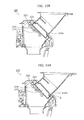
- FIGS. 11A and 11B are for describing the closing of the lid unit 220 when ice is stuck. More specifically, FIG. 11A illustrates the closed state of the lid unit 220 when ice is stuck, and FIG. 11B illustrates the closed state of the lid unit 220 after the ice melts.
- the shaft 221 rotates from the state illustrated in FIG. 10A (rotates counterclockwise in FIG. 11A ). Subsequently, with the ice Q stuck between the lid 222 and the supply opening 210a, the lid 222 closes the supply opening 210a in the state illustrated in FIG. 9A .
- the stopper 224 swings around the shaft 221, and the biasing member 223 and the stopper 224 are arranged in the state illustrated in FIG. 9B . More specifically, the biasing member 223 provides a biasing force to the lid 222 in the closing direction for closing the supply opening 210a.
- the lid 222 closes the supply opening 210a by the biasing member 223. More specifically, by the biasing force in the closing direction to the lid 222 by the biasing member 223 allows the lid 222 to swing around the shaft 221 as the stuck ice Q melts.
- the lid 222 is arranged in the state illustrated in FIG. 9A with respect to the biasing member 223 and the stopper 224, completely closing the supply opening 210a.
- the biasing member 223 provides, to the lid 222, a biasing force in the closing direction for closing the supply opening 210a. Accordingly, even if the ice is stuck between the supply opening 210a and the lid 222, the lid 222 closes the supply opening 210a by the biasing force of the biasing member 223 once the ice melts. Furthermore, here, no electric power for the lid 222 to close the supply opening 210a is necessary.
- the range of swing by the lid 222 is the range a illustrated in FIG. 9A .
- the lid 222 may not be able to completely close the supply opening 210a.
- control unit 270 causes the driver unit 260 to rotate the shaft 221 such that the lid 222 closes the supply opening 210a at a predetermined time interval. This allows the lid 222 to completely close the supply opening 210a.
- the control unit 270 causes the driver unit 260 to rotate the shaft 221 at the predetermined time interval, instead of continuously driving the driver unit 260 to rotate the shaft 221. Therefore, extra power consumption can be suppressed.
- the lid 222 can be completely closed while suppressing extra power consumption.
- the biasing member 223 is a torsion spring.
- the biasing member 223 is not limited to the torsion spring.
- FIG. 12 illustrates a biasing member according to a variation of Embodiment.
- the lid unit 220 includes a biasing member 223a instead of the biasing member 223 illustrated in FIG. 8 .
- the biasing member 223a is a tabular leaf spring. An end of the biasing member 223a is fixed to the shaft 221, and the other end of the biasing member 223a is fixed to the lid 222. With this, the biasing member 223a can provide a biasing force to the lid 222 in the closing direction for closing the supply opening 210a. In this case, as illustrated in FIG. 9A , the swing of the lid 222 is not regulated by the stopper 224. Thus, even when a relatively large ice is stuck, the lid 222 can completely close the supply opening 210a.
- the present invention is applicable to a refrigerator.
Landscapes
- Engineering & Computer Science (AREA)
- Physics & Mathematics (AREA)
- Mechanical Engineering (AREA)
- Thermal Sciences (AREA)
- General Engineering & Computer Science (AREA)
- Refrigerator Housings (AREA)
- Devices That Are Associated With Refrigeration Equipment (AREA)
Abstract
Description
- The present invention relates to refrigerators, and particularly to a refrigerator including an ice dispenser for supplying ice.
- In recent years, refrigerators with ice dispenser for supplying ice are on the market. The ice dispenser includes a supply pipe which serves as a supply path for ice, and a lid for covering a supply opening which is an exit of the supply pipe. The ice dispenser supplies the user with ice made by an ice maker from the supply opening through the supply path in the supply pipe. However, when supplying ice to the user, the lid is sometimes not completely closed because of ice stuck between the supply opening and the lid covering the supply opening.
- In order to solve this problem, an ice dispenser capable of completely closing its lid by delaying the timing for closing the lid so as to prevent the ice from being stuck between the supply opening and the lid has been conventionally proposed (for example, see Patent Literature 1). In this conventional ice dispenser, by delaying the timing for closing the lid, the ice remaining in the supply pipe passes through the supply path and is served from the supply opening. The lid can be fully closed by preventing the ice from remaining in the supply pipe so as to prevent the ice from being stuck between the supply opening and the lid.
-
- [Patent Literature 1] Japanese Unexamined Patent Application Publication No.
H11-287550 - However, although the conventional ice dispenser in a refrigerator prevents the ice from being stuck between the supply opening and the lid, the lid cannot be completely closed when the ice is stuck between the supply opening and the lid.
- In other words, according to the conventional ice dispenser, there is a case in which the ice is stuck between the supply opening and the lid even when the timing for closing the lid is delayed. For example, in the conventional ice dispenser, all of the ice remaining in the supply pipe cannot be served unless the lid closes with timing suitable for the amount of ice remaining in the supply pipe. However, the amount of the ice remaining in the supply pipe is not even, and consequently all of the ice remaining in the supply pipe may not be served, depending on the timing for closing the lid. Furthermore, there is a case in which all of the ice remaining in the supply pipe cannot be served when the ice is stuck in the supply pipe or at the supply opening.
- The lid may not be completely closed due to the ice remaining in the supply pipe stuck between the supply opening and the lid. For example, when a gear motor is used for a driving mechanism for opening and closing the lid, the position of the lid is fixed with the lid not fully closed when the gear motor stops with the ice stuck between the supply opening and the lid. Accordingly, even after the ice melts, the lid is not fully closed, and the lid remains open.
- Alternatively, the lid can be completely closed by driving the gear motor until the ice melts and the lid is fully closed. However, extra power for keep driving the gear motor is necessary.
- The present invention has been conceived in view of these problems, and it is an object of the present invention to provide a refrigerator with an ice dispenser capable of suppressing extra power consumption and fully closing the lid, even when the ice is stuck between the supply opening and the lid.
- In order to achieve the object above, the refrigerator according to the present invention is a refrigerator including an ice dispenser for supplying ice, in which the ice dispenser includes: a supply opening which is an outlet for supplying ice; a lid unit including a shaft and a lid which closes the supply opening through rotation of the shaft; and a driver unit which rotates the shaft, the driver unit fixes the shaft so as to prevent the shaft from rotating, when the driver unit stops the rotation of the shaft, and the lid unit further includes a biasing member which connects the shaft and the lid and provides the lid with a biasing force in a closing direction for closing the supply opening.
- With this, the biasing member provides the lid with the biasing force in the closing direction for closing the supply opening while the driver unit stops and the shaft is fixed. Accordingly, even if the ice is stuck between the supply opening and the lid, the lid closes the supply opening by the biasing force of the biasing member as the ice melts. Furthermore, no electric power for the lid to close the supply opening is required. Thus, even when the ice is stuck between the supply opening and the lid, it is possible to completely close the lid while suppressing extra power consumption.
- Furthermore, it is preferable that a control unit which causes the driver unit to rotate the shaft at a predetermined interval such that the lid closes the supply opening is included.
- With this, the control unit causes the driver unit to rotate the shaft such that the lid closes the supply opening at the predetermined time interval. Here, when a large ice is stuck between the supply opening and the lid, there is a possibility that the lid cannot fully close the supply opening even with the movement of the lid toward the closing direction by the biasing member. In this case, after the large ice melts, the control unit can cause the driver unit to rotate the shaft such that the lid is fully closed. Furthermore, the control unit does not cause the driver unit to keep rotating the shaft, but causes the driver unit to rotate the shaft at the predetermined time interval. Thus, extra electric power consumption is suppressed. Therefore, even when the ice is stuck between the supply opening and the lid, it is possible to completely close the lid while suppressing extra power consumption.
- Note that, the present invention can not only be implemented as a refrigerator having the ice dispenser, but also as an ice dispenser.
- The present invention provides a refrigerator with an ice dispenser capable of completely closing the lid while suppressing the extra power consumption even when the ice is stuck between the supply opening and the lid. Therefore, the present invention is highly practical.
-
- [
FIG. 1] FIG. 1 is a perspective view illustrating an external appearance of a refrigerator. - [
FIG. 2] FIG. 2 is a perspective view illustrating an external appearance of the refrigerator with the third door and the fourth door open. - [
FIG. 3] FIG. 3 is a perspective view illustrating an external appearance of the refrigerator with the first door and the second door open. - [
FIG. 4] FIG. 4 is a cross-sectional view illustrating the structure of an ice dispenser. - [
FIG. 5] FIG. 5 is a perspective view illustrating the structure of the ice dispenser. - [
FIG. 6] FIG. 6 is a back-perspective view of the ice dispenser. - [
FIG. 7] FIG. 7 is a functional block diagram illustrating functional configuration for controlling the driver unit. - [
FIG. 8] FIG. 8 is a perspective view illustrating an external appearance of a lid unit. - [
FIG. 9A] FIG. 9A is a planar view illustrating the structure of the lid unit. - [
FIG. 9B] FIG. 9B is a planar view illustrating the structure of the lid unit. - [
FIG. 10A] FIG. 10A is for describing open-close operation of the lid unit. - [
FIG. 10B] FIG. 10B is for describing open-close operation of the lid unit. - [
FIG. 11A] FIG. 11A is for describing closing operation of the lid unit when ice is stuck. - [
FIG. 11B] FIG. 11B is for describing closing operation of the lid unit when ice is stuck. - [
FIG. 12] FIG. 12 illustrates a biasing member according to a variation of Embodiment. - The following shall describe Embodiment of the refrigerator according to the present invention with reference to the drawings.
-
FIG. 1 is a perspective view illustrating the external appearance of the refrigerator. -
FIG. 2 is a perspective view illustrating the external appearance of the refrigerator with a third door and a fourth door open. - As illustrated in these drawings, the
refrigerator 100 includes a heat-insulatingmain body 150, afirst door 111, asecond door 121, athird door 112, a throughhole 113, afourth door 122, and a receivingspace 123. - The heat-insulating
main body 150 is a box with an opening at the front face, and has a heat-insulating capacity for blocking the exchange of heat between the inside and the outside of therefrigerator 100. - The
first door 111 is a door which freely opens and closes at an opening of the heat-insulating main body on the right of the user when facing the heat-insulatingmain body 150. In this Embodiment, thefirst door 111 is attached to the heat-insulatingmain body 150 by a hinge (not illustrated) such that thefirst door 111 swings around an axis extending in the vertical direction in front of the right side wall of the heat-insulatingmain body 150. Thefirst door 111 is rectangular when viewed from front, and the axis passes through a right end portion of thefirst door 111. - The
second door 121 freely opens and closes at an opening of the heat-insulatingmain body 150 on the left of the user when facing the heat-insulatingmain body 150. In this Embodiment, thesecond door 121 is attached to the heat-insulatingmain body 150 by a hinge (not illustrated) such that thefirst door 111 rotates around an axis extending in the vertical direction in front of the left side wall of the heat-insulatingmain body 150. Thesecond door 121 is rectangular when viewed from front, and the axis passes through a left end portion of thesecond door 121. - The through
hole 113 is a hole through thefirst door 111 in thickness direction. The throughhole 113 is for taking out items stored behind thefirst door 111 and for taking into items behind thefirst door 111 for storage, without opening thefirst door 111. - The
third door 112 is a door which freely opens and closes at the throughhole 113. In this Embodiment, thethird door 112 is attached to thefirst door 111 by a hinge (not illustrated) such that thethird door 112 swings around an axis laterally extending at the lower end portion of the throughhole 113. Thethird door 112 is substantially square-shaped when viewed from front (with rounded corners), and the axis passes through the lower end portion of thethird door 112. - The receiving
space 123 is a space provided inside of thesecond door 121, and is a space for the user to receive ice supplied from an ice dispenser (not illustrated) provided inside of thesecond door 121. At the front face of the receivingspace 123, an opening through the front face of thesecond door 121 in the thickness direction is formed. - More specifically, the
fourth door 122 is a door which freely opens and closes at the front of the receivingspace 123. In this Embodiment, thefourth door 122 is attached to thesecond door 121 by a hinge (not illustrated) such that thefourth door 122 swings around an axis extending laterally at the lower end portion of the front of the receivingspace 123. Thefourth door 122 is substantially square-shaped when viewed from front (with rounded corners), and the axis passes through the lower end portion of thefourth door 122. -
FIG. 3 is a perspective view illustrating the external appearance of the refrigerator with the first door and the second door open. - As illustrated in the drawing, the
refrigerator 100 includes apartition 153. - The
partition 153 is a wall laterally partitioning the inside of the heat-insulatingmain body 150. In this Embodiment, the right side of thepartition 153 inside the heat-insulatingmain body 150 is afirst storage compartment 151, and is a refrigerator compartment. On the other hand, the left side of thepartition 153 inside the heat-insulatingmain body 150 is asecond storage compartment 152, and is a freezer compartment. Thepartition 153 is a wall partitioning the refrigerator compartment and the freezer compartment, and has heat-insulating property. - The ice dispenser for supplying the user with ice made is provided inside the second door 121 (A in
FIG. 3 ) which freely opens and closes at the opening of thesecond storage compartment 152, which is the freezer compartment. - The following shall describe the details of the ice dispenser.
-
FIG. 4 is a cross-sectional view illustrating the structure of theice dispenser 200. More specifically,FIG. 4 is a cross-sectional view schematically illustrating the cross-section of A in thesecond door 121 illustrated inFIG. 3 . Note that, for description purpose, the illustration of thefourth door 122 is omitted inFIG. 4 . - As illustrated in
FIG. 4 , theice dispenser 200 supplies the ice that is made, and includes asupply pipe 210, alid unit 220, alever 240, and a servingunit 250. - The
supply pipe 210 forms a path for supplying the ice made by an ice maker (not illustrated) arranged above with the user. Thesupply pipe 210 has asupply opening 210a. - The
supply opening 210a is an opening of thesupply pipe 210. More specifically, thesupply opening 210a is an outlet for supplying ice. Note that thesupply opening 210a may take any shape as long as the supplied ice can pass through. - The
lid unit 220 is a lid covering thesupply opening 210a in thesupply pipe 210. Thelid unit 220 includes ashaft 221 and alid 222. - The
shaft 221 is arranged above thelid 222, and is a rod-shaped shaft for swinging thelid 222. More specifically, theshaft 221 swings thelid 222 around theshaft 221 with theshaft 221 as the center, through the rotation of theshaft 221. Note that, theshaft 221 is preferably arranged above thelid 222, however, it is not limited to the above, and theshaft 221 may be arranged at the center. - The
lid 222 is a tabular portion which rotates around theshaft 221 by the rotation of theshaft 221 for opening and closing thesupply opening 210a. In other words, thelid 222 opens thesupply opening 210a by the rotation of the shaft 221 (clockwise rotation inFIG. 4 ) to open thesupply opening 210a. Thelid 222 closes thesupply opening 210a by the rotation of the shaft 221 (counterclockwise rotation inFIG. 4 ). Note that, thelid 222 may take any shape as long as thesupply opening 210a can be closed. - The
lever 240 is a switch for rotating theshaft 221 such that thelid 222 opens and closes thesupply opening 210a. More specifically, when the user wishes to supply ice into a cup P, the user inserts the cup P into the receivingspace 123, and presses thelever 240 in the X direction. In this case, the lower end portion of thelever 240 is pressed into the X direction, thelever 240 swings in the X direction with the top end portion as the center. Furthermore, when thelever 240 swings to a predetermined angle, thelever 240 causes thelid 222 to open thesupply opening 210a. - When the cup P is supplied with ice, and the user took the cup P out of the receiving
space 123, thelever 240 is turned back to the original position. Subsequently, when thelever 240 turns back to the original position, thelid 222 closes thesupply opening 210a by thelever 240 released from the position at the predetermined angle. - The serving
unit 250 is a part for serving the ice supplied from thesupply opening 210a. The ice supplied from the servingunit 250 is supplied into the user's cup P. -
FIG. 5 is a perspective view illustrating the structure of theice dispenser 200. Note that, for description purpose, thesupply pipe 210 and thecover 300 covering thelid unit 220 and others are illustrated as transparent in dotted lines. -
FIG. 6 is a back perspective view illustrating theice dispenser 200. More specifically,FIG. 6 is a right-top perspective view of theice dispenser 200 illustrated inFIG. 5 . Note that, for description purpose, the illustration of thesupply pipe 210 is omitted inFIG. 6 . - As illustrated in these drawings, the
ice dispenser 200 further includes adriver unit 260. - The
driver unit 260 is a driving mechanism for rotating theshaft 221. More specifically, thedriver unit 260 swings thelid 222 around theshaft 221 by rotating theshaft 221, and opens and closes thelid 222 with respect to thesupply opening 210a. - More specifically, the
driver unit 260 drives theshaft 221 such that once thelever 240 swings to the predetermined angle; thelid 222 opens thesupply opening 210a. Furthermore, thedriver unit 260 drives theshaft 221 such that thelid 222 closes thesupply opening 210a once thelever 240 is released from the position at the predetermined angle. - Furthermore, when the rotation of the
shaft 221 stops, thedriver unit 260 fixes theshaft 221 to prevent the rotation of theshaft 221. More specifically, thedriver unit 260 includes a gear motor having a worm gear, for example. Accordingly, when thedriver unit 260 stops rotation of theshaft 221, the rotation of theshaft 221 is fixed at a position at the time when thedriver unit 260 stops, and the position of thelid 222 is fixed. -
FIG. 7 is a functional block diagram illustrating the functional structure for controlling thedriver unit 260. - As illustrated in
FIG. 7 , therefrigerator 100 further includes acontrol unit 270 for controlling thedriver unit 260. - The
control unit 270 is a processing unit for controlling thedriver unit 260. More specifically, thecontrol unit 270 drives thedriver unit 260 such that thelid 222 opens and closes thesupply opening 210a by the swing of thelever 240. - More specifically, the
control unit 270 causes thedriver unit 260 to rotate theshaft 221 such that thelid 222 opens thesupply opening 210a. Furthermore, thecontrol unit 270 rotates theshaft 221 such that thelid 222 closes thesupply opening 210a. - Furthermore, the
control unit 270 causes thedriver unit 260 to rotate theshaft 221 such that thelid 222 closes thesupply opening 210a at a predetermined time interval. Here, the predetermined time may be a few minutes or a few hours, and is not particularly limited. However, it is preferable that the predetermined time is a time until the ice stuck between thelid 222 and thesupply opening 210a melts. - Next, the structure of the
lid unit 220 shall be described in detail. -
FIG. 8 is a perspective view illustrating the external appearance of thelid unit 220. -
FIG. 9A and 9B are planar views illustrating the structure of thelid unit 220. - As illustrated in these drawings, the
lid unit 220 includes, in addition to theshaft 221 and thelid 222, a biasingmember 223 and astopper 224. - The biasing
member 223 is a member for connecting theshaft 221 with thelid 222, and for giving a biasing force to thelid 222 in the closing direction for closing thesupply opening 210a. More specifically, an end of the biasingmember 223 is fixed to theshaft 221, and the other end of the biasingmember 223 is fixed with thelid 222 through thestopper 224. More specifically, the biasingmember 223 is a torsion spring. - The
stopper 224 is fixed to the other end of the biasingmember 223 and theshaft 221, and is a portion for regulating the swing of thelid 222 around theshaft 221 by the biasingmember 223. More specifically, thestopper 224 is arranged such that thelid 222 swings only within the range a illustrated inFIG. 9A . Here, a is 5mm, for example. - Here,
FIG. 9A illustrates thelid unit 220 with thelid 222 opening thesupply opening 210a, andFIG. 9B illustrates thelid unit 220 with thelid 222 closing thesupply opening 210a. More specifically, in thelid unit 220 illustrated inFIG. 9B , the biasingmember 223 provides a biasing force in the closing direction for causing thelid 222 to close thesupply opening 210a (downward inFIG. 9B ). - Next, the opening and closing of the
lid unit 220 shall be specifically described. -
FIGS. 10A and10B are for describing the opening and closing of thelid unit 220. More specifically,FIG. 10A illustrates the open state of thelid unit 220, andFIG. 10B illustrates the closed state of thelid unit 220. - First, as illustrated in
FIG. 10A , thelid 222 opens thesupply opening 210a by the rotation of the shaft 221 (rotates clockwise inFIG. 10A ) caused by the driving of thedriver unit 260 by thecontrol unit 270. The biasingmember 223 and thestopper 224 in the open state are arranged in a state illustrated inFIG. 9A with respect to thelid 222. More specifically, no biasing force by the biasingmember 223 is provided for thelid 222. - As illustrated in
FIG. 10B , thelid 222 closes thesupply opening 210a by the rotation of the shaft 221 (rotates counterclockwise inFIG. 10B ) caused by the driving of thedriver unit 260 by thecontrol unit 270. The biasingmember 223 and thestopper 224 in this closed state are arranged as illustrated inFIG. 9B with respect to thelid 222. More specifically, the biasingmember 223 provides a biasing force to thelid 222 in the closing direction for closing thesupply opening 210a. - More specifically, first, from the state illustrated in
FIG. 10A , thelid 222 closes thesupply opening 210a with the state illustrated inFIG. 9A by the rotation of theshaft 221. Furthermore, by the rotation of theshaft 221, thestopper 224 swings around theshaft 221, and the biasingmember 223 and thestopper 224 are arranged in the state illustrated inFIG. 9B . -
FIGS. 11A and11B are for describing the closing of thelid unit 220 when ice is stuck. More specifically,FIG. 11A illustrates the closed state of thelid unit 220 when ice is stuck, andFIG. 11B illustrates the closed state of thelid unit 220 after the ice melts. - First, as illustrated in
FIG. 11A , theshaft 221 rotates from the state illustrated inFIG. 10A (rotates counterclockwise inFIG. 11A ). Subsequently, with the ice Q stuck between thelid 222 and thesupply opening 210a, thelid 222 closes thesupply opening 210a in the state illustrated inFIG. 9A . - Furthermore, by the rotation of the
shaft 221, thestopper 224 swings around theshaft 221, and the biasingmember 223 and thestopper 224 are arranged in the state illustrated inFIG. 9B . More specifically, the biasingmember 223 provides a biasing force to thelid 222 in the closing direction for closing thesupply opening 210a. - Here, even though the ice Q is still stuck between the
lid 222 and thesupply opening 210a, the driving of thedriver unit 260 by thecontrol unit 270 stops in this state. Accordingly, the rotation of theshaft 221 stops at a position with the ice Q stuck. - Next, as illustrated in
FIG. 11B , when the ice Q stuck melts, thelid 222 closes thesupply opening 210a by the biasingmember 223. More specifically, by the biasing force in the closing direction to thelid 222 by the biasingmember 223 allows thelid 222 to swing around theshaft 221 as the stuck ice Q melts. Thelid 222 is arranged in the state illustrated inFIG. 9A with respect to the biasingmember 223 and thestopper 224, completely closing thesupply opening 210a. - As described above, in a state in which the
driver unit 260 stops and theshaft 221 is fixed, the biasingmember 223 provides, to thelid 222, a biasing force in the closing direction for closing thesupply opening 210a. Accordingly, even if the ice is stuck between thesupply opening 210a and thelid 222, thelid 222 closes thesupply opening 210a by the biasing force of the biasingmember 223 once the ice melts. Furthermore, here, no electric power for thelid 222 to close thesupply opening 210a is necessary. - Here, the range of swing by the
lid 222 is the range a illustrated inFIG. 9A . Thus, depending on the size of ice being stuck, thelid 222 may not be able to completely close thesupply opening 210a. - Accordingly, the
control unit 270 causes thedriver unit 260 to rotate theshaft 221 such that thelid 222 closes thesupply opening 210a at a predetermined time interval. This allows thelid 222 to completely close thesupply opening 210a. - The
control unit 270 causes thedriver unit 260 to rotate theshaft 221 at the predetermined time interval, instead of continuously driving thedriver unit 260 to rotate theshaft 221. Therefore, extra power consumption can be suppressed. - Accordingly, even when ice is stuck between the
supply opening 210a and thelid 222, thelid 222 can be completely closed while suppressing extra power consumption. - Although only an exemplary embodiment of the refrigerator according to the present invention have been described in detail above, those skilled in the art will readily appreciate that many modifications are possible in the exemplary embodiments without materially departing from the novel teachings and advantages of this invention.
- Accordingly, all such modifications are intended to be included within the scope of this invention.
- For example, in this Embodiment, the biasing
member 223 is a torsion spring. However, the biasingmember 223 is not limited to the torsion spring. -
FIG. 12 illustrates a biasing member according to a variation of Embodiment. - As illustrated in
FIG. 12 , thelid unit 220 includes a biasingmember 223a instead of the biasingmember 223 illustrated inFIG. 8 . Here, the biasingmember 223a is a tabular leaf spring. An end of the biasingmember 223a is fixed to theshaft 221, and the other end of the biasingmember 223a is fixed to thelid 222. With this, the biasingmember 223a can provide a biasing force to thelid 222 in the closing direction for closing thesupply opening 210a. In this case, as illustrated inFIG. 9A , the swing of thelid 222 is not regulated by thestopper 224. Thus, even when a relatively large ice is stuck, thelid 222 can completely close thesupply opening 210a. - The present invention is applicable to a refrigerator.
-
- 100 Refrigerator
- 111 First door
- 112 Third door
- 113 Through hole
- 121 Second door
- 122 Fourth door
- 123 Receiving space
- 150 Heat-insulating main body
- 151 First storage compartment
- 152 Second storage compartment
- 153 Partition
- 200 Ice dispenser
- 210 Supply pipe
- 210a Supply opening
- 220 Lid unit
- 221 Shaft
- 222 Lid
- 223 Biasing member
- 224 Stopper
- 240 Lever
- 250 Serving unit
- 260 Driver unit
- 270 Control unit
- 300 Cover
Claims (3)
- A refrigerator comprising
an ice dispenser for supplying ice,
wherein said ice dispenser includes:a supply opening which is an outlet for supplying ice;a lid unit including a shaft and a lid which closes said supply opening through rotation of said shaft; anda driver unit configured to rotate said shaft,said driver unit fixes said shaft so as to prevent said shaft from rotating, when said driver unit stops the rotation of said shaft, andsaid lid unit further includes a biasing member which connects said shaft and said lid and provides said lid with a biasing force in a closing direction for closing said supply opening. - The refrigerator according to Claim 1, further comprising
a control unit configured to cause said driver unit to rotate said shaft at a predetermined interval such that said lid closes said supply opening. - An ice dispenser for supplying ice, comprising:a supply opening which is an outlet for supplying ice;a lid unit including a shaft and a lid which closes said supply opening through rotation of said shaft; anda driver unit configured to rotate said shaft,wherein said driver unit fixes said shaft so as to prevent said shaft from rotating, when said driver unit stops the rotation of said shaft, andsaid lid unit further includes a biasing member which connects said shaft and said lid and provides said lid with a biasing force in a closing direction for closing said supply opening.
Applications Claiming Priority (2)
| Application Number | Priority Date | Filing Date | Title |
|---|---|---|---|
| JP2009052696A JP2010203741A (en) | 2009-03-05 | 2009-03-05 | Refrigerator |
| PCT/JP2010/001441 WO2010100908A1 (en) | 2009-03-05 | 2010-03-03 | Refrigerator |
Publications (3)
| Publication Number | Publication Date |
|---|---|
| EP2405213A1 true EP2405213A1 (en) | 2012-01-11 |
| EP2405213A4 EP2405213A4 (en) | 2014-12-03 |
| EP2405213B1 EP2405213B1 (en) | 2018-12-05 |
Family
ID=42709475
Family Applications (1)
| Application Number | Title | Priority Date | Filing Date |
|---|---|---|---|
| EP10748507.0A Not-in-force EP2405213B1 (en) | 2009-03-05 | 2010-03-03 | Ice dispenser |
Country Status (4)
| Country | Link |
|---|---|
| EP (1) | EP2405213B1 (en) |
| JP (1) | JP2010203741A (en) |
| CN (1) | CN102341662B (en) |
| WO (1) | WO2010100908A1 (en) |
Families Citing this family (3)
| Publication number | Priority date | Publication date | Assignee | Title |
|---|---|---|---|---|
| KR101383902B1 (en) * | 2012-05-17 | 2014-04-10 | 주식회사 교원 | Water purifier having an ice-outlet with a dual cover |
| CN113758096B (en) * | 2021-09-24 | 2022-12-13 | Tcl家用电器(合肥)有限公司 | Ice making device and refrigerator |
| CN117308475A (en) * | 2022-06-21 | 2023-12-29 | 重庆海尔制冷电器有限公司 | refrigerator |
Family Cites Families (10)
| Publication number | Priority date | Publication date | Assignee | Title |
|---|---|---|---|---|
| US3942334A (en) * | 1975-01-08 | 1976-03-09 | Amana Refrigeration, Inc. | Door delay closing mechanism for the ice chute from a power driven ice dispenser in a freezer-refrigerator |
| US4089436A (en) * | 1976-08-26 | 1978-05-16 | Whirlpool Corporation | Refrigerator ice door mechanism |
| US4462437A (en) * | 1981-12-09 | 1984-07-31 | General Electric Company | Door control device with closure regulator |
| US4901396A (en) * | 1988-01-29 | 1990-02-20 | Hoshizaki Electric Co., Ltd. | Ice discharge apparatus of ice dispenser |
| NZ248935A (en) * | 1992-11-02 | 1995-10-26 | White Consolidated Ind Inc | Refrigerator door ice dispenser: actuator dimensioned to accommodate polystyrene cup |
| JP3112450B2 (en) | 1998-03-03 | 2000-11-27 | 三星電子株式会社 | Refrigerator ice dispenser |
| KR200170259Y1 (en) * | 1999-09-03 | 2000-02-15 | 삼성전자주식회사 | Opening and closing device for ice discharge port of refrigerator |
| JP2006084157A (en) * | 2004-09-17 | 2006-03-30 | Hoshizaki Electric Co Ltd | Dispenser |
| KR100835183B1 (en) * | 2006-08-30 | 2008-06-04 | 엘지전자 주식회사 | Refrigerator |
| KR101275560B1 (en) * | 2006-09-05 | 2013-06-20 | 엘지전자 주식회사 | Refrigerator |
-
2009
- 2009-03-05 JP JP2009052696A patent/JP2010203741A/en active Pending
-
2010
- 2010-03-03 WO PCT/JP2010/001441 patent/WO2010100908A1/en not_active Ceased
- 2010-03-03 EP EP10748507.0A patent/EP2405213B1/en not_active Not-in-force
- 2010-03-03 CN CN201080010444.3A patent/CN102341662B/en not_active Expired - Fee Related
Also Published As
| Publication number | Publication date |
|---|---|
| CN102341662A (en) | 2012-02-01 |
| WO2010100908A1 (en) | 2010-09-10 |
| CN102341662B (en) | 2014-01-08 |
| JP2010203741A (en) | 2010-09-16 |
| EP2405213A4 (en) | 2014-12-03 |
| EP2405213B1 (en) | 2018-12-05 |
Similar Documents
| Publication | Publication Date | Title |
|---|---|---|
| US8875538B2 (en) | Refrigerator | |
| EP2940411B1 (en) | Refrigerator | |
| US7866181B2 (en) | Refrigerator with ice-making unit | |
| CN101490486B (en) | Ice making device and refrigerator including same | |
| EP3008268B1 (en) | Fixing device | |
| EP2405215A1 (en) | Refrigerator | |
| US20100313593A1 (en) | Refrigerator and apparatus for ice discharging therein | |
| US8893523B2 (en) | Method of operating a refrigerator | |
| US9974398B2 (en) | Door closer mechanism for display case | |
| CN101490488B (en) | Ice making apparatus and refregerator comprising the same | |
| KR200170259Y1 (en) | Opening and closing device for ice discharge port of refrigerator | |
| EP2381196A3 (en) | Refrigerator with supercooled beverage dispenser and method for controlling the same | |
| WO2012023717A3 (en) | Refrigerator | |
| EP2405213B1 (en) | Ice dispenser | |
| US9004325B2 (en) | Domestic refrigerator including an ice dispenser | |
| EP2024697B1 (en) | Refrigerator | |
| KR20090004162A (en) | Food storage device | |
| WO2015078316A1 (en) | Gate bidirectional-opening apparatus and refrigerator provided with apparatus | |
| KR100871269B1 (en) | Ice maker and refrigerator including same | |
| US20070256442A1 (en) | Motorized ice dispenser door | |
| CN108413667A (en) | A kind of refrigerator trash ice structure and with its refrigerator | |
| CN102369406A (en) | Household refrigerator comprising a water and/or ice dispenser | |
| WO2018003170A1 (en) | Beverage supply device and door structure | |
| RU2010125997A (en) | REFRIGERATING UNIT | |
| JP2018003442A (en) | Door structure |
Legal Events
| Date | Code | Title | Description |
|---|---|---|---|
| PUAI | Public reference made under article 153(3) epc to a published international application that has entered the european phase |
Free format text: ORIGINAL CODE: 0009012 |
|
| 17P | Request for examination filed |
Effective date: 20111005 |
|
| AK | Designated contracting states |
Kind code of ref document: A1 Designated state(s): AT BE BG CH CY CZ DE DK EE ES FI FR GB GR HR HU IE IS IT LI LT LU LV MC MK MT NL NO PL PT RO SE SI SK SM TR |
|
| DAX | Request for extension of the european patent (deleted) | ||
| A4 | Supplementary search report drawn up and despatched |
Effective date: 20141104 |
|
| RIC1 | Information provided on ipc code assigned before grant |
Ipc: F25C 5/00 20060101AFI20141029BHEP |
|
| STAA | Information on the status of an ep patent application or granted ep patent |
Free format text: STATUS: EXAMINATION IS IN PROGRESS |
|
| 17Q | First examination report despatched |
Effective date: 20170919 |
|
| REG | Reference to a national code |
Ref country code: DE Ref legal event code: R079 Ref document number: 602010055612 Country of ref document: DE Free format text: PREVIOUS MAIN CLASS: F25C0005000000 Ipc: F25C0005200000 |
|
| GRAP | Despatch of communication of intention to grant a patent |
Free format text: ORIGINAL CODE: EPIDOSNIGR1 |
|
| STAA | Information on the status of an ep patent application or granted ep patent |
Free format text: STATUS: GRANT OF PATENT IS INTENDED |
|
| RIC1 | Information provided on ipc code assigned before grant |
Ipc: F25C 5/20 20180101AFI20180525BHEP |
|
| INTG | Intention to grant announced |
Effective date: 20180615 |
|
| GRAS | Grant fee paid |
Free format text: ORIGINAL CODE: EPIDOSNIGR3 |
|
| GRAA | (expected) grant |
Free format text: ORIGINAL CODE: 0009210 |
|
| GRAA | (expected) grant |
Free format text: ORIGINAL CODE: 0009210 |
|
| STAA | Information on the status of an ep patent application or granted ep patent |
Free format text: STATUS: THE PATENT HAS BEEN GRANTED |
|
| AK | Designated contracting states |
Kind code of ref document: B1 Designated state(s): AT BE BG CH CY CZ DE DK EE ES FI FR GB GR HR HU IE IS IT LI LT LU LV MC MK MT NL NO PL PT RO SE SI SK SM TR |
|
| REG | Reference to a national code |
Ref country code: GB Ref legal event code: FG4D |
|
| REG | Reference to a national code |
Ref country code: CH Ref legal event code: EP |
|
| REG | Reference to a national code |
Ref country code: AT Ref legal event code: REF Ref document number: 1073567 Country of ref document: AT Kind code of ref document: T Effective date: 20181215 |
|
| REG | Reference to a national code |
Ref country code: IE Ref legal event code: FG4D |
|
| REG | Reference to a national code |
Ref country code: DE Ref legal event code: R096 Ref document number: 602010055612 Country of ref document: DE |
|
| REG | Reference to a national code |
Ref country code: NL Ref legal event code: MP Effective date: 20181205 |
|
| REG | Reference to a national code |
Ref country code: AT Ref legal event code: MK05 Ref document number: 1073567 Country of ref document: AT Kind code of ref document: T Effective date: 20181205 |
|
| REG | Reference to a national code |
Ref country code: LT Ref legal event code: MG4D |
|
| PG25 | Lapsed in a contracting state [announced via postgrant information from national office to epo] |
Ref country code: ES Free format text: LAPSE BECAUSE OF FAILURE TO SUBMIT A TRANSLATION OF THE DESCRIPTION OR TO PAY THE FEE WITHIN THE PRESCRIBED TIME-LIMIT Effective date: 20181205 Ref country code: NO Free format text: LAPSE BECAUSE OF FAILURE TO SUBMIT A TRANSLATION OF THE DESCRIPTION OR TO PAY THE FEE WITHIN THE PRESCRIBED TIME-LIMIT Effective date: 20190305 Ref country code: HR Free format text: LAPSE BECAUSE OF FAILURE TO SUBMIT A TRANSLATION OF THE DESCRIPTION OR TO PAY THE FEE WITHIN THE PRESCRIBED TIME-LIMIT Effective date: 20181205 Ref country code: LT Free format text: LAPSE BECAUSE OF FAILURE TO SUBMIT A TRANSLATION OF THE DESCRIPTION OR TO PAY THE FEE WITHIN THE PRESCRIBED TIME-LIMIT Effective date: 20181205 Ref country code: BG Free format text: LAPSE BECAUSE OF FAILURE TO SUBMIT A TRANSLATION OF THE DESCRIPTION OR TO PAY THE FEE WITHIN THE PRESCRIBED TIME-LIMIT Effective date: 20190305 Ref country code: AT Free format text: LAPSE BECAUSE OF FAILURE TO SUBMIT A TRANSLATION OF THE DESCRIPTION OR TO PAY THE FEE WITHIN THE PRESCRIBED TIME-LIMIT Effective date: 20181205 Ref country code: FI Free format text: LAPSE BECAUSE OF FAILURE TO SUBMIT A TRANSLATION OF THE DESCRIPTION OR TO PAY THE FEE WITHIN THE PRESCRIBED TIME-LIMIT Effective date: 20181205 Ref country code: LV Free format text: LAPSE BECAUSE OF FAILURE TO SUBMIT A TRANSLATION OF THE DESCRIPTION OR TO PAY THE FEE WITHIN THE PRESCRIBED TIME-LIMIT Effective date: 20181205 |
|
| PG25 | Lapsed in a contracting state [announced via postgrant information from national office to epo] |
Ref country code: SE Free format text: LAPSE BECAUSE OF FAILURE TO SUBMIT A TRANSLATION OF THE DESCRIPTION OR TO PAY THE FEE WITHIN THE PRESCRIBED TIME-LIMIT Effective date: 20181205 Ref country code: GR Free format text: LAPSE BECAUSE OF FAILURE TO SUBMIT A TRANSLATION OF THE DESCRIPTION OR TO PAY THE FEE WITHIN THE PRESCRIBED TIME-LIMIT Effective date: 20190306 |
|
| PG25 | Lapsed in a contracting state [announced via postgrant information from national office to epo] |
Ref country code: NL Free format text: LAPSE BECAUSE OF FAILURE TO SUBMIT A TRANSLATION OF THE DESCRIPTION OR TO PAY THE FEE WITHIN THE PRESCRIBED TIME-LIMIT Effective date: 20181205 |
|
| PG25 | Lapsed in a contracting state [announced via postgrant information from national office to epo] |
Ref country code: IT Free format text: LAPSE BECAUSE OF FAILURE TO SUBMIT A TRANSLATION OF THE DESCRIPTION OR TO PAY THE FEE WITHIN THE PRESCRIBED TIME-LIMIT Effective date: 20181205 Ref country code: PL Free format text: LAPSE BECAUSE OF FAILURE TO SUBMIT A TRANSLATION OF THE DESCRIPTION OR TO PAY THE FEE WITHIN THE PRESCRIBED TIME-LIMIT Effective date: 20181205 Ref country code: CZ Free format text: LAPSE BECAUSE OF FAILURE TO SUBMIT A TRANSLATION OF THE DESCRIPTION OR TO PAY THE FEE WITHIN THE PRESCRIBED TIME-LIMIT Effective date: 20181205 Ref country code: PT Free format text: LAPSE BECAUSE OF FAILURE TO SUBMIT A TRANSLATION OF THE DESCRIPTION OR TO PAY THE FEE WITHIN THE PRESCRIBED TIME-LIMIT Effective date: 20190405 |
|
| PG25 | Lapsed in a contracting state [announced via postgrant information from national office to epo] |
Ref country code: SM Free format text: LAPSE BECAUSE OF FAILURE TO SUBMIT A TRANSLATION OF THE DESCRIPTION OR TO PAY THE FEE WITHIN THE PRESCRIBED TIME-LIMIT Effective date: 20181205 Ref country code: EE Free format text: LAPSE BECAUSE OF FAILURE TO SUBMIT A TRANSLATION OF THE DESCRIPTION OR TO PAY THE FEE WITHIN THE PRESCRIBED TIME-LIMIT Effective date: 20181205 Ref country code: RO Free format text: LAPSE BECAUSE OF FAILURE TO SUBMIT A TRANSLATION OF THE DESCRIPTION OR TO PAY THE FEE WITHIN THE PRESCRIBED TIME-LIMIT Effective date: 20181205 Ref country code: IS Free format text: LAPSE BECAUSE OF FAILURE TO SUBMIT A TRANSLATION OF THE DESCRIPTION OR TO PAY THE FEE WITHIN THE PRESCRIBED TIME-LIMIT Effective date: 20190405 Ref country code: SK Free format text: LAPSE BECAUSE OF FAILURE TO SUBMIT A TRANSLATION OF THE DESCRIPTION OR TO PAY THE FEE WITHIN THE PRESCRIBED TIME-LIMIT Effective date: 20181205 |
|
| REG | Reference to a national code |
Ref country code: DE Ref legal event code: R097 Ref document number: 602010055612 Country of ref document: DE |
|
| PLBE | No opposition filed within time limit |
Free format text: ORIGINAL CODE: 0009261 |
|
| STAA | Information on the status of an ep patent application or granted ep patent |
Free format text: STATUS: NO OPPOSITION FILED WITHIN TIME LIMIT |
|
| PG25 | Lapsed in a contracting state [announced via postgrant information from national office to epo] |
Ref country code: DK Free format text: LAPSE BECAUSE OF FAILURE TO SUBMIT A TRANSLATION OF THE DESCRIPTION OR TO PAY THE FEE WITHIN THE PRESCRIBED TIME-LIMIT Effective date: 20181205 Ref country code: MC Free format text: LAPSE BECAUSE OF FAILURE TO SUBMIT A TRANSLATION OF THE DESCRIPTION OR TO PAY THE FEE WITHIN THE PRESCRIBED TIME-LIMIT Effective date: 20181205 Ref country code: SI Free format text: LAPSE BECAUSE OF FAILURE TO SUBMIT A TRANSLATION OF THE DESCRIPTION OR TO PAY THE FEE WITHIN THE PRESCRIBED TIME-LIMIT Effective date: 20181205 |
|
| REG | Reference to a national code |
Ref country code: CH Ref legal event code: PL |
|
| 26N | No opposition filed |
Effective date: 20190906 |
|
| GBPC | Gb: european patent ceased through non-payment of renewal fee |
Effective date: 20190305 |
|
| PG25 | Lapsed in a contracting state [announced via postgrant information from national office to epo] |
Ref country code: LU Free format text: LAPSE BECAUSE OF NON-PAYMENT OF DUE FEES Effective date: 20190303 |
|
| REG | Reference to a national code |
Ref country code: BE Ref legal event code: MM Effective date: 20190331 |
|
| PG25 | Lapsed in a contracting state [announced via postgrant information from national office to epo] |
Ref country code: GB Free format text: LAPSE BECAUSE OF NON-PAYMENT OF DUE FEES Effective date: 20190305 Ref country code: IE Free format text: LAPSE BECAUSE OF NON-PAYMENT OF DUE FEES Effective date: 20190303 Ref country code: LI Free format text: LAPSE BECAUSE OF NON-PAYMENT OF DUE FEES Effective date: 20190331 Ref country code: CH Free format text: LAPSE BECAUSE OF NON-PAYMENT OF DUE FEES Effective date: 20190331 |
|
| PG25 | Lapsed in a contracting state [announced via postgrant information from national office to epo] |
Ref country code: FR Free format text: LAPSE BECAUSE OF NON-PAYMENT OF DUE FEES Effective date: 20190331 Ref country code: BE Free format text: LAPSE BECAUSE OF NON-PAYMENT OF DUE FEES Effective date: 20190331 |
|
| PG25 | Lapsed in a contracting state [announced via postgrant information from national office to epo] |
Ref country code: TR Free format text: LAPSE BECAUSE OF FAILURE TO SUBMIT A TRANSLATION OF THE DESCRIPTION OR TO PAY THE FEE WITHIN THE PRESCRIBED TIME-LIMIT Effective date: 20181205 |
|
| PGFP | Annual fee paid to national office [announced via postgrant information from national office to epo] |
Ref country code: DE Payment date: 20200320 Year of fee payment: 11 |
|
| PG25 | Lapsed in a contracting state [announced via postgrant information from national office to epo] |
Ref country code: MT Free format text: LAPSE BECAUSE OF NON-PAYMENT OF DUE FEES Effective date: 20190303 |
|
| PG25 | Lapsed in a contracting state [announced via postgrant information from national office to epo] |
Ref country code: CY Free format text: LAPSE BECAUSE OF FAILURE TO SUBMIT A TRANSLATION OF THE DESCRIPTION OR TO PAY THE FEE WITHIN THE PRESCRIBED TIME-LIMIT Effective date: 20181205 |
|
| PG25 | Lapsed in a contracting state [announced via postgrant information from national office to epo] |
Ref country code: HU Free format text: LAPSE BECAUSE OF FAILURE TO SUBMIT A TRANSLATION OF THE DESCRIPTION OR TO PAY THE FEE WITHIN THE PRESCRIBED TIME-LIMIT; INVALID AB INITIO Effective date: 20100303 |
|
| REG | Reference to a national code |
Ref country code: DE Ref legal event code: R119 Ref document number: 602010055612 Country of ref document: DE |
|
| PG25 | Lapsed in a contracting state [announced via postgrant information from national office to epo] |
Ref country code: DE Free format text: LAPSE BECAUSE OF NON-PAYMENT OF DUE FEES Effective date: 20211001 |
|
| PG25 | Lapsed in a contracting state [announced via postgrant information from national office to epo] |
Ref country code: MK Free format text: LAPSE BECAUSE OF FAILURE TO SUBMIT A TRANSLATION OF THE DESCRIPTION OR TO PAY THE FEE WITHIN THE PRESCRIBED TIME-LIMIT Effective date: 20181205 |