EP2405180A2 - Intrinsically safe flashlight - Google Patents
Intrinsically safe flashlight Download PDFInfo
- Publication number
- EP2405180A2 EP2405180A2 EP11183839A EP11183839A EP2405180A2 EP 2405180 A2 EP2405180 A2 EP 2405180A2 EP 11183839 A EP11183839 A EP 11183839A EP 11183839 A EP11183839 A EP 11183839A EP 2405180 A2 EP2405180 A2 EP 2405180A2
- Authority
- EP
- European Patent Office
- Prior art keywords
- flashlight
- intrinsically safe
- light emitting
- battery
- batteries
- Prior art date
- Legal status (The legal status is an assumption and is not a legal conclusion. Google has not performed a legal analysis and makes no representation as to the accuracy of the status listed.)
- Withdrawn
Links
- 231100001261 hazardous Toxicity 0.000 claims abstract description 20
- 239000007789 gas Substances 0.000 claims description 6
- 239000007788 liquid Substances 0.000 claims description 4
- 239000003990 capacitor Substances 0.000 description 32
- 238000000034 method Methods 0.000 description 21
- 239000000463 material Substances 0.000 description 7
- 239000000203 mixture Substances 0.000 description 5
- 238000004880 explosion Methods 0.000 description 4
- 230000000694 effects Effects 0.000 description 3
- 238000010926 purge Methods 0.000 description 3
- 239000004065 semiconductor Substances 0.000 description 3
- -1 Nickel Metal Hydride Chemical class 0.000 description 2
- 230000004075 alteration Effects 0.000 description 2
- 230000015556 catabolic process Effects 0.000 description 2
- 238000006243 chemical reaction Methods 0.000 description 2
- 238000010586 diagram Methods 0.000 description 2
- 230000009429 distress Effects 0.000 description 2
- 238000004146 energy storage Methods 0.000 description 2
- 238000005286 illumination Methods 0.000 description 2
- 229910001416 lithium ion Inorganic materials 0.000 description 2
- 238000012423 maintenance Methods 0.000 description 2
- 238000012986 modification Methods 0.000 description 2
- 230000004048 modification Effects 0.000 description 2
- 230000008439 repair process Effects 0.000 description 2
- HBBGRARXTFLTSG-UHFFFAOYSA-N Lithium ion Chemical compound [Li+] HBBGRARXTFLTSG-UHFFFAOYSA-N 0.000 description 1
- GPVWCGHDIGTNCE-UHFFFAOYSA-N [Fe](=S)=S.[Li] Chemical compound [Fe](=S)=S.[Li] GPVWCGHDIGTNCE-UHFFFAOYSA-N 0.000 description 1
- 230000008901 benefit Effects 0.000 description 1
- 230000033228 biological regulation Effects 0.000 description 1
- OJIJEKBXJYRIBZ-UHFFFAOYSA-N cadmium nickel Chemical compound [Ni].[Cd] OJIJEKBXJYRIBZ-UHFFFAOYSA-N 0.000 description 1
- 239000003985 ceramic capacitor Substances 0.000 description 1
- 230000008859 change Effects 0.000 description 1
- 239000003086 colorant Substances 0.000 description 1
- 230000007423 decrease Effects 0.000 description 1
- 238000005516 engineering process Methods 0.000 description 1
- 239000002360 explosive Substances 0.000 description 1
- 229910052736 halogen Inorganic materials 0.000 description 1
- 150000002367 halogens Chemical class 0.000 description 1
- 230000001939 inductive effect Effects 0.000 description 1
- 229910052743 krypton Inorganic materials 0.000 description 1
- DNNSSWSSYDEUBZ-UHFFFAOYSA-N krypton atom Chemical compound [Kr] DNNSSWSSYDEUBZ-UHFFFAOYSA-N 0.000 description 1
- 229910052960 marcasite Inorganic materials 0.000 description 1
- 238000005259 measurement Methods 0.000 description 1
- 229910052987 metal hydride Inorganic materials 0.000 description 1
- 229910052759 nickel Inorganic materials 0.000 description 1
- PXHVJJICTQNCMI-UHFFFAOYSA-N nickel Substances [Ni] PXHVJJICTQNCMI-UHFFFAOYSA-N 0.000 description 1
- 230000001681 protective effect Effects 0.000 description 1
- 229910052683 pyrite Inorganic materials 0.000 description 1
- NIFIFKQPDTWWGU-UHFFFAOYSA-N pyrite Chemical compound [Fe+2].[S-][S-] NIFIFKQPDTWWGU-UHFFFAOYSA-N 0.000 description 1
- 230000001105 regulatory effect Effects 0.000 description 1
- 238000009877 rendering Methods 0.000 description 1
- 238000012360 testing method Methods 0.000 description 1
- 229910052724 xenon Inorganic materials 0.000 description 1
- FHNFHKCVQCLJFQ-UHFFFAOYSA-N xenon atom Chemical compound [Xe] FHNFHKCVQCLJFQ-UHFFFAOYSA-N 0.000 description 1
Images



Classifications
-
- F—MECHANICAL ENGINEERING; LIGHTING; HEATING; WEAPONS; BLASTING
- F21—LIGHTING
- F21L—LIGHTING DEVICES OR SYSTEMS THEREOF, BEING PORTABLE OR SPECIALLY ADAPTED FOR TRANSPORTATION
- F21L4/00—Electric lighting devices with self-contained electric batteries or cells
- F21L4/005—Electric lighting devices with self-contained electric batteries or cells the device being a pocket lamp
-
- F—MECHANICAL ENGINEERING; LIGHTING; HEATING; WEAPONS; BLASTING
- F21—LIGHTING
- F21L—LIGHTING DEVICES OR SYSTEMS THEREOF, BEING PORTABLE OR SPECIALLY ADAPTED FOR TRANSPORTATION
- F21L4/00—Electric lighting devices with self-contained electric batteries or cells
- F21L4/02—Electric lighting devices with self-contained electric batteries or cells characterised by the provision of two or more light sources
- F21L4/022—Pocket lamps
- F21L4/027—Pocket lamps the light sources being a LED
-
- F—MECHANICAL ENGINEERING; LIGHTING; HEATING; WEAPONS; BLASTING
- F21—LIGHTING
- F21V—FUNCTIONAL FEATURES OR DETAILS OF LIGHTING DEVICES OR SYSTEMS THEREOF; STRUCTURAL COMBINATIONS OF LIGHTING DEVICES WITH OTHER ARTICLES, NOT OTHERWISE PROVIDED FOR
- F21V25/00—Safety devices structurally associated with lighting devices
- F21V25/12—Flameproof or explosion-proof arrangements
-
- H—ELECTRICITY
- H05—ELECTRIC TECHNIQUES NOT OTHERWISE PROVIDED FOR
- H05B—ELECTRIC HEATING; ELECTRIC LIGHT SOURCES NOT OTHERWISE PROVIDED FOR; CIRCUIT ARRANGEMENTS FOR ELECTRIC LIGHT SOURCES, IN GENERAL
- H05B45/00—Circuit arrangements for operating light-emitting diodes [LED]
- H05B45/30—Driver circuits
- H05B45/37—Converter circuits
-
- H—ELECTRICITY
- H05—ELECTRIC TECHNIQUES NOT OTHERWISE PROVIDED FOR
- H05B—ELECTRIC HEATING; ELECTRIC LIGHT SOURCES NOT OTHERWISE PROVIDED FOR; CIRCUIT ARRANGEMENTS FOR ELECTRIC LIGHT SOURCES, IN GENERAL
- H05B45/00—Circuit arrangements for operating light-emitting diodes [LED]
- H05B45/30—Driver circuits
- H05B45/37—Converter circuits
- H05B45/3725—Switched mode power supply [SMPS]
-
- F—MECHANICAL ENGINEERING; LIGHTING; HEATING; WEAPONS; BLASTING
- F21—LIGHTING
- F21Y—INDEXING SCHEME ASSOCIATED WITH SUBCLASSES F21K, F21L, F21S and F21V, RELATING TO THE FORM OR THE KIND OF THE LIGHT SOURCES OR OF THE COLOUR OF THE LIGHT EMITTED
- F21Y2115/00—Light-generating elements of semiconductor light sources
- F21Y2115/10—Light-emitting diodes [LED]
-
- H—ELECTRICITY
- H05—ELECTRIC TECHNIQUES NOT OTHERWISE PROVIDED FOR
- H05B—ELECTRIC HEATING; ELECTRIC LIGHT SOURCES NOT OTHERWISE PROVIDED FOR; CIRCUIT ARRANGEMENTS FOR ELECTRIC LIGHT SOURCES, IN GENERAL
- H05B45/00—Circuit arrangements for operating light-emitting diodes [LED]
- H05B45/30—Driver circuits
- H05B45/37—Converter circuits
- H05B45/3725—Switched mode power supply [SMPS]
- H05B45/38—Switched mode power supply [SMPS] using boost topology
-
- Y—GENERAL TAGGING OF NEW TECHNOLOGICAL DEVELOPMENTS; GENERAL TAGGING OF CROSS-SECTIONAL TECHNOLOGIES SPANNING OVER SEVERAL SECTIONS OF THE IPC; TECHNICAL SUBJECTS COVERED BY FORMER USPC CROSS-REFERENCE ART COLLECTIONS [XRACs] AND DIGESTS
- Y10—TECHNICAL SUBJECTS COVERED BY FORMER USPC
- Y10S—TECHNICAL SUBJECTS COVERED BY FORMER USPC CROSS-REFERENCE ART COLLECTIONS [XRACs] AND DIGESTS
- Y10S362/00—Illumination
- Y10S362/80—Light emitting diode
Definitions
- the present application relates to portable, battery powered light sources for use in hazardous locations. While it finds particular application to intrinsically safe flashlights, the application also relates to other portable and hand-held lighting devices suitable for use in environments which present a risk of fire or explosion.
- Hazardous (classified) locations include those locations in which ignitable concentrations of flammable or combustible materials are or may reasonably be expected to be present in the atmosphere. Such conditions are sometimes encountered in mines, refineries, and other industrial environments in flammable or combustible atmospheres may be present.
- purging in which an enclosure is supplied with a protective gas at a sufficient flow and positive pressure to reduce the concentration of a flammable material to an acceptable level.
- purging systems can be relatively complex, and a source of purge gas may not readily available.
- One intrinsically safe flashlight has included three (3) light emitting diodes (LEDs) each having a nominal forward voltage of about 3.6 volts direct current (VDC).
- the flashlight has been powered by three (3) 1.5 VDC Type N batteries, with an energy limiting resistor disposed electrically in series between the batteries and the LEDs.
- a particular disadvantage of such a configuration is that three (3) batteries are required to supply the nominal 3.6VDC forward voltage of the LEDs.
- a still further disadvantage is that the current supplied to the LEDs is a function of the battery voltage, the LED forward voltage, and the series resistance. As a result, the intensity of the light produced by the flashlight can vary significantly as the batteries discharge.
- such a configuration utilizes the energy from the batteries relatively inefficiently, so that the flashlight is relatively bulky for a given light output and operating time.
- an intrinsically safe, battery powered flashlight includes a first light source, a battery receiving region, and an intrinsically safe, active electrical circuit which uses energy from a battery received in the battery receiving region to power the light source.
- a method includes receiving electrical energy from a battery disposed in a battery receiving region of a flashlight and using an intrinsically safe active electrical circuit to supply electrical energy received from the battery to a first light source of the flashlight.
- a human-portable lighting apparatus includes a battery receiving region adapted to receive at least a first battery, a user operable control, a light emitting diode light source, and an intrinsically safe, closed loop control circuit means operatively connected to the user control for using energy from the at least a first battery to selectively. power the light source.
- the flashlight 100 also includes a light management system such as a generally parabolic reflector 112 and lens 114, a circuit board 116, and a light source 118 such as one or more light emitting diodes (LEDs) which, as illustrated, are carried by the second end cap 106.
- a user-operable switch 120 such as a pushbutton on/off switch allows a user to control the operation of the flashlight 100 as desired. As illustrated in Figure 1 , the switch 120 is actuated through a flexible switch cover 122.
- the batteries 110, switch 120 and circuit board 116 configured as an intrinsically safe electrical circuit suitable for use in hazardous locations and through which energy from the batteries 110 is used to selectively illuminate the light source 118.
- an energy limiter such as a fuse F 1 and a current limiting resistor R L are disposed electrically in series between the batteries 110 and the input V in of the converter circuit 202.
- the fuse F 1 and current limiting resistor R L cooperate to limit the available energy so that any spark or thermal effect produced during normal operation or under fault conditions is incapable of causing ignition of a mixture of a flammable or combustible material in air in the mixture's most easily ignitable concentration.
- the energy limiter should be located as near as practicable to the battery receiving region 108, and the requisite electrical connections 124 should be suitably spaced and insulated so as prevent or otherwise reduce the likelihood of shorts, opens, or other faults.
- the light source 118 is connected to the output V out of the charge pump 202.
- the light source 118 is a 1 Watt (W) white LED.
- Such LEDs typically have a nominal forward voltage of approximately 3.6 VDC (with specification limits typically ranging from roughly 3 to 4 VDC) and an operating current of approximately 350 milliamperes (mA).
- the nominal open circuit input voltage to the charge pump is about 3 VDC.
- Two series connected Nickel Metal Hydride (NiNH) secondary batteries having a nominal open circuit output voltage of 1.2VDC likewise provide a nominal voltage 2.4VDC.
- the converter circuit 202 is advantageously configured to have an input dynamic range which is suitable for use with either chemistry and which accommodates decreases in input voltage which occur as the batteries 100 are loaded and/or become discharged. In either case, the converter 202 ordinarily serves as a voltage step up or boost converter.
- One advantage of such an arrangement is that it tends to ameliorate the effects of variations in the performance of the light source 118, as well as changes in battery output voltage, particularly as the batteries 110 discharge.
- the illumination provided by the light source 118 is a function of LED current I LED
- the converter need not function as an ideal current source.
- a suitable charge pump for use in the converter circuit 202 is the BCT3511S DC/DC converter integrated circuit (IC) available from BlueChips Technology of Selangor Darul Ehsa, Malaysia (www.bluechipstech.com).
- IC BCT3511S DC/DC converter integrated circuit
- a suitable fuse F 1 is a very fast acting, encapsulated 750 mA fuse such as a Series 263 fuse available from Littlefuse Company of Des Plaines, Illinois USA (www.littlefuse.com).
- a suitable resistor R L is a 0.25 Ohm ( ⁇ ) +/- 5%, 1 Watt (W) resistor.
- the flashlight 100 may be designed as intrinsically safe for use in other classes, divisions or groups (e.g., classes II or III, Division 2, Groups B-G, or the like).
- the flashlight 100 may also be designed to conform to IEC, ATEX/CENELEC, or other classification standards, for example in Zones 0, 1, or 2.
- the flashlight 100 is configured to accept two (2) AA size batteries and the light source 118 includes three (3) 72mW LEDs.
- a suitable circuit implementation is shown in Figure 3 . Note that a ballast resistor R B such as a 4.7 ⁇ resistor is placed in series with each LED, and the value of the feedback resistor R FB is selected so that the total LED current I LED is approximately 175mA.
- the flashlight 100 may also be configured to produce other than a light beam, for example to provide an area light. It may also include more than one independently controllable light source 118, batteries 110, and/or circuits 202. Thus, for example, one light source 118 may provide a light beam while another serves as an area light.
- the flashlight may also include a light source 118 which serves as a distress or signal light, for example by flashing and/or emitting a red or other suitably colored light.
- the intensity of the light provided by a light source 118 may be varied by varying the value of its feedback resistor R FB , for example via a potentiometer, switch, or other user operable brightness control. In one implementation, the intensity is substantially continuously variable. In another, the intensity is variable between three or more levels, for example between an off state and two (2) or more illuminated conditions. Where the light source 118 includes multiple LEDs, the illumination intensity may also be varies by selectively powering one or more of the LEDs.
- the energy converter includes a charge pump which includes one more charge pump capacitors 502, one or more semiconductor or other switches 504, and a controller 506. Where closed loop control of the energy converter output is provided, a feedback signal 508 is provided to the controller 506.
- a charge pump which operates as a regulated voltage boost converter is shown in Figure 6C .
- the circuit includes first 602 1 , and 602 2 second flying charge pump capacitors, an output capacitor 604, and a plurality of switches 608 1 , 608 2 , 608 3 , 608 4 , 608 5 , 608 6 , 608 7 which are configured as a voltage doubler.
- the capacitors 602 When connected to the output side (as shown in Figure 6C ), the capacitors 602 are connected electrically in series; when connected to the input side, the capacitors 602 are connected electrically in parallel.
- the controller 606 includes a control circuit 612 and an oscillator 614.
- a charge pump which provides multiple operating modes is shown in Figure 6E .
- the circuit includes first 602 1 and second 602 2 flying capacitors, an output capacitor 604, a plurality of switches 608 1-9 , and a controller 606.
- the input is connected directly to the output by closing switches 608 1 , and 608 5 .
- the circuit operates as a step down converter. More particularly, the switches 608 1 and 608 5 are operated in a manner similar to that described above in connection with Figure 6A so as to provide the desired output.
- the capacitors 602 are charged in alternating clock phases so that the converter functions as a voltage doubler.
- the desired operating mode may be dynamically selected by the controller 606 based on the feedback signal 508. Such an implementation is particularly attractive in situations where the operating characteristics of the device electrical circuitry may change based on ambient conditions or otherwise as a function of time, or where it is desirable to account for changes in the input voltage, for example as the batteries discharge. While described as a circuit having multiple dynamically selectable operating modes, those of ordinary skill in the art will recognize that the circuit may be configured to provide only one or a subset of the described modes.
- the flashlight 100 Operation of the flashlight 100 will now be described in relation to Figure 4 .
- electrical energy is received from a battery or batteries disposed in the battery receiving region 108 of the flashlight.
- the electrical circuit 202 supplies energy from the battery(ies) to the light source 118.
- the flashlight 100 is operated in a hazardous location. In the event of a fault condition such as a component failure or a short circuit, the fuse F 1 and the current limit resistor R L limit the available energy at step 408.
Landscapes
- Engineering & Computer Science (AREA)
- General Engineering & Computer Science (AREA)
- Secondary Cells (AREA)
- Battery Mounting, Suspending (AREA)
- Charge And Discharge Circuits For Batteries Or The Like (AREA)
- Arrangement Of Elements, Cooling, Sealing, Or The Like Of Lighting Devices (AREA)
Abstract
Description
- The present application relates to portable, battery powered light sources for use in hazardous locations. While it finds particular application to intrinsically safe flashlights, the application also relates to other portable and hand-held lighting devices suitable for use in environments which present a risk of fire or explosion.
- Battery powered flashlights and other portable lighting devices are ubiquitous in home, commercial, industrial, and other environments. Unless specifically designed, however, battery powered flashlights are not typically suited for use in hazardous locations.
- Hazardous (classified) locations include those locations in which ignitable concentrations of flammable or combustible materials are or may reasonably be expected to be present in the atmosphere. Such conditions are sometimes encountered in mines, refineries, and other industrial environments in flammable or combustible atmospheres may be present.
- Depending on the classification scheme, hazardous locations may be classified in various ways. In North America, for example, a Class I,
Division 1 hazardous location is a location where ignitable concentrations of flammable gases, vapors or liquids can exist under normal operating conditions, may frequently exist because of repair or maintenance operations or because of leakage, or may exist because of an equipment breakdown that simultaneously causes the equipment to become a source of ignition. Under a classification standard which is used outside of North America, a Zone 0 hazardous location is a location where an explosive gas-air mixture is continuously present or present for long periods. - Various techniques have been used to render electrical equipment suitable for use in hazardous locations. One technique involves the use of an explosion-proof housing. An explosion proof housing is designed to withstand an explosion occurring within it and to prevent the ignition of combustible materials surrounding the housings. Explosion-proof housings also operate at an external temperature below that which is sufficient to ignite surrounding materials. While explosion-proof housings can be quite effective, they tend to be both expensive and physically large, rendering them relatively unattractive for use in applications in which cost or physical size is a factor.
- Another technique involves the use of purging, in which an enclosure is supplied with a protective gas at a sufficient flow and positive pressure to reduce the concentration of a flammable material to an acceptable level. However, purging systems can be relatively complex, and a source of purge gas may not readily available.
- Another technique involves the use of intrinsically safe electrical circuits. Intrinsically safe circuits are typically energy limited so that the circuit cannot provide sufficient energy to trigger a fire or explosion under normal operating or fault conditions. One definition of an intrinsically safe circuit which is sometimes used in connection with the certification of intrinsically safe equipment is contained in Underwriters Laboratory (UL) Standard 913, entitled Intrinsically Safe Apparatus and Associated Apparatus for Use in Class I, II, and III,
Division 1, Hazardous (Classified) Locations. According to this definition, an intrinsically safe circuit is one in which any spark or thermal effect, produced normally or in specified fault conditions, is incapable, under the test conditions proscribed in [the UL 913] standard, of causing ignition of a mixture of a flammable or combustible material in air in the mixture's most easily ignitable concentration. - One intrinsically safe flashlight has included three (3) light emitting diodes (LEDs) each having a nominal forward voltage of about 3.6 volts direct current (VDC). The flashlight has been powered by three (3) 1.5 VDC Type N batteries, with an energy limiting resistor disposed electrically in series between the batteries and the LEDs. A particular disadvantage of such a configuration, however, is that three (3) batteries are required to supply the nominal 3.6VDC forward voltage of the LEDs. A still further disadvantage is that the current supplied to the LEDs is a function of the battery voltage, the LED forward voltage, and the series resistance. As a result, the intensity of the light produced by the flashlight can vary significantly as the batteries discharge. Moreover, such a configuration utilizes the energy from the batteries relatively inefficiently, so that the flashlight is relatively bulky for a given light output and operating time.
- Other intrinsically safe flashlights have included an incandescent, krypton, xenon, halogen, or vacuum tube bulb powered by two (2) or three (3) nominal 1.5VDC batteries, again connected electrically in series through a current limiting resistor. This configuration likewise suffers from variations in light intensity and a relatively inefficient utilization of the available battery energy. While the bulbs can be operated on the voltage supplied by only two (2) batteries,, they are not well-suited for use in intrinsically safe applications.
- Aspects of the present application address these matters, and others.
- According to one aspect, an intrinsically safe flashlight includes a battery receiving region which accepts two or fewer generally cylindrical batteries, at least a first light emitting diode, and a converter circuit which converts electrical energy from the two or fewer batteries to a form suitable for powering the at least a first light emitting diode, wherein the flashlight is intrinsically safe for use in a hazardous location.
- According to another aspect, an intrinsically safe, battery powered flashlight includes a first light source, a battery receiving region, and an intrinsically safe, active electrical circuit which uses energy from a battery received in the battery receiving region to power the light source.
- According to another aspect, a method includes receiving electrical energy from a battery disposed in a battery receiving region of a flashlight and using an intrinsically safe active electrical circuit to supply electrical energy received from the battery to a first light source of the flashlight.
- According to another aspect, a human-portable lighting apparatus includes a battery receiving region adapted to receive at least a first battery, a user operable control, a light emitting diode light source, and an intrinsically safe, closed loop control circuit means operatively connected to the user control for using energy from the at least a first battery to selectively. power the light source.
- Those skilled in the art will recognize still other aspects of the present application upon reading and understanding the attached description.
- The present application is illustrated by way of example and not limitation in the figures of the accompanying drawings, in which like references indicate similar elements and in which:
-
Figure 1 is a cross-sectional view of a flashlight -
Figure 2 is a schematic diagram of a first circuit -
Figure 3 is a schematic diagram of a second circuit. -
Figure 4 depicts a method of operating a flashlight. -
Figure 5 depicts an energy converter -
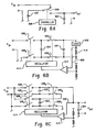
Figures 6A, 6B, 6C ,6D, and 6E depict energy converters. - With reference to
Figure 1 , an intrinsicallysafe flashlight 100 includes a generallycylindrical housing 101 which defines abattery receiving region 108 configured to receive first 110. and second 11O2 batteries such as generally cylindrical D-size cells. As illustrated, the housing includes a generallycylindrical body 102, afirst end cap 104, and asecond end cap 106. Theend caps body 102, for example throughthreads - The
flashlight 100 also includes a light management system such as a generallyparabolic reflector 112 and lens 114, acircuit board 116, and alight source 118 such as one or more light emitting diodes (LEDs) which, as illustrated, are carried by thesecond end cap 106. A user-operable switch 120 such as a pushbutton on/off switch allows a user to control the operation of theflashlight 100 as desired. As illustrated inFigure 1 , theswitch 120 is actuated through aflexible switch cover 122. - The
batteries 110,switch 120 andcircuit board 116 configured as an intrinsically safe electrical circuit suitable for use in hazardous locations and through which energy from thebatteries 110 is used to selectively illuminate thelight source 118. - Turning now to
Figure 2 , the circuit includes activeelectrical circuitry 202 such as a direct current to direct current (DC to DC)converter circuit 202. Theconverter circuit 202, which is configured as a capacitive charge pump, uses charge pump capacitors CCPI, CCP2 to convert the energy provided by thebatteries 110 to a form suitable for powering thelight source 118. Whileconverter circuits 202 which utilize capacitive energy storage elements are especially well suited for intrinsically safe applications, inductive or other energy conversion elements may also be implemented. - As the batteries are ordinarily capable of supplying energy sufficient to render the
flashlight 100 non-intrinsically safe, an energy limiter such as a fuse F1 and a current limiting resistor RL are disposed electrically in series between thebatteries 110 and the input Vin of theconverter circuit 202. The fuse F1 and current limiting resistor RL cooperate to limit the available energy so that any spark or thermal effect produced during normal operation or under fault conditions is incapable of causing ignition of a mixture of a flammable or combustible material in air in the mixture's most easily ignitable concentration. The energy limiter should be located as near as practicable to thebattery receiving region 108, and the requisiteelectrical connections 124 should be suitably spaced and insulated so as prevent or otherwise reduce the likelihood of shorts, opens, or other faults. - The
light source 118 is connected to the output Vout of thecharge pump 202. In one implementation, thelight source 118 is a 1 Watt (W) white LED. Such LEDs typically have a nominal forward voltage of approximately 3.6 VDC (with specification limits typically ranging from roughly 3 to 4 VDC) and an operating current of approximately 350 milliamperes (mA). Where theflashlight 100 is powered by two (2) series connected alkaline primary batteries each having a nominal open circuit output voltage of 1.5 VDC, the nominal open circuit input voltage to the charge pump is about 3 VDC. Two series connected Nickel Metal Hydride (NiNH) secondary batteries having a nominal open circuit output voltage of 1.2VDC likewise provide a nominal voltage 2.4VDC. Note that theconverter circuit 202 is advantageously configured to have an input dynamic range which is suitable for use with either chemistry and which accommodates decreases in input voltage which occur as thebatteries 100 are loaded and/or become discharged. In either case, theconverter 202 ordinarily serves as a voltage step up or boost converter. - A feedback resistor RFB is connected in series with the
light source 118. The resistor RFB provides a feedback signal VFB to theconverter circuit 202, which implements a closed loop control circuit which varies the average output voltage Vout as needed to maintain the LED current ILED at a desired operating current. In this sense, theconverter 202 can be considered to operate as a current source. - One advantage of such an arrangement is that it tends to ameliorate the effects of variations in the performance of the
light source 118, as well as changes in battery output voltage, particularly as thebatteries 110 discharge. Those of ordinary skill in the art will recognize that, while the illumination provided by thelight source 118 is a function of LED current ILED, the converter need not function as an ideal current source. - The circuit also includes decoupling capacitors C1, C3 such as 0.01 µF ceramic capacitors and a filter capacitor C2 such as a 1.0 microfarad (µF) electrolytic capacitor.
- A suitable charge pump for use in the
converter circuit 202 is the BCT3511S DC/DC converter integrated circuit (IC) available from BlueChips Technology of Selangor Darul Ehsa, Malaysia (www.bluechipstech.com). In the case of an intrinsically safe circuit suitable for use in Class I,Division 1, Group A, B, C, and D locations pursuant to the UL913 standard, a suitable fuse F1 is a very fast acting, encapsulated 750 mA fuse such as a Series 263 fuse available from Littlefuse Company of Des Plaines, Illinois USA (www.littlefuse.com). A suitable resistor RL is a 0.25 Ohm (Ω) +/- 5%, 1 Watt (W) resistor. Note also that the thermal characteristics of the various components should be selected so that the temperature rise under fault conditions is insufficient to cause ignition of flammable or combustible materials. Internal wiring and other connections should also be insulated and spaced appropriately. One source of guidance with respect to thermal issues, reactive component values, spacing, and the like is the known UL 913 standard. - Various alternatives are contemplated. The
flashlight 100 may be designed as intrinsically safe for use in other classes, divisions or groups (e.g., classes II or III,Division 2, Groups B-G, or the like). Theflashlight 100 may also be designed to conform to IEC, ATEX/CENELEC, or other classification standards, for example inZones - While the above discussion has focused on a flashlight having two (2) D-size batteries and a light source which includes a single 1 W LED, other battery types and/or
light sources 118 are contemplated. In one variation, theflashlight 100 is configured to accept two (2) AA size batteries and thelight source 118 includes three (3) 72mW LEDs. A suitable circuit implementation is shown inFigure 3 . Note that a ballast resistor RB such as a 4.7Ω resistor is placed in series with each LED, and the value of the feedback resistor RFB is selected so that the total LED current ILED is approximately 175mA. - The flashlight may also be designed to accept AAA-size, C-size, Type N, other generally cylindrical batteries, prismatic batteries, coin cells, or other batteries, either alone or in combination. Other chemistries are also contemplated, including but not limited to lithium ion (Li Ion), lithium iron disulfide (Li/FeS2), and nickel cadmium (NiCd), provided that the batteries are otherwise suitable for use in the desired hazardous location. The
flashlight 100 may also be configured to accept only asingle battery 110 or three (3) ormore batteries 110. - Other numbers and wattages of LEDs may also be provided, as may colors other than white. Examples include cyan, green, amber, red-orange, and red. Two (2) or more of the LEDs may also be connected electrically in series.
- While the above discussion has focused on a
flashlight 100 having a generally cylindrical form factor, other form factors are also contemplated. For example, the flashlight may be configured as a lantern style flashlight or as a wearable light. In one variation, theflashlight 100 includes clip or carabineer for attaching the flashlight to a belt or other article of clothing. In still another variation, theflashlight 100 is configured as a headlamp, for example as part of headgear such as a safety hardhat or connected to a headband which is worn around the user's head. Theflashlight 100 may also include one or more flat surfaces which facilitate placement of the flashlight on suitable surface. It may also include suitable clamps, brackets, cut and loop fasteners, magnets, or other fasteners for selectively attaching theflashlight 100 to an object in the external environment. - The
flashlight 100 may also be configured to produce other than a light beam, for example to provide an area light. It may also include more than one independently controllablelight source 118,batteries 110, and/orcircuits 202. Thus, for example, onelight source 118 may provide a light beam while another serves as an area light. The flashlight may also include alight source 118 which serves as a distress or signal light, for example by flashing and/or emitting a red or other suitably colored light. The intensity of the light provided by alight source 118 may be varied by varying the value of its feedback resistor RFB, for example via a potentiometer, switch, or other user operable brightness control. In one implementation, the intensity is substantially continuously variable. In another, the intensity is variable between three or more levels, for example between an off state and two (2) or more illuminated conditions. Where thelight source 118 includes multiple LEDs, the illumination intensity may also be varies by selectively powering one or more of the LEDs. -
Other converter 202 implementations are also contemplated. For example, theconverter 202 may be implemented using other DC to DC converter ICs, discrete circuitry, or combinations thereof. Note also that the filter capacitor C2 may be omitted, particularly where the switching frequency of theconverter circuit 202 is fast enough so that any resultant flicker in the LED output is not noticeable or otherwise acceptable. - Other converter topologies are also contemplated. Additional circuits are discussed in commonly owned
U.S. Patent Application Serial Number 11/523157 to Spartano et al. - The converter may be configured as a voltage source, a current source, or as having other output characteristics which are suitable for powering the device electrical circuitry. Note that the converter need not function as an ideal voltage or current source. Thus, converter is ordinarily designed to have an equivalent series or parallel resistance (as the case may be) which is compatible with the requirements of the device electrical circuitry.
- In one implementation, and with reference to
Figure 5 , the energy converter includes a charge pump which includes one morecharge pump capacitors 502, one or more semiconductor or other switches 504, and acontroller 506. Where closed loop control of the energy converter output is provided, afeedback signal 508 is provided to thecontroller 506. -
Figure 6A depicts a charge pump which is particularly well suited to situations requiring step down voltage conversion. As illustrated, the charge pump includes a charge I pumpcapacitor 602, an output energy storage device such as acapacitor 604, acontroller 606, and asemiconductor switch 608. Thecontroller 606 varies theswitch 608 between a first state (shown inFigure 6A ) in which thecharge pump capacitor 602 receives energy from the batteries and a second state in which energy from thecharge pump capacitor 602 is transferred to theoutput capacitor 604. Thecontroller 606 may also include a control circuit which adjusts the operation of theswitch 608 based on a measured value of the output voltage or current. Though illustrated as a single pole double throw (SPDT) switch, theswitch 608 may also be implemented using semiconductor or other devices which function as single pole single throw (SPST) switches. - A charge pump which operates as a current source is shown in
Figure 6B . As illustrated, the circuit includes a flyingcharge pump capacitor 602, anoutput capacitor 604, and a plurality ofswitches charge pump capacitor 602 is transferred to the device electrical circuitry side when theswitches Figure 6B ); the flyingcapacitor 602 is charged when theswitches switches current sense resistor 610 connected electrically in series with the deviceelectrical circuitry 650 provides a feedback signal indicative of the device electrical circuitry current Thecontroller 606 includes acontrol circuit 612 and anoscillator 614 which cooperate to control the operation of theswitches 608 to provide the desired current output. - A charge pump which operates as a regulated voltage boost converter is shown in
Figure 6C . As illustrated, the circuit includes first 6021, and 6022 second flying charge pump capacitors, anoutput capacitor 604, and a plurality ofswitches Figure 6C ), thecapacitors 602 are connected electrically in series; when connected to the input side, thecapacitors 602 are connected electrically in parallel. Such a configuration provides up to about a two (2) times voltage boost. Thecontroller 606 includes acontrol circuit 612 and anoscillator 614. As illustrated, thecontroller 612 receives a feedback signal 308 indicative of theconverter 110 output voltage. Thecontrol circuit 612 andoscillator 614 cooperate to control the operation of theswitches 608 to provide the desired output voltage. Note that a voltage divider may also be implemented by connecting the capacitors in series when connected to the input and in parallel when connected to the output. - A charge pump which operates as an inverting boost converter is shown in
Figure 6D . As illustrated, the circuit includes a plurality of flyingcharge pump capacitors 602n, anoutput capacitor 604, a plurality ofswitches 6081-m, and acontroller 606. As configured, the circuit provides up to approximately a negative n-times voltage boost Thecontroller 606 provides the desired output regulation, if any. - A charge pump which provides multiple operating modes is shown in
Figure 6E . As illustrated, the circuit includes first 6021 and second 6022 flying capacitors, anoutput capacitor 604, a plurality ofswitches 6081-9, and acontroller 606. In one mode, the input is connected directly to the output by closingswitches switches Figure 6A so as to provide the desired output. In another mode, thecapacitors 602 are charged in alternating clock phases so that the converter functions as a voltage doubler. In a first clock phase, thefirst capacitor 6021, is connected to the input throughswitches second capacitor 6022 is stacked on top of the input and connected to the output throughswitches second capacitor 6022 is connected to the input throughswitches first capacitor 6021 is stacked on top of the input and connected to the output throughswitches capacitors 602 are connected in series for charging and in parallel for transferring energy to the output. In still another mode, thecapacitors 602 are connected in parallel for charging and in series for transferring energy to the output so that the circuit functions as a voltage tripler. - The desired operating mode may be dynamically selected by the
controller 606 based on thefeedback signal 508. Such an implementation is particularly attractive in situations where the operating characteristics of the device electrical circuitry may change based on ambient conditions or otherwise as a function of time, or where it is desirable to account for changes in the input voltage, for example as the batteries discharge. While described as a circuit having multiple dynamically selectable operating modes, those of ordinary skill in the art will recognize that the circuit may be configured to provide only one or a subset of the described modes. - Note also that the
switch 120 may also be located on the negative side of thebatteries 110. Theswitch 120 may also be implemented as a slide, toggle, rocker, rotary, or other switch. - Operation of the
flashlight 100 will now be described in relation toFigure 4 . At 402, electrical energy is received from a battery or batteries disposed in thebattery receiving region 108 of the flashlight. At 404, theelectrical circuit 202 supplies energy from the battery(ies) to thelight source 118. At 406, theflashlight 100 is operated in a hazardous location. In the event of a fault condition such as a component failure or a short circuit, the fuse F1 and the current limit resistor RL limit the available energy atstep 408. - The invention has been described with reference to the preferred embodiments. Of course, modifications and alterations will occur to others upon reading and understanding the preceding description. It is intended that the invention be construed as including all such modifications and alterations insofar as they come within the scope of the appended claims and the equivalents thereof.
- 1. An intrinsically safe flashlight comprising:
- a battery receiving region (108) which accepts two or fewer generally cylindrical batteries (110);
- at least a first light emitting diode (118);
- a converter circuit (116) which converts electrical energy from the two or fewer batteries to a form suitable for powering the at least a first light emitting diode (118), wherein the flashlight is intrinsically safe for use in a hazardous location.
- 2. The flashlight of 1 wherein the two or fewer batteries (110) are nominal 1.2 or 1.5VDC batteries and the at least a first light emitting diode (118) has a forward voltage between about 3 and 4 VDC.
- 3. The flashlight of 1 or 2 wherein the energy provided to the converter circuit (116) is limited so that the flashlight is intrinsically safe for use in a location where ignitable concentrations of flammable gases, vapors or liquids can exist under normal operating conditions, may frequently exist because of repair or maintenance operations or because of leakage, or may exist because of an equipment breakdown that simultaneously causes the equipment to become a source of ignition.
- 4. The flashlight of any of 1-3 wherein the converter circuit (116) includes a capacitive voltage converter (202).
- 5. The flashlight of any of 1-4 wherein the converter circuit (116) includes a capacitive charge pump (202).
- 6. The flashlight of any of 1-5 wherein the converter circuit (116) receives a signal indicative of a current through the at least a first light emitting diode (118).
- 7. The flashlight of any of 1-6 wherein the flashlight has a generally cylindrical exterior form factor.
- 8. The flashlight of any of 1-7 including a reflector (112) which reflects light produced by the at least a first light emitting diode (118) and the flashlight generates a light beam.
- 9. The flashlight of any of 1-7 wherein the flashlight provides an area light.
- 10. The flashlight of any of 1-9 wherein the battery receiving region (108) accepts 2 D-size batteries.
- 11. The flashlight of 1 wherein the battery receiving region (108) accepts 2 AA-size batteries and the flashlight includes a plurality of light emitting diodes (118).
- 12. The flashlight of any of 1-11 including user-operable means (120, RFB) for varying an intensity of the light produced by the at least one light emitting diode (118) to at least a first non-illuminated level, a first illuminated level, and a second illuminated level.
- 13. An intrinsically safe, battery powered flashlight including a first light source (118), a battery receiving region (108), and an intrinsically safe, active electrical circuit (116) which uses energy from the at least a first battery (110) received in the battery receiving region (108) to power the light source (118).
- 14. The flashlight of 13 wherein the light source (118) includes a light emitting diode and the battery receiving region (108) receives a battery (110) having a nominal voltage of about 1.2 to 1.5 VDC.
- 15. The flashlight of 13 wherein the circuit (116) limits the energy from the at least a first battery (110) so that, in the event of a flashlight fault condition, the flashlight is intrinsically safe for use in a hazardous location.
- 16. The flashlight of 15 wherein the hazardous location is a location where ignitable concentrations of flammable gases, vapors, or liquids are present for long periods of time or continuously.
- 17. The flashlight of 13 wherein the converter circuit (116) includes a charge pump step up converter (202).
- 18. The flashlight of . 13 wherein the converter circuit (116) functions as a current source.
- 19. The flashlight of 18 wherein the current supplied by the current source is user adjustable to at least first, second, and third values.
- 20. The flashlight of 13 wherein the flashlight includes a second light source (1182), and wherein the first and second light sources are independently user-operable.
- 21. The flashlight of 13 wherein the flashlight is configured as a headlamp.
- 22. The flashlight of 21 wherein the flashlight includes a headband.
- 23. The flashlight of 113 wherein the flashlight provides an area light.
- 24. The flashlight of 13 including fastening means for selectively attaching the flashlight at a fixed location in the external environment.
- 25. The flashlight of 13 wherein the light source (118) includes a single LED.
- 26. The flashlight of 13 wherein the active electrical circuit includes a passive electrical component.
- 27. The flashlight of 26 wherein the passive electrical component includes a capacitor.
- 28. A method comprising:
- receiving electrical energy from a battery (110) disposed in a battery receiving region (108) of a flashlight;
- using an intrinsically safe active electrical circuit (116) to supply electrical energy received from the battery (110) to a first light source (118) of the flashlight.
- 29. The method of 28 wherein the flashlight is intrinsically safe for use in a Group I, Division I hazardous location.
- 30. The method of 28 wherein the flashlight is intrinsically safe for use in a Zone 0 hazardous location.
- 31. The method of 28 wherein the light source (118) includes a first white light emitting diode.
- 32. The method of 28 wherein the light source (118) includes second and third light emitting diodes.
- 33. The method of 28 wherein receiving includes receiving electrical energy from a AAA, AA, C, or D-size battery.
- 34. The method of 28 wherein receiving includes receiving electrical energy from two or fewer batteries (110).
- 35. The method of 28 wherein receiving includes receiving electrical energy from four or more batteries (110).
- 36. The method of 28 including using the first light source (118) to generate a light beam.
- 37. The method of 28 including attaching the flashlight to an article of clothing.
- 38. The method of 28 including
using the first light source (1181) to illuminate an object;
using a second light source (1182) of the flashlight to signal a distress condition. - 39. The method of 28 including wearing the flashlight on the head of a human user.
- 40. The method of 28 wherein the flashlight is a human-portable flashlight and the method includes carrying the flashlight to a desired location, stationarily attaching the flashlight to an object at the desired location, and detaching the flashlight from the object.
- 41. The method of 28 including
measuring, during an operation of the flashlight, an electrical current supplied to the light source (118);
using the measured value of the current to adjust the current supplied to the light source (118). - 42. A human-portable lighting apparatus comprising:
- a battery receiving region (108) adapted to receive at least a first battery (110);
- a user operable control (120);
- a light emitting diode light source (118);
- an intrinsically safe charge pump (202) which is operatively connected to the user control (120) and which uses energy from the at least a first battery (110) to selectively power the light source (118).
- 43. The apparatus of 1 including a lantern-style flashlight housing.
Claims (15)
- An intrinsically safe flashlight comprising:- a battery receiving region (108) which accepts two or fewer generally cylindrical batteries (110);- at least a first light emitting diode (118); and- a converter circuit (116), wherein the converter circuit (116) includes a charge pump (202), which converts electrical energy from the two or fewer batteries to a form suitable for powering the at least a first light emitting diode (118).
- The flashlight of claim 1 wherein the two or fewer batteries (110) are nominal 1.2 or 1.5 VDC batteries and the at least a first light emitting diode (118) has a forward voltage between about 3 and 4 VDC.
- The flashlight of claim 1 or 2 wherein the energy provided to the converter circuit (116) is limited so that the flashlight is intrinsically safe for use in a location where ignitable concentrations of flammable gases, vapors or liquids exist under normal operating conditions.
- The flashlight of any of claims 1 to 3 wherein the converter circuit (116) includes a capacitive voltage converter (202).
- The flashlight of any of claims 1 to 4 , wherein the flashlight is intrinsically safe for use in a hazardous location and the charge pump (202) is a capacitive charge pump (202).
- The flashlight of any of claims 1 to 5 wherein the converter circuit (116) receives a signal indicative of a current through the at least as first light emitting diode (118) and the converter circuit (116) varies an average output voltage to maintain the current of the first light emitting diode (118) at a desired operating current.
- The flashlight of any of claims 1 to 6 wherein the flashlight has a generally cylindrical exterior form factor.
- The flashlight of any of claims 1 to 7 including a reflector (112) which reflects light produced by the at least a first light emitting diode (118) and the flashlight generates a light beam.
- The flashlight of any of claims 1 to 7 wherein the flashlight provides an area light.
- The flashlight of claim 1 wherein the battery receiving region (108) accepts 2 AA-size batteries and the flashlight includes a plurality of light emitting diodes (118).
- The flashlight of any of claims 1 to 10 including user-operable means (120, RFB) for varying an intensity of the light produced by the at least one light emitting diode (118) to at least a first non-illuminated level, a first illuminated level, and a second illuminated level.
- An intrinsically safe, battery powered flashlight including a first light source (118), a battery receiving region (108), and an intrinsically safe, active electrical circuit (116) including a charge pump (202), wherein the circuit uses energy from at least a first battery (110) received in the battery receiving region (108) to power the light source (118).
- The flashlight of claim 12 wherein the light source (118) includes a light emitting diode and the battery receiving region (108) receives a battery (110) having a nominal voltage of about 1.2 to 1.5 VDC.
- The flashlight of claim 12 wherein the circuit (116) limits the energy from the at least a first battery (110) so that, in the event of a flashlight fault condition, the flashlight is intrinsically safe for use in a hazardous location.
- The flashlight of claim 12 wherein the flashlight is configured as a headlamp.
Applications Claiming Priority (2)
| Application Number | Priority Date | Filing Date | Title |
|---|---|---|---|
| US11/523,149 US7651239B2 (en) | 2006-09-19 | 2006-09-19 | Intrinsically safe flashlight |
| EP07838385A EP2069681A1 (en) | 2006-09-19 | 2007-09-18 | Intrinsically safe flashlight |
Related Parent Applications (1)
| Application Number | Title | Priority Date | Filing Date |
|---|---|---|---|
| EP07838385.8 Division | 2007-09-18 |
Publications (2)
| Publication Number | Publication Date |
|---|---|
| EP2405180A2 true EP2405180A2 (en) | 2012-01-11 |
| EP2405180A3 EP2405180A3 (en) | 2013-11-20 |
Family
ID=38894043
Family Applications (2)
| Application Number | Title | Priority Date | Filing Date |
|---|---|---|---|
| EP11183839.7A Withdrawn EP2405180A3 (en) | 2006-09-19 | 2007-09-18 | Intrinsically safe flashlight |
| EP07838385A Withdrawn EP2069681A1 (en) | 2006-09-19 | 2007-09-18 | Intrinsically safe flashlight |
Family Applications After (1)
| Application Number | Title | Priority Date | Filing Date |
|---|---|---|---|
| EP07838385A Withdrawn EP2069681A1 (en) | 2006-09-19 | 2007-09-18 | Intrinsically safe flashlight |
Country Status (5)
| Country | Link |
|---|---|
| US (2) | US7651239B2 (en) |
| EP (2) | EP2405180A3 (en) |
| CN (1) | CN101517307B (en) |
| AU (1) | AU2007297732A1 (en) |
| WO (1) | WO2008036250A1 (en) |
Cited By (1)
| Publication number | Priority date | Publication date | Assignee | Title |
|---|---|---|---|---|
| CN110769551A (en) * | 2019-10-23 | 2020-02-07 | 连云港杰瑞自动化有限公司 | Active light source control circuit for explosion-proof occasion |
Families Citing this family (29)
| Publication number | Priority date | Publication date | Assignee | Title |
|---|---|---|---|---|
| AUPR574901A0 (en) | 2001-06-18 | 2001-07-12 | Eveready Battery Company Inc. | An outdoor lighting device |
| US20150354792A1 (en) * | 2009-11-19 | 2015-12-10 | Tseng-Lu Chien | Interchange Universal Kits for LED Light Device |
| US7550943B2 (en) * | 2006-09-19 | 2009-06-23 | Eveready Battery Company, Inc. | Intrinsically safe battery-powered device |
| US7651239B2 (en) * | 2006-09-19 | 2010-01-26 | Eveready Battery Co., Inc. | Intrinsically safe flashlight |
| US7909478B2 (en) * | 2007-08-06 | 2011-03-22 | Fiskars Brands, Inc. | Multi battery type flashlight |
| US20090135607A1 (en) * | 2007-11-27 | 2009-05-28 | Cooper Technologies Company | Lighting fixture and method |
| CN101858580B (en) * | 2010-04-29 | 2012-10-03 | 海洋王照明科技股份有限公司 | Flashlight and conductive column thereof |
| US20120085631A1 (en) * | 2010-10-07 | 2012-04-12 | Ching-Hsiang Wang | Waterproof Structure for Press Switch of Flashlight |
| US8727561B2 (en) | 2011-03-17 | 2014-05-20 | Streamlight, Inc. | Light and/or device having a compartment accommodating batteries of different types, sizes and/or shapes |
| US8807781B2 (en) | 2011-05-05 | 2014-08-19 | Streamlight, Inc. | Portable light with safety lock |
| CN202253393U (en) * | 2011-07-25 | 2012-05-30 | 阳西星际科技有限公司 | Improved optical stack and electric torch employing same |
| CN103178606B (en) * | 2011-12-26 | 2014-11-26 | 中国科学院沈阳自动化研究所 | Standby power for down-hole emergency refuge facility |
| US10060582B2 (en) * | 2012-01-24 | 2018-08-28 | Tactical Impulse Llc | Modular flashlight system with retention device |
| US9285105B2 (en) | 2012-05-08 | 2016-03-15 | Streamlight, Inc. | Head light having a rotatable face cap with plural lenses |
| US9275818B1 (en) * | 2013-05-20 | 2016-03-01 | Mark A. Zeh | Method of making and use of an automatic system to increase the operating life of vacuum tubes with a vacuum tube device |
| WO2015168351A1 (en) | 2014-05-02 | 2015-11-05 | Swagelok Company | Fluid sample system and method |
| HK1198615A2 (en) | 2014-11-19 | 2015-04-30 | Man Yin Lam | Lighting and diffuser apparatus for a flashlight |
| CN110069007B (en) * | 2015-03-06 | 2022-12-09 | 普雷斯弗雷克斯股份公司 | Miniature user-powered lighting device, system and method of use thereof |
| US9713217B2 (en) | 2015-03-25 | 2017-07-18 | Bayco Products, Inc. | Duty cycle brightness control for lighting device |
| DE102015223362A1 (en) | 2015-11-25 | 2017-06-01 | Minimax Gmbh & Co. Kg | Explosion-proof housing for means for transmitting and receiving electromagnetic radiation |
| CN107366843B (en) * | 2016-12-20 | 2021-04-09 | 深圳市海洋王照明工程有限公司 | Explosion-proof portable lamp |
| US10071673B2 (en) | 2017-02-13 | 2018-09-11 | Omix-Ada, Inc. | Modular light and accessory bar for vehicles |
| USD939139S1 (en) | 2019-04-09 | 2021-12-21 | Waters Industries, Inc. | Compact flashlight |
| US10775001B1 (en) | 2019-04-09 | 2020-09-15 | Waters Industries, Inc. | Compact flashlight |
| CN111836433A (en) * | 2019-04-22 | 2020-10-27 | 厦门赢科光电有限公司 | A control circuit for a power supply |
| USD951505S1 (en) | 2019-05-02 | 2022-05-10 | Milwaukee Electric Tool Corporation | Headlamp |
| WO2021022145A1 (en) | 2019-08-01 | 2021-02-04 | Sirius Signal, LLC | Visual distress signal device |
| GB2602335B (en) * | 2020-12-23 | 2024-08-14 | The Wolf Safety Lamp Company Ltd | Torch for use in explosive atmospheres |
| USD1072303S1 (en) | 2021-11-22 | 2025-04-22 | Milwaukee Electric Tool Corporation | Headlamp |
Family Cites Families (33)
| Publication number | Priority date | Publication date | Assignee | Title |
|---|---|---|---|---|
| US3711768A (en) * | 1971-04-05 | 1973-01-16 | B Frazin | Combined electric continuity checker and flashlight |
| US3973139A (en) * | 1973-05-23 | 1976-08-03 | Rca Corporation | Low power counting circuits |
| US4164145A (en) | 1978-03-20 | 1979-08-14 | De Laval Turbine Inc. | Self-powered electrical meter for display of a liquid-level or the like measurement |
| US4346329A (en) * | 1979-08-27 | 1982-08-24 | Schmidt Robert C H | Aiming post light |
| SU1154461A1 (en) | 1983-12-08 | 1985-05-07 | Ордена Октябрьской Революции И Ордена Трудового Красного Знамени Институт Горного Дела Им.А.А.Скочинского | Visual monitoring device for mines |
| GB2222449B (en) | 1988-09-06 | 1992-01-02 | Top Line Leisure Ltd | Improvements in or relating to search lamps and torches |
| US5130726A (en) | 1989-02-28 | 1992-07-14 | Canon Kabushiki Kaisha | Ink jet recording apparatus |
| US5149190A (en) * | 1989-05-24 | 1992-09-22 | Bay Industrial And Mine Tech Inc. | Portable safety device |
| US5563456A (en) * | 1992-02-06 | 1996-10-08 | Murphy Management Inc. | Solar powered annunciator |
| US5438225A (en) * | 1992-02-06 | 1995-08-01 | Murphy Management Inc. | Solar powered annuciator |
| GB9211479D0 (en) | 1992-05-30 | 1992-07-15 | Topline Leisure Ltd | Improvements in or relating to search lamps and torches |
| US5262728A (en) * | 1992-08-25 | 1993-11-16 | Shershen Eugene D | Combination flashlight/lantern electric continuity tester |
| US5386592A (en) * | 1993-09-07 | 1995-02-07 | Checkeroski; Mark | Headband and flashlight holding construction |
| US5685632A (en) | 1995-05-31 | 1997-11-11 | Rayovac Corporation | Electrically conductive plastic light source |
| US6095661A (en) | 1998-03-19 | 2000-08-01 | Ppt Vision, Inc. | Method and apparatus for an L.E.D. flashlight |
| US6857758B1 (en) | 2000-02-25 | 2005-02-22 | Streamilght, Incorporated | Solid state light source, as for a flashlight |
| US6556067B2 (en) * | 2000-06-13 | 2003-04-29 | Linfinity Microelectronics | Charge pump regulator with load current control |
| US6857756B2 (en) | 2001-04-11 | 2005-02-22 | General Manufacturing, Inc. | LED work light |
| US7682036B2 (en) * | 2001-04-11 | 2010-03-23 | General Manufacturing, Inc. | Intrinsically safe light |
| CN2515509Y (en) | 2002-01-15 | 2002-10-09 | 杨炳和 | Explosion-proof safety miner's lamp |
| US6853566B2 (en) * | 2002-04-18 | 2005-02-08 | Ricoh Company, Ltd. | Charge pump circuit and power supply circuit |
| US6727805B2 (en) | 2002-05-14 | 2004-04-27 | Fire Factory, Llc | Signaling retention device |
| AT6505U1 (en) | 2002-09-16 | 2003-11-25 | Peter Moser | FLASHLIGHT WITH AT LEAST ONE LED AS A LAMP |
| US6987366B2 (en) * | 2002-12-31 | 2006-01-17 | Sun Yu | Step down circuit for an LED flashlight |
| US6798348B1 (en) | 2003-04-03 | 2004-09-28 | Scott Wilker | Ergonomically designed tool handle |
| US6859145B2 (en) | 2003-04-03 | 2005-02-22 | Scott Wilker | Safety system |
| JP3759134B2 (en) * | 2003-08-29 | 2006-03-22 | ローム株式会社 | Power supply |
| CN2723811Y (en) | 2004-07-19 | 2005-09-07 | 胡宪亮 | Wood safety portable lamp |
| US7241025B2 (en) * | 2005-01-24 | 2007-07-10 | Surefire, Llc | Switch actuated flashlight with current limiter |
| EP2045508A1 (en) * | 2005-10-07 | 2009-04-08 | Black & Decker, Inc. | Flashlight |
| US7651240B2 (en) * | 2006-01-10 | 2010-01-26 | Bayco Products. Ltd. | Combination task lamp and flash light |
| US7651239B2 (en) * | 2006-09-19 | 2010-01-26 | Eveready Battery Co., Inc. | Intrinsically safe flashlight |
| US7550943B2 (en) * | 2006-09-19 | 2009-06-23 | Eveready Battery Company, Inc. | Intrinsically safe battery-powered device |
-
2006
- 2006-09-19 US US11/523,149 patent/US7651239B2/en not_active Expired - Fee Related
-
2007
- 2007-09-18 EP EP11183839.7A patent/EP2405180A3/en not_active Withdrawn
- 2007-09-18 WO PCT/US2007/020168 patent/WO2008036250A1/en not_active Ceased
- 2007-09-18 EP EP07838385A patent/EP2069681A1/en not_active Withdrawn
- 2007-09-18 CN CN2007800348770A patent/CN101517307B/en not_active Expired - Fee Related
- 2007-09-18 AU AU2007297732A patent/AU2007297732A1/en not_active Abandoned
-
2009
- 2009-12-03 US US12/629,967 patent/US7950820B2/en not_active Expired - Fee Related
Cited By (1)
| Publication number | Priority date | Publication date | Assignee | Title |
|---|---|---|---|---|
| CN110769551A (en) * | 2019-10-23 | 2020-02-07 | 连云港杰瑞自动化有限公司 | Active light source control circuit for explosion-proof occasion |
Also Published As
| Publication number | Publication date |
|---|---|
| US20100084981A1 (en) | 2010-04-08 |
| WO2008036250B1 (en) | 2008-05-08 |
| US7950820B2 (en) | 2011-05-31 |
| CN101517307B (en) | 2013-08-14 |
| EP2405180A3 (en) | 2013-11-20 |
| WO2008036250A1 (en) | 2008-03-27 |
| EP2069681A1 (en) | 2009-06-17 |
| US7651239B2 (en) | 2010-01-26 |
| US20080068832A1 (en) | 2008-03-20 |
| CN101517307A (en) | 2009-08-26 |
| AU2007297732A1 (en) | 2008-03-27 |
Similar Documents
| Publication | Publication Date | Title |
|---|---|---|
| EP2405180A2 (en) | Intrinsically safe flashlight | |
| US7952321B2 (en) | Device having an energy converter and an energy limiter to limit supplied electrical energy | |
| US8480249B2 (en) | Method and apparatus for providing an LED light for use in hazardous locations | |
| US20100039049A1 (en) | Positive Temperature Coefficient Light Emitting Diode Light | |
| US8018161B2 (en) | Light unit with internal back-up power supply, communications and display | |
| EP2072887A2 (en) | Light emitting diode cap lamp | |
| US9200794B2 (en) | Fan cooled LED light and housing | |
| MY141642A (en) | Circuitry for portable lighting devices and portable rechargeable electronic devices | |
| EA016489B1 (en) | PORTABLE LIGHTING DEVICE AND POCKET ELECTRIC LANTERN WITH A VISIBLE FLASH FUNCTION | |
| US7215084B1 (en) | Power control arrangement, as for a flashlight | |
| WO1998020276A1 (en) | A portable lighting product, a portable lighting product circuit and a functioning method for a portable lighting product circuit | |
| HK1166120A (en) | Intrinsically safe flashlight | |
| JP5597264B2 (en) | Light emitting diode lighting circuit, LED light source and lamp | |
| US12184108B1 (en) | Energy storage power supply | |
| FI97935C (en) | Lighting systems | |
| AU2014292490B2 (en) | Lighting device | |
| CN223693254U (en) | A type of energy storage power supply | |
| KR100715430B1 (en) | Emergency light using light emitting diode | |
| UA45690A (en) | BATTERY LAMP | |
| CZ8800U1 (en) | Compact light source | |
| AU2017279725A1 (en) | Lighting Apparatus | |
| UA54070A (en) | Lighting device | |
| KR20010010800A (en) | Sleeping lamp | |
| TW200742490A (en) | Improved circuitry for portable lighting devices and portable rechargeable electronic devices |
Legal Events
| Date | Code | Title | Description |
|---|---|---|---|
| AC | Divisional application: reference to earlier application |
Ref document number: 2069681 Country of ref document: EP Kind code of ref document: P |
|
| AK | Designated contracting states |
Kind code of ref document: A2 Designated state(s): AT BE BG CH CY CZ DE DK EE ES FI FR GB GR HU IE IS IT LI LT LU LV MC MT NL PL PT RO SE SI SK TR |
|
| PUAI | Public reference made under article 153(3) epc to a published international application that has entered the european phase |
Free format text: ORIGINAL CODE: 0009012 |
|
| REG | Reference to a national code |
Ref country code: HK Ref legal event code: DE Ref document number: 1166120 Country of ref document: HK |
|
| PUAL | Search report despatched |
Free format text: ORIGINAL CODE: 0009013 |
|
| AK | Designated contracting states |
Kind code of ref document: A3 Designated state(s): AT BE BG CH CY CZ DE DK EE ES FI FR GB GR HU IE IS IT LI LT LU LV MC MT NL PL PT RO SE SI SK TR |
|
| RIC1 | Information provided on ipc code assigned before grant |
Ipc: F21V 25/04 20060101ALI20131017BHEP Ipc: F21V 21/08 20060101ALI20131017BHEP Ipc: F21Y 101/02 20060101ALN20131017BHEP Ipc: F21L 4/02 20060101ALI20131017BHEP Ipc: H05B 33/08 20060101ALN20131017BHEP Ipc: F21L 4/00 20060101AFI20131017BHEP Ipc: F21V 25/12 20060101ALI20131017BHEP |
|
| 17P | Request for examination filed |
Effective date: 20140319 |
|
| RBV | Designated contracting states (corrected) |
Designated state(s): AT BE BG CH CY CZ DE DK EE ES FI FR GB GR HU IE IS IT LI LT LU LV MC MT NL PL PT RO SE SI SK TR |
|
| RAP1 | Party data changed (applicant data changed or rights of an application transferred) |
Owner name: ENERGIZER BRANDS, LLC |
|
| STAA | Information on the status of an ep patent application or granted ep patent |
Free format text: STATUS: THE APPLICATION IS DEEMED TO BE WITHDRAWN |
|
| 18D | Application deemed to be withdrawn |
Effective date: 20160401 |