EP2405158A1 - Friction gearing - Google Patents
Friction gearing Download PDFInfo
- Publication number
- EP2405158A1 EP2405158A1 EP10750661A EP10750661A EP2405158A1 EP 2405158 A1 EP2405158 A1 EP 2405158A1 EP 10750661 A EP10750661 A EP 10750661A EP 10750661 A EP10750661 A EP 10750661A EP 2405158 A1 EP2405158 A1 EP 2405158A1
- Authority
- EP
- European Patent Office
- Prior art keywords
- roller
- housing
- support plate
- bearing support
- rotation axis
- Prior art date
- Legal status (The legal status is an assumption and is not a legal conclusion. Google has not performed a legal analysis and makes no representation as to the accuracy of the status listed.)
- Granted
Links
Images






Classifications
-
- F—MECHANICAL ENGINEERING; LIGHTING; HEATING; WEAPONS; BLASTING
- F16—ENGINEERING ELEMENTS AND UNITS; GENERAL MEASURES FOR PRODUCING AND MAINTAINING EFFECTIVE FUNCTIONING OF MACHINES OR INSTALLATIONS; THERMAL INSULATION IN GENERAL
- F16H—GEARING
- F16H13/00—Gearing for conveying rotary motion with constant gear ratio by friction between rotary members
- F16H13/02—Gearing for conveying rotary motion with constant gear ratio by friction between rotary members without members having orbital motion
-
- B—PERFORMING OPERATIONS; TRANSPORTING
- B60—VEHICLES IN GENERAL
- B60K—ARRANGEMENT OR MOUNTING OF PROPULSION UNITS OR OF TRANSMISSIONS IN VEHICLES; ARRANGEMENT OR MOUNTING OF PLURAL DIVERSE PRIME-MOVERS IN VEHICLES; AUXILIARY DRIVES FOR VEHICLES; INSTRUMENTATION OR DASHBOARDS FOR VEHICLES; ARRANGEMENTS IN CONNECTION WITH COOLING, AIR INTAKE, GAS EXHAUST OR FUEL SUPPLY OF PROPULSION UNITS IN VEHICLES
- B60K17/00—Arrangement or mounting of transmissions in vehicles
- B60K17/34—Arrangement or mounting of transmissions in vehicles for driving both front and rear wheels, e.g. four wheel drive vehicles
- B60K17/348—Arrangement or mounting of transmissions in vehicles for driving both front and rear wheels, e.g. four wheel drive vehicles having differential means for driving one set of wheels, e.g. the front, at one speed and the other set, e.g. the rear, at a different speed
-
- F—MECHANICAL ENGINEERING; LIGHTING; HEATING; WEAPONS; BLASTING
- F16—ENGINEERING ELEMENTS AND UNITS; GENERAL MEASURES FOR PRODUCING AND MAINTAINING EFFECTIVE FUNCTIONING OF MACHINES OR INSTALLATIONS; THERMAL INSULATION IN GENERAL
- F16H—GEARING
- F16H13/00—Gearing for conveying rotary motion with constant gear ratio by friction between rotary members
- F16H13/10—Means for influencing the pressure between the members
Definitions
- the present invention relates to a proposal of improvement of a friction gearing useful as a driving force distribution device, such as a transfer for a four wheel drive vehicle.
- a patent document 1 discloses a commonly known driving force distribution device. This driving force distribution device is configured to transmit torque through indirect radial pressing contact between a first roller and a second roller with a torque capacity varying according to a state of the inter-roller radial pressing contact.
- Patent document 1 proposes an idea that both of the rollers are supported by a common support plate, and housed in a housing, wherein the support plate bears a reaction force caused by the inter-roller radial pressing contact, and the housing is prevented from being reached by the reaction force.
- Patent document 1 JP 2002-349653 A
- the following considers a situation in which the second roller is made to approach the first roller radially so as to increase the inter-roller radial pressing force (transmitted torque capacity).
- the rotation axis of the second roller approaches the rotation axis of the first roller, and thereby increases an offset from a center of a torque transmitting shaft that transmits torque between the second roller and itself.
- the increase in the offset causes an increase in a relative radial displacement to be absorbed by a universal coupling between the second roller and the torque transmitting shaft, and thereby serves to adversely affect the durability of a driveline including the universal coupling.
- the reaction force increases so as to increase an amount of extension of the common rotation support plate due to a stretching force acting on the first roller and the second roller away from each other.
- the increase in the amount of extension of the rotation support plate serves to reduce the offset between the rotation axis of the second roller and the center of the torque transmitting shaft in the situation where the inter-roller transmitted torque capacity is increased. By nature, this serves to reduce the offset (relative radial displacement) that is to be absorbed by the universal coupling between the second roller and the torque transmitting shaft, and thereby enhance the durability of the driveline including the second roller and the torque transmitting shaft.
- the stretching force acting on the first roller and the second roller away from each other serves to extend the rotation support plate toward the first roller side on one hand, and extend the rotation support plate toward the second roller side on the other hand, so that the amount of extension of the rotation support plate is divided between the first roller side and the second roller side.
- a friction gearing comprises: a housing; and a unit housed in the housing, wherein the unit includes a first roller, a second roller and a rotation support plate; wherein: the first and second rollers are configured to perform frictional transmission in radial pressing contact with each other, and vary a state of the radial pressing contact between the first and second rollers by radial displacement of the second roller with respect to the first roller; the rotation support plate is configured to support the first and second rollers, and receive a reaction force caused by the radial pressing contact between the first and second rollers; and the unit is supported in the housing in a manner that the first roller is rotatably supported with respect to the housing with a rotation axis of the first roller restrained radially.
- a friction gearing according to embodiments of the present invention described below in which a unit which includes a first roller, a second roller and a rotation support plate is supported in a housing in a manner that the first roller is rotatably supported with respect to the housing with a rotation axis of the first roller restrained radially, can concentrate an amount of extension of the rotation support plate to extension toward a second roller side without dividing same between a first roller side and the second roller side, wherein the amount of extension of the rotation support plate is caused by a stretching force acting on the first roller and the second roller away from each other due to radial pressing contact between the first roller and the second roller, and the entire amount of extension of the rotation support plate becomes an amount of extension of the rotation support plate toward the second roller side.
- the second roller when the second roller is made to approach the first roller to increase the inter-roller radial pressing force, it is possible to sufficiently reduce an increase in an offset between a rotation axis of the second roller and a torque transmitting shaft associated with the second roller by the amount of extension of the rotation support plate concentrated to extension toward the second roller side, and thereby reduce the offset (relative radial displacement) that is to be absorbed by a universal coupling between the second roller and the torque transmitting shaft, and thereby enhance the durability of a driveline including the second roller and the torque transmitting shaft.
- FIGS. 1 to 4 show the first embodiment of the present invention.
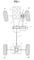
- FIG. 1 is a schematic plan view from above a four wheel drive vehicle, showing a powertrain of the four wheel drive vehicle which is provided with a friction gearing according to the first embodiment of the present invention, wherein the friction gearing is constructed as a driving force distribution device 1.
- the four wheel drive vehicle of FIG. 1 is based on a rear wheel drive vehicle in which rotation from an engine 2 is shifted by a transmission 3, and then transmitted through a rear propeller shaft 4 and a rear final drive unit 5 to left and right rear wheels 6L, 6R, and constructed so that a part of torque to left and right rear wheels (main driving wheels) 6L, 6R is transmitted by driving force distribution device 1 through a front propeller shaft 7 and a front final drive unit 8 to left and right front wheels (auxiliary driving wheels) 9L, 9R, thus achieving four wheel driving.
- Driving force distribution device 1 is thus configured to set torque distribution between left and right rear wheels (main driving wheels) 6L, 6R, and left and right front wheels (auxiliary driving wheels) 9L, 9R by splitting and outputting to left and right front wheels (auxiliary driving wheels) 9L, 9R a part of torque to left and right rear wheels (main driving wheels) 6L, 6R.
- driving force distribution device 1 is constructed as shown in FIG. 2 .
- an input shaft 12 and an output shaft 13 are arranged to laterally cross in a housing 11, which are parallel to one another.
- Input shaft 12 is rotatably supported with respect to housing 11 by ball bearings 14, 15 for free rotation of input shaft 12 about an axis O1.
- Input shaft 12 is rotatably supported also with respect to bearing supports 23, 25 by roller bearings 18, 19. Accordingly, each bearing support 23, 25 is formed with an opening 23a, 25a to which roller bearing 18, 19 is fitted, as shown in FIGS. 3A and 3B .
- Each bearing support 23, 25 is a common rotation support plate supporting both of input shaft 12 and output shaft 13.
- Each bearing support 23, 25 is arranged in housing 11 in a manner that bearing support 23, 25 is in contact with a corresponding inner surface 11b, 11c of housing 11 as shown in FIG. 2 , but is not fixed to inner surface 11b, 11c.
- Both ends of input shaft 12 are made to extend out of housing 11, sealed liquid-tightly by seal rings 27, 28.
- the left end (in FIG. 2 ) of input shaft 12 is coupled to an output shaft of transmission 3 (see FIG. 1 ), and the right end (in FIG. 2 ) of input shaft 12 is coupled through rear propeller shaft 4 (see FIG. 1 ) to rear final drive unit 5.
- Input shaft 12 is formed integrally with a first roller 31 substantially at the center of input shaft 12 in the axial direction of input shaft 12, wherein first roller 31 is coaxially arranged with input shaft 12.
- Output shaft 13 is formed integrally with a second roller 32 substantially at the center of output shaft 13 in the axial direction of output shaft 13, wherein second roller 32 is coaxially arranged with output shaft 13.
- First roller 31 and second roller 32 are arranged in a common plane perpendicular to the axes of input shaft 12 and output shaft 13.
- Output shaft 13 is rotatably supported with respect to housing 11 in an indirect manner with the following configuration. Namely, hollow crankshafts 51L, 51R are located at respective axial ends of second roller 32 that is formed integrally with output shaft 13 substantially at the center of output shaft 13 in the axial direction of output shaft 13, and crankshafts 51L, 51R are clearance-fitted to respective end portions of output shaft 13. Both ends of output shaft 13 are fitted in central holes 51La, 51Ra (whose semidiameter is represented by Ri in the drawings) of crankshafts 51L, 51R.
- Bearings 52L, 52R are disposed in clearance-fitting portions between central holes 51La, 51Ra of crankshafts 51L, 51R and the end portions of output shaft 13, so that output shaft 13 is supported in the central holes 51La, 51Ra of crankshafts 51L, 51R for free rotation about a central axis O2 of central holes 51La, 51Ra.
- crankshafts 51L, 51R are formed with peripheries 51Lb, 51Rb (whose semidiameter is represented by Ro in the drawings) that are eccentric with respect to central holes 51La, 51Ra (central axis O2), so that the central axis O3 of eccentric peripheries 51Lb, 51Rb is eccentric with respect to the axis O2 of central holes 51La, 51Ra (the rotation axis of second roller 32) by eccentricity ⁇ .
- Eccentric peripheries 51Lb, 51Rb of crankshafts 51L, 51R are rotatably supported in the respective bearing supports 23, 25 through bearings 53L, 53R. Accordingly, each bearing support 23, 25 is formed with an opening 23b, 25b to which bearing 53L, 53R is fitted, as shown in FIGS. 3A and 3B .
- Each bearing support 23, 25 is a common rotation support plate supporting both of input shaft 12 and output shaft 13 as described above, and also serves as a common rotation support plate for supporting both of first roller 31 and second roller 32 because first roller 31 and second roller 32 are formed integrally with input shaft 12 and output shaft 13, respectively.
- Each bearing support 23, 25 is configured to have such a size that bearing support 23, 25 is out of contact with an inner wall 11a of housing 11 wherein input shaft 12 is arranged between inner wall 11a and output shaft 13 as shown in FIGS. 2 and 3 , and is out of contact with an inner wall 11d of housing 11 wherein output shaft 13 is arranged between inner wall 11d and input shaft 12 as shown in FIG. 3 .
- each bearing support 23, 25 is provided with a projection 23c, 25c and a projection 23d, 25d which serves to prevent bearing support 23, 25 from swinging about axis O1 of input shaft 12 (first roller 31).
- Each of projection 23c, 25c and projection 23d, 25d is arranged in contact with a bottom surface of a guide groove 11g, 11h formed in the corresponding inner surface 11e, 11f of the housing.
- Each guide groove 11g, 11h is formed to have a narrow shape extending in a tangential line of opening 23b, 25b, and thereby allow projection 23c, 25c to be displaced in the same direction.
- Crankshafts 51L, 51R which are rotatably supported by bearing supports 23, 25 as described above, and second roller 32, are positioned in the axial direction by thrust bearings 54L, 54R, respectively, as shown in FIG. 2 .
- crankshafts 51L, 51R that are closer to and face one another are formed integrally with ring gears 51Lc, 51Rc that have identical specifications and are arranged coaxially with eccentric peripheries 51Lb, 51Rb.
- Ring gears 51Lc, 51Rc are meshed with a common crankshaft driving pinion 55, under condition that crankshafts 51L, 51R are in rotational positions such that the eccentric peripheries 51Lb, 51Rb are aligned with one another in the circumferential direction.
- Crankshaft driving pinion 55 is coupled to a pinion shaft 56. Both ends of pinion shaft 56 are rotatably supported with respect to housing 11 by bearings 56a, 56b. The right end of pinion shaft 56 on the right side of FIG. 2 is exposed outside of housing 11. The exposed end surface of pinion shaft 56 is drivingly coupled, for example, by serration coupling, to an output shaft 45a of an inter-roller pressing force control motor 45 that is attached to housing 11.
- the rotation axis O2 of output shaft 13 and second roller 32 revolves along a locus circle ⁇ indicated by a broken line in FIG. 4 .
- the revolution of rotation axis O2 causes a change in an inter-axis distance L1 between the first roller and the second roller (see FIG. 2 ), and allows to control the radial pressing force from second roller 32 to first roller 31 (inter-roller transmitted torque capacity) arbitrarily between zero and a maximum value.
- Crankshaft 51L and output shaft 13 are made to project from housing 11 on the left side of FIG. 2 .
- a seal ring 57 is disposed between housing 11 and crankshaft 51L
- a seal ring 58 is disposed between crankshaft 51L and output shaft 13. Seal rings 57, 58 liquid-tightly seal the projecting portions of crankshaft 51L and output shaft 13 that project from housing 11.
- the center of the inside periphery and the center of the outside periphery of crankshaft 51L are set eccentric from one another at its end portion where seal rings 57, 58 are disposed, as at the portion where output shaft 13 is supported.
- Seal ring 57 is disposed between the outside periphery of the end portion of crankshaft 51L and housing 11, and seal ring 58 is disposed between the inside periphery of the end portion of crankshaft 51L and output shaft 13.
- This sealing construction makes it possible to preferably seal the place where output shaft 13 projects from housing 11, although the rotation axis O2 of output shaft 13 revolves according to the revolution of output shaft 13.
- driving force distribution device 1 can direct to output shaft 13 a part of torque to left and right rear wheels 6L, 6R (main driving wheels), through first roller 31 and second roller 32 , when controlling the rotational position of crankshafts 51L, 51R through pinion 55 and ring gears 51Lc, 51Rc by inter-roller pressing force control motor 45, and thereby setting the inter-roller-axis distance L1 smaller than the sum of the semidiameters of first roller 31 and second roller 32, because first and second rollers 31, 32 have an inter-roller transmitted torque capacity varying according to the radial mutually pressing force.
- the output shaft 13 and second roller 32 revolve about eccentric axis O3.
- the displacement of revolution of output shaft 13 and second roller 32 can be absorbed by a universal coupling connecting the output shaft 13 and front propeller shaft 7 to each other, so that torque transmission to left and right front wheels (auxiliary driving wheels) 9L, 9R is not adversely affected, even without an eccentric coupling.
- the increase in extension of bearing support 23, 25 serves to reduce the increase in the offset between front propeller shaft 7 and rotation axis O2 of second roller 32 when the inter-roller transmitted torque capacity is increased, and suppress the offset (relative radial displacement) that is to be absorbed by the universal coupling between output shaft 13 and front propeller shaft 7, and thereby enhance the durability of the driveline including the universal coupling.
- the function of reducing the increase in the offset between front propeller shaft 7 and rotation axis O2 of second roller 32 when the inter-roller transmitted torque capacity is increased, and thereby enhancing the durability of the driveline, can be achieved only by extension ⁇ 1 of bearing support 23, 25 toward the second roller side which relates to displacement ⁇ 1 of rotation axis O2 from the bottom dead center position shown in FIG. 8A to the top dead center position shown in FIG. 8B (namely, only by displacement ⁇ 1 of revolution center O3 of the second roller due to this extension ⁇ 1).
- the driving force distribution device in which the unit is composed as a primary assembly of first roller 31 including input shaft 12, second roller 32 including output shaft 13, and bearing support 23, 25 that is a common rotation support plate supporting both of first roller 31 and second roller 32, and the unit including the first roller 31 (input shaft 12), second roller 32 (output shaft 13) and the common bearing support 23, 25 (as a primary assembly in this embodiment) is supported in housing 11 by rotatably supporting input shaft 12 with respect to housing 11 while restraining the input shaft 12 in the radial direction by ball bearings 14, 15, can produce the following action and effect.
- the rotation axis O1 of first roller 31 is restrained from being displaced with respect to housing 11 in the direction away from second roller 32 even with extension of bearing support 23, 25, whereas only revolution center O3 of second roller 32 is displaced with respect to housing 11 in the direction away from first roller 31 due to extension of bearing support 23, 25. Accordingly, bearing support 23, 25 is prevented from extending toward the first roller side even with the stretching force acting on the rollers away from each other roller due to radial pressing contact between first roller 31 and second roller 32. In this way, the amount of extension of bearing support 23, 25 is not distributed to the first roller side and the second roller side.
- the entire amount of extension of bearing support 23, 25 becomes identical to the amount of extension of bearing support 23, 25 toward the second roller side, and is concentrated to the second roller side.
- second roller 32 is made to approach first roller 31 to increase the inter-roller radial pressing force (to increase the inter-roller transmitted torque capacity)
- FIGS. 9A and 9B The action and effect described above are detailed for a situation as shown in FIGS. 9A and 9B in which second roller 32 is made to move from a bottom dead center position shown in FIG. 9A radially to a top dead center position shown in FIG. 9B , to approach first roller 31, and thereby increase the inter-roller radial pressing force (inter-roller transmitted torque capacity).
- the rotation axis O2 of second roller 32 approaches the rotation axis O1 of first roller 31, thereby increasing the offset between front propeller shaft 7 and the rotation axis O2 of second roller 32.
- the increase in the offset causes an increase in the relative radial displacement that is to be absorbed by the universal coupling between output shaft 13 and front propeller shaft 7, and thereby serves to adversely affect the durability of the driveline including the universal coupling.
- bearing support 23, 25 serve to reduce the increase in the offset between front propeller shaft 7 and rotation axis O2 of second roller 32, and suppress the relative radial displacement that is to be absorbed by the universal coupling between output shaft 13 and front propeller shaft 7, and thereby enhance the durability of the driveline including the universal coupling.
- the rotation axis O1 of first roller 31 is displaced with a displacement ⁇ 2 due to bending deformation of input shaft 12 which is described in detail below, but theoretically is not displaced by the extension of bearing support 23, 25, wherein only the revolution center O3 of second roller 32 is displaced with respect to housing 11 in the direction away from first roller 31 due to extension of bearing support 23, 25. Accordingly, bearing support 23, 25 is prevented from being extended toward the first roller side by the stretching force acting on the rollers away from each other roller due to radial pressing contact between first roller 31 and second roller 32, and is extended only toward the second roller side as indicated by arrow ⁇ 2 in FIG. 9B , so that the amount of extension of bearing support 23, 25 is not divided between the first roller side and the second roller side.
- each bearing support 23, 25 is provided with a projection 23c, 25c and a projection 23d, 25d, and each projection 23c, 25c and projection 23d, 25d is arranged in contact with a bottom surface of a guide groove 11g, 11h formed in the corresponding inner surface 11e, 11f of the housing for preventing the bearing support 23, 25 from swinging about axis O1 of input shaft 12 (first roller 31) as shown in FIG. 3 , can produce the following action and effect.
- bearing support 23, 25 includes no projection 23c, 25c and no projection 23d, 25d, and is not prevented from swinging about the axis O1.
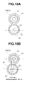
- bearing support 23, 25 is applied with a turning moment about the axis O1 of the first roller, and is made to swing about the axis O1 of the first roller from the position shown in FIG. 10A to the position shown in FIG. 10B .
- bearing support 23, 25 includes no projection 23c, 25c and no projection 23d, 25d for preventing the swinging motion in contrast to the present embodiment
- the swinging motion of bearing support 23, 25 is large so that the displacement of rotation axis O2 of second roller 32 becomes large by addition of a displacement resulting from this swinging motion, as shown in FIG. 10B .
- This displacement of rotation axis O2 of the second roller relates to the offset between front propeller shaft 7 and the rotation axis O2 of the second roller, so that the offset between front propeller shaft 7 and the rotation axis O2 of the second roller is increased.
- bearing support 23, 25 is provided with projection 23c, 25c and projection 23d, 25d for preventing bearing support 23, 25 from swinging about the axis O1 of input shaft 12 (first roller 31)
- bearing support 23, 25 is prevented from swinging about the axis O1 of the first roller, as clearly shown in FIG. 11B , even when second roller 32 is made to revolve about the eccentric axis O3 from a position out of contact with first roller 31 as shown in FIG. 11A to a position in contact with first roller 31 as shown in FIG. 11B , and thereby bearing support 23, 25 is applied with a turning moment about the axis O1 of the first roller.
- the displacement of rotation axis O2 of second roller 32 can be held small as shown in FIG. 11B , because no displacement resulting from this swinging motion of bearing support 23, 25 is added to the displacement of rotation axis O2 of second roller 32. Since this displacement of rotation axis O2 of the second roller relates to the offset between front propeller shaft 7 and the rotation axis O2 of the second roller, it is possible to hold small the offset between front propeller shaft 7 and the rotation axis O2 of the second roller.
- bearing support 23, 25 is provided with projection 23c, 25c and projection 23d, 25d to prevent bearing support 23, 25 from swinging about the axis O1 of input shaft 12 (first roller 31).
- projection 23c, 25c and projection 23d, 25d are configured to be capable of sliding in guide groove 11g, 11h of inner surface 11e, 11f of the housing in the vertical direction as shown in FIG. 3 so that the large extension ⁇ 2 of bearing support 23, 25 toward the second roller side is not prevented.
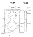
- FIGS. 5 and 6 show the second embodiment of the present invention.
- This embodiment is configured to solve a problem that bending deformation of input shaft 12 causes a radial displacement of first roller 31 as indicated by ⁇ 2 in FIG. 9B in the first embodiment of FIGS. 1 to 4 , and thereby affect adversely, although slightly, the action and effect of the first embodiment.
- first roller 31 radial displacement ⁇ 2 of first roller 31 resulting from bending deformation of input shaft 12 in the first embodiment, with reference to FIG. 12A .
- the radial pressing force between first roller 31 and second roller 32 acts on input shaft 12 through first roller 31, and thereby serves to cause bending deformation of input shaft 12 between ball bearings 14, 15 which serves as bearings to support input shaft 12 with respect to housing 11.
- bearing support 23, 25 there is a clearance between bearing support 23, 25 and inner wall 11a of housing 11 so that bearing support 23, 25 can move in the direction indicated by arrow A1, A2 toward the inner wall 11a, and therefore cannot resist the inter-roller radial pressing force to cause bending deformation of input shaft 12 between ball bearings 14, 15 as described above. Accordingly, bending deformation of input shaft 12 is caused as shown in FIG. 12A , so that first roller 31 is displaced in the radial direction toward the inner wall 11a of the housing by ⁇ 2 due to the bending deformation.
- the radial displacement ⁇ 2 of first roller 31 results in a decrease in the displacement ⁇ 2 of revolution center O3 of the second roller in FIG. 9B , and thereby increases the displacement ⁇ 2 of the rotation axis O2 of the second roller, and thereby affect adversely, although slightly, the action and effect of the first embodiment.
- an end portion of bearing support 23, 25 facing the housing inner wall 11a is provided with a projection 23e, 25e in contact with housing inner wall 11a, although driving force distribution device 1 is configured basically similar to the first embodiment shown in FIGS. 1 to 4 , as shown in FIGS. 5 and 6 .
- projection 23e, 25e prevents bearing support 23, 25 from moving in the direction indicated by arrow A1 or A2 in FIG. 12A by contact with inner wall 11a, and thereby prevents input shaft 12 from being bended between ball bearings 14, 15 by the inter-roller radial pressing force. Accordingly, as shown in FIG. 12B , input shaft 12 is maintained straight substantially without bending deformation due to the inter-roller radial pressing force, so that first roller 31 is prevented from radial displacement indicated by ⁇ 2 in FIG. 12A .
- projection 23e, 25e of this embodiment further functions by contact with housing inner wall 11a to concentrate to the second roller side the extension of bearing support 23, 25 when the inter-roller radial pressing force (inter-roller transmitted torque capacity) is increased.
- the concept of the present invention can be applied to a driving force distribution device not shown in which second roller 32 is rotatably supported about an eccentric shaft portion of a crankshaft that is rotatably supported about eccentric axis O3, and the crankshaft is made to revolve so that second roller 32 revolves from the non-transmission position out of contact with first roller 31 to the transmission position in pressing contact with first roller 31.
- This achieves a similar action and effect naturally.
Landscapes
- Engineering & Computer Science (AREA)
- General Engineering & Computer Science (AREA)
- Mechanical Engineering (AREA)
- Chemical & Material Sciences (AREA)
- Combustion & Propulsion (AREA)
- Transportation (AREA)
- Friction Gearing (AREA)
- Arrangement And Driving Of Transmission Devices (AREA)
Abstract
Description
- The present invention relates to a proposal of improvement of a friction gearing useful as a driving force distribution device, such as a transfer for a four wheel drive vehicle.
- A
patent document 1 discloses a commonly known driving force distribution device. This driving force distribution device is configured to transmit torque through indirect radial pressing contact between a first roller and a second roller with a torque capacity varying according to a state of the inter-roller radial pressing contact. -
Patent document 1 proposes an idea that both of the rollers are supported by a common support plate, and housed in a housing, wherein the support plate bears a reaction force caused by the inter-roller radial pressing contact, and the housing is prevented from being reached by the reaction force.
Patent document 1:JP 2002-349653 A - In order to make a friction gearing of this type capable of varying its transmitted torque capacity, it is necessary to configure the friction gearing to vary the inter-roller radial pressing force. This is implemented by a configuration that one of first and second rollers, for example, the second roller, is made capable of being displaced with respect to the first roller so that the inter-roller radial pressing force can be varied according to the relative radial displacement of the second roller.
- The following considers a situation in which the second roller is made to approach the first roller radially so as to increase the inter-roller radial pressing force (transmitted torque capacity). In this situation, the rotation axis of the second roller approaches the rotation axis of the first roller, and thereby increases an offset from a center of a torque transmitting shaft that transmits torque between the second roller and itself. The increase in the offset causes an increase in a relative radial displacement to be absorbed by a universal coupling between the second roller and the torque transmitting shaft, and thereby serves to adversely affect the durability of a driveline including the universal coupling.
- On the other hand, in the situation in which the second roller is made to approach the first roller radially so as to increase the inter-roller radial pressing force (transmitted torque capacity), the reaction force increases so as to increase an amount of extension of the common rotation support plate due to a stretching force acting on the first roller and the second roller away from each other.
- The increase in the amount of extension of the rotation support plate serves to reduce the offset between the rotation axis of the second roller and the center of the torque transmitting shaft in the situation where the inter-roller transmitted torque capacity is increased. By nature, this serves to reduce the offset (relative radial displacement) that is to be absorbed by the universal coupling between the second roller and the torque transmitting shaft, and thereby enhance the durability of the driveline including the second roller and the torque transmitting shaft.
- However,
patent document 1 and other conventional documents are silent at all about how to arrange the rotation support plate with respect to the housing. If the rotation support plate is attached to a section of the housing between the first roller and the second roller based a common idea without no special idea about arrangement of the rotation support plate with respect to the housing, it is impossible to take full advantage of the function of reducing the increase in the offset between the rotation axis of the second roller and the center of the torque transmitting shaft in the situation where the inter-roller transmitted torque capacity is increased, and thereby enhancing the durability of the driveline, and there is room to improve this point, as described in the following. - Specifically, if the rotation support plate is attached to the section of the housing between the first roller and the second roller, the stretching force acting on the first roller and the second roller away from each other serves to extend the rotation support plate toward the first roller side on one hand, and extend the rotation support plate toward the second roller side on the other hand, so that the amount of extension of the rotation support plate is divided between the first roller side and the second roller side.
- In this connection, only the amount of extension of the rotation support plate toward the second roller side can contribute to the function of reducing the increase in the offset between the rotation axis of the second roller and the center of the torque transmitting shaft, and thereby enhancing the durability of the driveline. Accordingly, if the rotation support plate is attached to the section of the housing between the first roller and the second roller, it is just possible to take half advantage of the function of reducing the increase in the offset between the rotation axis of the second roller and the center of the torque transmitting shaft, and thereby enhancing the durability of the driveline.
- In view of the foregoing, it is an object of the present invention to propose a friction gearing capable of taking full advantage of the function of reducing the increase in the offset between the rotation axis of the second roller and the center of the torque transmitting shaft, and thereby enhancing the durability of the driveline.
- According to one mode of the present invention, a friction gearing comprises: a housing; and a unit housed in the housing, wherein the unit includes a first roller, a second roller and a rotation support plate; wherein: the first and second rollers are configured to perform frictional transmission in radial pressing contact with each other, and vary a state of the radial pressing contact between the first and second rollers by radial displacement of the second roller with respect to the first roller; the rotation support plate is configured to support the first and second rollers, and receive a reaction force caused by the radial pressing contact between the first and second rollers; and the unit is supported in the housing in a manner that the first roller is rotatably supported with respect to the housing with a rotation axis of the first roller restrained radially.
-
-
FIG. 1 is a schematic plan view from above a four wheel drive vehicle, showing a powertrain of the four wheel drive vehicle which is provided with a friction gearing according to a first embodiment of the present invention, wherein the friction gearing is constructed as a driving force distribution device; -
FIG. 2 is a side sectional view of the driving force distribution device ofFIG. 1 ; -
FIG. 3 shows a bearing support employed in the driving force distribution device ofFIG. 2 , whereinFIG. 3A is a front view of the bearing support, andFIG. 3B is a side sectional view of the bearing support; -
FIG. 4 is a sectional view of a crankshaft employed in the driving force distribution device ofFIG. 2 ; -
FIG. 5 is a side sectional view similar toFIG. 2 , showing a driving force distribution device according to a second embodiment of the present invention; -
FIG. 6 shows a bearing support employed in the driving force distribution device ofFIG. 5 , whereinFIG. 6A is a front view of the bearing support, andFIG. 6B is a side sectional view of the bearing support; -
FIG. 7 is a side sectional view similar toFIG. 2 , showing a driving force distribution device which is configured based on a common idea by attaching the bearing support to a midpoint section of the housing in a vertical direction of the housing in the driving force distribution device ofFIG. 2 ; -
FIG. 8 is a diagram showing a situation in which in the driving force distribution device ofFIG. 7 , the bearing support is extended when a second roller is brought from a bottom dead center position to a top dead center position closer to a first roller, whereinFIG. 8A is a diagram showing a condition in which the second roller is in the bottom dead center position, andFIG. 8B is a diagram showing a condition in which the second roller is in the top dead center position; -
FIG. 9 is a diagram showing a situation in which in the driving force distribution device ofFIG. 2 , the bearing support is extended when a second roller is brought from a bottom dead center position to a top dead center position closer to a first roller, whereinFIG. 9A is a diagram showing a condition in which the second roller is in the bottom dead center position, andFIG. 9B is a diagram showing a condition in which the second roller is in the top dead center position; -
FIG. 10A is a diagram showing a situation in which the bearing support swings about a rotation axis of the first roller in the driving force distribution device ofFIG. 7 , specifically showing a condition before swinging of the bearing support; -
FIG. 10B is a diagram showing the situation in which the bearing support swings about the rotation axis of the first roller in the driving force distribution device ofFIG. 7 , specifically showing a condition after swinging of the bearing support; -
FIG. 11A is a diagram showing a situation in which the bearing support swings about a rotation axis of the first roller in the driving force distribution device ofFIG. 2 , specifically showing a condition before swinging of the bearing support; -
FIG. 11B is a diagram showing the situation in which the bearing support swings about the rotation axis of the first roller in the driving force distribution device ofFIG. 2 , specifically showing a condition after swinging of the bearing support; -
FIG. 12A is a diagram showing how an input shaft is deformed by an inter-roller radial pressing force in the first embodiment ofFIGS. 1 to 4 ; -
FIG. 12B is a diagram showing how an input shaft is deformed by an inter-roller radial pressing force in the second embodiment ofFIGS. 5 and6 ; and -
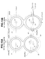
FIG. 13 is a diagram showing a situation in which in the driving force distribution device ofFIG. 5 , the bearing support is extended when a second roller is brought from a bottom dead center position to a top dead center position closer to a first roller, whereinFIG. 13A is a diagram showing a condition in which the second roller is in the bottom dead center position, andFIG. 13B is a diagram showing a condition in which the second roller is in the top dead center position. - <Representative Effect of the Present Invention> A friction gearing according to embodiments of the present invention described below, in which a unit which includes a first roller, a second roller and a rotation support plate is supported in a housing in a manner that the first roller is rotatably supported with respect to the housing with a rotation axis of the first roller restrained radially, can concentrate an amount of extension of the rotation support plate to extension toward a second roller side without dividing same between a first roller side and the second roller side, wherein the amount of extension of the rotation support plate is caused by a stretching force acting on the first roller and the second roller away from each other due to radial pressing contact between the first roller and the second roller, and the entire amount of extension of the rotation support plate becomes an amount of extension of the rotation support plate toward the second roller side.
- Accordingly, when the second roller is made to approach the first roller to increase the inter-roller radial pressing force, it is possible to sufficiently reduce an increase in an offset between a rotation axis of the second roller and a torque transmitting shaft associated with the second roller by the amount of extension of the rotation support plate concentrated to extension toward the second roller side, and thereby reduce the offset (relative radial displacement) that is to be absorbed by a universal coupling between the second roller and the torque transmitting shaft, and thereby enhance the durability of a driveline including the second roller and the torque transmitting shaft.
- The following describes modes for carrying out the present invention in detail with reference to a first embodiment shown in
FIGS. 1 to 4 , and a second embodiment shown inFIGS. 5 and6 .
<Configuration of First Embodiment>FIGS. 1 to 4 show the first embodiment of the present invention.FIG. 1 is a schematic plan view from above a four wheel drive vehicle, showing a powertrain of the four wheel drive vehicle which is provided with a friction gearing according to the first embodiment of the present invention, wherein the friction gearing is constructed as a drivingforce distribution device 1. - The four wheel drive vehicle of
FIG. 1 is based on a rear wheel drive vehicle in which rotation from anengine 2 is shifted by atransmission 3, and then transmitted through arear propeller shaft 4 and a rearfinal drive unit 5 to left and rightrear wheels force distribution device 1 through afront propeller shaft 7 and a frontfinal drive unit 8 to left and right front wheels (auxiliary driving wheels) 9L, 9R, thus achieving four wheel driving. - Driving
force distribution device 1 is thus configured to set torque distribution between left and right rear wheels (main driving wheels) 6L, 6R, and left and right front wheels (auxiliary driving wheels) 9L, 9R by splitting and outputting to left and right front wheels (auxiliary driving wheels) 9L, 9R a part of torque to left and right rear wheels (main driving wheels) 6L, 6R. In this embodiment, drivingforce distribution device 1 is constructed as shown inFIG. 2 . - In
FIG. 2 , aninput shaft 12 and anoutput shaft 13 are arranged to laterally cross in ahousing 11, which are parallel to one another.Input shaft 12 is rotatably supported with respect tohousing 11 byball bearings input shaft 12 about an axis O1. -
Input shaft 12 is rotatably supported also with respect to bearing supports 23, 25 byroller bearings support opening roller bearing FIGS. 3A and 3B . Each bearingsupport input shaft 12 andoutput shaft 13. Each bearingsupport housing 11 in a manner that bearingsupport inner surface housing 11 as shown inFIG. 2 , but is not fixed toinner surface - Both ends of
input shaft 12 are made to extend out ofhousing 11, sealed liquid-tightly byseal rings FIG. 2 ) ofinput shaft 12 is coupled to an output shaft of transmission 3 (seeFIG. 1 ), and the right end (inFIG. 2 ) ofinput shaft 12 is coupled through rear propeller shaft 4 (seeFIG. 1 ) to rearfinal drive unit 5. -
Input shaft 12 is formed integrally with afirst roller 31 substantially at the center ofinput shaft 12 in the axial direction ofinput shaft 12, whereinfirst roller 31 is coaxially arranged withinput shaft 12.Output shaft 13 is formed integrally with asecond roller 32 substantially at the center ofoutput shaft 13 in the axial direction ofoutput shaft 13, whereinsecond roller 32 is coaxially arranged withoutput shaft 13.First roller 31 andsecond roller 32 are arranged in a common plane perpendicular to the axes ofinput shaft 12 andoutput shaft 13. -
Output shaft 13 is rotatably supported with respect tohousing 11 in an indirect manner with the following configuration. Namely,hollow crankshafts second roller 32 that is formed integrally withoutput shaft 13 substantially at the center ofoutput shaft 13 in the axial direction ofoutput shaft 13, andcrankshafts output shaft 13. Both ends ofoutput shaft 13 are fitted in central holes 51La, 51Ra (whose semidiameter is represented by Ri in the drawings) ofcrankshafts Bearings crankshafts output shaft 13, so thatoutput shaft 13 is supported in the central holes 51La, 51Ra ofcrankshafts - As clearly shown in
FIG. 4 ,crankshafts crankshafts bearings support opening FIGS. 3A and 3B . - Each bearing
support input shaft 12 andoutput shaft 13 as described above, and also serves as a common rotation support plate for supporting both offirst roller 31 andsecond roller 32 becausefirst roller 31 andsecond roller 32 are formed integrally withinput shaft 12 andoutput shaft 13, respectively. Each bearingsupport support inner wall 11a ofhousing 11 whereininput shaft 12 is arranged betweeninner wall 11a andoutput shaft 13 as shown inFIGS. 2 and3 , and is out of contact with aninner wall 11d ofhousing 11 whereinoutput shaft 13 is arranged betweeninner wall 11d andinput shaft 12 as shown inFIG. 3 . - Moreover, each bearing
support projection projection support projection projection guide groove inner surface guide groove opening projection -
Crankshafts supports second roller 32, are positioned in the axial direction bythrust bearings FIG. 2 . - As shown in
FIG. 2 , the ends ofcrankshafts crankshaft driving pinion 55, under condition that crankshafts 51L, 51R are in rotational positions such that the eccentric peripheries 51Lb, 51Rb are aligned with one another in the circumferential direction. -
Crankshaft driving pinion 55 is coupled to apinion shaft 56. Both ends ofpinion shaft 56 are rotatably supported with respect tohousing 11 bybearings pinion shaft 56 on the right side ofFIG. 2 is exposed outside ofhousing 11. The exposed end surface ofpinion shaft 56 is drivingly coupled, for example, by serration coupling, to anoutput shaft 45a of an inter-roller pressingforce control motor 45 that is attached tohousing 11. - Accordingly, by controlling the rotational positions of
crankshafts pinion 55 and ring gears 51Lc, 51Rc by inter-roller pressingforce control motor 45, the rotation axis O2 ofoutput shaft 13 andsecond roller 32 revolves along a locus circle α indicated by a broken line inFIG. 4 . The revolution of rotation axis O2 causes a change in an inter-axis distance L1 between the first roller and the second roller (seeFIG. 2 ), and allows to control the radial pressing force fromsecond roller 32 to first roller 31 (inter-roller transmitted torque capacity) arbitrarily between zero and a maximum value. -
Crankshaft 51L andoutput shaft 13 are made to project fromhousing 11 on the left side ofFIG. 2 . At the projecting portions, aseal ring 57 is disposed betweenhousing 11 andcrankshaft 51L, and aseal ring 58 is disposed betweencrankshaft 51L andoutput shaft 13. Seal rings 57, 58 liquid-tightly seal the projecting portions ofcrankshaft 51L andoutput shaft 13 that project fromhousing 11. - The center of the inside periphery and the center of the outside periphery of
crankshaft 51L are set eccentric from one another at its end portion where seal rings 57, 58 are disposed, as at the portion whereoutput shaft 13 is supported.Seal ring 57 is disposed between the outside periphery of the end portion ofcrankshaft 51L andhousing 11, andseal ring 58 is disposed between the inside periphery of the end portion ofcrankshaft 51L andoutput shaft 13. This sealing construction makes it possible to preferably seal the place whereoutput shaft 13 projects fromhousing 11, although the rotation axis O2 ofoutput shaft 13 revolves according to the revolution ofoutput shaft 13. - <Driving Force Distribution Control According To First Embodiment> The following describes a driving force distribution control according to the first embodiment shown in
FIGS. 1 to 4 . On one hand, the torque from transmission 3 (seeFIG. 1 ) to inputshaft 12 is transmitted directly frominput shaft 12 throughrear propeller shaft 4 and rear final drive unit 5 (seeFIG. 1 for both) to left and rightrear wheels - On the other hand, driving
force distribution device 1 according to this embodiment can direct to output shaft 13 a part of torque to left and rightrear wheels first roller 31 andsecond roller 32 , when controlling the rotational position ofcrankshafts pinion 55 and ring gears 51Lc, 51Rc by inter-roller pressingforce control motor 45, and thereby setting the inter-roller-axis distance L1 smaller than the sum of the semidiameters offirst roller 31 andsecond roller 32, because first andsecond rollers - In this connection, during torque transmission, the radial pressing reaction force between
first roller 31 andsecond roller 32 is received by bearingsupports housing 11. This eliminates the necessity of enhancing the strength ofhousing 11 to resist the radial pressing reaction force betweenfirst roller 31 andsecond roller 32, and thereby prevents the weight and cost from being adversely affected. - After the above, the torque is transmitted to left and right front wheels (auxiliary driving wheels) 9L, 9R from the left end (in
FIG. 2 ) ofoutput shaft 13 through front propeller shaft 7 (seeFIG. 1 ) and front final drive unit 8 (seeFIG. 1 ). This allows four wheel driving of the vehicle wherein all of left and right rear wheels (main driving wheels) 6L, 6R and left and right front wheels (auxiliary driving wheels) 9L, 9R are driven. - Incidentally, during inter-roller radial mutually pressing force control (inter-roller transmitted torque capacity control) by inter-roller pressing
force control motor 45, theoutput shaft 13 and second roller 32 (their rotation axis O2) revolve about eccentric axis O3. The displacement of revolution ofoutput shaft 13 and second roller 32 (their rotation axis O2) can be absorbed by a universal coupling connecting theoutput shaft 13 andfront propeller shaft 7 to each other, so that torque transmission to left and right front wheels (auxiliary driving wheels) 9L, 9R is not adversely affected, even without an eccentric coupling. - <Action and Effect of the First Embodiment> However, if the offset between
front output shaft 13 and second roller 32 (their rotation axis O2) andpropeller shaft 7 is large, the relative radial displacement to be absorbed by the universal coupling betweenoutput shaft 13 andfront propeller shaft 7 becomes large, to adversely affect the durability of the driveline including the universal coupling. Accordingly, it is desirable that the offset betweenoutput shaft 13 and second roller 32 (their rotation axis O2) andfront propeller shaft 7 is as small as possible. This demand can be satisfied by the following principle of the driving force distribution device according to the embodiment described above. - Prior to explanation about this principle, the following describes the offset between
output shaft 13 and second roller 32 (their rotation axis O2) andfront propeller shaft 7 for a case in which central sections of bearing supports 23, 25 betweeninput shaft 12 andoutput shaft 13 are fixed toinner surfaces bolts FIG. 2 . - When
second roller 32 is made to approachfirst roller 31 radially to increase the inter-roller radial pressing force (inter-roller transmitted torque capacity), the rotation axis O2 ofsecond roller 32 revolves from a bottom dead center position shown inFIG. 8A to a top dead center position shown inFIG. 8B to approach the rotation axis O1 offirst roller 31, causing an increase in the offset betweenfront propeller shaft 7 and the rotation axis O2 ofsecond roller 32. The increase in the offset causes an increase in the relative radial displacement to be absorbed by the universal coupling betweenoutput shaft 13 andfront propeller shaft 7, and thereby adversely affects the durability of the driveline including the universal coupling. - On the other hand, when
second roller 32 is made to approachfirst roller 31 radially to increase the inter-roller radial pressing force (inter-roller transmitted torque capacity), the reaction force increases, and causes a stretching force acting on thefirst roller 31 andsecond roller 32 away from each other, and thereby increases the amount of extension of bearingsupport - The increase in extension of bearing
support front propeller shaft 7 and rotation axis O2 ofsecond roller 32 when the inter-roller transmitted torque capacity is increased, and suppress the offset (relative radial displacement) that is to be absorbed by the universal coupling betweenoutput shaft 13 andfront propeller shaft 7, and thereby enhance the durability of the driveline including the universal coupling. - However, in the case shown in
FIG. 7 where the central sections of bearing supports 23, 25 are fixed to housinginner surfaces bolts first roller 31 andsecond roller 32 away from each other causes on one hand an extension of bearingsupport FIG. 8B , and thereby displaces rotation axis O1 offirst roller 31 in the same direction by δ1, and causes on the other hand an extension of bearingsupport FIG. 8B , and thereby displaces revolution center O3 ofsecond roller 32 in the same direction by γ1. In this way, the amount of extension of bearingsupport - In this connection, the function of reducing the increase in the offset between
front propeller shaft 7 and rotation axis O2 ofsecond roller 32 when the inter-roller transmitted torque capacity is increased, and thereby enhancing the durability of the driveline, can be achieved only by extension β1 of bearingsupport FIG. 8A to the top dead center position shown inFIG. 8B (namely, only by displacement γ1 of revolution center O3 of the second roller due to this extension β1). - However, in the case shown in
FIG. 7 where the central sections of bearing supports 23, 25 are fixed to housinginner surfaces bolts support FIG. 8A to the top dead center position shown inFIG. 8B . Accordingly, it is only possible to take almost half of advantage of the function of reducing the increase in the offset betweenfront propeller shaft 7 and rotation axis O2 ofsecond roller 32 while utilizing the extension of bearingsupport second roller 32 andfront propeller shaft 7. - In contrast, the driving force distribution device according to the first embodiment shown in
FIGS. 1 to 4 in which the unit is composed as a primary assembly offirst roller 31 includinginput shaft 12,second roller 32 includingoutput shaft 13, and bearingsupport first roller 31 andsecond roller 32, and the unit including the first roller 31 (input shaft 12), second roller 32 (output shaft 13) and thecommon bearing support 23, 25 (as a primary assembly in this embodiment) is supported inhousing 11 by rotatably supportinginput shaft 12 with respect tohousing 11 while restraining theinput shaft 12 in the radial direction byball bearings - Specifically, according to the configuration according to the first embodiment, the rotation axis O1 of
first roller 31 is restrained from being displaced with respect tohousing 11 in the direction away fromsecond roller 32 even with extension of bearingsupport second roller 32 is displaced with respect tohousing 11 in the direction away fromfirst roller 31 due to extension of bearingsupport support first roller 31 andsecond roller 32. In this way, the amount of extension of bearingsupport - Accordingly, the entire amount of extension of bearing
support support
In this way, whensecond roller 32 is made to approachfirst roller 31 to increase the inter-roller radial pressing force (to increase the inter-roller transmitted torque capacity), it is possible to reduce the increase in the offset betweenfront propeller shaft 7 and the rotation axis O2 ofsecond roller 32 by the amount of extension of bearingsupport second roller 32 andfront propeller shaft 7. - The action and effect described above are detailed for a situation as shown in
FIGS. 9A and 9B in whichsecond roller 32 is made to move from a bottom dead center position shown inFIG. 9A radially to a top dead center position shown inFIG. 9B , to approachfirst roller 31, and thereby increase the inter-roller radial pressing force (inter-roller transmitted torque capacity).
In this situation, as clearly shown inFIGS. 9A and 9B , the rotation axis O2 ofsecond roller 32 approaches the rotation axis O1 offirst roller 31, thereby increasing the offset betweenfront propeller shaft 7 and the rotation axis O2 ofsecond roller 32. The increase in the offset causes an increase in the relative radial displacement that is to be absorbed by the universal coupling betweenoutput shaft 13 andfront propeller shaft 7, and thereby serves to adversely affect the durability of the driveline including the universal coupling. - On the other hand, when
second roller 32 is made to approachfirst roller 31 radially to increase the inter-roller radial pressing force (inter-roller transmitted torque capacity) as described above, the reaction force increases, and causes a stretching force acting on thefirst roller 31 andsecond roller 32 away from each other, and thereby increases the amount of extension of bearingsupport - The increase in extension of bearing
support front propeller shaft 7 and rotation axis O2 ofsecond roller 32, and suppress the relative radial displacement that is to be absorbed by the universal coupling betweenoutput shaft 13 andfront propeller shaft 7, and thereby enhance the durability of the driveline including the universal coupling. - In the present embodiment, the rotation axis O1 of
first roller 31 is displaced with a displacement δ2 due to bending deformation ofinput shaft 12 which is described in detail below, but theoretically is not displaced by the extension of bearingsupport second roller 32 is displaced with respect tohousing 11 in the direction away fromfirst roller 31 due to extension of bearingsupport support first roller 31 andsecond roller 32, and is extended only toward the second roller side as indicated by arrow β2 inFIG. 9B , so that the amount of extension of bearingsupport support support FIG. 9B . so that the entire extension of bearingsupport - Accordingly, when
second roller 32 is made to approachfirst roller 31 to increase the inter-roller radial pressing force (inter-roller transmitted torque capacity), displacement γ2 of revolution center O3 of the second roller due to extension of bearingsupport FIG. 9B than γ1 in the conventional case ofFIG. 8B , so that it is possible to sufficiently reduce the displacement ε2 of rotation axis O2 of the second roller by the amount of extension of bearingsupport FIG. 9B when the inter-roller transmitted torque capacity is increased. Accordingly, it is possible to take full advantage of the function of reducing the increase in the offset betweenfront propeller shaft 7 and rotation axis O2 ofsecond roller 32, and thereby enhancing the durability of the driveline betweensecond roller 32 andfront propeller shaft 7. - Moreover, the feature of this embodiment that each bearing
support projection projection projection projection guide groove inner surface support FIG. 3 , can produce the following action and effect. - In this regard, the following describes a problem confronting a case in which bearing
support projection projection second roller 32 is made to revolve about the eccentric axis O3 from a position out of contact withfirst roller 31 as shown inFIG. 10A to a position in contact withfirst roller 31 as shown inFIG. 10B , bearingsupport FIG. 10A to the position shown inFIG. 10B . - In the case in which bearing
support projection projection support second roller 32 becomes large by addition of a displacement resulting from this swinging motion, as shown inFIG. 10B . This displacement of rotation axis O2 of the second roller relates to the offset betweenfront propeller shaft 7 and the rotation axis O2 of the second roller, so that the offset betweenfront propeller shaft 7 and the rotation axis O2 of the second roller is increased. - The increase in the offset between
front propeller shaft 7 and the rotation axis O2 of the second roller becomes large causes an increase in the relative radial displacement to be absorbed by the universal coupling betweenoutput shaft 13 andfront propeller shaft 7, and thereby causes a problem that the durability of the driveline including the universal coupling is adversely affected. - In contrast, in the present embodiment in which bearing
support projection projection bearing support support FIG. 11B , even whensecond roller 32 is made to revolve about the eccentric axis O3 from a position out of contact withfirst roller 31 as shown inFIG. 11A to a position in contact withfirst roller 31 as shown inFIG. 11B , and thereby bearingsupport - Accordingly, the displacement of rotation axis O2 of
second roller 32 can be held small as shown inFIG. 11B , because no displacement resulting from this swinging motion of bearingsupport second roller 32. Since this displacement of rotation axis O2 of the second roller relates to the offset betweenfront propeller shaft 7 and the rotation axis O2 of the second roller, it is possible to hold small the offset betweenfront propeller shaft 7 and the rotation axis O2 of the second roller. - The reduction in the offset between
front propeller shaft 7 and the rotation axis O2 of the second roller leads to a reduction in the relative radial displacement to be absorbed by the universal coupling betweenoutput shaft 13 andfront propeller shaft 7, and thereby serves to solve the problem described above with reference toFIGS. 10A and 10B that the durability of the driveline including the universal coupling is adversely affected. - According to the present embodiment, it is possible to achieve the foregoing action and effect with a simple and inexpensive construction in which bearing
support projection projection support FIG. 9 , becauseprojection projection guide groove inner surface FIG. 3 so that the large extension β2 of bearingsupport - <Second Embodiment>
FIGS. 5 and6 show the second embodiment of the present invention. This embodiment is configured to solve a problem that bending deformation ofinput shaft 12 causes a radial displacement offirst roller 31 as indicated by δ2 inFIG. 9B in the first embodiment ofFIGS. 1 to 4 , and thereby affect adversely, although slightly, the action and effect of the first embodiment. - First, the following describes the radial displacement δ2 of
first roller 31 resulting from bending deformation ofinput shaft 12 in the first embodiment, with reference toFIG. 12A . The radial pressing force betweenfirst roller 31 andsecond roller 32 acts oninput shaft 12 throughfirst roller 31, and thereby serves to cause bending deformation ofinput shaft 12 betweenball bearings input shaft 12 with respect tohousing 11. - In the first embodiment, there is a clearance between bearing
support inner wall 11a ofhousing 11 so that bearingsupport inner wall 11a, and therefore cannot resist the inter-roller radial pressing force to cause bending deformation ofinput shaft 12 betweenball bearings input shaft 12 is caused as shown inFIG. 12A , so thatfirst roller 31 is displaced in the radial direction toward theinner wall 11a of the housing by δ2 due to the bending deformation. - The radial displacement δ2 of
first roller 31 results in a decrease in the displacement δ2 of revolution center O3 of the second roller inFIG. 9B , and thereby increases the displacement ε2 of the rotation axis O2 of the second roller, and thereby affect adversely, although slightly, the action and effect of the first embodiment. - In order to solve this problem, in this embodiment, an end portion of bearing
support inner wall 11a is provided with aprojection inner wall 11a, although drivingforce distribution device 1 is configured basically similar to the first embodiment shown inFIGS. 1 to 4 , as shown inFIGS. 5 and6 . - As shown in
FIG. 12B ,projection support FIG. 12A by contact withinner wall 11a, and thereby preventsinput shaft 12 from being bended betweenball bearings FIG. 12B ,input shaft 12 is maintained straight substantially without bending deformation due to the inter-roller radial pressing force, so thatfirst roller 31 is prevented from radial displacement indicated by δ2 inFIG. 12A . - Accordingly, in a situation as shown in
FIGS. 13A and 13B in whichsecond roller 32 is made to approachfirst roller 31 radially from a bottom dead center position shown inFIG. 13A to a top dead center position shown inFIG. 13B , and thereby increase the inter-roller radial pressing force (inter-roller transmitted torque capacity) under the same condition as inFIGS. 9A and 9B , the feature of this embodiment that the radial displacement δ2 offirst roller 31 due to bending deformation ofinput shaft 12 is substantially equal to zero serves to make the displacement γ3 of revolution center O3 of the second roller larger than γ2 inFIG. 9B , as shown inFIG. 13B , and thereby make the displacement ε3 of rotation axis O2 of the second roller smaller than ε2 inFIG. 9B . This makes further remarkable the action and effect of the first embodiment. - In this connection,
projection inner wall 11a to concentrate to the second roller side the extension of bearingsupport - <Other Embodiment> The first and second embodiments are described above with reference to cases as shown in
FIGS. 2 and5 wheresecond roller 32 is rotatably supported by eccentric holes 52La, 52Ra ofcrankshafts crankshafts second roller 32 revolves from a non-transmission position out of contact withfirst roller 31 to a transmission position in pressing contact withfirst roller 31. Alternatively, the concept of the present invention can be applied to a driving force distribution device not shown in whichsecond roller 32 is rotatably supported about an eccentric shaft portion of a crankshaft that is rotatably supported about eccentric axis O3, and the crankshaft is made to revolve so thatsecond roller 32 revolves from the non-transmission position out of contact withfirst roller 31 to the transmission position in pressing contact withfirst roller 31. This achieves a similar action and effect naturally.
Claims (5)
- A friction gearing comprising:a housing; anda unit housed in the housing, wherein the unit includes a first roller, a second roller and a rotation support plate;wherein:the first and second rollers are configured to perform frictional transmission in radial pressing contact with each other, and vary a state of the radial pressing contact between the first and second rollers by radial displacement of the second roller with respect to the first roller;the rotation support plate is configured to support the first and second rollers, and receive a reaction force caused by the radial pressing contact between the first and second rollers; andthe unit is supported in the housing in a manner that the first roller is rotatably supported with respect to the housing with a rotation axis of the first roller restrained radially.
- The friction gearing as claimed in Claim 1, wherein the rotation support plate is arranged in contact with a portion of an inner wall of the housing, wherein the first roller is located between the portion and the second roller.
- The friction gearing as claimed in Claim 1 or 2, wherein the rotation support plate is arranged in the housing in a manner to restrain swinging motion of the rotation support plate about the rotation axis of the first roller.
- The friction gearing as claimed in Claim 3, wherein the rotation support plate includes a projection projecting in contact with the inner wall of the housing in a manner to prevent swinging motion of the rotation support plate about the rotation axis of the first roller.
- A friction gearing comprising:a housing; anda unit housed in the housing, wherein the unit includes a first roller, a second roller and a rotation support plate;wherein:the first and second rollers are configured to perform frictional transmission in radial pressing contact with each other, and vary a state of the radial pressing contact between the first and second rollers by radial displacement of the second roller with respect to the first roller;the rotation support plate is configured to support the first and second rollers, and receive a reaction force caused by the radial pressing contact between the first and second rollers; andthe unit is supported in the housing in a manner that: the first roller is restrained from being displaced with respect to the housing in a direction away from the second roller by extension of the rotation support plate due to the reaction force; and the second roller is configured to be displaced with respect to the housing in a direction away from the first roller by extension of the rotation support plate due to the reaction force.
Applications Claiming Priority (2)
| Application Number | Priority Date | Filing Date | Title |
|---|---|---|---|
| JP2009054295A JP5326676B2 (en) | 2009-03-07 | 2009-03-07 | Friction transmission |
| PCT/JP2010/052636 WO2010103907A1 (en) | 2009-03-07 | 2010-02-22 | Friction gearing |
Publications (3)
| Publication Number | Publication Date |
|---|---|
| EP2405158A1 true EP2405158A1 (en) | 2012-01-11 |
| EP2405158A4 EP2405158A4 (en) | 2012-06-20 |
| EP2405158B1 EP2405158B1 (en) | 2014-01-08 |
Family
ID=42728198
Family Applications (1)
| Application Number | Title | Priority Date | Filing Date |
|---|---|---|---|
| EP10750661.0A Not-in-force EP2405158B1 (en) | 2009-03-07 | 2010-02-22 | Friction gearing |
Country Status (5)
| Country | Link |
|---|---|
| US (1) | US8944955B2 (en) |
| EP (1) | EP2405158B1 (en) |
| JP (1) | JP5326676B2 (en) |
| CN (1) | CN102341619B (en) |
| WO (1) | WO2010103907A1 (en) |
Families Citing this family (5)
| Publication number | Priority date | Publication date | Assignee | Title |
|---|---|---|---|---|
| JP5817104B2 (en) * | 2010-11-18 | 2015-11-18 | 日産自動車株式会社 | Roller friction transmission unit |
| JP5644455B2 (en) * | 2010-12-09 | 2014-12-24 | 日産自動車株式会社 | Roller friction transmission unit |
| JP5741226B2 (en) * | 2011-06-03 | 2015-07-01 | 日産自動車株式会社 | Friction transmission |
| DE102012100865B4 (en) * | 2012-02-02 | 2016-10-27 | Gkn Driveline International Gmbh | Drive arrangement with electric machine and motor vehicle with such a drive arrangement |
| US20140013902A1 (en) * | 2012-07-10 | 2014-01-16 | Nissan Motor Co., Ltd. | Drive force distributing apparatus |
Family Cites Families (9)
| Publication number | Priority date | Publication date | Assignee | Title |
|---|---|---|---|---|
| DE1212810B (en) * | 1964-06-16 | 1966-03-17 | Martha Helene Kratzsch Geb Mue | Multi-stage friction gear with pressure proportional to the peripheral force |
| DD224378A1 (en) * | 1984-06-06 | 1985-07-03 | Leipzig Drehmaschinen | MULTI-STAGE REIBRAD GEAR |
| JP2002349653A (en) | 2001-05-28 | 2002-12-04 | Nsk Ltd | Friction roller type transmission |
| US6849025B2 (en) * | 2001-04-09 | 2005-02-01 | Nsk Ltd. | Frictional roller transmission |
| JP4407281B2 (en) * | 2003-12-26 | 2010-02-03 | 日産自動車株式会社 | Friction transmission |
| US7441634B2 (en) * | 2003-12-26 | 2008-10-28 | Nissan Motor Co., Ltd. | Friction drive device |
| WO2006009292A1 (en) * | 2004-07-20 | 2006-01-26 | Mikuni Corporation | Power transmission device |
| JP4816093B2 (en) * | 2006-01-16 | 2011-11-16 | 日産自動車株式会社 | Friction transmission |
| JP4694520B2 (en) * | 2007-03-07 | 2011-06-08 | 日産自動車株式会社 | Friction transmission |
-
2009
- 2009-03-07 JP JP2009054295A patent/JP5326676B2/en not_active Expired - Fee Related
-
2010
- 2010-02-22 WO PCT/JP2010/052636 patent/WO2010103907A1/en not_active Ceased
- 2010-02-22 CN CN201080010922.0A patent/CN102341619B/en not_active Expired - Fee Related
- 2010-02-22 US US13/148,540 patent/US8944955B2/en not_active Expired - Fee Related
- 2010-02-22 EP EP10750661.0A patent/EP2405158B1/en not_active Not-in-force
Also Published As
| Publication number | Publication date |
|---|---|
| CN102341619B (en) | 2014-07-02 |
| EP2405158B1 (en) | 2014-01-08 |
| CN102341619A (en) | 2012-02-01 |
| US8944955B2 (en) | 2015-02-03 |
| EP2405158A4 (en) | 2012-06-20 |
| WO2010103907A1 (en) | 2010-09-16 |
| JP2010209953A (en) | 2010-09-24 |
| JP5326676B2 (en) | 2013-10-30 |
| US20120004072A1 (en) | 2012-01-05 |
Similar Documents
| Publication | Publication Date | Title |
|---|---|---|
| EP2236341B1 (en) | Driving force distribution device | |
| EP2405158B1 (en) | Friction gearing | |
| EP2246593B1 (en) | Friction roller type power transmission device | |
| EP2246592B1 (en) | Friction-roller type transmission mechanism | |
| JP5644455B2 (en) | Roller friction transmission unit | |
| JP5176977B2 (en) | Driving force distribution device | |
| JPS63106456A (en) | Toroidal type continuously variable transmission | |
| JP5741226B2 (en) | Friction transmission | |
| JP2000240747A (en) | Electric rotary drive | |
| JP2009047218A (en) | Continuously variable transmission | |
| JP4941279B2 (en) | Friction roller support structure of friction transmission device | |
| JP2009036237A (en) | Continuously variable transmission | |
| JPS61244946A (en) | Stepless speed reduction gear | |
| JP2002021969A (en) | Continuously variable transmission | |
| WO2013183412A1 (en) | Driving force distribution device | |
| WO2013183413A1 (en) | Driving force distribution device | |
| JP2014020379A (en) | Drive force distribution device | |
| JP2006149000A (en) | Electric wheel drive device |
Legal Events
| Date | Code | Title | Description |
|---|---|---|---|
| PUAI | Public reference made under article 153(3) epc to a published international application that has entered the european phase |
Free format text: ORIGINAL CODE: 0009012 |
|
| 17P | Request for examination filed |
Effective date: 20110824 |
|
| AK | Designated contracting states |
Kind code of ref document: A1 Designated state(s): AT BE BG CH CY CZ DE DK EE ES FI FR GB GR HR HU IE IS IT LI LT LU LV MC MK MT NL NO PL PT RO SE SI SK SM TR |
|
| REG | Reference to a national code |
Ref country code: DE Ref legal event code: R079 Ref document number: 602010013008 Country of ref document: DE Free format text: PREVIOUS MAIN CLASS: F16H0013040000 Ipc: F16H0013100000 |
|
| DAX | Request for extension of the european patent (deleted) | ||
| A4 | Supplementary search report drawn up and despatched |
Effective date: 20120521 |
|
| RIC1 | Information provided on ipc code assigned before grant |
Ipc: B60K 17/348 20060101ALI20120514BHEP Ipc: F16H 13/04 20060101ALI20120514BHEP Ipc: F16H 13/10 20060101AFI20120514BHEP |
|
| GRAP | Despatch of communication of intention to grant a patent |
Free format text: ORIGINAL CODE: EPIDOSNIGR1 |
|
| INTG | Intention to grant announced |
Effective date: 20130718 |
|
| GRAS | Grant fee paid |
Free format text: ORIGINAL CODE: EPIDOSNIGR3 |
|
| GRAA | (expected) grant |
Free format text: ORIGINAL CODE: 0009210 |
|
| AK | Designated contracting states |
Kind code of ref document: B1 Designated state(s): AT BE BG CH CY CZ DE DK EE ES FI FR GB GR HR HU IE IS IT LI LT LU LV MC MK MT NL NO PL PT RO SE SI SK SM TR |
|
| REG | Reference to a national code |
Ref country code: GB Ref legal event code: FG4D |
|
| REG | Reference to a national code |
Ref country code: CH Ref legal event code: EP |
|
| REG | Reference to a national code |
Ref country code: IE Ref legal event code: FG4D |
|
| REG | Reference to a national code |
Ref country code: AT Ref legal event code: REF Ref document number: 648951 Country of ref document: AT Kind code of ref document: T Effective date: 20140215 |
|
| REG | Reference to a national code |
Ref country code: DE Ref legal event code: R096 Ref document number: 602010013008 Country of ref document: DE Effective date: 20140220 |
|
| REG | Reference to a national code |
Ref country code: AT Ref legal event code: MK05 Ref document number: 648951 Country of ref document: AT Kind code of ref document: T Effective date: 20140108 |
|
| REG | Reference to a national code |
Ref country code: NL Ref legal event code: VDEP Effective date: 20140108 |
|
| REG | Reference to a national code |
Ref country code: LT Ref legal event code: MG4D |
|
| PG25 | Lapsed in a contracting state [announced via postgrant information from national office to epo] |
Ref country code: IS Free format text: LAPSE BECAUSE OF FAILURE TO SUBMIT A TRANSLATION OF THE DESCRIPTION OR TO PAY THE FEE WITHIN THE PRESCRIBED TIME-LIMIT Effective date: 20140508 Ref country code: NO Free format text: LAPSE BECAUSE OF FAILURE TO SUBMIT A TRANSLATION OF THE DESCRIPTION OR TO PAY THE FEE WITHIN THE PRESCRIBED TIME-LIMIT Effective date: 20140408 Ref country code: LT Free format text: LAPSE BECAUSE OF FAILURE TO SUBMIT A TRANSLATION OF THE DESCRIPTION OR TO PAY THE FEE WITHIN THE PRESCRIBED TIME-LIMIT Effective date: 20140108 |
|
| PG25 | Lapsed in a contracting state [announced via postgrant information from national office to epo] |
Ref country code: SE Free format text: LAPSE BECAUSE OF FAILURE TO SUBMIT A TRANSLATION OF THE DESCRIPTION OR TO PAY THE FEE WITHIN THE PRESCRIBED TIME-LIMIT Effective date: 20140108 Ref country code: ES Free format text: LAPSE BECAUSE OF FAILURE TO SUBMIT A TRANSLATION OF THE DESCRIPTION OR TO PAY THE FEE WITHIN THE PRESCRIBED TIME-LIMIT Effective date: 20140108 Ref country code: PT Free format text: LAPSE BECAUSE OF FAILURE TO SUBMIT A TRANSLATION OF THE DESCRIPTION OR TO PAY THE FEE WITHIN THE PRESCRIBED TIME-LIMIT Effective date: 20140508 Ref country code: AT Free format text: LAPSE BECAUSE OF FAILURE TO SUBMIT A TRANSLATION OF THE DESCRIPTION OR TO PAY THE FEE WITHIN THE PRESCRIBED TIME-LIMIT Effective date: 20140108 Ref country code: CY Free format text: LAPSE BECAUSE OF FAILURE TO SUBMIT A TRANSLATION OF THE DESCRIPTION OR TO PAY THE FEE WITHIN THE PRESCRIBED TIME-LIMIT Effective date: 20140108 Ref country code: FI Free format text: LAPSE BECAUSE OF FAILURE TO SUBMIT A TRANSLATION OF THE DESCRIPTION OR TO PAY THE FEE WITHIN THE PRESCRIBED TIME-LIMIT Effective date: 20140108 Ref country code: NL Free format text: LAPSE BECAUSE OF FAILURE TO SUBMIT A TRANSLATION OF THE DESCRIPTION OR TO PAY THE FEE WITHIN THE PRESCRIBED TIME-LIMIT Effective date: 20140108 |
|
| PG25 | Lapsed in a contracting state [announced via postgrant information from national office to epo] |
Ref country code: HR Free format text: LAPSE BECAUSE OF FAILURE TO SUBMIT A TRANSLATION OF THE DESCRIPTION OR TO PAY THE FEE WITHIN THE PRESCRIBED TIME-LIMIT Effective date: 20140108 Ref country code: BE Free format text: LAPSE BECAUSE OF FAILURE TO SUBMIT A TRANSLATION OF THE DESCRIPTION OR TO PAY THE FEE WITHIN THE PRESCRIBED TIME-LIMIT Effective date: 20140108 Ref country code: LV Free format text: LAPSE BECAUSE OF FAILURE TO SUBMIT A TRANSLATION OF THE DESCRIPTION OR TO PAY THE FEE WITHIN THE PRESCRIBED TIME-LIMIT Effective date: 20140108 |
|
| REG | Reference to a national code |
Ref country code: CH Ref legal event code: PL |
|
| REG | Reference to a national code |
Ref country code: DE Ref legal event code: R097 Ref document number: 602010013008 Country of ref document: DE |
|
| PG25 | Lapsed in a contracting state [announced via postgrant information from national office to epo] |
Ref country code: CH Free format text: LAPSE BECAUSE OF NON-PAYMENT OF DUE FEES Effective date: 20140228 Ref country code: MC Free format text: LAPSE BECAUSE OF FAILURE TO SUBMIT A TRANSLATION OF THE DESCRIPTION OR TO PAY THE FEE WITHIN THE PRESCRIBED TIME-LIMIT Effective date: 20140108 Ref country code: CZ Free format text: LAPSE BECAUSE OF FAILURE TO SUBMIT A TRANSLATION OF THE DESCRIPTION OR TO PAY THE FEE WITHIN THE PRESCRIBED TIME-LIMIT Effective date: 20140108 Ref country code: LI Free format text: LAPSE BECAUSE OF NON-PAYMENT OF DUE FEES Effective date: 20140228 Ref country code: RO Free format text: LAPSE BECAUSE OF FAILURE TO SUBMIT A TRANSLATION OF THE DESCRIPTION OR TO PAY THE FEE WITHIN THE PRESCRIBED TIME-LIMIT Effective date: 20140108 Ref country code: EE Free format text: LAPSE BECAUSE OF FAILURE TO SUBMIT A TRANSLATION OF THE DESCRIPTION OR TO PAY THE FEE WITHIN THE PRESCRIBED TIME-LIMIT Effective date: 20140108 Ref country code: DK Free format text: LAPSE BECAUSE OF FAILURE TO SUBMIT A TRANSLATION OF THE DESCRIPTION OR TO PAY THE FEE WITHIN THE PRESCRIBED TIME-LIMIT Effective date: 20140108 |
|
| PLBE | No opposition filed within time limit |
Free format text: ORIGINAL CODE: 0009261 |
|
| STAA | Information on the status of an ep patent application or granted ep patent |
Free format text: STATUS: NO OPPOSITION FILED WITHIN TIME LIMIT |
|
| PG25 | Lapsed in a contracting state [announced via postgrant information from national office to epo] |
Ref country code: PL Free format text: LAPSE BECAUSE OF FAILURE TO SUBMIT A TRANSLATION OF THE DESCRIPTION OR TO PAY THE FEE WITHIN THE PRESCRIBED TIME-LIMIT Effective date: 20140108 Ref country code: SK Free format text: LAPSE BECAUSE OF FAILURE TO SUBMIT A TRANSLATION OF THE DESCRIPTION OR TO PAY THE FEE WITHIN THE PRESCRIBED TIME-LIMIT Effective date: 20140108 |
|
| REG | Reference to a national code |
Ref country code: IE Ref legal event code: MM4A |
|
| 26N | No opposition filed |
Effective date: 20141009 |
|
| REG | Reference to a national code |
Ref country code: DE Ref legal event code: R097 Ref document number: 602010013008 Country of ref document: DE Effective date: 20141009 |
|
| PG25 | Lapsed in a contracting state [announced via postgrant information from national office to epo] |
Ref country code: IE Free format text: LAPSE BECAUSE OF NON-PAYMENT OF DUE FEES Effective date: 20140222 |
|
| PG25 | Lapsed in a contracting state [announced via postgrant information from national office to epo] |
Ref country code: SI Free format text: LAPSE BECAUSE OF FAILURE TO SUBMIT A TRANSLATION OF THE DESCRIPTION OR TO PAY THE FEE WITHIN THE PRESCRIBED TIME-LIMIT Effective date: 20140108 |
|
| REG | Reference to a national code |
Ref country code: FR Ref legal event code: PLFP Year of fee payment: 7 |
|
| PG25 | Lapsed in a contracting state [announced via postgrant information from national office to epo] |
Ref country code: MT Free format text: LAPSE BECAUSE OF FAILURE TO SUBMIT A TRANSLATION OF THE DESCRIPTION OR TO PAY THE FEE WITHIN THE PRESCRIBED TIME-LIMIT Effective date: 20140108 |
|
| PG25 | Lapsed in a contracting state [announced via postgrant information from national office to epo] |
Ref country code: SM Free format text: LAPSE BECAUSE OF FAILURE TO SUBMIT A TRANSLATION OF THE DESCRIPTION OR TO PAY THE FEE WITHIN THE PRESCRIBED TIME-LIMIT Effective date: 20140108 |
|
| PG25 | Lapsed in a contracting state [announced via postgrant information from national office to epo] |
Ref country code: IT Free format text: LAPSE BECAUSE OF FAILURE TO SUBMIT A TRANSLATION OF THE DESCRIPTION OR TO PAY THE FEE WITHIN THE PRESCRIBED TIME-LIMIT Effective date: 20140108 Ref country code: GR Free format text: LAPSE BECAUSE OF FAILURE TO SUBMIT A TRANSLATION OF THE DESCRIPTION OR TO PAY THE FEE WITHIN THE PRESCRIBED TIME-LIMIT Effective date: 20140409 Ref country code: BG Free format text: LAPSE BECAUSE OF FAILURE TO SUBMIT A TRANSLATION OF THE DESCRIPTION OR TO PAY THE FEE WITHIN THE PRESCRIBED TIME-LIMIT Effective date: 20140108 |
|
| PG25 | Lapsed in a contracting state [announced via postgrant information from national office to epo] |
Ref country code: LU Free format text: LAPSE BECAUSE OF NON-PAYMENT OF DUE FEES Effective date: 20140222 Ref country code: TR Free format text: LAPSE BECAUSE OF FAILURE TO SUBMIT A TRANSLATION OF THE DESCRIPTION OR TO PAY THE FEE WITHIN THE PRESCRIBED TIME-LIMIT Effective date: 20140108 Ref country code: HU Free format text: LAPSE BECAUSE OF FAILURE TO SUBMIT A TRANSLATION OF THE DESCRIPTION OR TO PAY THE FEE WITHIN THE PRESCRIBED TIME-LIMIT; INVALID AB INITIO Effective date: 20100222 |
|
| REG | Reference to a national code |
Ref country code: FR Ref legal event code: PLFP Year of fee payment: 8 |
|
| REG | Reference to a national code |
Ref country code: FR Ref legal event code: PLFP Year of fee payment: 9 |
|
| PG25 | Lapsed in a contracting state [announced via postgrant information from national office to epo] |
Ref country code: MK Free format text: LAPSE BECAUSE OF FAILURE TO SUBMIT A TRANSLATION OF THE DESCRIPTION OR TO PAY THE FEE WITHIN THE PRESCRIBED TIME-LIMIT Effective date: 20140108 |
|
| PGFP | Annual fee paid to national office [announced via postgrant information from national office to epo] |
Ref country code: GB Payment date: 20200212 Year of fee payment: 11 Ref country code: DE Payment date: 20200211 Year of fee payment: 11 |
|
| PGFP | Annual fee paid to national office [announced via postgrant information from national office to epo] |
Ref country code: FR Payment date: 20200113 Year of fee payment: 11 |
|
| REG | Reference to a national code |
Ref country code: DE Ref legal event code: R119 Ref document number: 602010013008 Country of ref document: DE |
|
| GBPC | Gb: european patent ceased through non-payment of renewal fee |
Effective date: 20210222 |
|
| PG25 | Lapsed in a contracting state [announced via postgrant information from national office to epo] |
Ref country code: DE Free format text: LAPSE BECAUSE OF NON-PAYMENT OF DUE FEES Effective date: 20210901 Ref country code: GB Free format text: LAPSE BECAUSE OF NON-PAYMENT OF DUE FEES Effective date: 20210222 Ref country code: FR Free format text: LAPSE BECAUSE OF NON-PAYMENT OF DUE FEES Effective date: 20210228 |