EP2404521A1 - Slider for slide fastener - Google Patents
Slider for slide fastener Download PDFInfo
- Publication number
- EP2404521A1 EP2404521A1 EP09841117A EP09841117A EP2404521A1 EP 2404521 A1 EP2404521 A1 EP 2404521A1 EP 09841117 A EP09841117 A EP 09841117A EP 09841117 A EP09841117 A EP 09841117A EP 2404521 A1 EP2404521 A1 EP 2404521A1
- Authority
- EP
- European Patent Office
- Prior art keywords
- pull tab
- section
- sections
- slider
- arm
- Prior art date
- Legal status (The legal status is an assumption and is not a legal conclusion. Google has not performed a legal analysis and makes no representation as to the accuracy of the status listed.)
- Granted
Links
Images




Classifications
-
- A—HUMAN NECESSITIES
- A44—HABERDASHERY; JEWELLERY
- A44B—BUTTONS, PINS, BUCKLES, SLIDE FASTENERS, OR THE LIKE
- A44B19/00—Slide fasteners
- A44B19/24—Details
- A44B19/26—Sliders
- A44B19/262—Pull members; Ornamental attachments for sliders
Definitions
- the invention relates to a slider including a pull tab that opens and closes a slide fastener, and more particularly, to a slider of which a pull tab can be removed when the slider is not operated.
- a pull tab which is held by a user when the user moves a slider, has been mounted on the slider that opens and closes a slide fastener in the related art.
- a shaft portion of the pull tab is inserted between front and rear column sections standing on the upper surface of the slider body.
- a cover covers the column sections so that the upper side between the column sections is closed.
- a bearing hole is formed by swaging the cover to the column sections. In this way, a pull tab shaft section is loosely fitted to the bearing hole, so that the pull tab is tiltably supported relative to the slider body.
- the slider body and the pull tab should be separated from each other thereafter.
- Patent Document 1 a slider where a pull tab can be removed so that the pull tab is replaced according to user's taste is disclosed in Japanese Patent Application Publication No. 7-55161 (Patent Document 1).
- a pull tab mounting lever which includes a bearing hole to which a pull tab shaft section is loosely fitted, stands on an upper surface of a slider body disclosed in Patent Document 1.
- the pull tab mounting lever extends toward the rear end of the slider body, and includes a rear end protruding portion that closes about the upper half of the bearing hole.
- a gap portion through which the pull tab shaft section can pass is formed between the rear end protruding portion and the upper surface of the slider body. Accordingly, when being observed in a lateral direction, the pull tab mounting lever has the shape of a hook.
- a closing body which can slide in the front-back direction of the slider body, is disposed at a gap portion, which is formed between the upper surface of a rear portion of the slider body and the lower side of the rear end protruding portion of the pull tab mounting lever.
- a sliding protrusion is formed at the closing body.
- the pull tab shaft section escapes to the upper side of the bearing hole, so that the closing body pushed toward the front side of the slider body is separated and becomes free. Accordingly, the sliding protrusion is pushed to the position facing the rear end protruding portion of the pull tab mounting lever, so that the gap portion is closed. Since the gap portion is closed in this state, the pull tab shaft section is not separated from the bearing hole even though the pull tab is operated in any manner.
- the pull tab which is mounted once, can be removed.
- the slider body is held first, there is prepared a specialized tool of which the tip is thin and strong and which is made of metal, and the closing body is pushed toward the front side of the slider body so as to be slid. Accordingly, a gap portion through which the pull tab shaft section can pass is formed between the rear end protruding portion of the pull tab mounting lever and the upper surface of the slider body. It is possible to take out the pull tab from the slider body by making the pull tab shaft section pass through the gap portion while maintaining this state.
- a temporary pull tab which is easily removed for replacement, is used in the slider disclosed in Patent Document 1.
- a tip portion of the temporary pull tab is formed in an annular shape, and a weak portion, which can be broken, is formed at a part of an annular portion.
- an operation for holding a tab section of the temporary pull tab and twisting the tab section relative to the slider body is performed.
- the weak portion of the pull tab shaft section is broken first. If the tab section of the temporary pull tab is further twisted, the broken weak portion is separated. It is possible to take out the pull tab shaft section from the bearing hole and to simply and quickly remove the temporary pull tab from the slider body by making the pull tab mounting lever pass through the separated portion.
- a slider where a pull tab is adapted to be freely attached to or detached from a slider body is disclosed in Japanese Utility Model Application Laid-Open No. 64-43706 (Patent Document 2).
- Patent Document 2 pull tab shaft sections of the pull tab are formed to protrude from left and right sides and a gap w is formed at the center of the pull tab shaft sections.
- a ⁇ -shaped pull tab mounting lever which is formed of a thin plate having a thickness smaller than the gap w and where bearing holes are formed at both side walls is provided at the upper portion of the slider body.
- one pull tab shaft section is inserted through the bearing hole formed at the side wall of the pull tab mounting lever and a portion of the pull tab shaft section corresponding to the gap w is inserted through one side wall of the pull tab mounting lever.
- the pull tab is inverted like a puzzle ring and the opposite pull tab shaft section is inserted through the opposite bearing hole. In this way, both the pull tab shaft sections can be inserted through the bearing holes that are formed at both the side walls of the pull tab mounting lever.
- the pull tab is adapted to be capable of being removed using a reverse procedure.
- annular pull tab shaft section is broken at both the weak portion and another portion except for the weak portion, broken pieces separated due to this breakage are generated. Further, there is a problem in that much time and effort of a worker are required to collect the broken and separated pieces. Furthermore, if a high stiffness material is used for the pull tab or the shape of the pull tab is to be changed to a shape having high stiffness in order to prevent excessive bending from occurring at the pull tab by a force applied to the pull tab when the slider is made to be slid, large stress is applied to the annular portion including the pull tab shaft section. Accordingly, there is caused a problem that breakage is apt to occur even at portions other than the weak portion.
- the invention has been made in consideration of the above-mentioned problems, and an object of the invention is to provide a slider where a pull tab can be removed from a slider body by the separation of a part of a pull tab shaft section and the generation of broken pieces can be prevented by the prevention of the breakage of other portions of the pull tab even when a part of a pull tab shaft section is separated.
- a slider for a slide fastener includes a slider body and a pull tab.
- the slider body includes column sections on an upper surface thereof and the column sections form a bearing hole where the pull tab is tiltably supported.
- the pull tab includes a pull tab shaft section and a tab section.
- the pull tab shaft section is formed at one end of the pull tab and is to be inserted through the bearing hole.
- the tab section extends from both ends of the pull tab shaft section toward the other end of the pull tab through a pair of left and right symmetrical arm sections.
- a reference inner dimension between opposed inner surfaces of the bearing hole is denoted by A
- the width of the column section is denoted by Z
- a loosely fitting outer dimension of the pull tab shaft section is denoted by a
- a projecting dimension of a pair of engaging projecting sections that is formed at both ends of the pull tab shaft section so as to be symmetric in the left and right is denoted by b
- a range, which has the loosely fitting outer dimension a and is a distance between the engaging projecting sections is defined as a loosely fitting range z
- the maximum inner dimension between the arm sections is denoted by j, b > A > a and j > z > Z are satisfied.
- a center of the loosely fitting range z of the pull tab shaft section forms a separable section that can be separated from each other.
- another invention is characterized in that the width Z of the column section, the loosely fitting range z, and the maximum inner dimension j between the arm sections may satisfy z ⁇ 1.5 ⁇ Z and j > 2 ⁇ Z,
- Another invention is characterized in that when the width of each of the arm sections at a portion, which corresponds to the maximum inner dimension j between the arm sections, is denoted by d, j + d > 3 ⁇ Z may be satisfied.
- another invention is characterized in that when the length of the arm section is denoted by 1, the length 1 of the arm section is 8 (mm) or more, the width d of the arm section is 1.2 (mm) or less, and the maximum inner dimension j between the arm sections is 7 (mm) or more.
- another invention is characterized in that a weak portion, which connects the left and right pull tab shaft sections so as to be breakable, is formed at the separable section.
- the slider according to the invention includes a bearing hole with a reference inner dimension A which is formed at the column sections standing on the upper surface of the slider body and in which a pull tab is tiltably supported.
- Left-right symmetrical engaging projecting sections with the projecting dimension b larger than the reference inner dimension A are formed at both ends of the pull tab shaft section that is inserted through the bearing hole.
- the loosely fitting range z which is the distance between the engaging projecting sections, is set to be larger than the width Z of the column section of the slider body and smaller than the maximum inner dimension j between the arm sections of the pull tab.
- the separable section is formed at the center of the loosely fitting range z of the pull tab shaft section.
- tensile stress and shear stress which are applied to both the arm sections of the pull tab, be substantially symmetric when twisting the pull tab to remove the pull tab from the slider body. Furthermore, when removing the pull tab from the slider body by separating the separable section, it is possible to reduce a trouble that breakage occurs due to large stress applied to one arm section.
- the loosely fitting range z which is the distance between the engaging projecting sections, is set to be larger than the width Z of the column section and smaller than 1.5 times of the width Z of the column section, and the maximum inner dimension j between the arm sections is set to be larger than 2 times of the width Z of the column section.
- the distance between the arm sections is set to be 3 times or more of the width Z of the column section. Accordingly, when removing the pull tab from the slider body by separating the separable section, it is possible to reduce shear stress applied to the arm section and to reduce a trouble that breakage occurs at the arm section.
- the length 1 of the arm section is 8 (mm) or more
- the width d of the arm section is 1.2 (mm) or less
- the maximum inner dimension j between the arm sections is 7 (mm) or more. Accordingly, when removing the pull tab from the slider body by separating the separable section, it is possible to reduce shear stress applied to the arm section and to reduce a trouble that breakage occurs at the arm section.
- the left and right pull tab shaft sections are connected to each other at the separable section so as to be breakable. Accordingly, when sliding the slider with a large operation force, it is possible to reduce a trouble that the pull tab is twisted and separated from the slider body.
- FIG. 1 is a plan view of a slider 50 according to the invention when observed from above.
- FIG. 2 is a plan view of a single pull tab 59 that is mounted on the slider 50 shown in FIG. 1 .
- FIG. 3 is a front view of the slider 50 shown in FIG. 1 when observed from a rear mouth side of the slider 50.
- the front side of the slider 50 is defined as an FS direction shown in FIG. 1 and the rear side of the slider is defined as an RS direction shown in FIG. 1 .
- the left side of the slider 50 is defined as an L direction shown in FIGS. 1 to 3 and the right side of the slider is defined as an R direction shown in FIGS. 1 and 3 .
- the upper side of the slider 50 is defined as a U direction shown in FIG. 3 and the lower side of the slider is defined as a D direction shown in FIG. 3 .
- directions are defined in the same manner as described above.
- the slider 50 includes a slider body 50A and a pull tab 59.
- a connecting column 50D stands up (in the U direction shown in FIG. 3 ) at the central portion of a lower wing piece 53 that forms the bottom portion of the slider body 50A.
- an upper wing piece 52 which is formed substantially parallel to the lower wing piece 53, is formed at the upper portion of the connecting column 50D.
- Two front column sections 56F and two rear column sections 56R, that is, four column sections stand on the upper surface of the upper wing piece 52.
- the front and rear column sections 56F and 56R provided on the upper surface of the slider body 50A are four columns that stand vertically indepently from each other.
- a pull tab shaft section 59K which is formed at the central portion of one end of the pull tab 59, is inserted between the front and rear column sections 56F and 56R, a cover 58 is disposed and swaged at a predetermined position on the front and rear column sections 56F and 56R, so that the upper portions of the front and rear column sections 56F and 56R are closed.
- a bearing hole 56A which has a square inner shape, is formed.
- the pull tab shaft section 59K is loosely fitted to the bearing hole, so that the pull tab 59 is tiltably supported.
- Flanges 50F are erect upward (in the U direction shown in FIG. 3 ) from left and right side edges of the lower wing piece 53 of the slider body 50A, respectively. Further, flanges 50F are erect downward (in the D direction shown in FIG. 3 ) from left and right side edges of the upper wing piece 52, respectively.
- Y-shaped spaces which are surrounded by the upper surface of the lower wing piece 53, both left and right side surfaces of the connecting column 50D, the lower surface of the upper wing piece 52, and the respective flanges 50F, are zipper teeth guide passages through which zipper teeth rows attached to left and right fastener stringers are inserted.
- Gaps which are formed between the flanges 50F that are erect from the left and right side edges of the upper and lower wing pieces 52 and 53, respectively, are tape insertion passages through which left and right fastener tapes of a slide fastener are inserted.
- the near side of the connecting column 50D shown in FIG. 3 (the RS direction in the plan view shown in FIG. 1 ) forms the shape of a sharp wedge of which surfaces are joined to each other from the left and right sides.
- the slider 50 is made to be slid to the near side shown in FIG. 3 (in the RS direction in the plan view shown in FIG. 1 ) while the left and right zipper teeth rows attached to the slide fastener are inserted through the zipper teeth guide passages, the left and right zipper teeth rows coupled to each other are introduced from the rear mouth of the slider 50.
- the zipper teeth rows coupled to each other are separated from each other in the zipper teeth guide passages in a left-right direction by the connecting column 50D that is provided at the central portion, the zipper teeth rows are discharged from both shoulder mouths of the back side shown in FIG. 3 (the FS direction in the plan view shown in FIG. 1 ). Meanwhile, the shoulder mouths mean openings that are surrounded by the side surfaces of the connecting column 50D, the upper wing piece 52, and the lower wing piece 53.
- the zipper teeth rows decoupled from each other are introduced from both the shoulder mouths of the slider 50 and the left and right zipper teeth rows are guided along the flanges 50F and jointed to each other. Accordingly, the left and right zipper teeth rows are coupled to each other and are then discharged from the rear mouth of the slider 50 on the near side shown in FIG. 3 (in the RS direction in the plan view shown in FIG. 1 ).
- the pull tab shaft section 59K which is inserted through the bearing hole 56A is formed at the central portion of one end of the pull tab 59 which is loosely fitted to the slider 50, and a pair of engaging projecting sections 59H, which has a dimension incapable of being inserted through the bearing hole 56A and is symmetric in the left and right, is formed at both ends of the pull tab shaft section 59K.
- an opening which has a rectangular shape in plan view, is formed at the tab section of the pull tab 59.
- a range which has the loosely fitting outer dimension a and is the distance between the engaging projecting sections 59H, is defined as a loosely fitting range z;
- the maximum inner dimension between the arm sections 59A is denoted by j;
- the width of the arm section 59A at a portion, which corresponds to the maximum inner dimension j between the arm sections, in the left-right direction is denoted by d;
- the distance between the left and right arm sections 59A is denoted by n.
- the cross-sectional shape of the arm section 59A is a circular shape in embodiments shown in FIGS. 2 , 6 , 7 , 8 , and 10 .
- the cross-sectional shape of the arm section 59A is not limited to the circular shape, and may be other shapes, such as an oval shape and a rectangular shape.
- the loosely fitting outer dimension a of the pull tab shaft section 59K is set to be smaller than the reference inner dimension A between the opposed inner surfaces of the bearing hole 56A, and the loosely fitting range z is set to be larger than the width Z of each of the front and rear column sections 56F and 56R of the slider body 50A. Accordingly, it is possible to loosely fit the pull tab shaft section 59K to the bearing hole 56A, and to support the pull tab 59 so that the pull tab can be tilted in the front-back direction of the slider body 50A.
- the projecting dimension b of the pair of left and right engaging projecting section 59H of the pull tab 59 is set to be larger than the reference inner dimension A between the opposed inner surfaces of the bearing hole 56A. Accordingly, it is possible to prevent a trouble that the bearing hole 56A turns up to the portion corresponding to the maximum inner dimension j between the arm sections j which is set to be larger than the loosely fitting range z, and the pull tab 59 is significantly rotated along the bearing hole 56A of the slider body 50A.
- front and rear column sections 56F and 56R having the width Z of the column section are interposed between the engaging projecting sections 59H that are formed at both ends of the pull tab shaft section 59K, so that it is possible to always hold the separable section 59B at the central portion of the bearing hole 56A. Accordingly, when a user twists the pull tab 59 to remove the pull tab 59 from the slider body 50A, it is possible to maintain the bending or twist of the left and right arm sections 59A uniform.
- the loosely fitting range z be set to be smaller than 1.5 times of the width Z of the column section.
- a separable section 59B which can be separated from each other, is formed at the center of the loosely fitting range z of the pull tab shaft section 59K.
- the left and right pull tab shaft sections 59K are connected to each other at the separable section 59B and the cross-sectional area of a portion, which forms the separable section 59B, is much smaller than that of the pull tab shaft section 59K.
- the loosely fitting outer dimension a of the pull tab shaft section 59K is an outer diameter of 0,8 (mm)
- the outer diameter of the separable section 59B may be set in the range of about 0.3 (mm) to 0.4 (mm)
- a part of the separable section 59B is formed to be thin as described above so that the cross-sectional area of the part of the separable section 59B is small, a part of the separable section 59B is broken first when the pull tab 59 is twisted relative to the slider body 50A. After that, if the pull tab 59 continues to be twisted, it is possible to remove the pull tab 59 from the slider body 50A. Meanwhile, the left and right pull tab shaft sections 59K are connected to each other at the separable section 59B in an initial state. Accordingly, even when sliding the slider 50 with a large operation force, it is possible to reduce a trouble that the pull tab 59 is separated from the slider body 50A.
- the slide fastener is used to close an opening formed at a seat cover that covers the surface of an automobile seat and is made of fabric, leather, or the like.
- Seat springs or cushioning materials are received in the automobile seat and the seat cover presses these elastic members, so that wrinkles are not formed on the surface of the seat cover. In this case, large tension is applied to the seat cover.
- the slider 50 When cushioning materials are covered with the seat cover from above and the separated slide fastener is closed in a process of assembling the automobile seat, the slider 50 is made to be slid, so that the slider closes the slide fastener while compressing the cushioning materials, In this case, in order to resist a force that compresses the cushioning materials, it is necessary to slide the slider 50 while applying a force of about 15 kgf to the slider 50. In order to secure operability in this case, it is preferable to make the pull tab 59 of the slider 50 large so that a user easily holds the pull tab 59 and to increase the breaking strength of the separable section 59B to some degree so that the pull tab 59 is not separated from the slider body 50A by a force applied during operation.
- the pull tab 59 may be removed after an operation for closing the opening of the seat cover is performed first. If the pull tab 59 is mounted on the slider body 50A, the slider body 50A and the pull tab 59 intermittently and repeatedly collide with each other due to vibration generated during travel. For this reason, noise is generated. In order to prevent the generation of the noise, it may be preferable to remove the pull tab 59 from the slider body 50A after the seat cover is closed.
- the pull tab 59 can adequately endure a required operation force of the slider 50 during normal use and can be simply removed from the slider body 50A by being twisted when removing the pull tab 59 from the slider body 50A.
- the maximum inner dimension j between the arm sections 59A is set to be larger than the loosely fitting range z that is the distance between the engaging projecting sections 59H, it is possible to reduce an operation force that is required for breaking the separable section 59B by twisting the pull tab 59 relative to the slider body 50A. Further, it is possible to easily remove the pull tab 59 from the slider body 50A by continuing to reduce an operation force when the pull tab 59 is twisted.
- the maximum inner dimension j between the arm sections is set to be large, it is possible to open the separable section 59B up to the width Z of the column section with a small twist angle. Accordingly, it is possible to easily remove the pull tab 59 from the slider body 50A and to reduce the breakage of the arm section 59A by preventing excessive stress from being applied to the arm section 59A.
- the maximum inner dimension j between the arm sections be set to exceed 2 times of the width Z of the column section.
- a value of the sum of the maximum inner dimension j between the arm sections and the width d of the arm section be set to exceed 3 times of the width Z of the column section. That is, it is preferable that the maximum inner dimension j between the arm sections be set to be large and the width d of the arm section be set as small as possible in a range where a force applied to slide the slider 50 is endured.
- the length of the pull tab 59 to be easily used is about 20 to 30 (mm).
- the width Z of the column section is generally set in the range of about 2.5 to 3 (nm). Accordingly, when the length of the arm section 59A is denoted by 1, it is preferable that the length 1 of the arm section be 8 (mm) or more, the width d of the arm section be 1.2 (mm) or less, and the maximum inner dimension j between the arm sections be 7 (mm) or more.
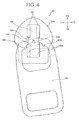
- FIG. 4 is a plan view showing a state where the engaging projecting section 59H comes into contact with the side wall of the rear column section 56R and the rotation of the pull tab 59 is thus limited when the pull tab 59 is rotated in the horizontal plane of the slide fastener.
- FIG. 5 is a plan view showing a state where the engaging projecting section 59H comes into contact with the side portion of the cover 58 and the rotation of the pull tab 59 is thus limited when the pull tab 59 is rotated in the vertical plane of the slide fastener.
- the same members as the members, which have been described in FIGS. 1 to 3 will be denoted by the same reference numerals and the description will not be repeated.
- the pull tab 59 be adapted to be rotated up to the positions shown in FIGS. 4 and 5 .
- the rotation of the pull tab 59 is allowed more, the separable section 59B of the pull tab 59 significantly deviates from the central portion of the front and rear column sections 56F and 56R. For this reason, when a user twists the pull tab 59 to remove the pull tab 59 from the slider body 50A, the bending amount and the twist angle of the left arm section 59A become different from those of the right arm section 59A.
- the distance between the left and right engaging projecting sections 59H be set as small as possible in a range where operability does not deteriorate when the slider 50 is made to be slid.
- FIG. 6 is a plan cross-sectional view illustrating a shear force WK that is applied to the separable section 59B when the pull tab 59 is operated to stand up so as to be perpendicular to the slider 50 and is twisted clockwise.
- FIG. 7 is a plan cross-sectional view illustrating a state where the separable section 59B is broken in the state shown in FIG. 6 and the pull tab 59 is further twisted clockwise.
- FIG. 8 is a plan cross-sectional view illustrating a state where the pull tab 59 is twisted until the pull tab 59 can be removed from the slider body 50A.
- FIGS. 6 to 8 are plan cross-sectional views of the slider body 50A taken at the central portions of the front and rear column sections 56F and 56R. Further, the cross-section of the pull tab 59 taken at the portions of the arm sections 59A, which correspond to the distance n between the arm sections, is shown. Meanwhile, the same members as the members, which have been described in FIG. 1 , will be denoted by the same reference numerals and the description thereof will not be repeated.
- a zinc alloy (ZDC1) for die-casting which is generally and widely used, is used as the material of the pull tab 59
- allowable shear stress at the time of the occurrence of breakage is about 265 (MPa).
- the outer diameter of the separable section 59B is set in the range of 0.3 to 0.4 (mm)
- the cross-sectional area of the separable section 59B is in the range of 0.071 to 0.126 (mm 2 ) and a shear force WK required to break the separable section is in the range of 18.7 to 33.3 (N).
- the force W in the range of 9.4 to 16.7 (N) is calculated.
- the separable section 59B is broken in the state shown in FIG. 6 , the separable section 59B is separated as shown in FIG. 7 . If the pull tab 59 is further twisted clockwise, the left and right separable sections 59B are taken out of the bearing hole 56A of the slider body 50A as shown in FIG. 8 and it is possible to remove the pull tab 59 from the slider body 50A.
- the pull tab 59 When the pull tab 59 can be removed from the slider body 50A as shown in FIG. 8 , the tab section of the pull tab 59 is rotated up to a pull tab-removal position 59T.
- the pull tab shaft sections 59K follow the side walls of the front and rear column sections 56F and 56R by the bending or twist occurring at the arm section 59A (see FIG. 6 ).
- the twist angle of the arm section 59A in this case is denoted by ⁇ a and the bending amount of the arm section 59A is denoted by Va.
- tensile stress applied to the arm section 59A is denoted by ⁇ a in the case of the bending amount Va of the arm section and shear stress applied to the arm section 59A is denoted by ⁇ a in the case of the arm twist angle ⁇ a
- the tensile stress ⁇ a and the shear stress ⁇ a can be calculated by the following expressions.
- the cross-sectional shape of the arm section 59A is assumed as a circular shape having a diameter d and the length of the arm section 59A is denoted by 1.
- ⁇ a 325 (MPa)
- a longitudinal elastic modulus E is set to 90 (GPa)
- the width (diameter) d of the arm section is set to 0.8 (mm)
- the length 1 of the arm section is set to 10 (mm) when a zinc alloy (ZDC1) for die-casting is used as the material of the pull tab 59
- an allowable bending amount Va of the arm section is calculated as about 0.3 (mm) by (Expression 10).
- an allowable arm twist angle ⁇ a is calculated by (Expression 11).
- the allowable shear stress ⁇ a of the zinc alloy (ZDC1) for die-casting is 265 (MPa) and the shear elastic modulus G of the zinc alloy (ZDC1) for die-casting is 22 (GPa)
- an allowable arm twist angle ⁇ a is calculated as about 0.3 (rad) using (Expression 11).
- this arm twist angle ⁇ a corresponds to 17.3 (deg).
- the distance between the left and right pull tab shaft sections 59K is increased only up to 2 ⁇ Va ⁇ Cos ⁇ a that is about 0.57 (mm).
- the width Z of the column section is generally set to a dimension of about 2.5 (mm). Accordingly, if the distance between the pull tab shaft sections 59K is increased to be larger than the width Z of the column section by only the bending of the arm section 59A, any one of the arm sections 59A is broken without exception and broken pieces are separated due to this breakage of the arm sections.
- n ⁇ Sin ⁇ a is calculated using a distance n between the arm sections that is about 10 (mm) and an arm twist angle ⁇ a that is about 0.3 (rad) as shown in FIG. 8 , so that it is possible to obtain n ⁇ Sin ⁇ a of about 3.0 (mm).
- FIG. 9 shows a perspective view showing the appearance of the pull tab 59 removed from the slider body 50A.
- the distance n between the arm sections is set to be large as compared to the pull tab 59 in the related art. Accordingly, even though the separable section 59B is separated, it is possible to reduce a trouble that breakage occurs at the arm section 59A.
- the distance n between the arm sections is set to be large; and the engaging projecting sections 59H are formed at both ends of the pull tab shaft section 59K and the separable section 59B is formed at the central portion of the pull tab shaft section 59K in order to prevent an adverse effect that is caused by the setting of the large distance n between the arm sections.
- FIG. 10 is a plan cross-sectional view illustrating a case where the pull tab 59p is twisted up to a pull tab-removal position 59Tp where the pull tab 59p can be removed from the slider body 50A, and is a plan cross-sectional view of the slider body 50A taken at the central portions of the front and rear column sections 56F and 56R.
- the cross-section of the pull tab 59p taken at the arm sections, which correspond to the distance np between the arm sections, is shown.
- the same members as the members, which have been described in FIG. 1 will be denoted by the same reference numerals and the description thereof will not be repeated.
- FIG. 11 shows a state where the arm section of the pull tab 59p is broken. As shown in FIG. 11 , the arm section of the pull tab 59p is broken in the vicinity of a base portion of the arm section due to tensile stress caused by bending and shear stress caused by twist.
- FIG. 12 is a view showing an embodiment where notch portions 59R are formed on the side of a pull tab 159 opposite to engaging projecting sections 59H in order to reduce a cross-sectional area increased due to engaging projecting sections 59H.
- FIG. 13 is a view showing an embodiment where left and right pull tab shaft sections 59K of a pull tab 259 are not connected to each other and a disconnecting portion 59S is formed.
- a gap may be formed between left and right pull tab shaft sections 59K of a pull tab 259. If the left and right pull tab shaft sections 59K are connected to each other as shown in FIG. 2 , the pull tab can endure a large force applied to the pull tab when a slider is made to be slid. However, if a large force is not needed much when a slider is made to be slid, the disconnecting portion 59S may be formed between the left and right pull tab shaft sections 59K as shown in FIG. 13 .
- a slide fastener using the slider according to the invention may be used not only to close a seat cover of an automobile seat but also to close a cover member of an armrest and to open and close clothes or shoes, bags, tents, or other articles.
- a zinc alloy for die-casting has been used as the material of the pull tab in the above-mentioned embodiments.
- the material of the pull tab is not limited to the zinc alloy, and cupronickel, brass, and other metals may be used as the material of the pull tab.
- synthetic resins may be used as the material of the pull tab,
Landscapes
- Slide Fasteners (AREA)
- Percussive Tools And Related Accessories (AREA)
- Containers Opened By Tearing Frangible Portions (AREA)
Abstract
Description
- The invention relates to a slider including a pull tab that opens and closes a slide fastener, and more particularly, to a slider of which a pull tab can be removed when the slider is not operated.
- A pull tab, which is held by a user when the user moves a slider, has been mounted on the slider that opens and closes a slide fastener in the related art. When the pull tab of the slider is to be assembled with a slider body, first, a shaft portion of the pull tab is inserted between front and rear column sections standing on the upper surface of the slider body. After that, a cover covers the column sections so that the upper side between the column sections is closed. A bearing hole is formed by swaging the cover to the column sections. In this way, a pull tab shaft section is loosely fitted to the bearing hole, so that the pull tab is tiltably supported relative to the slider body. In general, there is no case where the slider body and the pull tab should be separated from each other thereafter.
- However, as in some clothes, bags, or the like, temporary pull tabs are mounted on sliders until goods are displayed at the storefront and the temporary pull tabs may need to be easily removed so that pull tabs are replaced according to user's taste at the time of sale. Further, in the case where a slide fastener is used at a closed portion of a seat cover of an automobile seat, if a pull tab is being mounted on a slider after an operation for closing the seat cover is performed once, the slider and the pull tab intermittently and repeatedly collide with each other due to vibration generated during travel. For this reason, noise is generated. Accordingly, there may be a case where the pull tab had better be removed.
- Among them, a slider where a pull tab can be removed so that the pull tab is replaced according to user's taste is disclosed in Japanese Patent Application Publication No.
7-55161 - A closing body, which can slide in the front-back direction of the slider body, is disposed at a gap portion, which is formed between the upper surface of a rear portion of the slider body and the lower side of the rear end protruding portion of the pull tab mounting lever. A sliding protrusion is formed at the closing body. When the closing body is in a free state, the sliding protrusion of the closing body is pushed to a position facing the rear end protruding portion of the pull tab mounting lever, is stopped, and closes the gap portion.
- When the pull tab is to be mounted on the slider body disclosed in Patent Document 1, the slider body is held first and the slidable closing body is then pushed toward the front side of the slider body by the pull tab shaft section so that the closing body is made to be slid. Accordingly, the sliding protrusion is moved toward the bearing hole, and a gap portion through which the pull tab shaft section can be inserted is formed between the rear end protruding portion of the pull tab mounting lever and the upper surface of the slider body. In this state, the pull tab shaft section passes through the opened gap portion and is loosely fitted to the bearing hole.
- After that, the pull tab shaft section escapes to the upper side of the bearing hole, so that the closing body pushed toward the front side of the slider body is separated and becomes free. Accordingly, the sliding protrusion is pushed to the position facing the rear end protruding portion of the pull tab mounting lever, so that the gap portion is closed. Since the gap portion is closed in this state, the pull tab shaft section is not separated from the bearing hole even though the pull tab is operated in any manner.
- In the slider disclosed in Patent Document 1, the pull tab, which is mounted once, can be removed. However, when the pull tab is to be removed from the slider body, the slider body is held first, there is prepared a specialized tool of which the tip is thin and strong and which is made of metal, and the closing body is pushed toward the front side of the slider body so as to be slid. Accordingly, a gap portion through which the pull tab shaft section can pass is formed between the rear end protruding portion of the pull tab mounting lever and the upper surface of the slider body. It is possible to take out the pull tab from the slider body by making the pull tab shaft section pass through the gap portion while maintaining this state.
- However, three operations, that is, an operation for holding the slider body, an operation for pushing the closing body toward the front side of the slider body by the specialized tool, and an operation for taking out the pull tab shaft section need to be simultaneously performed for this operation. For this reason, when one person performs this operation with two hands, difficulty occurs.
- Accordingly, a temporary pull tab, which is easily removed for replacement, is used in the slider disclosed in Patent Document 1. A tip portion of the temporary pull tab is formed in an annular shape, and a weak portion, which can be broken, is formed at a part of an annular portion. Further, when the temporary pull tab is removed and is replaced with a pull tab, which is desired by a user, at the time of sale of clothes or bags, an operation for holding a tab section of the temporary pull tab and twisting the tab section relative to the slider body is performed. In this case, the weak portion of the pull tab shaft section is broken first. If the tab section of the temporary pull tab is further twisted, the broken weak portion is separated. It is possible to take out the pull tab shaft section from the bearing hole and to simply and quickly remove the temporary pull tab from the slider body by making the pull tab mounting lever pass through the separated portion.
- In addition, a slider where a pull tab is adapted to be freely attached to or detached from a slider body is disclosed in Japanese Utility Model Application Laid-Open No.
64-43706 Patent Document 2, pull tab shaft sections of the pull tab are formed to protrude from left and right sides and a gap w is formed at the center of the pull tab shaft sections. Further, a Π-shaped pull tab mounting lever which is formed of a thin plate having a thickness smaller than the gap w and where bearing holes are formed at both side walls is provided at the upper portion of the slider body. - When the pull tab is to be mounted on the slider body, one pull tab shaft section is inserted through the bearing hole formed at the side wall of the pull tab mounting lever and a portion of the pull tab shaft section corresponding to the gap w is inserted through one side wall of the pull tab mounting lever. Moreover, the pull tab is inverted like a puzzle ring and the opposite pull tab shaft section is inserted through the opposite bearing hole. In this way, both the pull tab shaft sections can be inserted through the bearing holes that are formed at both the side walls of the pull tab mounting lever. Further, when being to be removed from the slider body, the pull tab is adapted to be capable of being removed using a reverse procedure.
-
- Patent Document 1: Japanese Patent Application Publication No.
7-55161 - Patent Document 2: Japanese Utility Model Application Laid-Open No.
64-43706 - In the slider disclosed in Patent Document 1, it is possible to break the weak portion of the pull tab shaft section first by twisting the tab section to remove the temporary pull tab. If the tab section of the temporary pull tab is further twisted, the broken weak portion is separated and it is possible to take out the pull tab shaft sections from the bearing holes by making the pull tab mounting lever passing through the separated portion. However, in the temporary pull tab disclosed in the Patent Document 1, shear stress or tensile stress applied to the annular pull tab shaft section exceeds the maximum shear stress or the maximum tensile stress of a material due to deformation occurring when the broken weak portion is made to be separated up to the width of the pull tab mounting lever. Therefore, a possibility that breakage occurs at the arm section of the pull tab was high.
- If the annular pull tab shaft section is broken at both the weak portion and another portion except for the weak portion, broken pieces separated due to this breakage are generated. Further, there is a problem in that much time and effort of a worker are required to collect the broken and separated pieces. Furthermore, if a high stiffness material is used for the pull tab or the shape of the pull tab is to be changed to a shape having high stiffness in order to prevent excessive bending from occurring at the pull tab by a force applied to the pull tab when the slider is made to be slid, large stress is applied to the annular portion including the pull tab shaft section. Accordingly, there is caused a problem that breakage is apt to occur even at portions other than the weak portion.
- Moreover, in the slider disclosed in
Patent Document 2, unless the pull tab is moved and inverted in an order like a puzzle ring is solved, there are problems that it is not possible to remove the pull tab and much time is taken to remove the pull tab. If vibration is intermittently applied to the pull tab during transportation or the like even though the pull tab is difficult to be removed as described above, there also is a problem in that the pull tab is taken out of the slider body. - The invention has been made in consideration of the above-mentioned problems, and an object of the invention is to provide a slider where a pull tab can be removed from a slider body by the separation of a part of a pull tab shaft section and the generation of broken pieces can be prevented by the prevention of the breakage of other portions of the pull tab even when a part of a pull tab shaft section is separated.
- In order to achieve the above object, according to the invention, there is provided a slider for a slide fastener. The slider includes a slider body and a pull tab. The slider body includes column sections on an upper surface thereof and the column sections form a bearing hole where the pull tab is tiltably supported. The pull tab includes a pull tab shaft section and a tab section. The pull tab shaft section is formed at one end of the pull tab and is to be inserted through the bearing hole. The tab section extends from both ends of the pull tab shaft section toward the other end of the pull tab through a pair of left and right symmetrical arm sections. When a reference inner dimension between opposed inner surfaces of the bearing hole is denoted by A, the width of the column section is denoted by Z, a loosely fitting outer dimension of the pull tab shaft section is denoted by a, a projecting dimension of a pair of engaging projecting sections that is formed at both ends of the pull tab shaft section so as to be symmetric in the left and right is denoted by b, a range, which has the loosely fitting outer dimension a and is a distance between the engaging projecting sections, is defined as a loosely fitting range z, and the maximum inner dimension between the arm sections is denoted by j, b > A > a and j > z > Z are satisfied. A center of the loosely fitting range z of the pull tab shaft section forms a separable section that can be separated from each other.
- Further, another invention is characterized in that the width Z of the column section, the loosely fitting range z, and the maximum inner dimension j between the arm sections may satisfy z < 1.5 × Z and j > 2 × Z,
- Furthermore, another invention is characterized in that when the width of each of the arm sections at a portion, which corresponds to the maximum inner dimension j between the arm sections, is denoted by d, j + d > 3 × Z may be satisfied.
- Furthermore, another invention is characterized in that when the length of the arm section is denoted by 1, the length 1 of the arm section is 8 (mm) or more, the width d of the arm section is 1.2 (mm) or less, and the maximum inner dimension j between the arm sections is 7 (mm) or more.
- Moreover, another invention is characterized in that a weak portion, which connects the left and right pull tab shaft sections so as to be breakable, is formed at the separable section.
- The slider according to the invention includes a bearing hole with a reference inner dimension A which is formed at the column sections standing on the upper surface of the slider body and in which a pull tab is tiltably supported. Left-right symmetrical engaging projecting sections with the projecting dimension b larger than the reference inner dimension A are formed at both ends of the pull tab shaft section that is inserted through the bearing hole. The loosely fitting range z, which is the distance between the engaging projecting sections, is set to be larger than the width Z of the column section of the slider body and smaller than the maximum inner dimension j between the arm sections of the pull tab. Further, the separable section is formed at the center of the loosely fitting range z of the pull tab shaft section. Accordingly, it may be possible to make tensile stress and shear stress, which are applied to both the arm sections of the pull tab, be substantially symmetric when twisting the pull tab to remove the pull tab from the slider body. Furthermore, when removing the pull tab from the slider body by separating the separable section, it is possible to reduce a trouble that breakage occurs due to large stress applied to one arm section.
- Further, according to another invention, the loosely fitting range z, which is the distance between the engaging projecting sections, is set to be larger than the width Z of the column section and smaller than 1.5 times of the width Z of the column section, and the maximum inner dimension j between the arm sections is set to be larger than 2 times of the width Z of the column section. Accordingly, when twisting the pull tab to remove the pull tab from the slider body, it is possible to make shear stress, which is applied to both the arm sections, be substantially symmetrical. Therefore, when removing the pull tab from the slider body by separating the separable section, it is possible to reduce a trouble that breakage occurs due to large stress applied to one arm section.
- Furthermore, according to another invention, the distance between the arm sections is set to be 3 times or more of the width Z of the column section. Accordingly, when removing the pull tab from the slider body by separating the separable section, it is possible to reduce shear stress applied to the arm section and to reduce a trouble that breakage occurs at the arm section.
- Moreover, according to another invention, the length 1 of the arm section is 8 (mm) or more, the width d of the arm section is 1.2 (mm) or less, and the maximum inner dimension j between the arm sections is 7 (mm) or more. Accordingly, when removing the pull tab from the slider body by separating the separable section, it is possible to reduce shear stress applied to the arm section and to reduce a trouble that breakage occurs at the arm section.
- Further, according to another invention, the left and right pull tab shaft sections are connected to each other at the separable section so as to be breakable. Accordingly, when sliding the slider with a large operation force, it is possible to reduce a trouble that the pull tab is twisted and separated from the slider body.
-
-
FIG. 1 is a plan view of a slider according to the invention when observed from above. -
FIG. 2 is a plan view of a single pull tab of the slider shown inFIG. 1 . -
FIG. 3 is a front view of the slider shown inFIG. 1 when observed from a rear mouth side. -
FIG. 4 is a view showing a state where the pull tab of the slider shown inFIG. 1 is tilted in a horizontal plane. -
FIG. 5 is a view showing a state where the pull tab of the slider shown inFIG. 1 is tilted in a vertical plane. -
FIG. 6 is a partial cross-sectional view illustrating a shear force that is applied to a separable section when the pull tab of the slider shown inFIG. 1 is twisted. -
FIG. 7 is a partial cross-sectional view illustrating a state where the pull tab is twisted clockwise from the state shown inFIG. 6 . -
FIG. 8 is a partial cross-sectional view illustrating a state where the pull tab is further twisted clockwise from the state shown inFIG. 7 and can be removed from a slider body. -
FIG. 9 is a perspective view showing the appearance of the removed pull tab. -
FIG. 10 is a partial cross-sectional view illustrating a case where a pull tab having a small distance between arm sections is twisted clockwise so that the pull tab can be removed from the slider body. -
FIG. 11 is a perspective view showing the appearance of a pull tab and illustrating a state where an arm section is broken when the pull tab having a small distance between arm sections is removed from the slider body. -
FIG. 12 is a plan view of a single pull tab illustrating an embodiment where notch portions are formed on the side opposite to the projecting sections in order to reduce the second moment of area of the pull tab near projecting sections. -
FIG. 13 is a plan view of a single pull tab illustrating an embodiment where a disconnecting portion is formed by a gap formed at a separable section of the pull tab. -
- 50:
- slider
- 50A:
- slider body
- 50D:
- connecting column
- 50F:
- flange
- 52:
- upper wing piece
- 53:
- lower wing piece
- 56A:
- bearing hole
- 56F:
- front column section
- 56P:
- supporting point
- 56R:
- rear column section
- 58:
- cover
- 59, 159, 259, 59p:
- pull tab
- 59A:
- arm section
- 59B:
- separable section
- 59H:
- engaging projecting section
- 59K:
- pull tab shaft section
- 59R:
- notch portion
- 59S:
- disconnecting portion
- 59T:
- pull tab-removal position
- a:
- loosely fitting outer dimension
- A:
- reference inner dimension
- b:
- projecting dimension
- d:
- width of arm section
- D:
- lower side of slider
- FS:
- front side of slider
- j:
- maximum inner dimension between arm sections
- 1, 1p:
- length of arm section
- L:
- left side of slider
- n, np:
- distance between arm sections
- k:
- distance of the point of action
- m:
- distance of force point
- θa, θp:
- arm twist angle
- θb:
- shear angle
- R:
- right side of slider
- RS:
- rear side of slider
- U:
- upper side of slider
- W:
- force
- WK:
- shear force
- Va, Vp:
- bending amount of arm section
- Z:
- width of column section
- z:
- loosely fitting range
- A typical embodiment of a slider according to the invention will be specifically described below with reference to the drawings.
-
FIG. 1 is a plan view of aslider 50 according to the invention when observed from above.FIG. 2 is a plan view of asingle pull tab 59 that is mounted on theslider 50 shown inFIG. 1 .FIG. 3 is a front view of theslider 50 shown inFIG. 1 when observed from a rear mouth side of theslider 50. Meanwhile, in the following description, as for coordinate axes of theslider 50, the front side of theslider 50 is defined as an FS direction shown inFIG. 1 and the rear side of the slider is defined as an RS direction shown inFIG. 1 . Further, the left side of theslider 50 is defined as an L direction shown inFIGS. 1 to 3 and the right side of the slider is defined as an R direction shown inFIGS. 1 and3 . Furthermore, the upper side of theslider 50 is defined as a U direction shown inFIG. 3 and the lower side of the slider is defined as a D direction shown inFIG. 3 . Moreover, even in the other drawings, directions are defined in the same manner as described above. - As shown in
FIGS, 1 and3 , theslider 50 according to the invention includes aslider body 50A and apull tab 59. A connecting column 50D stands up (in the U direction shown inFIG. 3 ) at the central portion of alower wing piece 53 that forms the bottom portion of theslider body 50A. Further, anupper wing piece 52, which is formed substantially parallel to thelower wing piece 53, is formed at the upper portion of the connecting column 50D. Twofront column sections 56F and tworear column sections 56R, that is, four column sections stand on the upper surface of theupper wing piece 52. - The front and
rear column sections slider body 50A are four columns that stand vertically indepently from each other. However, while a pulltab shaft section 59K, which is formed at the central portion of one end of thepull tab 59, is inserted between the front andrear column sections cover 58 is disposed and swaged at a predetermined position on the front andrear column sections rear column sections bearing hole 56A, which has a square inner shape, is formed. The pulltab shaft section 59K is loosely fitted to the bearing hole, so that thepull tab 59 is tiltably supported. -
Flanges 50F are erect upward (in the U direction shown inFIG. 3 ) from left and right side edges of thelower wing piece 53 of theslider body 50A, respectively. Further,flanges 50F are erect downward (in the D direction shown inFIG. 3 ) from left and right side edges of theupper wing piece 52, respectively. Y-shaped spaces, which are surrounded by the upper surface of thelower wing piece 53, both left and right side surfaces of the connecting column 50D, the lower surface of theupper wing piece 52, and therespective flanges 50F, are zipper teeth guide passages through which zipper teeth rows attached to left and right fastener stringers are inserted. Gaps, which are formed between theflanges 50F that are erect from the left and right side edges of the upper andlower wing pieces - The near side of the connecting column 50D shown in
FIG. 3 (the RS direction in the plan view shown inFIG. 1 ) forms the shape of a sharp wedge of which surfaces are joined to each other from the left and right sides. When theslider 50 is made to be slid to the near side shown inFIG. 3 (in the RS direction in the plan view shown inFIG. 1 ) while the left and right zipper teeth rows attached to the slide fastener are inserted through the zipper teeth guide passages, the left and right zipper teeth rows coupled to each other are introduced from the rear mouth of theslider 50. Further, after the zipper teeth rows coupled to each other are separated from each other in the zipper teeth guide passages in a left-right direction by the connecting column 50D that is provided at the central portion, the zipper teeth rows are discharged from both shoulder mouths of the back side shown inFIG. 3 (the FS direction in the plan view shown inFIG. 1 ). Meanwhile, the shoulder mouths mean openings that are surrounded by the side surfaces of the connecting column 50D, theupper wing piece 52, and thelower wing piece 53. - Further, when the
slider 50 is made to be slid to the back side shown inFIG. 3 (in the FS direction in the plan view shown inFIG. 1 ), the zipper teeth rows decoupled from each other are introduced from both the shoulder mouths of theslider 50 and the left and right zipper teeth rows are guided along theflanges 50F and jointed to each other. Accordingly, the left and right zipper teeth rows are coupled to each other and are then discharged from the rear mouth of theslider 50 on the near side shown inFIG. 3 (in the RS direction in the plan view shown inFIG. 1 ). - As shown in
FIGS. 1 to 3 , the pulltab shaft section 59K which is inserted through thebearing hole 56A is formed at the central portion of one end of thepull tab 59 which is loosely fitted to theslider 50, and a pair of engaging projectingsections 59H, which has a dimension incapable of being inserted through thebearing hole 56A and is symmetric in the left and right, is formed at both ends of the pulltab shaft section 59K. A pair of left andright arm sections 59A, which is symmetrical to each other, extends from both the engaging projectingsections 59H toward the other end of thepull tab 59, and a flat tab section, which is held by fingers when a user operates theslider 50, is formed at the other end portions of theextended arm sections 59A. Meanwhile, in the embodiment shown inFIGS. 1 to 3 , an opening, which has a rectangular shape in plan view, is formed at the tab section of thepull tab 59. - Further, as shown in
FIG. 1 , a reference inner dimension between opposed inner surfaces of thebearing hole 56A, which is formed at the upper surface of theslider body 50A, is denoted by A; and the width of each of the front andrear column sections tab shaft section 59K, is denoted by a; and a projecting dimension, which is the width of the pair of engaging projectingsections 59H formed at both ends of the pulltab shaft section 59K so as to be symmetric in the left and right, is denoted by b. Moreover, a range, which has the loosely fitting outer dimension a and is the distance between the engaging projectingsections 59H, is defined as a loosely fitting range z; the maximum inner dimension between thearm sections 59A is denoted by j; the width of thearm section 59A at a portion, which corresponds to the maximum inner dimension j between the arm sections, in the left-right direction is denoted by d; and the distance between the left andright arm sections 59A is denoted by n. Meanwhile, the cross-sectional shape of thearm section 59A is a circular shape in embodiments shown inFIGS. 2 ,6 ,7 ,8 , and10 . However, the cross-sectional shape of thearm section 59A is not limited to the circular shape, and may be other shapes, such as an oval shape and a rectangular shape. - In the invention, the loosely fitting outer dimension a of the pull
tab shaft section 59K is set to be smaller than the reference inner dimension A between the opposed inner surfaces of thebearing hole 56A, and the loosely fitting range z is set to be larger than the width Z of each of the front andrear column sections slider body 50A. Accordingly, it is possible to loosely fit the pulltab shaft section 59K to thebearing hole 56A, and to support thepull tab 59 so that the pull tab can be tilted in the front-back direction of theslider body 50A. - Further, the projecting dimension b of the pair of left and right engaging projecting
section 59H of thepull tab 59 is set to be larger than the reference inner dimension A between the opposed inner surfaces of thebearing hole 56A. Accordingly, it is possible to prevent a trouble that thebearing hole 56A turns up to the portion corresponding to the maximum inner dimension j between the arm sections j which is set to be larger than the loosely fitting range z, and thepull tab 59 is significantly rotated along thebearing hole 56A of theslider body 50A. - Furthermore, the front and
rear column sections sections 59H that are formed at both ends of the pulltab shaft section 59K, so that it is possible to always hold theseparable section 59B at the central portion of thebearing hole 56A. Accordingly, when a user twists thepull tab 59 to remove thepull tab 59 from theslider body 50A, it is possible to maintain the bending or twist of the left andright arm sections 59A uniform. Moreover, it is possible to reduce a trouble that thearm section 59A is broken due to excessive stress applied to only onearm section 59A, by making tensile stress or shear stress, which is applied to the left andright arm sections 59A, uniform when removing thepull tab 59 from theslider body 50A. For this reason, it is preferable that the loosely fitting range z be set to be smaller than 1.5 times of the width Z of the column section. - Further, a
separable section 59B, which can be separated from each other, is formed at the center of the loosely fitting range z of the pulltab shaft section 59K. In the embodiment shown inFIG. 2 , the left and right pulltab shaft sections 59K are connected to each other at theseparable section 59B and the cross-sectional area of a portion, which forms theseparable section 59B, is much smaller than that of the pulltab shaft section 59K. For example, if the loosely fitting outer dimension a of the pulltab shaft section 59K is an outer diameter of 0,8 (mm), the outer diameter of theseparable section 59B may be set in the range of about 0.3 (mm) to 0.4 (mm), - If a part of the
separable section 59B is formed to be thin as described above so that the cross-sectional area of the part of theseparable section 59B is small, a part of theseparable section 59B is broken first when thepull tab 59 is twisted relative to theslider body 50A. After that, if thepull tab 59 continues to be twisted, it is possible to remove thepull tab 59 from theslider body 50A. Meanwhile, the left and right pulltab shaft sections 59K are connected to each other at theseparable section 59B in an initial state. Accordingly, even when sliding theslider 50 with a large operation force, it is possible to reduce a trouble that thepull tab 59 is separated from theslider body 50A. - For example, there will be described a case where the slide fastener is used to close an opening formed at a seat cover that covers the surface of an automobile seat and is made of fabric, leather, or the like. Seat springs or cushioning materials are received in the automobile seat and the seat cover presses these elastic members, so that wrinkles are not formed on the surface of the seat cover. In this case, large tension is applied to the seat cover.
- When cushioning materials are covered with the seat cover from above and the separated slide fastener is closed in a process of assembling the automobile seat, the
slider 50 is made to be slid, so that the slider closes the slide fastener while compressing the cushioning materials, In this case, in order to resist a force that compresses the cushioning materials, it is necessary to slide theslider 50 while applying a force of about 15 kgf to theslider 50. In order to secure operability in this case, it is preferable to make thepull tab 59 of theslider 50 large so that a user easily holds thepull tab 59 and to increase the breaking strength of theseparable section 59B to some degree so that thepull tab 59 is not separated from theslider body 50A by a force applied during operation. - Further, when the slide fastener is used for the opening of the seat cover of the automobile seat, the
pull tab 59 may be removed after an operation for closing the opening of the seat cover is performed first. If thepull tab 59 is mounted on theslider body 50A, theslider body 50A and thepull tab 59 intermittently and repeatedly collide with each other due to vibration generated during travel. For this reason, noise is generated. In order to prevent the generation of the noise, it may be preferable to remove thepull tab 59 from theslider body 50A after the seat cover is closed. - Since a weak portion, which connects the left and right pull
tab shaft sections 59K so as to be breakable, is formed at theseparable section 59B as shown inFIGS. 1 to 3 , thepull tab 59 can adequately endure a required operation force of theslider 50 during normal use and can be simply removed from theslider body 50A by being twisted when removing thepull tab 59 from theslider body 50A. - Moreover, if the maximum inner dimension j between the
arm sections 59A is set to be larger than the loosely fitting range z that is the distance between the engaging projectingsections 59H, it is possible to reduce an operation force that is required for breaking theseparable section 59B by twisting thepull tab 59 relative to theslider body 50A. Further, it is possible to easily remove thepull tab 59 from theslider body 50A by continuing to reduce an operation force when thepull tab 59 is twisted. - Furthermore, if the maximum inner dimension j between the arm sections is set to be large, it is possible to open the
separable section 59B up to the width Z of the column section with a small twist angle. Accordingly, it is possible to easily remove thepull tab 59 from theslider body 50A and to reduce the breakage of thearm section 59A by preventing excessive stress from being applied to thearm section 59A. - In particular, it is preferable that the maximum inner dimension j between the arm sections be set to exceed 2 times of the width Z of the column section. Further, when the width of the
arm section 59A at a portion, which corresponds to the maximum inner dimension j between the arm sections, is denoted by d, it is preferable that a value of the sum of the maximum inner dimension j between the arm sections and the width d of the arm section be set to exceed 3 times of the width Z of the column section. That is, it is preferable that the maximum inner dimension j between the arm sections be set to be large and the width d of the arm section be set as small as possible in a range where a force applied to slide theslider 50 is endured. - In general, the length of the
pull tab 59 to be easily used is about 20 to 30 (mm). Meanwhile, the width Z of the column section is generally set in the range of about 2.5 to 3 (nm). Accordingly, when the length of thearm section 59A is denoted by 1, it is preferable that the length 1 of the arm section be 8 (mm) or more, the width d of the arm section be 1.2 (mm) or less, and the maximum inner dimension j between the arm sections be 7 (mm) or more. - Next, a state where the
pull tab 59 is rotated along thebearing hole 56A of theslider body 50A will be described with reference toFIGS. 4 and5 .FIG. 4 is a plan view showing a state where the engaging projectingsection 59H comes into contact with the side wall of therear column section 56R and the rotation of thepull tab 59 is thus limited when thepull tab 59 is rotated in the horizontal plane of the slide fastener.FIG. 5 is a plan view showing a state where the engaging projectingsection 59H comes into contact with the side portion of thecover 58 and the rotation of thepull tab 59 is thus limited when thepull tab 59 is rotated in the vertical plane of the slide fastener. Meanwhile, the same members as the members, which have been described inFIGS. 1 to 3 , will be denoted by the same reference numerals and the description will not be repeated. - In order to improve operability when the
slider 50 is made to be slid, it is preferable that thepull tab 59 be adapted to be rotated up to the positions shown inFIGS. 4 and5 . However, if the rotation of thepull tab 59 is allowed more, theseparable section 59B of thepull tab 59 significantly deviates from the central portion of the front andrear column sections pull tab 59 to remove thepull tab 59 from theslider body 50A, the bending amount and the twist angle of theleft arm section 59A become different from those of theright arm section 59A. - If the bending amount and the twist angle of the
left arm section 59A are different from those of theright arm section 59A, tensile stress not smaller than the maximum tensile stress is applied to the significantlybent arm section 59A or shear stress not smaller than the maximum shear stress is applied to the significantly twistedarm section 59A. As a result, a possibility that thearm section 59A is broken is high. Accordingly, it is preferable that the distance between the left and right engaging projectingsections 59H be set as small as possible in a range where operability does not deteriorate when theslider 50 is made to be slid. - Next, details, when the
pull tab 59 is removed by being twisted relative to theslider body 50A, will be described with reference toFIGS. 6 to 8 .FIG. 6 is a plan cross-sectional view illustrating a shear force WK that is applied to theseparable section 59B when thepull tab 59 is operated to stand up so as to be perpendicular to theslider 50 and is twisted clockwise.FIG. 7 is a plan cross-sectional view illustrating a state where theseparable section 59B is broken in the state shown inFIG. 6 and thepull tab 59 is further twisted clockwise.FIG. 8 is a plan cross-sectional view illustrating a state where thepull tab 59 is twisted until thepull tab 59 can be removed from theslider body 50A. -
FIGS. 6 to 8 are plan cross-sectional views of theslider body 50A taken at the central portions of the front andrear column sections pull tab 59 taken at the portions of thearm sections 59A, which correspond to the distance n between the arm sections, is shown. Meanwhile, the same members as the members, which have been described inFIG. 1 , will be denoted by the same reference numerals and the description thereof will not be repeated. - As shown in
FIG. 6 , torque of n×W is applied to thepull tab 59 in order to remove thepull tab 59 from theslider body 50A. Accordingly, supporting points 56P of the pulltab shaft section 59K of thepull tab 59 come into contact with the front andrear column sections pull tab 59 is stopped. A shear angle of thepull tab 59, which is twisted up to this state, is denoted by θb. In this case, a shear force WK = (W × m)/k is applied to theseparable section 59B. Meanwhile, "k + m = n" is satisfied, k denotes the distance of the point of action that is the distance between theseparable section 59B and the supporting point 56P, and m denotes the distance of a force point that is the distance between the supporting point 56P and the center of thearm section 59A. Since the distance n between the arm sections is set to be large in the invention, "m > k" is satisfied. Accordingly, since a shear force WK, which is larger than a force W twisting thepull tab 59, is applied to theseparable section 59B, it is possible to break theseparable section 59B with a relatively small operation force. - For example, if a zinc alloy (ZDC1) for die-casting, which is generally and widely used, is used as the material of the
pull tab 59, allowable shear stress at the time of the occurrence of breakage is about 265 (MPa). If the outer diameter of theseparable section 59B is set in the range of 0.3 to 0.4 (mm), the cross-sectional area of theseparable section 59B is in the range of 0.071 to 0.126 (mm2) and a shear force WK required to break the separable section is in the range of 18.7 to 33.3 (N). Here, if k/m is set to 1/2 and a force W required to twist thepull tab 59 is calculated by "W = (WK × k)/m", the force W in the range of 9.4 to 16.7 (N) is calculated. - In general, since a person can applies a force in the range of about 30 to 40 (N) when rotating a tab, the person can easily break the
separable section 59B by lightly twisting thepull tab 59. When a prototype of thepull tab 59 was actually made of a zinc alloy, it was possible to very easily break theseparable section 59B. Meanwhile, when the outer diameter of theseparable section 59B was set in the range of 0.3 to 0.4 (mm) as described above, there was no indication that theseparable section 59B was to be broken by only a sliding operation even though theslider 50 was made to be slid by a sliding force of about 15 (kgf). - If the
separable section 59B is broken in the state shown inFIG. 6 , theseparable section 59B is separated as shown inFIG. 7 . If thepull tab 59 is further twisted clockwise, the left and rightseparable sections 59B are taken out of thebearing hole 56A of theslider body 50A as shown inFIG. 8 and it is possible to remove thepull tab 59 from theslider body 50A. - When the
pull tab 59 can be removed from theslider body 50A as shown inFIG. 8 , the tab section of thepull tab 59 is rotated up to a pull tab-removal position 59T. However, the pulltab shaft sections 59K follow the side walls of the front andrear column sections arm section 59A (seeFIG. 6 ). The twist angle of thearm section 59A in this case is denoted by θa and the bending amount of thearm section 59A is denoted by Va. If tensile stress applied to thearm section 59A is denoted by σa in the case of the bending amount Va of the arm section and shear stress applied to thearm section 59A is denoted by τa in the case of the arm twist angle θa, the tensile stress σa and the shear stress τa can be calculated by the following expressions. Meanwhile, the cross-sectional shape of thearm section 59A is assumed as a circular shape having a diameter d and the length of thearm section 59A is denoted by 1. -


- σa: tensile stress (MPa) applied to arm section
- Va: bending amount (mm) of arm section
- E: longitudinal elastic modulus (GPa) of material of pull tab
- d: diameter (mm) of pull tab arm section and width (mm) of arm section
- 1: length (mm) of arm section
- τa: shear stress (MPa) applied to arm section
- θa: arm twist angle (rad)
- G: shear elastic modulus (GPa) of material of pull tab
- Here, if allowable tensile stress σa is set to 325 (MPa), a longitudinal elastic modulus E is set to 90 (GPa), the width (diameter) d of the arm section is set to 0.8 (mm), and the length 1 of the arm section is set to 10 (mm) when a zinc alloy (ZDC1) for die-casting is used as the material of the
pull tab 59, an allowable bending amount Va of the arm section is calculated as about 0.3 (mm) by (Expression 10). - Next, an allowable arm twist angle θa is calculated by (Expression 11). Here, if the allowable shear stress τa of the zinc alloy (ZDC1) for die-casting is 265 (MPa) and the shear elastic modulus G of the zinc alloy (ZDC1) for die-casting is 22 (GPa), an allowable arm twist angle θa is calculated as about 0.3 (rad) using (Expression 11). In addition, this arm twist angle θa corresponds to 17.3 (deg).
- Even when the left and
right arm sections 59A are bent up to a bending amount Va of the arm section that is about 0.3 (mm) as shown inFIG. 8 , the distance between the left and right pulltab shaft sections 59K is increased only up to 2 × Va × Cosθa that is about 0.57 (mm). The width Z of the column section is generally set to a dimension of about 2.5 (mm). Accordingly, if the distance between the pulltab shaft sections 59K is increased to be larger than the width Z of the column section by only the bending of thearm section 59A, any one of thearm sections 59A is broken without exception and broken pieces are separated due to this breakage of the arm sections. - Accordingly, n × Sinθa is calculated using a distance n between the arm sections that is about 10 (mm) and an arm twist angle θa that is about 0.3 (rad) as shown in
FIG. 8 , so that it is possible to obtain n × Sinθa of about 3.0 (mm). - Therefore, since the distance between the left and right pull
tab shaft sections 59K is 2 × Va × Cosθa + n × Sinθa (about 3.57 (mm)) and exceeds Z + d (3.3(mm) that is the sum of 2.5 (mm) and 0.8 (mm)), it is possible to remove thepull tab 59 from theslider body 50A without the breakage of thearm sections 59A of thepull tab 59. -
FIG. 9 shows a perspective view showing the appearance of thepull tab 59 removed from theslider body 50A. As shown inFIG. 9 , in the invention, the distance n between the arm sections is set to be large as compared to thepull tab 59 in the related art. Accordingly, even though theseparable section 59B is separated, it is possible to reduce a trouble that breakage occurs at thearm section 59A. - It is possible to increase the distance between the left and
right arm sections 59A by setting the length 1 of the arm section to a long length among the respective dimensions. Further, it is possible to also increase the distance between the left andright arm sections 59A by setting the width d of the arm section to a small width. However, since both these have a high possibility of the reduction of the strength that is required to operate thepull tab 59, it is difficult to employ both these when a sliding operation of theslider 50 needs to be performed with a large force. In contrast, since the distance n between the arm sections is irrelevant to the strength of thepull tab 59, it is possible to set the distance n between the arm sections to a relatively large distance in a range where a trouble is not caused in a sliding operation. - Accordingly, in the invention, the distance n between the arm sections is set to be large; and the engaging projecting
sections 59H are formed at both ends of the pulltab shaft section 59K and theseparable section 59B is formed at the central portion of the pulltab shaft section 59K in order to prevent an adverse effect that is caused by the setting of the large distance n between the arm sections. - In this way, when twisting the
pull tab 59, it is possible to make tensile stress and shear stress, which are applied to the left andright arm sections 59A, be substantially symmetrical. Accordingly, when removing the pull tab from the slider body by separating theseparable section 59B, it is possible to reduce a trouble that breakage occurs due to large stress applied to onearm section 59A. - Next, a case where a
pull tab 59p having a small distance np between arm sections is mounted on theslider body 50A and is twisted relative to theslider body 50A will be described with reference toFIG. 10. FIG. 10 is a plan cross-sectional view illustrating a case where thepull tab 59p is twisted up to a pull tab-removal position 59Tp where thepull tab 59p can be removed from theslider body 50A, and is a plan cross-sectional view of theslider body 50A taken at the central portions of the front andrear column sections pull tab 59p taken at the arm sections, which correspond to the distance np between the arm sections, is shown. Meanwhile, the same members as the members, which have been described inFIG. 1 , will be denoted by the same reference numerals and the description thereof will not be repeated. - When the
pull tab 59p is twisted up to a position where thepull tab 59p can be removed from theslider body 50A as shown inFIG. 10 , the bending amount Vp of the arm section and an arm twist angle θp are excessively increased as compared to the case shown inFIG. 8 . As a result, stress applied to the arm section of thepull tab 59p exceeds allowable stress in terms of breakage. Then, breakage occurs at the arm section of thepull tab 59p. -
FIG. 11 shows a state where the arm section of thepull tab 59p is broken. As shown inFIG. 11 , the arm section of thepull tab 59p is broken in the vicinity of a base portion of the arm section due to tensile stress caused by bending and shear stress caused by twist. - Next, other embodiments relating to the shape of a portion of a pull tab, which is mounted on a slider, close to a pull
tab shaft section 59K will be described with reference toFIGS. 12 and13 .FIG. 12 is a view showing an embodiment where notch portions 59R are formed on the side of apull tab 159 opposite to engaging projectingsections 59H in order to reduce a cross-sectional area increased due to engaging projectingsections 59H.FIG. 13 is a view showing an embodiment where left and right pulltab shaft sections 59K of apull tab 259 are not connected to each other and a disconnectingportion 59S is formed. - It is possible to reduce a cross-sectional area, which is increased due to engaging projecting
sections 59H, by forming notch portions 59R on the side of a pull tab opposite to the engaging projectingsections 59H as shown inFIG. 12 . Accordingly, when thepull tab 159 is twisted so as to be removed from theslider body 50A, bending and twist occur at thearm sections 59A of thepull tab 159 and bending is apt to occur even at the engaging projectingsections 59H, so that the distance between left and right pulltab shaft sections 59K can be increased. Therefore, when thepull tab 159 is twisted so as to be removed from theslider body 50A, it is possible to reduce a trouble that breakage occurs at thearm sections 59A. - Further, as shown in
FIG. 13 , a gap (disconnectingportion 59S) may be formed between left and right pulltab shaft sections 59K of apull tab 259. If the left and right pulltab shaft sections 59K are connected to each other as shown inFIG. 2 , the pull tab can endure a large force applied to the pull tab when a slider is made to be slid. However, if a large force is not needed much when a slider is made to be slid, the disconnectingportion 59S may be formed between the left and right pulltab shaft sections 59K as shown inFIG. 13 . - A slide fastener using the slider according to the invention may be used not only to close a seat cover of an automobile seat but also to close a cover member of an armrest and to open and close clothes or shoes, bags, tents, or other articles. Further, a zinc alloy for die-casting has been used as the material of the pull tab in the above-mentioned embodiments. However, in the invention, the material of the pull tab is not limited to the zinc alloy, and cupronickel, brass, and other metals may be used as the material of the pull tab. Alternatively, synthetic resins may be used as the material of the pull tab,
Claims (5)
- A slider that opens and closes a slide fastener, the slider including:a slider body (50A) that includes column sections (56F, 56R) on an upper surface thereof, the column sections (56F, 56R) forming a bearing hole (56A) where a pull tab (59, 159, 259) is tiltably supported; andthe pull tab (59, 159, 259) including a pull tab shaft section (59K) that is formed at one end of the pull tab (59, 159, 259) and is to be inserted through the bearing hole (56A), and a tab section that extends from both ends of the pull tab shaft section (59K) toward the other end of the pull tab (59, 159, 259) through a pair of left and right symmetrical arm sections (59A),being characterized in that when a reference inner dimension between opposed inner surfaces of the bearing hole (56A) is denoted by A, the width of the column section is denoted by Z, a loosely fitting outer dimension of the pull tab shaft section (59K) is denoted by a, a projecting dimension of a pair of engaging projecting sections (59H) that is formed at both ends of the pull tab shaft section (59K) so as to be symmetric in the left and right is denoted by b, a range, which has the loosely fitting outer dimension a and is a distance between the engaging projecting sections (59H), is defined as a loosely fitting range z, and the maximum inner dimension between the arm sections (59A) is denoted by j, the following (Expression 1) and (Expression 2) are satisfied, anda center of the loosely fitting range z of the pull tab shaft section (59K) forms a separable section (59B) that can be separated from each other.


- The slider according to claim 1, being characterized in that the width Z of the column section, the loosely fitting range z, and the maximum inner dimension j between the arm sections satisfy the following (Expression 3) and (Expression 4).


- The slider according to claim 1,
being characterized in that when the width of each of the arm sections (59A) at a portion, which corresponds to the maximum inner dimension j between the arm sections, is denoted by d, the following (Expression 5) is satisfied.
- The slider according to claim 3,
being characterized in that when the length of the arm section is denoted by 1, the length 1 of the arm section is 8 (mm) or more, the width d of the arm section is 1.2 (mm) or less, and the maximum inner dimension j between the arm sections is 7 (mm) or more. - The slider according to claim 1,
being characterized in that a weak portion, which connects the left and right pull tab shaft sections (59K) so as to be breakable, is formed at the separable section (59B).
Applications Claiming Priority (1)
| Application Number | Priority Date | Filing Date | Title |
|---|---|---|---|
| PCT/JP2009/054301 WO2010100755A1 (en) | 2009-03-06 | 2009-03-06 | Slider for slide fastener |
Publications (3)
| Publication Number | Publication Date |
|---|---|
| EP2404521A1 true EP2404521A1 (en) | 2012-01-11 |
| EP2404521A4 EP2404521A4 (en) | 2013-03-20 |
| EP2404521B1 EP2404521B1 (en) | 2014-08-06 |
Family
ID=42709333
Family Applications (1)
| Application Number | Title | Priority Date | Filing Date |
|---|---|---|---|
| EP09841117.6A Not-in-force EP2404521B1 (en) | 2009-03-06 | 2009-03-06 | Slider for slide fastener |
Country Status (6)
| Country | Link |
|---|---|
| EP (1) | EP2404521B1 (en) |
| JP (1) | JP5301651B2 (en) |
| CN (1) | CN102341011B (en) |
| ES (1) | ES2498743T3 (en) |
| TW (1) | TW201032746A (en) |
| WO (1) | WO2010100755A1 (en) |
Cited By (1)
| Publication number | Priority date | Publication date | Assignee | Title |
|---|---|---|---|---|
| WO2017015209A1 (en) * | 2015-07-21 | 2017-01-26 | Travel Caddy, Inc., D/B/A Travelon | Interlocking zipper pull tabs and fastening system |
Family Cites Families (8)
| Publication number | Priority date | Publication date | Assignee | Title |
|---|---|---|---|---|
| US2280999A (en) * | 1940-03-16 | 1942-04-28 | Talon Inc | Detachable pull tab for slide fastener sliders |
| US2280968A (en) * | 1941-08-15 | 1942-04-28 | Talon Inc | Automatic lock slider for slide fasteners |
| JPS60120612U (en) * | 1984-01-23 | 1985-08-14 | 福島 栄一 | slide fastener pull |
| JPS6443706A (en) | 1987-08-12 | 1989-02-16 | Hitachi Ltd | Straight line detection system for image data |
| JPS6443706U (en) * | 1987-09-10 | 1989-03-15 | ||
| JPH0755161B2 (en) * | 1989-03-31 | 1995-06-14 | ワイケイケイ株式会社 | Temporary pull of slider for slide fastener with automatic stop device |
| JPH0755161A (en) | 1993-08-10 | 1995-03-03 | Matsushita Electric Ind Co Ltd | Heating cooker |
| US6560829B1 (en) * | 2002-02-11 | 2003-05-13 | Shou Mao Chen | Pull tab of a zipper |
-
2009
- 2009-03-06 CN CN200980157850.XA patent/CN102341011B/en not_active Expired - Fee Related
- 2009-03-06 EP EP09841117.6A patent/EP2404521B1/en not_active Not-in-force
- 2009-03-06 ES ES09841117.6T patent/ES2498743T3/en active Active
- 2009-03-06 JP JP2011502555A patent/JP5301651B2/en not_active Expired - Fee Related
- 2009-03-06 WO PCT/JP2009/054301 patent/WO2010100755A1/en not_active Ceased
- 2009-07-20 TW TW098124469A patent/TW201032746A/en not_active IP Right Cessation
Non-Patent Citations (2)
| Title |
|---|
| No further relevant documents disclosed * |
| See also references of WO2010100755A1 * |
Cited By (1)
| Publication number | Priority date | Publication date | Assignee | Title |
|---|---|---|---|---|
| WO2017015209A1 (en) * | 2015-07-21 | 2017-01-26 | Travel Caddy, Inc., D/B/A Travelon | Interlocking zipper pull tabs and fastening system |
Also Published As
| Publication number | Publication date |
|---|---|
| TWI379649B (en) | 2012-12-21 |
| EP2404521B1 (en) | 2014-08-06 |
| CN102341011B (en) | 2015-03-11 |
| TW201032746A (en) | 2010-09-16 |
| CN102341011A (en) | 2012-02-01 |
| ES2498743T3 (en) | 2014-09-25 |
| EP2404521A4 (en) | 2013-03-20 |
| JPWO2010100755A1 (en) | 2012-09-06 |
| WO2010100755A1 (en) | 2010-09-10 |
| JP5301651B2 (en) | 2013-09-25 |
Similar Documents
| Publication | Publication Date | Title |
|---|---|---|
| EP2286687B1 (en) | Slider for slide fastener with automatic stopper | |
| US20200060392A1 (en) | Clasp mechanisms for wrist-worn devices | |
| EP2266430B1 (en) | Slider for slide fastener | |
| EP2554073B1 (en) | Slider for slide fastener | |
| EP1961325B1 (en) | Slider for slide fastener | |
| US10212992B2 (en) | Slider for slide fastener | |
| WO2010113275A1 (en) | Slider for slide fastener and quick open-type slide fastener | |
| EP2848150B1 (en) | Slider for slide fastener | |
| ES2270260T3 (en) | DISTINCTIVE MANUFACTURING DEVICE. | |
| EP2404521B1 (en) | Slider for slide fastener | |
| CN103269616B (en) | Band is separated the slide fastener of inlay | |
| WO2011016123A1 (en) | Slide fastener | |
| TWI391103B (en) | Concealed zipper buckle components and hidden zipper | |
| US8108974B2 (en) | Closure for joining at least two pieces of material | |
| JP2008125737A (en) | Bottom fastener for slide fastener | |
| KR102512902B1 (en) | Watch band for wristwatch with easy connection structure | |
| JP2011026737A (en) | Wig stopper | |
| CN110573040B (en) | Fastener for personal ornaments | |
| CN106998862A (en) | Slider for slide fastener and its manufacture method | |
| TW201029595A (en) | Slider for slide fastener | |
| US20070209163A1 (en) | Tie support and tie having the same | |
| EP1020132A1 (en) | Detachable pull tab | |
| JP7857341B2 (en) | Interchangeable buckle device | |
| JP3037081U (en) | Belt adjustment part of articulated buckle | |
| CN1240117A (en) | Buckle tool |
Legal Events
| Date | Code | Title | Description |
|---|---|---|---|
| PUAI | Public reference made under article 153(3) epc to a published international application that has entered the european phase |
Free format text: ORIGINAL CODE: 0009012 |
|
| 17P | Request for examination filed |
Effective date: 20110704 |
|
| AK | Designated contracting states |
Kind code of ref document: A1 Designated state(s): AT BE BG CH CY CZ DE DK EE ES FI FR GB GR HR HU IE IS IT LI LT LU LV MC MK MT NL NO PL PT RO SE SI SK TR |
|
| DAX | Request for extension of the european patent (deleted) | ||
| A4 | Supplementary search report drawn up and despatched |
Effective date: 20130219 |
|
| RIC1 | Information provided on ipc code assigned before grant |
Ipc: A44B 19/26 20060101AFI20130213BHEP |
|
| GRAP | Despatch of communication of intention to grant a patent |
Free format text: ORIGINAL CODE: EPIDOSNIGR1 |
|
| INTG | Intention to grant announced |
Effective date: 20140311 |
|
| GRAS | Grant fee paid |
Free format text: ORIGINAL CODE: EPIDOSNIGR3 |
|
| GRAA | (expected) grant |
Free format text: ORIGINAL CODE: 0009210 |
|
| AK | Designated contracting states |
Kind code of ref document: B1 Designated state(s): AT BE BG CH CY CZ DE DK EE ES FI FR GB GR HR HU IE IS IT LI LT LU LV MC MK MT NL NO PL PT RO SE SI SK TR |
|
| REG | Reference to a national code |
Ref country code: GB Ref legal event code: FG4D |
|
| REG | Reference to a national code |
Ref country code: AT Ref legal event code: REF Ref document number: 680554 Country of ref document: AT Kind code of ref document: T Effective date: 20140815 Ref country code: CH Ref legal event code: EP |
|
| REG | Reference to a national code |
Ref country code: IE Ref legal event code: FG4D |
|
| REG | Reference to a national code |
Ref country code: DE Ref legal event code: R096 Ref document number: 602009025868 Country of ref document: DE Effective date: 20140918 |
|
| REG | Reference to a national code |
Ref country code: ES Ref legal event code: FG2A Ref document number: 2498743 Country of ref document: ES Kind code of ref document: T3 Effective date: 20140925 |
|
| REG | Reference to a national code |
Ref country code: AT Ref legal event code: MK05 Ref document number: 680554 Country of ref document: AT Kind code of ref document: T Effective date: 20140806 |
|
| REG | Reference to a national code |
Ref country code: NL Ref legal event code: VDEP Effective date: 20140806 |
|
| REG | Reference to a national code |
Ref country code: LT Ref legal event code: MG4D |
|
| PG25 | Lapsed in a contracting state [announced via postgrant information from national office to epo] |
Ref country code: GR Free format text: LAPSE BECAUSE OF FAILURE TO SUBMIT A TRANSLATION OF THE DESCRIPTION OR TO PAY THE FEE WITHIN THE PRESCRIBED TIME-LIMIT Effective date: 20141107 Ref country code: NO Free format text: LAPSE BECAUSE OF FAILURE TO SUBMIT A TRANSLATION OF THE DESCRIPTION OR TO PAY THE FEE WITHIN THE PRESCRIBED TIME-LIMIT Effective date: 20141106 Ref country code: LT Free format text: LAPSE BECAUSE OF FAILURE TO SUBMIT A TRANSLATION OF THE DESCRIPTION OR TO PAY THE FEE WITHIN THE PRESCRIBED TIME-LIMIT Effective date: 20140806 Ref country code: FI Free format text: LAPSE BECAUSE OF FAILURE TO SUBMIT A TRANSLATION OF THE DESCRIPTION OR TO PAY THE FEE WITHIN THE PRESCRIBED TIME-LIMIT Effective date: 20140806 Ref country code: BG Free format text: LAPSE BECAUSE OF FAILURE TO SUBMIT A TRANSLATION OF THE DESCRIPTION OR TO PAY THE FEE WITHIN THE PRESCRIBED TIME-LIMIT Effective date: 20141106 Ref country code: PT Free format text: LAPSE BECAUSE OF FAILURE TO SUBMIT A TRANSLATION OF THE DESCRIPTION OR TO PAY THE FEE WITHIN THE PRESCRIBED TIME-LIMIT Effective date: 20141209 Ref country code: SE Free format text: LAPSE BECAUSE OF FAILURE TO SUBMIT A TRANSLATION OF THE DESCRIPTION OR TO PAY THE FEE WITHIN THE PRESCRIBED TIME-LIMIT Effective date: 20140806 |
|
| PG25 | Lapsed in a contracting state [announced via postgrant information from national office to epo] |
Ref country code: NL Free format text: LAPSE BECAUSE OF FAILURE TO SUBMIT A TRANSLATION OF THE DESCRIPTION OR TO PAY THE FEE WITHIN THE PRESCRIBED TIME-LIMIT Effective date: 20140806 Ref country code: HR Free format text: LAPSE BECAUSE OF FAILURE TO SUBMIT A TRANSLATION OF THE DESCRIPTION OR TO PAY THE FEE WITHIN THE PRESCRIBED TIME-LIMIT Effective date: 20140806 Ref country code: PL Free format text: LAPSE BECAUSE OF FAILURE TO SUBMIT A TRANSLATION OF THE DESCRIPTION OR TO PAY THE FEE WITHIN THE PRESCRIBED TIME-LIMIT Effective date: 20140806 Ref country code: CY Free format text: LAPSE BECAUSE OF FAILURE TO SUBMIT A TRANSLATION OF THE DESCRIPTION OR TO PAY THE FEE WITHIN THE PRESCRIBED TIME-LIMIT Effective date: 20140806 Ref country code: IS Free format text: LAPSE BECAUSE OF FAILURE TO SUBMIT A TRANSLATION OF THE DESCRIPTION OR TO PAY THE FEE WITHIN THE PRESCRIBED TIME-LIMIT Effective date: 20141206 Ref country code: AT Free format text: LAPSE BECAUSE OF FAILURE TO SUBMIT A TRANSLATION OF THE DESCRIPTION OR TO PAY THE FEE WITHIN THE PRESCRIBED TIME-LIMIT Effective date: 20140806 Ref country code: LV Free format text: LAPSE BECAUSE OF FAILURE TO SUBMIT A TRANSLATION OF THE DESCRIPTION OR TO PAY THE FEE WITHIN THE PRESCRIBED TIME-LIMIT Effective date: 20140806 |
|
| PG25 | Lapsed in a contracting state [announced via postgrant information from national office to epo] |
Ref country code: EE Free format text: LAPSE BECAUSE OF FAILURE TO SUBMIT A TRANSLATION OF THE DESCRIPTION OR TO PAY THE FEE WITHIN THE PRESCRIBED TIME-LIMIT Effective date: 20140806 Ref country code: CZ Free format text: LAPSE BECAUSE OF FAILURE TO SUBMIT A TRANSLATION OF THE DESCRIPTION OR TO PAY THE FEE WITHIN THE PRESCRIBED TIME-LIMIT Effective date: 20140806 Ref country code: DK Free format text: LAPSE BECAUSE OF FAILURE TO SUBMIT A TRANSLATION OF THE DESCRIPTION OR TO PAY THE FEE WITHIN THE PRESCRIBED TIME-LIMIT Effective date: 20140806 Ref country code: IT Free format text: LAPSE BECAUSE OF FAILURE TO SUBMIT A TRANSLATION OF THE DESCRIPTION OR TO PAY THE FEE WITHIN THE PRESCRIBED TIME-LIMIT Effective date: 20140806 Ref country code: RO Free format text: LAPSE BECAUSE OF FAILURE TO SUBMIT A TRANSLATION OF THE DESCRIPTION OR TO PAY THE FEE WITHIN THE PRESCRIBED TIME-LIMIT Effective date: 20140806 Ref country code: SK Free format text: LAPSE BECAUSE OF FAILURE TO SUBMIT A TRANSLATION OF THE DESCRIPTION OR TO PAY THE FEE WITHIN THE PRESCRIBED TIME-LIMIT Effective date: 20140806 |
|
| REG | Reference to a national code |
Ref country code: DE Ref legal event code: R097 Ref document number: 602009025868 Country of ref document: DE |
|
| PLBE | No opposition filed within time limit |
Free format text: ORIGINAL CODE: 0009261 |
|
| STAA | Information on the status of an ep patent application or granted ep patent |
Free format text: STATUS: NO OPPOSITION FILED WITHIN TIME LIMIT |
|
| 26N | No opposition filed |
Effective date: 20150507 |
|
| REG | Reference to a national code |
Ref country code: DE Ref legal event code: R119 Ref document number: 602009025868 Country of ref document: DE |
|
| PG25 | Lapsed in a contracting state [announced via postgrant information from national office to epo] |
Ref country code: MC Free format text: LAPSE BECAUSE OF FAILURE TO SUBMIT A TRANSLATION OF THE DESCRIPTION OR TO PAY THE FEE WITHIN THE PRESCRIBED TIME-LIMIT Effective date: 20140806 Ref country code: LU Free format text: LAPSE BECAUSE OF FAILURE TO SUBMIT A TRANSLATION OF THE DESCRIPTION OR TO PAY THE FEE WITHIN THE PRESCRIBED TIME-LIMIT Effective date: 20150306 |
|
| REG | Reference to a national code |
Ref country code: CH Ref legal event code: PL |
|
| GBPC | Gb: european patent ceased through non-payment of renewal fee |
Effective date: 20150306 |
|
| PG25 | Lapsed in a contracting state [announced via postgrant information from national office to epo] |
Ref country code: SI Free format text: LAPSE BECAUSE OF FAILURE TO SUBMIT A TRANSLATION OF THE DESCRIPTION OR TO PAY THE FEE WITHIN THE PRESCRIBED TIME-LIMIT Effective date: 20140806 |
|
| REG | Reference to a national code |
Ref country code: IE Ref legal event code: MM4A |
|
| PG25 | Lapsed in a contracting state [announced via postgrant information from national office to epo] |
Ref country code: IE Free format text: LAPSE BECAUSE OF NON-PAYMENT OF DUE FEES Effective date: 20150306 Ref country code: LI Free format text: LAPSE BECAUSE OF NON-PAYMENT OF DUE FEES Effective date: 20150331 Ref country code: CH Free format text: LAPSE BECAUSE OF NON-PAYMENT OF DUE FEES Effective date: 20150331 Ref country code: GB Free format text: LAPSE BECAUSE OF NON-PAYMENT OF DUE FEES Effective date: 20150306 Ref country code: DE Free format text: LAPSE BECAUSE OF NON-PAYMENT OF DUE FEES Effective date: 20151001 |
|
| REG | Reference to a national code |
Ref country code: FR Ref legal event code: PLFP Year of fee payment: 8 |
|
| PG25 | Lapsed in a contracting state [announced via postgrant information from national office to epo] |
Ref country code: BE Free format text: LAPSE BECAUSE OF FAILURE TO SUBMIT A TRANSLATION OF THE DESCRIPTION OR TO PAY THE FEE WITHIN THE PRESCRIBED TIME-LIMIT Effective date: 20140806 |
|
| PG25 | Lapsed in a contracting state [announced via postgrant information from national office to epo] |
Ref country code: MT Free format text: LAPSE BECAUSE OF FAILURE TO SUBMIT A TRANSLATION OF THE DESCRIPTION OR TO PAY THE FEE WITHIN THE PRESCRIBED TIME-LIMIT Effective date: 20140806 |
|
| REG | Reference to a national code |
Ref country code: FR Ref legal event code: PLFP Year of fee payment: 9 |
|
| PG25 | Lapsed in a contracting state [announced via postgrant information from national office to epo] |
Ref country code: HU Free format text: LAPSE BECAUSE OF FAILURE TO SUBMIT A TRANSLATION OF THE DESCRIPTION OR TO PAY THE FEE WITHIN THE PRESCRIBED TIME-LIMIT; INVALID AB INITIO Effective date: 20090306 |
|
| PG25 | Lapsed in a contracting state [announced via postgrant information from national office to epo] |
Ref country code: TR Free format text: LAPSE BECAUSE OF FAILURE TO SUBMIT A TRANSLATION OF THE DESCRIPTION OR TO PAY THE FEE WITHIN THE PRESCRIBED TIME-LIMIT Effective date: 20140806 |
|
| REG | Reference to a national code |
Ref country code: FR Ref legal event code: PLFP Year of fee payment: 10 |
|
| PG25 | Lapsed in a contracting state [announced via postgrant information from national office to epo] |
Ref country code: MK Free format text: LAPSE BECAUSE OF FAILURE TO SUBMIT A TRANSLATION OF THE DESCRIPTION OR TO PAY THE FEE WITHIN THE PRESCRIBED TIME-LIMIT Effective date: 20140806 |
|
| PGFP | Annual fee paid to national office [announced via postgrant information from national office to epo] |
Ref country code: FR Payment date: 20230208 Year of fee payment: 15 |
|
| P01 | Opt-out of the competence of the unified patent court (upc) registered |
Effective date: 20230428 |
|
| PGFP | Annual fee paid to national office [announced via postgrant information from national office to epo] |
Ref country code: ES Payment date: 20230404 Year of fee payment: 15 |
|
| PG25 | Lapsed in a contracting state [announced via postgrant information from national office to epo] |
Ref country code: FR Free format text: LAPSE BECAUSE OF NON-PAYMENT OF DUE FEES Effective date: 20240331 |
|
| PG25 | Lapsed in a contracting state [announced via postgrant information from national office to epo] |
Ref country code: FR Free format text: LAPSE BECAUSE OF NON-PAYMENT OF DUE FEES Effective date: 20240331 |
|
| REG | Reference to a national code |
Ref country code: ES Ref legal event code: FD2A Effective date: 20250425 |
|
| PG25 | Lapsed in a contracting state [announced via postgrant information from national office to epo] |
Ref country code: ES Free format text: LAPSE BECAUSE OF NON-PAYMENT OF DUE FEES Effective date: 20240307 |