EP2403390B1 - Cleaning appliance - Google Patents
Cleaning appliance Download PDFInfo
- Publication number
- EP2403390B1 EP2403390B1 EP10705410.8A EP10705410A EP2403390B1 EP 2403390 B1 EP2403390 B1 EP 2403390B1 EP 10705410 A EP10705410 A EP 10705410A EP 2403390 B1 EP2403390 B1 EP 2403390B1
- Authority
- EP
- European Patent Office
- Prior art keywords
- blades
- airflow
- exhaust
- cleaning appliance
- exhaust baffle
- Prior art date
- Legal status (The legal status is an assumption and is not a legal conclusion. Google has not performed a legal analysis and makes no representation as to the accuracy of the status listed.)
- Not-in-force
Links
- 238000004140 cleaning Methods 0.000 title claims description 30
- 238000011144 upstream manufacturing Methods 0.000 claims description 30
- 230000007423 decrease Effects 0.000 claims description 5
- 239000000428 dust Substances 0.000 claims description 4
- OKTJSMMVPCPJKN-UHFFFAOYSA-N Carbon Chemical compound [C] OKTJSMMVPCPJKN-UHFFFAOYSA-N 0.000 description 5
- 229910052799 carbon Inorganic materials 0.000 description 5
- 239000000463 material Substances 0.000 description 3
- 239000005060 rubber Substances 0.000 description 2
- HBBGRARXTFLTSG-UHFFFAOYSA-N Lithium ion Chemical class [Li+] HBBGRARXTFLTSG-UHFFFAOYSA-N 0.000 description 1
- 239000004677 Nylon Substances 0.000 description 1
- 239000004743 Polypropylene Substances 0.000 description 1
- 230000015572 biosynthetic process Effects 0.000 description 1
- 238000010586 diagram Methods 0.000 description 1
- 238000001914 filtration Methods 0.000 description 1
- 229910001416 lithium ion Inorganic materials 0.000 description 1
- 229920001778 nylon Polymers 0.000 description 1
- JTJMJGYZQZDUJJ-UHFFFAOYSA-N phencyclidine Chemical class C1CCCCN1C1(C=2C=CC=CC=2)CCCCC1 JTJMJGYZQZDUJJ-UHFFFAOYSA-N 0.000 description 1
- 239000007779 soft material Substances 0.000 description 1
Images



Classifications
-
- A—HUMAN NECESSITIES
- A47—FURNITURE; DOMESTIC ARTICLES OR APPLIANCES; COFFEE MILLS; SPICE MILLS; SUCTION CLEANERS IN GENERAL
- A47L—DOMESTIC WASHING OR CLEANING; SUCTION CLEANERS IN GENERAL
- A47L5/00—Structural features of suction cleaners
- A47L5/12—Structural features of suction cleaners with power-driven air-pumps or air-compressors, e.g. driven by motor vehicle engine vacuum
- A47L5/22—Structural features of suction cleaners with power-driven air-pumps or air-compressors, e.g. driven by motor vehicle engine vacuum with rotary fans
- A47L5/24—Hand-supported suction cleaners
-
- A—HUMAN NECESSITIES
- A47—FURNITURE; DOMESTIC ARTICLES OR APPLIANCES; COFFEE MILLS; SPICE MILLS; SUCTION CLEANERS IN GENERAL
- A47L—DOMESTIC WASHING OR CLEANING; SUCTION CLEANERS IN GENERAL
- A47L9/00—Details or accessories of suction cleaners, e.g. mechanical means for controlling the suction or for effecting pulsating action; Storing devices specially adapted to suction cleaners or parts thereof; Carrying-vehicles specially adapted for suction cleaners
- A47L9/0081—Means for exhaust-air diffusion; Means for sound or vibration damping
-
- A—HUMAN NECESSITIES
- A47—FURNITURE; DOMESTIC ARTICLES OR APPLIANCES; COFFEE MILLS; SPICE MILLS; SUCTION CLEANERS IN GENERAL
- A47L—DOMESTIC WASHING OR CLEANING; SUCTION CLEANERS IN GENERAL
- A47L9/00—Details or accessories of suction cleaners, e.g. mechanical means for controlling the suction or for effecting pulsating action; Storing devices specially adapted to suction cleaners or parts thereof; Carrying-vehicles specially adapted for suction cleaners
- A47L9/22—Mountings for motor fan assemblies
Definitions
- the invention relates to a cleaning appliance comprising an exhaust baffle. Particularly, but not exclusively, the invention relates to an exhaust baffle for a handheld vacuum cleaner.
- Handheld vacuum cleaners are well known and have been manufactured and sold for several years.
- a handheld vacuum cleaner comprises a body which houses a motor and a fan unit for generating an airflow.
- the airflow enters the vacuum cleaner via an inlet.
- a separator such as a filter, bag or cyclonic separator is located downstream of the inlet to separate dirt and dust from the airflow.
- An example of this type of vacuum cleaner is shown in GB 1 207 278 .
- Handheld vacuum cleaners are generally powered by brushed carbon motors, and therefore it is common to have a post motor filter in order to catch carbon released from the brushes of the motor. Such a filter also advantageously reduces the noise of the vacuum cleaner during use.
- brushed carbon motors are adequate, there has been a desire to increase the power of the motor to improve the performance of vacuum cleaners. In order to achieve this brushless DC motors are now being used. Brushless DC motors are more powerful and smaller than conventional motors and no longer require the use of post motor filters because no carbon is produced. As stated above a post motor filter reduces noise and therefore if it is not present, another means for reducing noise would be desirable.
- EP1842473A discloses a housing for an electric motor for driving a fan of a vacuum cleaner, the housing comprising spaced inner and outer walls between which flow is exhausted by the fan and at least one formation extending into the space between the inner and outer walls to cause air to flow in an elongated flow path therebetween.
- US4970753A discloses an arrangement for reducing noise generated by the exhaust flow of a vacuum cleaner which includes a two part cartridge internally formed with interleaved sets of baffle plates.
- GB810447A discloses a vacuum cleaner having a cover provided with an obliquely upwardly extending discharge channel to which the hose of a vacuum cleaner can be connected.
- the cover is provided on its inner face with a number of ribs which form intermediate channels leading air passing from a motor fan unit upwardly towards a discharge opening.
- a first aspect of the present invention provides a cleaning appliance comprising an airflow generator for generating an airflow, separating apparatus for separating dirt and dust from the airflow, a power source for supplying power to the airflow generator, wherein at least one exhaust vent is located on a removable casing of the cleaning appliance and an exhaust baffle is removably located at least partially within the casing, characterized in that the exhaust baffle comprises a substantially planar body having an upstream face and a downstream face, an airflow path between the upstream and downstream faces and a plurality of blades projecting from the body, each blade having a first side edge, a second side edge and a forward edge, and further comprising a skirt extending from an outer edge of the body, so as to engage the airflow generator, the casing or a housing of the airflow generator to provide an airtight or substantially airtight seal, such that during use, all or substantially all of the airflow exhausting from the airflow generator flows through the airflow path towards the exhaust vent.
- the cleaning appliance is a vacuum cleaner, for example a handheld vacuum cleaner.
- This arrangement is advantageous as the exhaust baffle increases the distance that air has to travel through the cleaning appliance.
- Such an arrangement may be advantageous in a cleaning appliance because most noise is generated by the airflow generator. Airflow exiting the airflow generator has to travel past the blades of the exhaust baffle. This increases the length of the air path through the cleaning appliance and therefore helps to reduce noise.
- At least one of the blades blocks a line of sight between the airflow generator and one or more exhaust vent(s). This advantageously further reduces noise levels.
- the blades may be located on the downstream or the upstream faces of the body. In a particular embodiment one or more blades may be provided on both the upstream and the downstream faces of the body. In a preferred embodiment a plurality of blades are provided on the downstream face of the body.
- one or more of the exhaust vents may be louvered. This provides a further lengthening of the air path and further helps to stop the line of sight between the airflow generator and the exhaust vents.
- the airflow generator may be a brushed carbon motor but in a preferred embodiment it may be a brushless DC motor.
- the present invention provides advantageous noise reduction in such a cleaning appliance because brushless DC motors do not require post motor filters and therefore do not benefit from the noise absorbing properties of standard post motor filters.
- vent(s) is located on an area of the casing which corresponds with the blades of the exhaust baffle, such that during use air may flow past the blades and out through the exhaust vent(s).
- the casing may be substantially cup shaped in that it may have a perimeter wall and an end face.
- the exhaust vent(s) may be located on the wall of the casing.
- a plurality of exhaust vents may be regularly spaced around the wall, alternatively a single vent or groups of vents may be dispersed around the wall. Alternatively there may be a plurality of randomly spaced vents.
- Engagement means may be provided between the exhaust baffle and the casing. This may advantageously help to keep the exhaust baffle located at least partially within the casing. Any part of the exhaust baffle which is not located in the casing may be located in a part of the cleaning appliance housing to which the casing may be releasably attachable.
- the engagement means may comprise any suitable means, for example a snap-fit engagement means.
- one or more protrusions may be provided on the exhaust baffle and one or more protrusion accepting notches may be present on an inner surface of the casing, for example an inner surface of the perimeter wall.
- one or more protrusions may be provided on the inner surface of the casing, for example an inner surface of the perimeter wall and one or more protrusion accepting notches may be present on the exhaust baffle.
- an inner surface of the casing and/or airflow generator or its housing for example an inner surface of the end face of the casing has corresponding projections which are shaped to fit into the groove(s) on the forward edge(s) of the blade(s) to provide an interface fit between them. It is of course possible, for example, to have the groove(s) on the inner surface of the casing and the corresponding projection(s) on the forward face(s) of the blade(s). In a preferred embodiment all of the blades are in an interference fit with the inner surface of the end face of the casing.
- a skirt extends from an outer edge of the upstream face of the body.
- Such a skirt may be arranged to engage with the airflow generator, the casing or the housing of the airflow generator to provide an airtight or substantially airtight seal, such that during use substantially all or all of the airflow exhausting from the airflow generator flows through the airflow path towards the exhaust vent(s).
- the skirt is formed from a flexible material for example PP, Nylon or rubber.
- the entire exhaust baffle may be formed from such a material.
- the power source may be a battery pack.
- the power source may be a mains cable for connecting the cleaning appliance to a source of mains power.
- a cyclonic separating unit need not be used.
- Other separating apparatus such as a bag-type filter could be used.
- Other types of cleaning appliances could be used, for example, upright or cylinder cleaning appliances, carpet shampooers, wet and dry machines or blower vacuum devices.
- an exhaust baffle for a cleaning appliance comprising, a substantially planar body having an upstream face and a downstream face, an airflow path between the upstream and downstream faces, and a plurality of blades projecting from the upstream or downstream face of the body, each blade having a first side edge, a second side edge and a forward edge, wherein the airflow path is an aperture formed through the body, from the upstream face to the downstream face, characterized in that the first side edge of each blade is located near or at an edge of the aperture and the second side edge of each blade is located at or near an outer edge of the body, and each blade is curved along its length such that it spirals outwardly towards the outer edge of the body.
- an engagement means may be provided for allowing engagement with a cleaning appliance or a component thereof.
- Such an engagement means may comprise for example one half of a snap-fit engagement means.
- Such a snap-fit engagement means is preferably designed to engage with a second half of the snap-fit arrangement provided on a cleaning appliance or a component thereof.
- the first half of the snap fit engagement means may comprise one or more protrusions. Ideally the protrusion(s) is elongate.
- the exhaust baffle further comprises a skirt extending from an outer edge of the upstream face of the body.
- the first half of the snap-fit engagement means may be located on an outer surface of the skirt.
- a forward edge of at least one of the blades may be shaped to engage with a cleaning appliance or a component thereof.
- the forward edge of at least one blade may be V-shaped or U shaped.
- the blades form a plurality of passageways which curve towards the airflow path from the airflow generator or from the airflow path towards the exhaust vent(s) depending on whether the blades are projecting from the upstream or the downstream face of the body.
- One or more of the blades may decrease in thickness along its length from its first side edge to its second side edge. Ideally all of the blades decrease in thickness along their length from their first side edges to their second side edges. This advantageously may make the blades more aerodynamic thus helping to decrease noise levels further.
- the body may be of any suitable shape.
- the planar body may be circular or substantially circular in shape.
- the blades may be arranged around a circumference of the body.
- the first and second side edges of adjacent blades may overlap. Where the first and second side edges overlap they are preferably spaced apart along a radius of the planar body.
- Figure 1 shows a hand-held vacuum cleaner 1.
- the hand-held vacuum cleaner 1 comprises a suction conduit 2 having a suction opening 4.
- the vacuum cleaner 1 also includes cyclonic separating apparatus 6 for separating dirt and dust from an airflow drawn in through the suction opening 4.
- the cyclonic separating apparatus 6 is in communication with the suction conduit 2 and the suction opening 4.
- the cyclonic separating apparatus 6 comprises an upstream cyclone 8 and a plurality of downstream cyclones 10.
- the vacuum cleaner 1 further includes a motor housing 12 and a removable casing 14 having a plurality of exhaust vents 16 formed therein.
- An air flow path extends from the suction opening 4, through the suction conduit 2, the cyclonic separating apparatus 6 and the motor housing 12 to the exhaust vents 16.
- a handgrip 18 is located below the motor housing 12 for manipulating the hand-held vacuum cleaner 1 when in use.
- the handgrip 18 is arranged so that the cyclonic separating apparatus 6 is located between the handgrip 18 and the suction opening 4.
- the handgrip 18 includes a trigger switch 20 which is positioned on the side of the handgrip 18 closest to the suction opening 4 such that the trigger switch 20 can be manipulated by a user's index finger.
- a power source 22 in the form of a lithium ion battery pack is connected to the handgrip 18 through a mounting portion 24.
- an airflow generator 26 is located in the motor housing 12.
- the airflow generator 26 takes the form of a brushless DC motor and fan assembly.
- the airflow generator 26 has an inlet 28 and an outlet 30.
- the inlet 28 and outlet 30 can be seen more clearly in the airflow diagram shown in Figure 7 .
- a pre-motor filter (not shown) may be located upstream of the inlet 28 for filtering fine particulates from the airflow.
- An exhaust baffle 32 is located downstream of the outlet 30. The pre-motor filter if present and the exhaust baffle 32 are located in the air path through the vacuum cleaner 1.
- a mount 34 may also be provided to support the airflow generator 26 inside the motor housing 12.
- the mount 34 may be formed from any suitable material but is preferably made from a soft material such as rubber, which provides cushioning between the airflow generator 26 and the motor housing 12. This advantageously helps to reduce the overall sound emitted by the vacuum cleaner 1 during use.
- the airflow generator 26 When operating, the airflow generator 26 draws a flow of dirt- and dust-laden air into the suction opening 4, through the suction conduit 2 and into the cyclonic separating apparatus 6. The cleaned air exits the cyclonic separating apparatus 6 and passes sequentially through a pre-motor filter if present, the airflow generator 26 and the exhaust baffle 32 before being exhausted through the exhaust vents 16.
- the exhaust baffle 32 can be seen in more detail in Figures 4 and 5 .
- the exhaust baffle 32 comprises a substantially planar body 36 having an upstream face 38 and a downstream face 40, an airflow path 42 between the upstream and downstream faces 38, 40 and a plurality of blades 44 projecting from the downstream face 40, each blade 44 having a first side edge 46, a second side edge 48 and a forward edge 50.
- the exhaust baffle 32 is arranged downstream of the airflow generator 26 and upstream of the exhaust vents 16.
- the exhaust baffle 32 is also physically located between the airflow generator 26 and the exhaust vents 16.
- at least one of the blades 44 blocks the line of sight between the airflow generator 26 and at least one of the exhaust vents 16 such that the air has to follow a curved path as it moves past the blades 44 towards the exhaust vents 16.
- the exiting air can be seen by the arrows numbered 51.
- the exhaust vents 16 are louvered. This provides a further lengthening of the air path through the vacuum cleaner 1 and further helps to stop the line of sight between the airflow generator 26 and the exhaust vents 16.
- the exhaust baffle 32 is removably located within the casing 14.
- the casing 14 is substantially cup shaped, having a perimeter wall 52 and an end face 54 (See Figure 3 for the best view).
- the exhaust vents 16 are regularly spaced around the wall 52, although there are some areas of the wall 52 which are vent free.
- Snap fit engagement means are provided between the exhaust baffle 32 and the casing 14.
- a pair of protrusions 56 are provided on the exhaust baffle 32 and a corresponding pair of protrusion accepting notches 58 (see Figure 2 ) are present on an inner surface of the casing 14.
- a skirt 66 extends from an outer edge of the upstream face 38 of the planar body 36.
- the skirt 66 is arranged to engage with the casing 14 to provide a substantially airtight seal, such that during use substantially all or all of the airflow exhausting from the airflow generator 26 flows through the airflow path 42 towards the exhaust vents 16.
- each blade 44 is curved along its length towards the exhaust vents 16.
- the blades 44 project from the downstream surface 40 of the planar body 36.
- the blades 44 thus form a plurality of passageways which curve away from the airflow passage 42 directing air towards the exhaust vents 16.
- the blades 44 decrease in thickness along their length from their first side edges 46 to their second side edges 48.
- the planer body 36 is substantially circular in shape with the blades 44 arranged around circumferentially about its downstream face 40.
- the body 36 could be of any other suitable shape which would allow the blades 44 to be located on it.
- the first 46 and second 48 side edges of adjacent blades 44 overlap, the overlapping edges 46, 48 spaced apart along a radius of the planar body 36. This allows air to pass between the blades 44 towards the exhaust vents 16 but blocks the line of sight between the airflow generator 26 and the exhaust vents 16.
- first side edge 46 of each blade starts in line with the second side edge 48 of the adjacent blade 44. In this way the line of sight between the airflow generator 42 and the exhaust vents 16 is always blocked.
- the first side edge 46 of each blade can start before the second side edge 48 of the adjacent blade 44 such that they overlap.
- the distance between the blades 44 can vary although it is important that they do not provide too much of a restriction in terms of airflow through the vacuum cleaner 1.
- the edge 68 of the airflow path 42 can be seen in Figure 6b .
- the size of the aperture is not critical although it is desirable for it to be larger than the size of the suction opening 4 of the vacuum cleaner 1 to prevent back pressure from building up.
- the edge 68 of the airflow path is 1.5 times the size of the suction opening 4.
- Figure 8 and 9 show perspective views of an alternative embodiment of an exhaust baffle 32 having a plurality of blades 44 projecting from the upstream face 38 of the planar body 36.
- Figures 10 and 11 show perspective views of an alternative embodiment of an exhaust baffle 32 having a plurality of blades 44 projecting from the upstream 36 and the downstream face 38 of the planar body 36.
- the exhaust baffle 32 is designed to be as aerodynamic as possible. In order to achieve this, the surfaces are as smooth as possible.
Landscapes
- Engineering & Computer Science (AREA)
- Mechanical Engineering (AREA)
- Electric Suction Cleaners (AREA)
- Filters For Electric Vacuum Cleaners (AREA)
- Nozzles For Electric Vacuum Cleaners (AREA)
Description
- The invention relates to a cleaning appliance comprising an exhaust baffle. Particularly, but not exclusively, the invention relates to an exhaust baffle for a handheld vacuum cleaner.
- Handheld vacuum cleaners are well known and have been manufactured and sold for several years. Typically, a handheld vacuum cleaner comprises a body which houses a motor and a fan unit for generating an airflow. The airflow enters the vacuum cleaner via an inlet. A separator such as a filter, bag or cyclonic separator is located downstream of the inlet to separate dirt and dust from the airflow. An example of this type of vacuum cleaner is shown in
GB 1 207 278 - Handheld vacuum cleaners are generally powered by brushed carbon motors, and therefore it is common to have a post motor filter in order to catch carbon released from the brushes of the motor. Such a filter also advantageously reduces the noise of the vacuum cleaner during use.
- Although brushed carbon motors are adequate, there has been a desire to increase the power of the motor to improve the performance of vacuum cleaners. In order to achieve this brushless DC motors are now being used. Brushless DC motors are more powerful and smaller than conventional motors and no longer require the use of post motor filters because no carbon is produced. As stated above a post motor filter reduces noise and therefore if it is not present, another means for reducing noise would be desirable.
- In addition, it is generally desirable for cleaning appliances to be as quite as possible during use. Therefore any new means for reducing sound in a cleaning appliance would be desirable.
-
EP1842473A discloses a housing for an electric motor for driving a fan of a vacuum cleaner, the housing comprising spaced inner and outer walls between which flow is exhausted by the fan and at least one formation extending into the space between the inner and outer walls to cause air to flow in an elongated flow path therebetween. -
US4970753A discloses an arrangement for reducing noise generated by the exhaust flow of a vacuum cleaner which includes a two part cartridge internally formed with interleaved sets of baffle plates. -
GB810447A - Accordingly, a first aspect of the present invention provides a cleaning appliance comprising an airflow generator for generating an airflow, separating apparatus for separating dirt and dust from the airflow, a power source for supplying power to the airflow generator, wherein at least one exhaust vent is located on a removable casing of the cleaning appliance and an exhaust baffle is removably located at least partially within the casing, characterized in that the exhaust baffle comprises a substantially planar body having an upstream face and a downstream face, an airflow path between the upstream and downstream faces and a plurality of blades projecting from the body, each blade having a first side edge, a second side edge and a forward edge, and further comprising a skirt extending from an outer edge of the body, so as to engage the airflow generator, the casing or a housing of the airflow generator to provide an airtight or substantially airtight seal, such that during use, all or substantially all of the airflow exhausting from the airflow generator flows through the airflow path towards the exhaust vent.
- In a preferred embodiment the cleaning appliance is a vacuum cleaner, for example a handheld vacuum cleaner.
- This arrangement is advantageous as the exhaust baffle increases the distance that air has to travel through the cleaning appliance.
- Such an arrangement may be advantageous in a cleaning appliance because most noise is generated by the airflow generator. Airflow exiting the airflow generator has to travel past the blades of the exhaust baffle. This increases the length of the air path through the cleaning appliance and therefore helps to reduce noise.
- Ideally at least one of the blades blocks a line of sight between the airflow generator and one or more exhaust vent(s). This advantageously further reduces noise levels. The blades may be located on the downstream or the upstream faces of the body. In a particular embodiment one or more blades may be provided on both the upstream and the downstream faces of the body. In a preferred embodiment a plurality of blades are provided on the downstream face of the body.
- In a particular embodiment one or more of the exhaust vents may be louvered. This provides a further lengthening of the air path and further helps to stop the line of sight between the airflow generator and the exhaust vents.
- The airflow generator may be a brushed carbon motor but in a preferred embodiment it may be a brushless DC motor. The present invention provides advantageous noise reduction in such a cleaning appliance because brushless DC motors do not require post motor filters and therefore do not benefit from the noise absorbing properties of standard post motor filters.
- In a preferred embodiment the vent(s) is located on an area of the casing which corresponds with the blades of the exhaust baffle, such that during use air may flow past the blades and out through the exhaust vent(s).
- In a particular arrangement the casing may be substantially cup shaped in that it may have a perimeter wall and an end face. In a preferred embodiment the exhaust vent(s) may be located on the wall of the casing. In a particular arrangement a plurality of exhaust vents may be regularly spaced around the wall, alternatively a single vent or groups of vents may be dispersed around the wall. Alternatively there may be a plurality of randomly spaced vents.
- Engagement means may be provided between the exhaust baffle and the casing. This may advantageously help to keep the exhaust baffle located at least partially within the casing. Any part of the exhaust baffle which is not located in the casing may be located in a part of the cleaning appliance housing to which the casing may be releasably attachable.
- The engagement means may comprise any suitable means, for example a snap-fit engagement means. In such an embodiment one or more protrusions may be provided on the exhaust baffle and one or more protrusion accepting notches may be present on an inner surface of the casing, for example an inner surface of the perimeter wall. Alternatively one or more protrusions may be provided on the inner surface of the casing, for example an inner surface of the perimeter wall and one or more protrusion accepting notches may be present on the exhaust baffle.
- It is desirable that there is an interface fit between the forward edges of the blades and an inner surface of the casing, the airflow generator and/or a housing of the airflow generator depending on which face of the body the blades are projecting from. This may advantageously help to ensure that substantially all and preferably all of the air exiting the airflow generator flows past the blades rather than over them. In a particular arrangement this may be achieved by having a groove, for example a V-shaped groove on the surface of one or more and preferably all of the forward edges of the blades.
- In such an embodiment it is desirable that an inner surface of the casing and/or airflow generator or its housing, for example an inner surface of the end face of the casing has corresponding projections which are shaped to fit into the groove(s) on the forward edge(s) of the blade(s) to provide an interface fit between them. It is of course possible, for example, to have the groove(s) on the inner surface of the casing and the corresponding projection(s) on the forward face(s) of the blade(s). In a preferred embodiment all of the blades are in an interference fit with the inner surface of the end face of the casing.
- Preferably a skirt extends from an outer edge of the upstream face of the body. Such a skirt may be arranged to engage with the airflow generator, the casing or the housing of the airflow generator to provide an airtight or substantially airtight seal, such that during use substantially all or all of the airflow exhausting from the airflow generator flows through the airflow path towards the exhaust vent(s). In a particular embodiment the skirt is formed from a flexible material for example PP, Nylon or rubber. Suitably, the entire exhaust baffle may be formed from such a material.
- In a particular embodiment the power source may be a battery pack. Alternatively the power source may be a mains cable for connecting the cleaning appliance to a source of mains power.
- A cyclonic separating unit need not be used. Other separating apparatus such as a bag-type filter could be used. Other types of cleaning appliances could be used, for example, upright or cylinder cleaning appliances, carpet shampooers, wet and dry machines or blower vacuum devices.
- According to a second aspect of the present invention there is provided an exhaust baffle for a cleaning appliance comprising, a substantially planar body having an upstream face and a downstream face, an airflow path between the upstream and downstream faces, and a plurality of blades projecting from the upstream or downstream face of the body, each blade having a first side edge, a second side edge and a forward edge, wherein the airflow path is an aperture formed through the body, from the upstream face to the downstream face, characterized in that the first side edge of each blade is located near or at an edge of the aperture and the second side edge of each blade is located at or near an outer edge of the body, and each blade is curved along its length such that it spirals outwardly towards the outer edge of the body.
- Ideally an engagement means may be provided for allowing engagement with a cleaning appliance or a component thereof. Such an engagement means may comprise for example one half of a snap-fit engagement means. Such a snap-fit engagement means is preferably designed to engage with a second half of the snap-fit arrangement provided on a cleaning appliance or a component thereof. In a preferred embodiment the first half of the snap fit engagement means may comprise one or more protrusions. Ideally the protrusion(s) is elongate.
- Preferably the exhaust baffle further comprises a skirt extending from an outer edge of the upstream face of the body. In a particular embodiment the first half of the snap-fit engagement means may be located on an outer surface of the skirt.
- In a particular embodiment a forward edge of at least one of the blades may be shaped to engage with a cleaning appliance or a component thereof. Ideally the forward edge of at least one blade may be V-shaped or U shaped. The blades form a plurality of passageways which curve towards the airflow path from the airflow generator or from the airflow path towards the exhaust vent(s) depending on whether the blades are projecting from the upstream or the downstream face of the body.
- One or more of the blades may decrease in thickness along its length from its first side edge to its second side edge. Ideally all of the blades decrease in thickness along their length from their first side edges to their second side edges. This advantageously may make the blades more aerodynamic thus helping to decrease noise levels further.
- The body may be of any suitable shape. Ideally the planar body may be circular or substantially circular in shape. In a particular embodiment the blades may be arranged around a circumference of the body. The first and second side edges of adjacent blades may overlap. Where the first and second side edges overlap they are preferably spaced apart along a radius of the planar body.
- Embodiments of the invention will now be described with reference to the accompanying drawings, in which:
-
Figure 1 is a side view of a handheld cleaning appliance according to a first aspect of the present invention, -
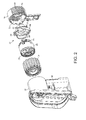
Figure 2 is an exploded view of the motor housing of the hand-held vacuum cleaner shown inFigure 1 , -
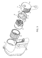
Figure 3 is an exploded view of the motor housing of the hand-held vacuum cleaner shown inFigure 1 , -
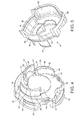
Figure 4 and Figure 5 are perspective views of an exhaust baffle having a plurality of blades projecting from the downstream face of the body in accordance with the second aspect of the present invention, -
Figure 6a is a side view of the motor housing of the hand held vacuum cleaner shown inFigure 1 , -
Figure 6b is a section through line B-B shown inFigure 6a , -
Figure 7a is a rear view of casing of the hand held vacuum cleaner shown inFigure 1 , -
Figure 7b is a section through line A-A shown inFigure 7a , -
Figure 7c is a close up view of the circled area shown inFigure 7b , -
Figure 8 and Figure 9 are perspective views of an alternative embodiment of an exhaust baffle having a plurality of blades projecting from the upstream face of the body in accordance with the second aspect of the present invention, and -
Figure 10 and Figure 11 are perspective views of an alternative embodiment of an exhaust baffle having a plurality of blades projecting from the upstream and the downstream face of the body in accordance with the second aspect of the present invention. -
Figure 1 shows a hand-heldvacuum cleaner 1. The hand-heldvacuum cleaner 1 comprises asuction conduit 2 having asuction opening 4. Thevacuum cleaner 1 also includescyclonic separating apparatus 6 for separating dirt and dust from an airflow drawn in through thesuction opening 4. Thecyclonic separating apparatus 6 is in communication with thesuction conduit 2 and thesuction opening 4. Thecyclonic separating apparatus 6 comprises anupstream cyclone 8 and a plurality ofdownstream cyclones 10. - The
vacuum cleaner 1 further includes amotor housing 12 and aremovable casing 14 having a plurality of exhaust vents 16 formed therein. An air flow path extends from thesuction opening 4, through thesuction conduit 2, thecyclonic separating apparatus 6 and themotor housing 12 to the exhaust vents 16. Ahandgrip 18 is located below themotor housing 12 for manipulating the hand-heldvacuum cleaner 1 when in use. Thehandgrip 18 is arranged so that thecyclonic separating apparatus 6 is located between thehandgrip 18 and thesuction opening 4. Thehandgrip 18 includes atrigger switch 20 which is positioned on the side of thehandgrip 18 closest to thesuction opening 4 such that thetrigger switch 20 can be manipulated by a user's index finger. Apower source 22 in the form of a lithium ion battery pack is connected to thehandgrip 18 through a mountingportion 24. - In
Figures 2 and3 it can be seen that anairflow generator 26 is located in themotor housing 12. In this embodiment, theairflow generator 26 takes the form of a brushless DC motor and fan assembly. Theairflow generator 26 has aninlet 28 and anoutlet 30. Theinlet 28 andoutlet 30 can be seen more clearly in the airflow diagram shown inFigure 7 . A pre-motor filter (not shown) may be located upstream of theinlet 28 for filtering fine particulates from the airflow. Anexhaust baffle 32 is located downstream of theoutlet 30. The pre-motor filter if present and theexhaust baffle 32 are located in the air path through thevacuum cleaner 1. - A
mount 34 may also be provided to support theairflow generator 26 inside themotor housing 12. Themount 34 may be formed from any suitable material but is preferably made from a soft material such as rubber, which provides cushioning between theairflow generator 26 and themotor housing 12. This advantageously helps to reduce the overall sound emitted by thevacuum cleaner 1 during use. - When operating, the
airflow generator 26 draws a flow of dirt- and dust-laden air into thesuction opening 4, through thesuction conduit 2 and into thecyclonic separating apparatus 6. The cleaned air exits thecyclonic separating apparatus 6 and passes sequentially through a pre-motor filter if present, theairflow generator 26 and theexhaust baffle 32 before being exhausted through the exhaust vents 16. - The
exhaust baffle 32 can be seen in more detail inFigures 4 and 5 . Theexhaust baffle 32 comprises a substantiallyplanar body 36 having anupstream face 38 and adownstream face 40, anairflow path 42 between the upstream and downstream faces 38, 40 and a plurality ofblades 44 projecting from thedownstream face 40, eachblade 44 having afirst side edge 46, asecond side edge 48 and aforward edge 50. - In the embodiments shown in the Figures the
exhaust baffle 32 is arranged downstream of theairflow generator 26 and upstream of the exhaust vents 16. Theexhaust baffle 32 is also physically located between theairflow generator 26 and the exhaust vents 16. In the embodiment shown inFigure 6b it can be seen that at least one of theblades 44 blocks the line of sight between theairflow generator 26 and at least one of the exhaust vents 16 such that the air has to follow a curved path as it moves past theblades 44 towards the exhaust vents 16. The exiting air can be seen by the arrows numbered 51. In the particular embodiment shown inFigure 6b the exhaust vents 16 are louvered. This provides a further lengthening of the air path through thevacuum cleaner 1 and further helps to stop the line of sight between theairflow generator 26 and the exhaust vents 16. - The
exhaust baffle 32 is removably located within thecasing 14. In the embodiment shown in the Figures thecasing 14 is substantially cup shaped, having aperimeter wall 52 and an end face 54 (SeeFigure 3 for the best view). In the embodiment shown the exhaust vents 16 are regularly spaced around thewall 52, although there are some areas of thewall 52 which are vent free. - Snap fit engagement means are provided between the
exhaust baffle 32 and thecasing 14. A pair ofprotrusions 56 are provided on theexhaust baffle 32 and a corresponding pair of protrusion accepting notches 58 (seeFigure 2 ) are present on an inner surface of thecasing 14. - In
Figures 2 to 7c , in order to ensure that substantially and preferably all of the air passing through theairflow path 42 flows past theblades 44 rather than over them an interface fit is provided between theforward edges 50 of theblades 44 and aninner surface 60 of theend face 54 of thecasing 14. In the arrangement shown inFigures 7a to 7c this is achieved by having agroove 62, for example a V-shapedgroove 62 on the forward edges 50 of theblades 44. Theinner surface 60 of theend face 54 of thecasing 14 has correspondingprojections 64 which are shaped to fit into thegrooves 62 on the forward edges 50 of theblades 44 to provide the interface fit. - A
skirt 66 extends from an outer edge of theupstream face 38 of theplanar body 36. Theskirt 66 is arranged to engage with thecasing 14 to provide a substantially airtight seal, such that during use substantially all or all of the airflow exhausting from theairflow generator 26 flows through theairflow path 42 towards the exhaust vents 16. - In the embodiments shown in
Figures 2 ,3 ,4, 5 and8 to 11 it can be seen that theprotrusion 56 of the snap-fit engagement means is located on an outer surface of theskirt 66. - As can be seen in
Figure 6b the first side edges 46 of theblades 44 are located at theedge 68 of theairflow path 42 and the second side edges 48 of theblades 44 are located near the exhaust vents 16. It can be seen that eachblade 44 is curved along its length towards the exhaust vents 16. In this embodiment theblades 44 project from thedownstream surface 40 of theplanar body 36. Theblades 44 thus form a plurality of passageways which curve away from theairflow passage 42 directing air towards the exhaust vents 16. Theblades 44 decrease in thickness along their length from their first side edges 46 to their second side edges 48. - In the embodiments shown in
Figures 2 to 7 theplaner body 36 is substantially circular in shape with theblades 44 arranged around circumferentially about itsdownstream face 40. Of course thebody 36 could be of any other suitable shape which would allow theblades 44 to be located on it. In these Figures it can be seen that the first 46 and second 48 side edges ofadjacent blades 44 overlap, the overlappingedges planar body 36. This allows air to pass between theblades 44 towards the exhaust vents 16 but blocks the line of sight between theairflow generator 26 and the exhaust vents 16. In the embodiment shown there are threeblades 44. It is of course possible to have more or less than this. It is preferred that thefirst side edge 46 of each blade starts in line with thesecond side edge 48 of theadjacent blade 44. In this way the line of sight between theairflow generator 42 and the exhaust vents 16 is always blocked. Thefirst side edge 46 of each blade can start before thesecond side edge 48 of theadjacent blade 44 such that they overlap. The distance between theblades 44 can vary although it is important that they do not provide too much of a restriction in terms of airflow through thevacuum cleaner 1. - In
Figure 6b it can be seen that the second side edges 48 of theblades 44 stop short of the outer edge of thebody 36. It is possible to have the second side edges 48 extending right up to the outer edge but this is only desirable in embodiments where there is at least oneexhaust vent 16 between suchadjacent blades 44 otherwise the air path would be blocked for any air that traveled betweensuch blades 44. - The
edge 68 of theairflow path 42 can be seen inFigure 6b . The size of the aperture is not critical although it is desirable for it to be larger than the size of thesuction opening 4 of thevacuum cleaner 1 to prevent back pressure from building up. In a preferred embodiment theedge 68 of the airflow path is 1.5 times the size of thesuction opening 4. -
Figure 8 and 9 show perspective views of an alternative embodiment of anexhaust baffle 32 having a plurality ofblades 44 projecting from theupstream face 38 of theplanar body 36.Figures 10 and 11 show perspective views of an alternative embodiment of anexhaust baffle 32 having a plurality ofblades 44 projecting from the upstream 36 and thedownstream face 38 of theplanar body 36. - In such embodiments it is also desirable that that there is an interface fit is provided between the
forward edges 50 of theblades 44 and aninner surface 60 of theend face 54 of thecasing 14, or with theairflow generator 26 or thehousing 12 of theairflow generator 26. Again this may be achieved by having agroove 62, for example a V-shapedgroove 62 on the forward edges 50 of theblades 44 and a corresponding projection on the appropriate part of the vacuum cleaner. - In embodiments which have
blades 44 located on bothfaces planar body 36, or on theupstream face 38 only, other features may be as described in relation to the first embodiment. - Ideally the
exhaust baffle 32 is designed to be as aerodynamic as possible. In order to achieve this, the surfaces are as smooth as possible. - The invention is defined by the claims and is not limited to the features of the specific embodiment described above.
- Variations of the specific embodiment will be apparent to the person skilled in the art.
Claims (14)
- A cleaning appliance (1) comprising an airflow generator (26) for generating an airflow, separating apparatus (6) for separating dirt and dust from the airflow, a power source (22) for supplying power to the airflow generator (26), wherein at least one exhaust vent (16) is located on a removable casing (14) of the cleaning appliance and an exhaust baffle (32) is removably located at least partially within the casing (14), characterized in that the exhaust baffle comprises a substantially planar body (36) having an upstream face (38) and a downstream face (40), an airflow path (42) between the upstream and downstream faces (38, 40) and a plurality of blades (44) projecting from the body, each blade (44) having a first side edge (46), a second side edge (48) and a forward edge (50), and further comprising a skirt (66) extending from an outer edge of the body (36), so as to engage the airflow generator (26), the casing (14) or a housing (12) of the airflow generator to provide an airtight or substantially airtight seal, such that during use, all or substantially all of the airflow exhausting from the airflow generator (26) flows through the airflow path towards the exhaust vent (16).
- A cleaning appliance according to claim 1 wherein the exhaust baffle (32) is arranged downstream of the airflow generator (26) and upstream of the exhaust vent(s) (16).
- A cleaning appliance according to claim 1 or 2 wherein the exhaust baffle (32) is physically located between the airflow generator (26) and the exhaust vent(s) (16).
- A cleaning appliance according to any of claims 1 to 3 wherein at least one of the blades (44) blocks the line of sight between the airflow generator (26) and at least one exhaust vent (16).
- A cleaning appliance according to any of claims 1 to 4 wherein there is an interface fit between the forward edges (50) of the blades (44) and an inner surface (60) of the casing (14).
- A cleaning appliance according to any preceding claim wherein the blades (44) project from the downstream face (40) of the body (36).
- An exhaust baffle (32) for a cleaning appliance comprising, a substantially planar body (36) having an upstream face (38) and a downstream face (40), an airflow path (42) between the upstream and downstream faces (38, 40), and a plurality of blades (44) projecting from the upstream or downstream face of the body (36), each blade (44) having a first side edge (46), a second side edge (48) and a forward edge (50), wherein the airflow path (42) is an aperture (42) formed through the body (36), from the upstream face (38) to the downstream face (40), characterized in that the first side edge (46) of each blade (44) is located near or at an edge of the aperture (42) and the second side edge (48) of each blade (44) is located at or near an outer edge of the body (36), and each blade (44) is curved along its length such that it spirals outwardly towards the outer edge of the body (36).
- An exhaust baffle according to claim 7 further comprising at least one engagement means for allowing engagement with a cleaning appliance or a component thereof.
- An exhaust baffle according to claim 8 wherein an engagement means comprises a skirt (66) extending from an outer edge of the upstream face (38) of the body (36).
- An exhaust baffle according to any of claims 7 to 9 wherein the forward edge (50) of at least one of the blades (44) is shaped to engage with a cleaning appliance or a component thereof.
- An exhaust baffle according to any of claims 7 to 10 wherein at least one blade (44) decreases in thickness along its length from its first side edge (46) to its second side edge (48) and/or at least one blade (44) is curved along its length.
- An exhaust baffle according to any of claims 7 to 11 wherein the planar body (36) is circular or substantially circular in shape.
- An exhaust baffle according to claim 12 wherein the blades (44) are arranged circumferentially around the planar body (36).
- An exhaust baffle according to claim 13 wherein the first and second side edges (46, 48) of adjacent blades overlap and/or wherein the first and second overlapping side edges are spaced along a radius of the planar body.
Applications Claiming Priority (2)
| Application Number | Priority Date | Filing Date | Title |
|---|---|---|---|
| GB0903587.4A GB2468299B (en) | 2009-03-03 | 2009-03-03 | Noise reduction arrangement for a cleaning appliance. |
| PCT/GB2010/050258 WO2010100447A1 (en) | 2009-03-03 | 2010-02-16 | Cleaning appliance |
Publications (2)
| Publication Number | Publication Date |
|---|---|
| EP2403390A1 EP2403390A1 (en) | 2012-01-11 |
| EP2403390B1 true EP2403390B1 (en) | 2015-05-27 |
Family
ID=40566030
Family Applications (1)
| Application Number | Title | Priority Date | Filing Date |
|---|---|---|---|
| EP10705410.8A Not-in-force EP2403390B1 (en) | 2009-03-03 | 2010-02-16 | Cleaning appliance |
Country Status (6)
| Country | Link |
|---|---|
| US (1) | US8397344B2 (en) |
| EP (1) | EP2403390B1 (en) |
| JP (1) | JP4920091B2 (en) |
| CN (1) | CN101822505B (en) |
| GB (1) | GB2468299B (en) |
| WO (1) | WO2010100447A1 (en) |
Families Citing this family (51)
| Publication number | Priority date | Publication date | Assignee | Title |
|---|---|---|---|---|
| EP2581018B1 (en) | 2011-10-12 | 2019-06-26 | Black & Decker Inc. | Cyclonic separation apparatus |
| DE102012100046A1 (en) * | 2012-01-04 | 2013-07-04 | Miele & Cie. Kg | Vacuum cleaner and method for operating a vacuum cleaner |
| GB2499240B (en) * | 2012-02-10 | 2014-08-20 | Dyson Technology Ltd | Vacuum cleaner |
| GB2506436B (en) * | 2012-10-01 | 2014-08-20 | Dyson Technology Ltd | Cyclonic separator |
| GB2506654B (en) * | 2012-10-05 | 2017-05-03 | Dyson Technology Ltd | Vibration isolation mount for an electric motor |
| US9259126B2 (en) | 2012-10-10 | 2016-02-16 | Electrolux Home Care Products, Inc. | Backpack vacuum cleaner |
| USD696479S1 (en) | 2012-10-12 | 2013-12-24 | Electrolux Home Care Products, Inc. | Backpack vacuum cleaner |
| GB2513661B (en) * | 2013-05-03 | 2016-03-16 | Dyson Technology Ltd | Vibration isolation mount |
| GB2513662B (en) * | 2013-05-03 | 2015-10-21 | Dyson Technology Ltd | Compressor flow path |
| GB2531563B (en) * | 2014-10-22 | 2017-04-05 | Dyson Technology Ltd | Vacuum cleaner with motor cooling |
| GB2531561B (en) | 2014-10-22 | 2018-03-21 | Dyson Technology Ltd | Vacuum cleaner with motor between separation stages |
| KR101509738B1 (en) * | 2014-10-27 | 2015-04-14 | 주식회사코네트인더스트리 | Dust-container assembly of vacuum cleaner |
| GB2542388B (en) * | 2015-09-17 | 2018-04-04 | Dyson Technology Ltd | Vacuum cleaner |
| GB2542387B (en) * | 2015-09-17 | 2017-11-01 | Dyson Technology Ltd | Vacuum cleaner |
| EP3393322B1 (en) * | 2015-12-21 | 2020-04-08 | Alfred Kärcher SE & Co. KG | Portable hard surface cleaning device |
| US10080471B2 (en) | 2015-12-21 | 2018-09-25 | Electrolux Home Care Products, Inc. | Versatile vacuum cleaners |
| FR3046046B1 (en) * | 2015-12-23 | 2017-12-22 | Seb Sa | GEOMETRY OF AERAULIC CIRCUIT FOR A HAND VACUUM |
| KR102560970B1 (en) | 2016-03-31 | 2023-07-31 | 엘지전자 주식회사 | Cleaner |
| US11166607B2 (en) | 2016-03-31 | 2021-11-09 | Lg Electronics Inc. | Cleaner |
| EP3437533B1 (en) | 2016-03-31 | 2024-07-03 | LG Electronics Inc. | Cleaning apparatus |
| USD813475S1 (en) | 2016-06-01 | 2018-03-20 | Milwaukee Electric Tool Corporation | Handheld vacuum cleaner |
| FR3055070B1 (en) * | 2016-08-11 | 2018-09-07 | Alstom Transport Technologies | ELECTRIC MOTOR COMPRISING A DEVICE OF HIGH ACOUSTICAL ATTENUATION |
| FR3055071B1 (en) * | 2016-08-11 | 2018-09-07 | Alstom Transport Technologies | ELECTRIC MOTOR COMPRISING AN ACOUSTICAL ATTENUATION DEVICE |
| US10448797B2 (en) | 2016-10-19 | 2019-10-22 | Tti (Macao Commercial Offshore) Limited | Vacuum cleaner |
| JP2018117505A (en) * | 2017-01-20 | 2018-07-26 | 日本電産株式会社 | Motor and blower including the same |
| WO2018152844A1 (en) * | 2017-02-27 | 2018-08-30 | Tti (Macao Commercial Offshore) Limited | Handheld vacuum cleaner |
| AU201715476S (en) | 2017-03-16 | 2017-10-09 | Dyson Technology Ltd | Vacuum cleaner |
| AU201715444S (en) | 2017-03-16 | 2017-10-10 | Dyson Technology Ltd | Vacuum cleaner |
| AU201715412S (en) | 2017-03-16 | 2017-10-09 | Dyson Technology Ltd | Vacuum cleaner |
| AU201715439S (en) | 2017-03-16 | 2017-10-10 | Dyson Technology Ltd | Vacuum cleaner |
| AU201715432S (en) | 2017-03-16 | 2017-10-10 | Dyson Technology Ltd | Vacuum cleaner |
| AU201715425S (en) | 2017-03-16 | 2017-10-09 | Dyson Technology Ltd | Vacuum cleaner |
| AU201715409S (en) | 2017-03-16 | 2017-10-04 | Dyson Technology Ltd | Vacuum cleaner |
| AU201715474S (en) | 2017-03-16 | 2017-10-09 | Dyson Technology Ltd | Vacuum cleaner |
| CN108903781A (en) * | 2018-08-29 | 2018-11-30 | 珠海格力电器股份有限公司 | Hand-held type dust catcher |
| GB2578873B (en) * | 2018-11-09 | 2021-08-18 | Dyson Technology Ltd | A vacuum cleaner and a filter assembly |
| USD977770S1 (en) * | 2019-06-14 | 2023-02-07 | Sharkninja Operating Llc | Hand vacuum |
| CN114040698A (en) * | 2019-07-08 | 2022-02-11 | 伊莱克斯公司 | Hand-held vacuum cleaner and vacuum cleaner comprising a hand-held vacuum cleaner |
| CN112205921B (en) * | 2019-07-09 | 2021-11-12 | 江苏美的清洁电器股份有限公司 | Vacuum cleaner |
| AU2020205211B2 (en) | 2019-08-02 | 2026-01-15 | Techtronic Cordless Gp | Blowers having noise reduction features |
| WO2021056329A1 (en) * | 2019-09-26 | 2021-04-01 | 深圳市智意科技有限公司 | Cyclone filter device, and vacuuming apparatus |
| JP2021065463A (en) * | 2019-10-24 | 2021-04-30 | 株式会社マキタ | Dust collector |
| CN110664312A (en) * | 2019-11-13 | 2020-01-10 | 珠海格力电器股份有限公司 | Motor and dust catcher |
| USD943228S1 (en) * | 2020-01-17 | 2022-02-08 | Suzhou Pooda Clean Technology Co., Ltd. | Vacuum cleaner |
| CN214742186U (en) | 2020-01-21 | 2021-11-16 | 创科无线普通合伙 | Blower fan |
| AU2020286200A1 (en) | 2020-01-21 | 2021-08-05 | Techtronic Cordless Gp | Power tool having noise reduction features |
| FR3107173B1 (en) * | 2020-02-13 | 2022-03-11 | Seb Sa | Portable vacuum cleaner equipped with a main casing comprising a first and a second distinct casing parts |
| JP7514668B2 (en) * | 2020-06-29 | 2024-07-11 | 株式会社マキタ | Cleaner |
| DE102021109222A1 (en) | 2021-04-13 | 2022-10-13 | Alfred Kärcher SE & Co. KG | vacuum cleaner |
| WO2025247570A1 (en) * | 2024-05-30 | 2025-12-04 | Versuni Holding B.V. | Silencing assembly, silencing system, and cleaning device |
| EP4656108A1 (en) * | 2024-05-30 | 2025-12-03 | Versuni Holding B.V. | Silencing assembly, silencing system, and cleaning device |
Family Cites Families (18)
| Publication number | Priority date | Publication date | Assignee | Title |
|---|---|---|---|---|
| NL196603A (en) * | 1954-05-19 | |||
| FR1554851A (en) | 1967-12-08 | 1969-01-24 | ||
| DE1964475A1 (en) * | 1969-12-23 | 1971-07-01 | Licentia Gmbh | Hand vacuum cleaner |
| JPS5664761A (en) | 1979-06-26 | 1981-06-02 | Kyowa Shokuhin:Kk | Preparation of crab paste food |
| US4970753A (en) * | 1990-02-23 | 1990-11-20 | Ryobi Motor Products Corp. | Vacuum cleaner noise reducing arrangement |
| FI113892B (en) | 1998-09-30 | 2004-06-30 | Metso Paper Inc | Reactive silencer for industrial air ducts and its use |
| US20010052165A1 (en) * | 2000-04-19 | 2001-12-20 | Anderson Troy Gene | De-turbulent hand-held vacuum cleaner |
| EP1320318B1 (en) * | 2000-09-29 | 2012-10-24 | Oreck Holdings, LLC | Contoured intake ducts and fan housing assemblies for floor care machines |
| US6629818B2 (en) * | 2001-02-09 | 2003-10-07 | The Toro Company | Impeller for use with portable blower/vacuums |
| GB0203147D0 (en) * | 2002-02-11 | 2002-03-27 | Dyson Ltd | An exhaust assembly |
| DE10221443A1 (en) * | 2002-05-12 | 2003-12-04 | Kern Gmbh Dr. | Vacuum cleaner in built silencer, is housed together with blower and axially deflected by air from wheel with intake nozzle molded on blower intake face. |
| KR100474807B1 (en) * | 2002-11-06 | 2005-03-11 | 주식회사코네트인더스트리 | Vacuum cleaner |
| US7475449B2 (en) * | 2003-12-24 | 2009-01-13 | Daewoo Electronics Corporation | Vacuum cleaner |
| KR100676317B1 (en) * | 2005-05-18 | 2007-01-30 | 삼성광주전자 주식회사 | Vacuum cleaner |
| US7647670B2 (en) * | 2005-09-07 | 2010-01-19 | Panasonic Corporation Of North America | Vacuum cleaner with final filtration compartment for reducing noise |
| KR100721305B1 (en) * | 2005-11-28 | 2007-05-28 | 삼성광주전자 주식회사 | Fan assembly for vacuum cleaner |
| GB2436787A (en) * | 2006-04-05 | 2007-10-10 | Vax Ltd | Electric motor housing |
| CN101204302A (en) | 2006-12-20 | 2008-06-25 | 乐金电子(天津)电器有限公司 | Motor impeller structure of dust collector |
-
2009
- 2009-03-03 GB GB0903587.4A patent/GB2468299B/en not_active Expired - Fee Related
-
2010
- 2010-02-16 EP EP10705410.8A patent/EP2403390B1/en not_active Not-in-force
- 2010-02-16 WO PCT/GB2010/050258 patent/WO2010100447A1/en not_active Ceased
- 2010-02-19 US US12/709,150 patent/US8397344B2/en not_active Expired - Fee Related
- 2010-02-25 JP JP2010039761A patent/JP4920091B2/en not_active Expired - Fee Related
- 2010-03-02 CN CN2010101235716A patent/CN101822505B/en not_active Expired - Fee Related
Also Published As
| Publication number | Publication date |
|---|---|
| JP4920091B2 (en) | 2012-04-18 |
| US8397344B2 (en) | 2013-03-19 |
| EP2403390A1 (en) | 2012-01-11 |
| CN101822505B (en) | 2013-10-16 |
| GB2468299B (en) | 2012-06-20 |
| JP2010201169A (en) | 2010-09-16 |
| US20100223751A1 (en) | 2010-09-09 |
| WO2010100447A1 (en) | 2010-09-10 |
| CN101822505A (en) | 2010-09-08 |
| GB0903587D0 (en) | 2009-04-08 |
| GB2468299A (en) | 2010-09-08 |
Similar Documents
| Publication | Publication Date | Title |
|---|---|---|
| US8397344B2 (en) | Cleaning appliance | |
| KR101821908B1 (en) | Electric vacuum cleaner | |
| CN104822301B (en) | Electric vacuum cleaner | |
| CA2553412A1 (en) | Hand-holdable vacuum cleaners | |
| JP7201070B2 (en) | Blower | |
| JP6291218B2 (en) | Electric vacuum cleaner | |
| CN101721172B (en) | Electric dust collector | |
| KR20070072915A (en) | Vacuum cleaner and its suction port | |
| JP6710513B2 (en) | Suction mouth and vacuum cleaner | |
| JP6500209B2 (en) | Dust collector | |
| CN211511630U (en) | Household dust collector | |
| CN217645111U (en) | Dirt cup subassembly and surface cleaning equipment | |
| CN110248582B (en) | Cyclone separation device | |
| JP3597041B2 (en) | Electric blower and vacuum cleaner | |
| JP2010022575A (en) | Vacuum cleaner | |
| CA2551866A1 (en) | Vacuum cleaner with final filtration compartment for reducing noise | |
| CN115956832B (en) | Inhalation body and electric vacuum cleaner | |
| CN107212809B (en) | trash can vacuum cleaner | |
| JP7663471B2 (en) | Suction port body and vacuum cleaner | |
| JP6599596B2 (en) | Electric vacuum cleaner | |
| CN211749282U (en) | Hand-held type cleaning device and part that induced drafts | |
| JP6552785B2 (en) | Electric vacuum cleaner | |
| JP2020000562A (en) | Suction port body of vacuum cleaner and vacuum cleaner with the suction port body | |
| JP2014138639A (en) | Vacuum cleaner | |
| HK1222777B (en) | Electric vacuum cleaner |
Legal Events
| Date | Code | Title | Description |
|---|---|---|---|
| PUAI | Public reference made under article 153(3) epc to a published international application that has entered the european phase |
Free format text: ORIGINAL CODE: 0009012 |
|
| 17P | Request for examination filed |
Effective date: 20110905 |
|
| AK | Designated contracting states |
Kind code of ref document: A1 Designated state(s): AT BE BG CH CY CZ DE DK EE ES FI FR GB GR HR HU IE IS IT LI LT LU LV MC MK MT NL NO PL PT RO SE SI SK SM TR |
|
| DAX | Request for extension of the european patent (deleted) | ||
| 17Q | First examination report despatched |
Effective date: 20140613 |
|
| GRAP | Despatch of communication of intention to grant a patent |
Free format text: ORIGINAL CODE: EPIDOSNIGR1 |
|
| INTG | Intention to grant announced |
Effective date: 20150303 |
|
| RBV | Designated contracting states (corrected) |
Designated state(s): AT BE BG CH CY CZ DE DK EE ES FI FR GR HR HU IE IS IT LI LT LU LV MC MK MT NL NO PL PT RO SE SI SK SM TR |
|
| GRAS | Grant fee paid |
Free format text: ORIGINAL CODE: EPIDOSNIGR3 |
|
| GRAA | (expected) grant |
Free format text: ORIGINAL CODE: 0009210 |
|
| AK | Designated contracting states |
Kind code of ref document: B1 Designated state(s): AT BE BG CH CY CZ DE DK EE ES FI FR GR HR HU IE IS IT LI LT LU LV MC MK MT NL NO PL PT RO SE SI SK SM TR |
|
| REG | Reference to a national code |
Ref country code: CH Ref legal event code: EP |
|
| REG | Reference to a national code |
Ref country code: AT Ref legal event code: REF Ref document number: 728383 Country of ref document: AT Kind code of ref document: T Effective date: 20150615 |
|
| REG | Reference to a national code |
Ref country code: IE Ref legal event code: FG4D |
|
| REG | Reference to a national code |
Ref country code: DE Ref legal event code: R096 Ref document number: 602010024888 Country of ref document: DE |
|
| REG | Reference to a national code |
Ref country code: AT Ref legal event code: MK05 Ref document number: 728383 Country of ref document: AT Kind code of ref document: T Effective date: 20150527 |
|
| REG | Reference to a national code |
Ref country code: LT Ref legal event code: MG4D |
|
| PG25 | Lapsed in a contracting state [announced via postgrant information from national office to epo] |
Ref country code: NO Free format text: LAPSE BECAUSE OF FAILURE TO SUBMIT A TRANSLATION OF THE DESCRIPTION OR TO PAY THE FEE WITHIN THE PRESCRIBED TIME-LIMIT Effective date: 20150827 Ref country code: ES Free format text: LAPSE BECAUSE OF FAILURE TO SUBMIT A TRANSLATION OF THE DESCRIPTION OR TO PAY THE FEE WITHIN THE PRESCRIBED TIME-LIMIT Effective date: 20150527 Ref country code: LT Free format text: LAPSE BECAUSE OF FAILURE TO SUBMIT A TRANSLATION OF THE DESCRIPTION OR TO PAY THE FEE WITHIN THE PRESCRIBED TIME-LIMIT Effective date: 20150527 Ref country code: PT Free format text: LAPSE BECAUSE OF FAILURE TO SUBMIT A TRANSLATION OF THE DESCRIPTION OR TO PAY THE FEE WITHIN THE PRESCRIBED TIME-LIMIT Effective date: 20150928 Ref country code: FI Free format text: LAPSE BECAUSE OF FAILURE TO SUBMIT A TRANSLATION OF THE DESCRIPTION OR TO PAY THE FEE WITHIN THE PRESCRIBED TIME-LIMIT Effective date: 20150527 Ref country code: HR Free format text: LAPSE BECAUSE OF FAILURE TO SUBMIT A TRANSLATION OF THE DESCRIPTION OR TO PAY THE FEE WITHIN THE PRESCRIBED TIME-LIMIT Effective date: 20150527 |
|
| REG | Reference to a national code |
Ref country code: NL Ref legal event code: MP Effective date: 20150527 |
|
| PG25 | Lapsed in a contracting state [announced via postgrant information from national office to epo] |
Ref country code: GR Free format text: LAPSE BECAUSE OF FAILURE TO SUBMIT A TRANSLATION OF THE DESCRIPTION OR TO PAY THE FEE WITHIN THE PRESCRIBED TIME-LIMIT Effective date: 20150828 Ref country code: BG Free format text: LAPSE BECAUSE OF FAILURE TO SUBMIT A TRANSLATION OF THE DESCRIPTION OR TO PAY THE FEE WITHIN THE PRESCRIBED TIME-LIMIT Effective date: 20150827 Ref country code: LV Free format text: LAPSE BECAUSE OF FAILURE TO SUBMIT A TRANSLATION OF THE DESCRIPTION OR TO PAY THE FEE WITHIN THE PRESCRIBED TIME-LIMIT Effective date: 20150527 Ref country code: AT Free format text: LAPSE BECAUSE OF FAILURE TO SUBMIT A TRANSLATION OF THE DESCRIPTION OR TO PAY THE FEE WITHIN THE PRESCRIBED TIME-LIMIT Effective date: 20150527 Ref country code: IS Free format text: LAPSE BECAUSE OF FAILURE TO SUBMIT A TRANSLATION OF THE DESCRIPTION OR TO PAY THE FEE WITHIN THE PRESCRIBED TIME-LIMIT Effective date: 20150927 |
|
| PG25 | Lapsed in a contracting state [announced via postgrant information from national office to epo] |
Ref country code: EE Free format text: LAPSE BECAUSE OF FAILURE TO SUBMIT A TRANSLATION OF THE DESCRIPTION OR TO PAY THE FEE WITHIN THE PRESCRIBED TIME-LIMIT Effective date: 20150527 Ref country code: DK Free format text: LAPSE BECAUSE OF FAILURE TO SUBMIT A TRANSLATION OF THE DESCRIPTION OR TO PAY THE FEE WITHIN THE PRESCRIBED TIME-LIMIT Effective date: 20150527 |
|
| PG25 | Lapsed in a contracting state [announced via postgrant information from national office to epo] |
Ref country code: RO Free format text: LAPSE BECAUSE OF NON-PAYMENT OF DUE FEES Effective date: 20150527 Ref country code: PL Free format text: LAPSE BECAUSE OF FAILURE TO SUBMIT A TRANSLATION OF THE DESCRIPTION OR TO PAY THE FEE WITHIN THE PRESCRIBED TIME-LIMIT Effective date: 20150527 Ref country code: SK Free format text: LAPSE BECAUSE OF FAILURE TO SUBMIT A TRANSLATION OF THE DESCRIPTION OR TO PAY THE FEE WITHIN THE PRESCRIBED TIME-LIMIT Effective date: 20150527 Ref country code: CZ Free format text: LAPSE BECAUSE OF FAILURE TO SUBMIT A TRANSLATION OF THE DESCRIPTION OR TO PAY THE FEE WITHIN THE PRESCRIBED TIME-LIMIT Effective date: 20150527 |
|
| REG | Reference to a national code |
Ref country code: DE Ref legal event code: R097 Ref document number: 602010024888 Country of ref document: DE |
|
| PLBE | No opposition filed within time limit |
Free format text: ORIGINAL CODE: 0009261 |
|
| STAA | Information on the status of an ep patent application or granted ep patent |
Free format text: STATUS: NO OPPOSITION FILED WITHIN TIME LIMIT |
|
| PG25 | Lapsed in a contracting state [announced via postgrant information from national office to epo] |
Ref country code: IT Free format text: LAPSE BECAUSE OF FAILURE TO SUBMIT A TRANSLATION OF THE DESCRIPTION OR TO PAY THE FEE WITHIN THE PRESCRIBED TIME-LIMIT Effective date: 20150527 |
|
| 26N | No opposition filed |
Effective date: 20160301 |
|
| PG25 | Lapsed in a contracting state [announced via postgrant information from national office to epo] |
Ref country code: SI Free format text: LAPSE BECAUSE OF FAILURE TO SUBMIT A TRANSLATION OF THE DESCRIPTION OR TO PAY THE FEE WITHIN THE PRESCRIBED TIME-LIMIT Effective date: 20150527 Ref country code: BE Free format text: LAPSE BECAUSE OF NON-PAYMENT OF DUE FEES Effective date: 20160229 |
|
| PG25 | Lapsed in a contracting state [announced via postgrant information from national office to epo] |
Ref country code: BE Free format text: LAPSE BECAUSE OF FAILURE TO SUBMIT A TRANSLATION OF THE DESCRIPTION OR TO PAY THE FEE WITHIN THE PRESCRIBED TIME-LIMIT Effective date: 20150527 |
|
| PG25 | Lapsed in a contracting state [announced via postgrant information from national office to epo] |
Ref country code: MC Free format text: LAPSE BECAUSE OF FAILURE TO SUBMIT A TRANSLATION OF THE DESCRIPTION OR TO PAY THE FEE WITHIN THE PRESCRIBED TIME-LIMIT Effective date: 20150527 Ref country code: LU Free format text: LAPSE BECAUSE OF FAILURE TO SUBMIT A TRANSLATION OF THE DESCRIPTION OR TO PAY THE FEE WITHIN THE PRESCRIBED TIME-LIMIT Effective date: 20160216 |
|
| REG | Reference to a national code |
Ref country code: CH Ref legal event code: PL |
|
| PG25 | Lapsed in a contracting state [announced via postgrant information from national office to epo] |
Ref country code: LI Free format text: LAPSE BECAUSE OF NON-PAYMENT OF DUE FEES Effective date: 20160229 Ref country code: CH Free format text: LAPSE BECAUSE OF NON-PAYMENT OF DUE FEES Effective date: 20160229 |
|
| REG | Reference to a national code |
Ref country code: FR Ref legal event code: ST Effective date: 20161028 |
|
| REG | Reference to a national code |
Ref country code: IE Ref legal event code: MM4A |
|
| PG25 | Lapsed in a contracting state [announced via postgrant information from national office to epo] |
Ref country code: FR Free format text: LAPSE BECAUSE OF NON-PAYMENT OF DUE FEES Effective date: 20160229 Ref country code: IE Free format text: LAPSE BECAUSE OF NON-PAYMENT OF DUE FEES Effective date: 20160216 |
|
| PG25 | Lapsed in a contracting state [announced via postgrant information from national office to epo] |
Ref country code: SE Free format text: LAPSE BECAUSE OF FAILURE TO SUBMIT A TRANSLATION OF THE DESCRIPTION OR TO PAY THE FEE WITHIN THE PRESCRIBED TIME-LIMIT Effective date: 20150527 Ref country code: NL Free format text: LAPSE BECAUSE OF FAILURE TO SUBMIT A TRANSLATION OF THE DESCRIPTION OR TO PAY THE FEE WITHIN THE PRESCRIBED TIME-LIMIT Effective date: 20150527 |
|
| PG25 | Lapsed in a contracting state [announced via postgrant information from national office to epo] |
Ref country code: MT Free format text: LAPSE BECAUSE OF FAILURE TO SUBMIT A TRANSLATION OF THE DESCRIPTION OR TO PAY THE FEE WITHIN THE PRESCRIBED TIME-LIMIT Effective date: 20150527 |
|
| PG25 | Lapsed in a contracting state [announced via postgrant information from national office to epo] |
Ref country code: SM Free format text: LAPSE BECAUSE OF FAILURE TO SUBMIT A TRANSLATION OF THE DESCRIPTION OR TO PAY THE FEE WITHIN THE PRESCRIBED TIME-LIMIT Effective date: 20150527 Ref country code: HU Free format text: LAPSE BECAUSE OF FAILURE TO SUBMIT A TRANSLATION OF THE DESCRIPTION OR TO PAY THE FEE WITHIN THE PRESCRIBED TIME-LIMIT; INVALID AB INITIO Effective date: 20100216 Ref country code: CY Free format text: LAPSE BECAUSE OF FAILURE TO SUBMIT A TRANSLATION OF THE DESCRIPTION OR TO PAY THE FEE WITHIN THE PRESCRIBED TIME-LIMIT Effective date: 20150527 |
|
| PG25 | Lapsed in a contracting state [announced via postgrant information from national office to epo] |
Ref country code: MT Free format text: LAPSE BECAUSE OF FAILURE TO SUBMIT A TRANSLATION OF THE DESCRIPTION OR TO PAY THE FEE WITHIN THE PRESCRIBED TIME-LIMIT Effective date: 20160229 Ref country code: MK Free format text: LAPSE BECAUSE OF FAILURE TO SUBMIT A TRANSLATION OF THE DESCRIPTION OR TO PAY THE FEE WITHIN THE PRESCRIBED TIME-LIMIT Effective date: 20150527 Ref country code: TR Free format text: LAPSE BECAUSE OF FAILURE TO SUBMIT A TRANSLATION OF THE DESCRIPTION OR TO PAY THE FEE WITHIN THE PRESCRIBED TIME-LIMIT Effective date: 20150527 |
|
| PGFP | Annual fee paid to national office [announced via postgrant information from national office to epo] |
Ref country code: DE Payment date: 20190227 Year of fee payment: 10 |
|
| REG | Reference to a national code |
Ref country code: DE Ref legal event code: R119 Ref document number: 602010024888 Country of ref document: DE |
|
| PG25 | Lapsed in a contracting state [announced via postgrant information from national office to epo] |
Ref country code: DE Free format text: LAPSE BECAUSE OF NON-PAYMENT OF DUE FEES Effective date: 20200901 |