EP2403155A1 - Method and transmitter for implementing dirty paper pre-coding by using phase shaping anew - Google Patents
Method and transmitter for implementing dirty paper pre-coding by using phase shaping anew Download PDFInfo
- Publication number
- EP2403155A1 EP2403155A1 EP09840616A EP09840616A EP2403155A1 EP 2403155 A1 EP2403155 A1 EP 2403155A1 EP 09840616 A EP09840616 A EP 09840616A EP 09840616 A EP09840616 A EP 09840616A EP 2403155 A1 EP2403155 A1 EP 2403155A1
- Authority
- EP
- European Patent Office
- Prior art keywords
- constellation
- signal
- block
- size
- extended
- Prior art date
- Legal status (The legal status is an assumption and is not a legal conclusion. Google has not performed a legal analysis and makes no representation as to the accuracy of the status listed.)
- Ceased
Links
Images


Classifications
-
- H—ELECTRICITY
- H04—ELECTRIC COMMUNICATION TECHNIQUE
- H04L—TRANSMISSION OF DIGITAL INFORMATION, e.g. TELEGRAPHIC COMMUNICATION
- H04L27/00—Modulated-carrier systems
- H04L27/32—Carrier systems characterised by combinations of two or more of the types covered by groups H04L27/02, H04L27/10, H04L27/18 or H04L27/26
- H04L27/34—Amplitude- and phase-modulated carrier systems, e.g. quadrature-amplitude modulated carrier systems
- H04L27/3488—Multiresolution systems
-
- H—ELECTRICITY
- H03—ELECTRONIC CIRCUITRY
- H03M—CODING; DECODING; CODE CONVERSION IN GENERAL
- H03M13/00—Coding, decoding or code conversion, for error detection or error correction; Coding theory basic assumptions; Coding bounds; Error probability evaluation methods; Channel models; Simulation or testing of codes
-
- H—ELECTRICITY
- H04—ELECTRIC COMMUNICATION TECHNIQUE
- H04L—TRANSMISSION OF DIGITAL INFORMATION, e.g. TELEGRAPHIC COMMUNICATION
- H04L1/00—Arrangements for detecting or preventing errors in the information received
- H04L1/004—Arrangements for detecting or preventing errors in the information received by using forward error control
- H04L1/0041—Arrangements at the transmitter end
- H04L1/0042—Encoding specially adapted to other signal generation operation, e.g. in order to reduce transmit distortions, jitter, or to improve signal shape
-
- H—ELECTRICITY
- H04—ELECTRIC COMMUNICATION TECHNIQUE
- H04L—TRANSMISSION OF DIGITAL INFORMATION, e.g. TELEGRAPHIC COMMUNICATION
- H04L25/00—Baseband systems
- H04L25/38—Synchronous or start-stop systems, e.g. for Baudot code
- H04L25/40—Transmitting circuits; Receiving circuits
- H04L25/49—Transmitting circuits; Receiving circuits using code conversion at the transmitter; using predistortion; using insertion of idle bits for obtaining a desired frequency spectrum; using three or more amplitude levels ; Baseband coding techniques specific to data transmission systems
- H04L25/497—Transmitting circuits; Receiving circuits using code conversion at the transmitter; using predistortion; using insertion of idle bits for obtaining a desired frequency spectrum; using three or more amplitude levels ; Baseband coding techniques specific to data transmission systems by correlative coding, e.g. partial response coding or echo modulation coding transmitters and receivers for partial response systems
-
- H—ELECTRICITY
- H04—ELECTRIC COMMUNICATION TECHNIQUE
- H04L—TRANSMISSION OF DIGITAL INFORMATION, e.g. TELEGRAPHIC COMMUNICATION
- H04L25/00—Baseband systems
- H04L25/38—Synchronous or start-stop systems, e.g. for Baudot code
- H04L25/40—Transmitting circuits; Receiving circuits
- H04L25/49—Transmitting circuits; Receiving circuits using code conversion at the transmitter; using predistortion; using insertion of idle bits for obtaining a desired frequency spectrum; using three or more amplitude levels ; Baseband coding techniques specific to data transmission systems
- H04L25/497—Transmitting circuits; Receiving circuits using code conversion at the transmitter; using predistortion; using insertion of idle bits for obtaining a desired frequency spectrum; using three or more amplitude levels ; Baseband coding techniques specific to data transmission systems by correlative coding, e.g. partial response coding or echo modulation coding transmitters and receivers for partial response systems
- H04L25/4975—Correlative coding using Tomlinson precoding, Harashima precoding, Trellis precoding or GPRS
-
- H—ELECTRICITY
- H04—ELECTRIC COMMUNICATION TECHNIQUE
- H04L—TRANSMISSION OF DIGITAL INFORMATION, e.g. TELEGRAPHIC COMMUNICATION
- H04L27/00—Modulated-carrier systems
- H04L27/18—Phase-modulated carrier systems, i.e. using phase-shift keying
Definitions
- the present invention relates to communication field, especially to a dirty paper precoding method and transmitter implemented by using phase reshaping at the transmitter side.
- a good BER (bit error rate)-Eb/N0 performance can be achieved no matter whether the amplitude of interference signal is larger, smaller or equal to the intended signal.
- DPC Dirty Paper Coding
- THP Tomlinson-Harashima Precoding
- THP is attractive due to its simple implementation.
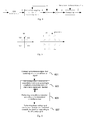
- Fig.1 illustrates the principle diagram of THP method with interference and additive Gaussian noise.
- intended signal v of the dirty paper precoding pre-subtracts interference signal s at the transmitter side and obtains difference signal d.
- the d modulo-M (an integer) signal is obtained via the quantization process by quantizer Q.
- Q what the transmitter sends is output signal of Q, also d modulo-M (an integer) instead of the difference signal d to make sure the output signal within the power constraint.
- intended signal can be reconstructed as v ⁇ , that is, the estimate signal of the intended signal after the receiving signal y is quantized by the same quantizer Q.
- v-s Operation (v-s) in Fig. 1 results in the constellation points as shown in Fig. 2(c) .
- Each constellation point shown in Fig. 2(c) has both information (comprising amplitude and phase information) of intended signal v and the interference signal s.
- modulo operation of the difference signal (v-s) will decrease the distance between different constellation points in the same quadrant.
- the possible constellation points of the received signal y are shown in Fig. 2d .
- the constellation of the received signal y is the enlarged constellation of signal v from QPSK to 16QAM.
- different constellation points with same shapes and different shadow fillings are isolated at different quadrants.
- phase reconstruction of intended signal v from the received signal y can hardly achieve.
- the case of QPSK is shown in Fig. 3 , which has the similar problem to Fig. 2 .
- Ref 3 is an improvement of THP method described in Refs 1 and 2, which is named as SDPC (Structural Dirty Paper Coding). This method discusses the improvement of THP method on the assumption that the receiver side has known the modulation structure of the interference signal.
- Fig. 4 illustrates the principle structure of SDPC, where the source signal u is performed by quadrature amplitude modulation. By precoding the modulated signal v, since the receiver side has known the modulation structure of the interference signal and the receiver has also prior knowledge of the constellation of the received signal y; therefore, SDPC has better demodulation performance than THP. However, the phase reconstruction problem is solved to some extend at the cost that the receiver knows the modulation structure of the interference signal. This problem is shown in Figure 5 . What's more, in case that source signal and interference signal are both QPSK, the receiver side has to perform 16QAM decoding on the received signal y whose constellation is enlarged to reconstruct the phase of source signal.
- the present invention is proposed in order to overcome the aforesaid drawbacks. Therefore, the purpose of the present invention is a dirty paper precoding method and transmitter implemented by using phase reshaping at the transmitter side. A good BER-Eb/N0 performance can be achieved no matter whether the amplitude of interference signal is larger, smaller or equal to the intended signal.
- a dirty paper precoding method implemented by using phase reshaping at the transmitter side comprising: subtracting interference signal from intended signal to obtain difference signal; determining constellation size for constellation extension according to amplitude-related information of interference signal and intended signal; extendedly mapping original constellation block of the difference signal to extended constellation block having the determined constellation size by constellation extension processing, according to the determined constellation size for constellation extension, the extended constellation block being proportionally enlarged to be closer to origin of constellation coordinate compared with original constellation block; and performing phase reshaping of each constellation point of extended constellation block corresponding to the difference signal, the phase reshaping making constellation point of extended constellation block of difference signal corresponding to specific constellation point of intended signal to be mapped into the same constellation quadrant as that of the specific constellation point.
- the amplitude-related information is amplitudes of intended signal and interference signal.
- the amplitude-related information is constellation block size of interference signal and constellation block size of intended signal.
- the intended signal is modulated signal.
- a transmitter for implementing dirty paper precoding method by using phase reshaping comprising: means for obtaining difference signal, for subtracting interference signal from intended signal to obtain difference signal; means for determining constellation size, for determining constellation size for constellation extension according to amplitude-related information of interference signal and intended signal; means for extended constellation mapping, for extendedly mapping original constellation block of the difference signal to extended constellation block having the determined constellation size by constellation extension processing, according to the determined constellation size for constellation extension, the extended constellation block being proportionally enlarged to be closer to origin of constellation coordinate compared with original constellation block; and means for phase reshaping, for performing phase reshaping of each constellation point of extended constellation block corresponding to the difference signal, the phase reshaping making constellation point of extended constellation block of difference signal corresponding to specific constellation point of intended signal to be mapped into the same constellation quadrant as that of the specific constellation point.
- the amplitude-related information is amplitudes of intended signal and interference signal.
- the amplitude-related information is constellation block size of interference signal and constellation block size of intended signal.
- the transmitter further comprises: modulation means for modulating source signal to obtain the intended signal.
- Fig.6 is a flowchart of a dirty paper precoding method implemented by using phase reshaping at the transmitter side according to the present invention.
- step 601 subtracting interference signal s from intended signal v to obtain difference signal b.
- step 603 determining constellation size for constellation extension according to amplitude-related information of intended signal v and interference signal s.
- Fig.8 is a schematic diagram of determining constellation size for constellation extension according to a first embodiment of the present invention.
- the transmitter determines the constellation size for constellation extension of difference signal b according to amplitude of intended signal v and interference signal s (v1 and s1 in Fig.8 ). From the example shown in (a) and (b) of Fig.8 , it is seen that both intended signal and interference signal are QPSK modulated.
- the constellation size of intended signal v and interference signal s can be determined via amplitude v1 and s1.
- the constellation size of difference signal b is determined by ⁇ L 1 and ⁇ L 2.
- x-coordinate and y-coordinate of constellation point of difference signal b are both within the range [L2, L1].
- the determining process of constellation size is applicable no matter how the power ratio between intended signal v and interference signal s is.
- Fig.10 is a schematic diagram of determining constellation size for constellation extension according to a second embodiment of the present invention.
- intended signal v and interference signal s are QAM modulation being higher than QPSK.
- the constellation block of intended signal v can be determined by the location of constellation center in each quadrant and parameters of constellation block size (that is, v1 and v2).
- the constellation block of interference signal s can be determined by the location of constellation center in each quadrant and parameters of constellation block size (that is, s1 and s2).
- the constellation block is set defined by coordinates of all the constellation points of signal in a certain quadrant.
- step 605 extendedly mapping original constellation block of the difference signal b to extended constellation block, namely constellation block of output signal c, having the determined constellation size ⁇ L 1 and ⁇ L 2 by constellation extension processing, according to the determined constellation size ⁇ L 1 and ⁇ L 2 for constellation extension. It can be seen that the extended constellation block, by constellation extension processing, is proportionally enlarged to be closer to origin of constellation coordinate compared with original constellation block.
- the original constellation size of difference signal b in x-coordinate and y-coordinate are both within the range [
- the original constellation block is proportionally mapped into the extended constellation block of output signal c (for example in the first quadrant, x-coordinate and y-coordinate of constellation point are both within the range [L2, L1]) by constellation extension.
- the constellation block of the output signal d obtained via the phase reshaping, which will be described later, of output c has the same size with that of the extended constellation block of output signal c.
- step 607 performing phase reshaping of each constellation point of extended constellation block c corresponding to the difference signal b.
- the phase of signal denotes in which quadrant of constellation its constellation point is located.
- the phase reshaping makes constellation point (constellation point of the output signal c)of extended constellation block of difference signal b corresponding to specific constellation point of intended signal v to be mapped into the same constellation quadrant as that of the specific constellation point, to obtain the constellation point of output signal d.
- Fig.7 is a structural diagram of implementing dirty paper precoding by using phase reshaping according to the present invention.
- the solid line denotes the same data flow as shown in Fig.1 .
- the function block within the dashed line block P denotes the designed dirty paper precoding strategy before transmitting, the dot and dash line represents control information.
- the transmitter comprises: a modulation means 701, a means 703 for obtaining difference signal, a means 705 for determining constellation size, a means 707 for extended constellation mapping, a means 709 for phase reshaping.
- the modulation means 701 is used for modulating source signal to obtain the intended signal.
- the means 703 for obtaining difference signal subtracts interference signal from intended signal to obtain difference signal.
- the means 705 for determining constellation size determines constellation size for constellation extension according to amplitude-related information of interference signal and intended signal.
- the means 707 for extended constellation mapping extendedly maps original constellation block of the difference signal to extended constellation block having the determined constellation size by constellation extension processing, according to the determined constellation size for constellation extension, the extended constellation block is proportionally enlarged to be closer to origin of constellation coordinate compared with original constellation block.
- the means 709 for phase reshaping performs phase reshaping of each constellation point of extended constellation block corresponding to the difference signal, the phase reshaping makes constellation point of extended constellation block of difference signal corresponding to specific constellation point of intended signal to be mapped into the same constellation quadrant as that of the specific constellation point.
- the received signal y at the receiver side keeps the phase feature of intended signal v for the reason of phase reshaping at the transmitter side, according to the present invention. Therefore, compared with the prior arts, the receiver does not need to know the modulation structure of interference signal while restructuring the intended signal according to the present invention. Furthermore, that the receiver knows the modulation structure of interference signal will narrow the application scenarios. While using THP coding to eliminate multi-user interference, it is almost impossible for the receiver to know the modulation structure of interference signal. On the other hand, according to the present invention, the receiver will not demodulate the modulated constellation (constellation of output signals c and d) after modulation extension.
- Fig.11 is a curve graph of BER performance comparison between the method of the present invention and the SDPC precoding in the prior art.
- the performance curve is BER to Eb/N0 of OFDM signal.
- coding scheme at the transmitter side uses turbo code with code rate 1/3
- the transmitting signal in the channel is OFDM signal.
- the receiver side uses efficient logarithm maximum a posteriori probability criteria decoding algorithm, that is, Max-log-MAP decoding algorithm.
- Other simulation parameters are: FFT size of OFDM signal is 512 points, channel estimation algorithm uses ideal channel estimation, channel type is AWGN single input single output channel, system bandwidth is 5M, and subcarrier OFDM interval is 15Hz.
- the performance in case of AWGN channel without interference is shown in Fig. 11 .
- the result shows that the method according to the present invention has about 4dB improvement compared with SDPC of the prior arts.
Landscapes
- Engineering & Computer Science (AREA)
- Computer Networks & Wireless Communication (AREA)
- Signal Processing (AREA)
- Physics & Mathematics (AREA)
- Spectroscopy & Molecular Physics (AREA)
- Probability & Statistics with Applications (AREA)
- Theoretical Computer Science (AREA)
- Digital Transmission Methods That Use Modulated Carrier Waves (AREA)
Abstract
Description
- The present invention relates to communication field, especially to a dirty paper precoding method and transmitter implemented by using phase reshaping at the transmitter side. A good BER (bit error rate)-Eb/N0 performance can be achieved no matter whether the amplitude of interference signal is larger, smaller or equal to the intended signal.
- The Dirty Paper Coding (DPC) principle proposed early in 1983 points out, when the transmitter side has already known the interference signal, the channel capacity is not influenced by the existence of interference signal. DPC is paid attention and thought as good study model of a variety of communication problems until it is associated with a plurality of communication problems. Its primary application is focused on digital watermarking, precoding design for eliminating interference and a variety of broadcast strategies, etc. In recent years, DPC is widely used in the field of multi-user communication.
- Tomlinson-Harashima Precoding (THP) was firstly designed to eliminate inter-symbol interference (Ref 1). Under the circumstance of existence of interference, the transmitter side can transmit the intended signal to the receiver side by the process of pre-subtraction of the interference. The solution of pre-subtraction of interference is similar to pre-subtraction of multi-user interference. Therefore, THP can be easily extended to eliminate multi-user interference. After the year 2000, THP is associated with DPC and is interpreted as one-dimensional implementation of DPC (Ref 2).
- THP is attractive due to its simple implementation.
Fig.1 illustrates the principle diagram of THP method with interference and additive Gaussian noise. With this technology, intended signal v of the dirty paper precoding pre-subtracts interference signal s at the transmitter side and obtains difference signal d. Then, the d modulo-M (an integer) signal is obtained via the quantization process by quantizer Q. what the transmitter sends is output signal of Q, also d modulo-M (an integer) instead of the difference signal d to make sure the output signal within the power constraint. At the receiver side, intended signal can be reconstructed as v̂, that is, the estimate signal of the intended signal after the receiving signal y is quantized by the same quantizer Q. - However the prior arts (
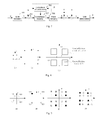
Ref 1,2) only discuss and solve the problem from the amplitude point of view. The inventor of the application thinks that the modulation phase should also be considered to reconstruct v from the received signal y optimally. Especially in case that interference signal s has larger amplitude than that of intended signal v, it is quite difficult for the prior arts to reconstruct the phase of intended signal.Fig. 2 and Fig. 3 show the problem of prior art in case of BPSK and QPSK respectively. For simplicity, assuming that v and s have the same modulation constellation. The interference signal s has higher amplitude than intended signal v. InFig. 2 different constellation points of v are distinguished by different shapes while different constellation points of s are distinguished by different shadow fillings. Operation (v-s) inFig. 1 results in the constellation points as shown inFig. 2(c) . Each constellation point shown inFig. 2(c) has both information (comprising amplitude and phase information) of intended signal v and the interference signal s. Then modulo operation of the difference signal (v-s) will decrease the distance between different constellation points in the same quadrant. Thus, the possible constellation points of the received signal y are shown inFig. 2d . It can be seen that the constellation of the received signal y is the enlarged constellation of signal v from QPSK to 16QAM. Furthermore, for the received signal y, different constellation points with same shapes and different shadow fillings are isolated at different quadrants. Obviously, phase reconstruction of intended signal v from the received signal y can hardly achieve. The case of QPSK is shown inFig. 3 , which has the similar problem toFig. 2 . -
Ref 3 is an improvement of THP method described inRefs Fig. 4 illustrates the principle structure of SDPC, where the source signal u is performed by quadrature amplitude modulation. By precoding the modulated signal v, since the receiver side has known the modulation structure of the interference signal and the receiver has also prior knowledge of the constellation of the received signal y; therefore, SDPC has better demodulation performance than THP. However, the phase reconstruction problem is solved to some extend at the cost that the receiver knows the modulation structure of the interference signal. This problem is shown inFigure 5 . What's more, in case that source signal and interference signal are both QPSK, the receiver side has to perform 16QAM decoding on the received signal y whose constellation is enlarged to reconstruct the phase of source signal. -
Ref - Ref 1: H. Harashima and H. Miyakawa, "Matched Transmition technique for channels with intersymbol interference", IEEE Trans. Commun., vo120, pp. 774-780, Aug 1972
- Ref 2: W. Yu and J. M. Cioffi, "Trellis precoding for the broadcast channel", in Proc. IEEE Global Telecommunications Conf. (GLOBLECOM'2001)
- Ref 3: Bin Liu, Hui Liu, Sumit Roy, "Structured dirty paper coding with known Interference structure at receiver", IEEE Signal Systems and Computers, 2005
- The present invention is proposed in order to overcome the aforesaid drawbacks. Therefore, the purpose of the present invention is a dirty paper precoding method and transmitter implemented by using phase reshaping at the transmitter side. A good BER-Eb/N0 performance can be achieved no matter whether the amplitude of interference signal is larger, smaller or equal to the intended signal.
- In order to achieve aforesaid purpose, a dirty paper precoding method implemented by using phase reshaping at the transmitter side is proposed according to the present invention, comprising: subtracting interference signal from intended signal to obtain difference signal; determining constellation size for constellation extension according to amplitude-related information of interference signal and intended signal; extendedly mapping original constellation block of the difference signal to extended constellation block having the determined constellation size by constellation extension processing, according to the determined constellation size for constellation extension, the extended constellation block being proportionally enlarged to be closer to origin of constellation coordinate compared with original constellation block; and performing phase reshaping of each constellation point of extended constellation block corresponding to the difference signal, the phase reshaping making constellation point of extended constellation block of difference signal corresponding to specific constellation point of intended signal to be mapped into the same constellation quadrant as that of the specific constellation point.
- Preferably, the amplitude-related information is amplitudes of intended signal and interference signal.
- Preferably, the amplitude-related information is constellation block size of interference signal and constellation block size of intended signal.
- Preferably, the intended signal is modulated signal.
- Furthermore, a transmitter for implementing dirty paper precoding method by using phase reshaping is proposed according to the present invention, comprising: means for obtaining difference signal, for subtracting interference signal from intended signal to obtain difference signal; means for determining constellation size, for determining constellation size for constellation extension according to amplitude-related information of interference signal and intended signal; means for extended constellation mapping, for extendedly mapping original constellation block of the difference signal to extended constellation block having the determined constellation size by constellation extension processing, according to the determined constellation size for constellation extension, the extended constellation block being proportionally enlarged to be closer to origin of constellation coordinate compared with original constellation block; and means for phase reshaping, for performing phase reshaping of each constellation point of extended constellation block corresponding to the difference signal, the phase reshaping making constellation point of extended constellation block of difference signal corresponding to specific constellation point of intended signal to be mapped into the same constellation quadrant as that of the specific constellation point.
- Preferably, the amplitude-related information is amplitudes of intended signal and interference signal.
- Preferably, the amplitude-related information is constellation block size of interference signal and constellation block size of intended signal.
- Preferably, the transmitter further comprises: modulation means for modulating source signal to obtain the intended signal.
- By referring to the detailed description of the used preferable embodiments with reference to the following drawings, aforesaid objects, advantages and features of the present invention will become apparent, wherein:
-
Fig.1 is a structural schematic diagram for implementing traditional Tomlinson-Harashima precoding; -
Fig.2 is a constellation for each signal of THP in case of BPSK (Binary Phase Shift Keying); -
Fig.3 is a constellation for each signal of THP in case of QPSK (Quadrature Phase Shift Keying); -
Fig.4 is a structural schematic diagram of the SDPC precoding in the prior art; -
Fig.5 is a constellation for each signal of SDPC in case of QPSK (Quadrature Phase Shift Keying); -
Fig.6 is a flowchart of a dirty paper precoding method implemented by using phase reshaping at the transmitter side according to the present invention; -
Fig.7 is structural diagram of implementing dirty paper precoding by using phase reshaping according to the present invention; -
Fig.8 is a schematic diagram of determining constellation size for constellation extension according to a first embodiment of the present invention; -
Fig.9 is a constellation of each signal according to the first embodiment of the present invention; -
Fig.10 is a schematic diagram of determining constellation size for constellation extension according to a second embodiment of the present invention; -
Fig.11 is curve graph of BER performance comparison between the method of the present invention and the SDPC precoding in the prior art. - In the followings, the preferable embodiments of the present invention are described with reference to the drawings.
-
Fig.6 is a flowchart of a dirty paper precoding method implemented by using phase reshaping at the transmitter side according to the present invention. - As shown in
Fig.6 , instep 601, subtracting interference signal s from intended signal v to obtain difference signal b. - In
step 603, determining constellation size for constellation extension according to amplitude-related information of intended signal v and interference signal s. -
Fig.8 is a schematic diagram of determining constellation size for constellation extension according to a first embodiment of the present invention. - As shown in
Fig. 8 , the transmitter determines the constellation size for constellation extension of difference signal b according to amplitude of intended signal v and interference signal s (v1 and s1 inFig.8 ). From the example shown in (a) and (b) ofFig.8 , it is seen that both intended signal and interference signal are QPSK modulated. The constellation size of intended signal v and interference signal s can be determined via amplitude v1 and s1. - The constellation size of difference signal b is determined by ± L1 and ± L2. In other words, for example in the first quadrant, x-coordinate and y-coordinate of constellation point of difference signal b are both within the range [L2, L1].
- Assuming s1 = α·v1, where α > 0, L1 and L2 are determined according to the following rules:


- The determining process of constellation size is applicable no matter how the power ratio between intended signal v and interference signal s is.
-
Fig.10 is a schematic diagram of determining constellation size for constellation extension according to a second embodiment of the present invention. Wherein, one or both of intended signal v and interference signal s are QAM modulation being higher than QPSK. - As shown in
Fig. 10 (a) , the constellation block of intended signal v can be determined by the location of constellation center in each quadrant and parameters of constellation block size (that is, v1 and v2). As shown inFig.10 (b) , the constellation block of interference signal s can be determined by the location of constellation center in each quadrant and parameters of constellation block size (that is, s1 and s2). Wherein, the constellation block is set defined by coordinates of all the constellation points of signal in a certain quadrant. - Assuming s1 = α1·v1, s2 = ct2 . v2 , wherein α1,α2 > 0, then: L1 and L2 are determined according to the following rules:


- In
step 605, extendedly mapping original constellation block of the difference signal b to extended constellation block, namely constellation block of output signal c, having the determined constellation size ± L1 and ± L2 by constellation extension processing, according to the determined constellation size ± L1 and ± L2 for constellation extension. It can be seen that the extended constellation block, by constellation extension processing, is proportionally enlarged to be closer to origin of constellation coordinate compared with original constellation block. - As shown in
Fig.8 , the original constellation size of difference signal b in x-coordinate and y-coordinate are both within the range [|α-1|·v1, (1+α)·v1]. The original constellation block is proportionally mapped into the extended constellation block of output signal c (for example in the first quadrant, x-coordinate and y-coordinate of constellation point are both within the range [L2, L1]) by constellation extension. Wherein, it needs to be pointed out in advance, the constellation block of the output signal d obtained via the phase reshaping, which will be described later, of output c, has the same size with that of the extended constellation block of output signal c. - In
step 607, performing phase reshaping of each constellation point of extended constellation block c corresponding to the difference signal b. Wherein, the phase of signal denotes in which quadrant of constellation its constellation point is located. The phase reshaping makes constellation point (constellation point of the output signal c)of extended constellation block of difference signal b corresponding to specific constellation point of intended signal v to be mapped into the same constellation quadrant as that of the specific constellation point, to obtain the constellation point of output signal d. - The phase of each constellation point of extended constellation block of difference signal b is reshaped according to the phase of the intended signal v in the following way:


- In other words, this means mapping constellation point of signal c comprising signal v into the same constellation quadrant as that of signal v, to obtain the constellation point of signal d.
-
Fig.7 is a structural diagram of implementing dirty paper precoding by using phase reshaping according to the present invention. The solid line denotes the same data flow as shown inFig.1 . The function block within the dashed line block P denotes the designed dirty paper precoding strategy before transmitting, the dot and dash line represents control information. - As shown in
Fig.7 , the transmitter according to the present invention comprises: a modulation means 701, ameans 703 for obtaining difference signal, ameans 705 for determining constellation size, ameans 707 for extended constellation mapping, ameans 709 for phase reshaping. The modulation means 701 is used for modulating source signal to obtain the intended signal. The means 703 for obtaining difference signal subtracts interference signal from intended signal to obtain difference signal. The means 705 for determining constellation size determines constellation size for constellation extension according to amplitude-related information of interference signal and intended signal. The means 707 for extended constellation mapping extendedly maps original constellation block of the difference signal to extended constellation block having the determined constellation size by constellation extension processing, according to the determined constellation size for constellation extension, the extended constellation block is proportionally enlarged to be closer to origin of constellation coordinate compared with original constellation block. The means 709 for phase reshaping performs phase reshaping of each constellation point of extended constellation block corresponding to the difference signal, the phase reshaping makes constellation point of extended constellation block of difference signal corresponding to specific constellation point of intended signal to be mapped into the same constellation quadrant as that of the specific constellation point. - Furthermore, as shown in
Fig. 9 , the received signal y at the receiver side keeps the phase feature of intended signal v for the reason of phase reshaping at the transmitter side, according to the present invention. Therefore, compared with the prior arts, the receiver does not need to know the modulation structure of interference signal while restructuring the intended signal according to the present invention. Furthermore, that the receiver knows the modulation structure of interference signal will narrow the application scenarios. While using THP coding to eliminate multi-user interference, it is almost impossible for the receiver to know the modulation structure of interference signal. On the other hand, according to the present invention, the receiver will not demodulate the modulated constellation (constellation of output signals c and d) after modulation extension. -
Fig.11 is a curve graph of BER performance comparison between the method of the present invention and the SDPC precoding in the prior art. - As shown in
Fig. 11 , the performance curve is BER to Eb/N0 of OFDM signal. In the simulation, intended signal and interference signal of DPC are both QPSK modulated signal, a =1.5, coding scheme at the transmitter side uses turbo code withcode rate 1/3, the transmitting signal in the channel is OFDM signal. The receiver side uses efficient logarithm maximum a posteriori probability criteria decoding algorithm, that is, Max-log-MAP decoding algorithm. Other simulation parameters are: FFT size of OFDM signal is 512 points, channel estimation algorithm uses ideal channel estimation, channel type is AWGN single input single output channel, system bandwidth is 5M, and subcarrier OFDM interval is 15Hz. As a reference, the performance in case of AWGN channel without interference is shown inFig. 11 . The result shows that the method according to the present invention has about 4dB improvement compared with SDPC of the prior arts. - The detailed advantages of the present invention are listed as following:
- 1) achieving dirty paper precoding with better performance;
- 2) the present invention improves THP precoding method by considering constellation size and phase;
- 3) modulo operation at the receiver side is not needed compared with traditional THP precoding;
- 4) the present invention can be applied well no matter whether the amplitude of interference signal is larger, smaller or equal to the intended signal.
- 5) the receiver does not need to know the modulation structure of interference signal. Furthermore, that the receiver knows the modulation structure of interference signal will narrow the application scenes;
- 6) the receiver only needs to demodulate the received signal according to the modulation structure of the transmitted signal, and needs not to demodulate the actual modulation structure of the received signal whose constellation is enlarged compared with the transmitted signal;
- 7) the present invention enables the received signal to keep the same phase feature as the intended signal carried by it, so the present invention have better demodulation performance compared with the prior arts;
- 8) the present invention is a more applicable implementation of DPC, and has better BER-Eb/N0 performance compared with the prior arts.
- Although the present invention is shown above in combination with preferable embodiments of the present invention, the skilled in the art will understand that the present invention can be modified, replaced and changed without violating the spirit and scope of the present invention. Therefore, the present invention should not be limited by aforesaid embodiments, but be defined by the appended claims and their equivalents.
Claims (8)
- A dirty paper precoding method implemented by using phase reshaping at the transmitter side, wherein the method comprises:subtracting interference signal from intended signal to obtain difference signal;determining constellation size for constellation extension according to amplitude-related information of interference signal and intended signal;extendedly mapping original constellation block of the difference signal to extended constellation block having the determined constellation size by constellation extension processing, according to the determined constellation size for constellation extension, the extended constellation block being proportionally enlarged to be closer to origin of constellation coordinate compared with original constellation block; andperforming phase reshaping of each constellation point of extended constellation block corresponding to the difference signal, the phase reshaping making constellation point of extended constellation block of difference signal corresponding to specific constellation point of intended signal to be mapped into the same constellation quadrant as that of the specific constellation point.
- The method according to claim 1, characterized in that, the amplitude-related information is amplitudes of intended signal and interference signal.
- The method according to claim 1, characterized in that, the amplitude-related information is constellation block size of interference signal and constellation block size of intended signal.
- The method according to claim 1, characterized in that, the intended signal is modulated signal.
- A transmitter for implementing dirty paper precoding method by using phase reshaping, wherein the transmitter comprises:a means for obtaining difference signal, for subtracting interference signal from intended signal to obtain difference signal;a means for determining constellation size, for determining constellation size for constellation extension according to amplitude-related information of interference signal and intended signal;a means for extended constellation mapping, for extendedly mapping original constellation block of the difference signal to extended constellation block having the determined constellation size by constellation extension processing, according to the determined constellation size for constellation extension, the extended constellation block being proportionally enlarged to be closer to origin of constellation coordinate compared with original constellation block; anda means for phase reshaping, for performing phase reshaping of each constellation point of extended constellation block corresponding to the difference signal, the phase reshaping making constellation point of extended constellation block of difference signal corresponding to specific constellation point of intended signal to be mapped into the same constellation quadrant as that of the specific constellation point.
- The transmitter according to claim 5, characterized in that the amplitude-related information is amplitudes of intended signal and interference signal.
- The transmitter according to claim 5, characterized in that, the amplitude-related information is constellation block size of interference signal and constellation block size of intended signal.
- The transmitter according to claim 5, characterized in further comprising: modulation means for modulating source signal to obtain the intended signal.
Applications Claiming Priority (1)
| Application Number | Priority Date | Filing Date | Title |
|---|---|---|---|
| PCT/CN2009/000196 WO2010096948A1 (en) | 2009-02-24 | 2009-02-24 | Method and transmitter for implementing dirty paper pre-coding by using phase shaping anew |
Publications (2)
| Publication Number | Publication Date |
|---|---|
| EP2403155A1 true EP2403155A1 (en) | 2012-01-04 |
| EP2403155A4 EP2403155A4 (en) | 2012-08-08 |
Family
ID=42664990
Family Applications (1)
| Application Number | Title | Priority Date | Filing Date |
|---|---|---|---|
| EP09840616A Ceased EP2403155A4 (en) | 2009-02-24 | 2009-02-24 | METHOD AND TRANSMITTER FOR IMPLEMENTING DIRTY PAPER PRECODING USING REITRATED PHASE SHAPING |
Country Status (7)
| Country | Link |
|---|---|
| US (1) | US8401112B2 (en) |
| EP (1) | EP2403155A4 (en) |
| JP (1) | JP5340422B2 (en) |
| KR (1) | KR101200707B1 (en) |
| CN (1) | CN102246424B (en) |
| BR (1) | BRPI0924473A2 (en) |
| WO (1) | WO2010096948A1 (en) |
Cited By (1)
| Publication number | Priority date | Publication date | Assignee | Title |
|---|---|---|---|---|
| US9270509B1 (en) | 2014-12-15 | 2016-02-23 | Apple Inc. | Devices and methods for orthogonal frequency division multiplexing signal phase shaping |
Families Citing this family (4)
| Publication number | Priority date | Publication date | Assignee | Title |
|---|---|---|---|---|
| JP5596498B2 (en) * | 2010-11-02 | 2014-09-24 | シャープ株式会社 | Base station apparatus, mobile station apparatus, and wireless communication system using them |
| KR102032212B1 (en) | 2013-02-28 | 2019-10-15 | 삼성전자 주식회사 | Method and apparatus for cancelling an interference in wireless communication system |
| KR20160048360A (en) * | 2014-10-24 | 2016-05-04 | 삼성전자주식회사 | method and apparatus for receiving a signal based on a measurement of interference |
| US10270478B2 (en) | 2015-07-27 | 2019-04-23 | Northrop Grumman Systems Corporation | Non-linear transmitter pre-coding |
Family Cites Families (9)
| Publication number | Priority date | Publication date | Assignee | Title |
|---|---|---|---|---|
| US6792049B1 (en) * | 2000-06-15 | 2004-09-14 | Mitsubishi Electric Research Laboratories, Inc. | Digital transceiver system with adaptive channel pre-coding in an asymmetrical communications network |
| DE10044227A1 (en) * | 2000-09-07 | 2002-04-04 | Nanotron Ges Fuer Mikrotechnik | Method for coding and decoding an information symbol |
| KR20060093332A (en) * | 2003-10-21 | 2006-08-24 | 코닌클리즈케 필립스 일렉트로닉스 엔.브이. | Transmitters, Receivers, Transceivers, Wireless Devices, and Telecommunication Systems |
| US7508882B2 (en) * | 2003-12-04 | 2009-03-24 | Alcatel-Lucent Usa Inc. | Electrical backplane transmission using duobinary signaling |
| CN100396063C (en) | 2004-09-03 | 2008-06-18 | 清华大学 | Method based on joint differential amplitude and phase modulation for global digital broadcasting |
| CN1870459A (en) * | 2005-05-24 | 2006-11-29 | 松下电器产业株式会社 | Multi-user multi-input multi-output cross-layer communication method of joint dirty paper code and dispatching |
| WO2007044484A2 (en) * | 2005-10-07 | 2007-04-19 | University Of Washington | Dirty paper precoding with known interference structure at receiver |
| WO2008073335A2 (en) * | 2006-12-07 | 2008-06-19 | Nokia Siemens Networks Gmbh & Co. Kg | Cooperative relaying using dirty paper coding |
| US8009757B2 (en) * | 2007-11-12 | 2011-08-30 | Motorola Mobility, Inc. | Method and apparatus for encoding a modulated signal in a communication system |
-
2009
- 2009-02-24 WO PCT/CN2009/000196 patent/WO2010096948A1/en not_active Ceased
- 2009-02-24 US US13/202,859 patent/US8401112B2/en not_active Expired - Fee Related
- 2009-02-24 CN CN2009801495812A patent/CN102246424B/en active Active
- 2009-02-24 EP EP09840616A patent/EP2403155A4/en not_active Ceased
- 2009-02-24 KR KR1020117022018A patent/KR101200707B1/en not_active Expired - Fee Related
- 2009-02-24 JP JP2011551384A patent/JP5340422B2/en not_active Expired - Fee Related
- 2009-02-24 BR BRPI0924473A patent/BRPI0924473A2/en not_active Application Discontinuation
Non-Patent Citations (6)
| Title |
|---|
| BIN LIU ET AL: "DPC-Based Hierarchical Broadcasting: Design and Implementation", IEEE TRANSACTIONS ON VEHICULAR TECHNOLOGY, vol. 57, no. 6, 1 November 2008 (2008-11-01), pages 3895-3900, XP011225245, IEEE SERVICE CENTER, PISCATAWAY, NJ, US ISSN: 0018-9545, DOI: 10.1109/TVT.2008.919610 * |
| HUA CHAO ET AL: "Dirty Paper Coding with phase reshaping: New integration scheme for broadcast and unicast", IEEE 20TH INTERNATIONAL SYMPOSIUM ON PERSONAL, INDOOR AND MOBILE RADIO COMMUNICATIONS (PIMRC 2009), 13 September 2009 (2009-09-13), pages 2355-2359, XP031659615, IEEE, PISCATAWAY, NJ, USA ISBN: 978-1-4244-5122-7 * |
| HUPPERT C ET AL: "On Tomlinson-Harashima precoding in 2-user degraded Gaussian broadcast channels", INFORMATION THEORY AND ITS APPLICATIONS, 7 December 2008 (2008-12-07), pages 1-6, XP031451258, IEEE, PISCATAWAY, NJ, USA ISBN: 978-1-4244-2068-1 * |
| JIANG H ET AL: "A Hierarchical Modulation for Upgrading Digital Broadcast Systems", IEEE TRANSACTIONS ON BROADCASTING, vol. 51, no. 2, 1 June 2005 (2005-06-01), pages 223-229, XP011132694, IEEE SERVICE CENTER, PISCATAWAY, NJ, US ISSN: 0018-9316, DOI: 10.1109/TBC.2005.847619 * |
| See also references of WO2010096948A1 * |
| YUK-LUN CHAN ET AL: "Modified TH-precoding with constant amplitude for indoor wireless system using QPSK", VEHICULAR TECHNOLOGY CONFERENCE, vol. 2, 28 April 1996 (1996-04-28), - 1 May 1996 (1996-05-01), pages 810-814, XP010162501, NEW YORK, NY, USA,IEEE, US DOI: 10.1109/VETEC.1996.501423 ISBN: 978-0-7803-3157-0 * |
Cited By (1)
| Publication number | Priority date | Publication date | Assignee | Title |
|---|---|---|---|---|
| US9270509B1 (en) | 2014-12-15 | 2016-02-23 | Apple Inc. | Devices and methods for orthogonal frequency division multiplexing signal phase shaping |
Also Published As
| Publication number | Publication date |
|---|---|
| EP2403155A4 (en) | 2012-08-08 |
| KR20110129412A (en) | 2011-12-01 |
| CN102246424A (en) | 2011-11-16 |
| JP2012518959A (en) | 2012-08-16 |
| JP5340422B2 (en) | 2013-11-13 |
| WO2010096948A1 (en) | 2010-09-02 |
| US8401112B2 (en) | 2013-03-19 |
| US20110305298A1 (en) | 2011-12-15 |
| BRPI0924473A2 (en) | 2016-02-16 |
| CN102246424B (en) | 2013-09-11 |
| KR101200707B1 (en) | 2012-11-13 |
Similar Documents
| Publication | Publication Date | Title |
|---|---|---|
| Sathananthan et al. | Probability of error calculation of OFDM systems with frequency offset | |
| Li et al. | Channel capacity of IM/DD optical communication systems and of ACO-OFDM | |
| JP4563455B2 (en) | Method and apparatus for calculating log approximation rate for decoding in receiver of mobile communication system | |
| US6654340B1 (en) | Differential OFDM using multiple receiver antennas | |
| CN107948113A (en) | Being inserted into based on three dimensional signal reduces the method and system of ofdm system peak-to-average power ratio | |
| EP2403155A1 (en) | Method and transmitter for implementing dirty paper pre-coding by using phase shaping anew | |
| CN106941470A (en) | A kind of method of signal peak-to-average ratio in reduction FBMC systems | |
| CN101848184A (en) | Selective mapping scrambling method for reducing peak-to-average power ratio of orthogonal frequency division multiplexing system | |
| KR102061653B1 (en) | Method and apparatus for bit to simbol mapping in wireless communication system | |
| US20100135421A1 (en) | Apparatus and method for reducing peak to average power ration in orthogonal frequency division multiplexing system | |
| US7586991B2 (en) | Method and apparatus for calculating likelihood metric of a received signal in a digital communication system | |
| CN103237001A (en) | Advanced Metering Infrastructure (AMI) system carrier communication module self-adaptive modulation and coding method | |
| US9473244B2 (en) | Flexible 400G and 1 Tb/s transmission over transoceanic distance | |
| KR20150081993A (en) | Method for transmitting and receiving signal in OFDM system and apparatus thereof | |
| Reddy et al. | MSE and BER analysis of text, audio and image transmission using ML based OFDM | |
| CN115173958B (en) | Method for realizing unequal error protection of underwater multimedia data transmission based on optical OFDM | |
| CN111131107B (en) | An adaptive soft demodulation method based on 5G downlink shared channel state | |
| CN118679718A (en) | Unified and configurable waveform framework for 6G | |
| KR100391565B1 (en) | An Rayleigh Fading Compensation Method with Modified Sinc Interpolation | |
| Tarerefa et al. | Performance Analysis of OFDM signal using Different Modulation Schemes with Least Square Channel Estimation Technique | |
| US8982988B2 (en) | Apparatus and method for transmitting and receiving signal of OFDM system | |
| CN110855588B (en) | Frequency domain adaptive equalization transmission data processing method, data receiving end and storage medium | |
| KR20120104824A (en) | Soft bit decision demodulator | |
| KR101294788B1 (en) | Transmission method for dual digital signal through single antenna, transmitter for dual digital signal through single antenna and receiving method for dual digital signal through single antenna | |
| CN121967143A (en) | Sensing Interleaved Frequency Division Multiplexing Waveform System for Integrated Communication and Sensing |
Legal Events
| Date | Code | Title | Description |
|---|---|---|---|
| PUAI | Public reference made under article 153(3) epc to a published international application that has entered the european phase |
Free format text: ORIGINAL CODE: 0009012 |
|
| 17P | Request for examination filed |
Effective date: 20110926 |
|
| AK | Designated contracting states |
Kind code of ref document: A1 Designated state(s): AT BE BG CH CY CZ DE DK EE ES FI FR GB GR HR HU IE IS IT LI LT LU LV MC MK MT NL NO PL PT RO SE SI SK TR |
|
| RAP1 | Party data changed (applicant data changed or rights of an application transferred) |
Owner name: ALCATEL LUCENT |
|
| DAX | Request for extension of the european patent (deleted) | ||
| A4 | Supplementary search report drawn up and despatched |
Effective date: 20120706 |
|
| RIC1 | Information provided on ipc code assigned before grant |
Ipc: H04J 11/00 20060101ALI20120702BHEP Ipc: H04L 27/34 20060101ALI20120702BHEP Ipc: H04L 25/497 20060101AFI20120702BHEP Ipc: H04L 1/00 20060101ALI20120702BHEP |
|
| 17Q | First examination report despatched |
Effective date: 20130412 |
|
| 111Z | Information provided on other rights and legal means of execution |
Free format text: AT BE BG CH CY CZ DE DK EE ES FI FR GB GR HR HU IE IS IT LI LT LU LV MC MK MT NL NO PL PT RO SE SI SK TR Effective date: 20130410 |
|
| RAP1 | Party data changed (applicant data changed or rights of an application transferred) |
Owner name: ALCATEL LUCENT |
|
| D11X | Information provided on other rights and legal means of execution (deleted) | ||
| RAP1 | Party data changed (applicant data changed or rights of an application transferred) |
Owner name: ALCATEL LUCENT |
|
| STAA | Information on the status of an ep patent application or granted ep patent |
Free format text: STATUS: EXAMINATION IS IN PROGRESS |
|
| REG | Reference to a national code |
Ref country code: DE Ref legal event code: R003 |
|
| STAA | Information on the status of an ep patent application or granted ep patent |
Free format text: STATUS: THE APPLICATION HAS BEEN REFUSED |
|
| 18R | Application refused |
Effective date: 20191028 |