EP2402801A2 - A scalable cladding mode stripper device - Google Patents
A scalable cladding mode stripper device Download PDFInfo
- Publication number
- EP2402801A2 EP2402801A2 EP11169705A EP11169705A EP2402801A2 EP 2402801 A2 EP2402801 A2 EP 2402801A2 EP 11169705 A EP11169705 A EP 11169705A EP 11169705 A EP11169705 A EP 11169705A EP 2402801 A2 EP2402801 A2 EP 2402801A2
- Authority
- EP
- European Patent Office
- Prior art keywords
- cladding
- optical fiber
- block
- cladding mode
- groove
- Prior art date
- Legal status (The legal status is an assumption and is not a legal conclusion. Google has not performed a legal analysis and makes no representation as to the accuracy of the status listed.)
- Withdrawn
Links
- 238000005253 cladding Methods 0.000 title claims abstract description 175
- 239000013307 optical fiber Substances 0.000 claims abstract description 89
- 239000012780 transparent material Substances 0.000 claims abstract description 19
- 230000008878 coupling Effects 0.000 claims description 18
- 238000010168 coupling process Methods 0.000 claims description 18
- 238000005859 coupling reaction Methods 0.000 claims description 18
- 239000000463 material Substances 0.000 claims description 15
- 230000003287 optical effect Effects 0.000 claims description 15
- 238000000034 method Methods 0.000 claims description 9
- 230000000903 blocking effect Effects 0.000 claims description 7
- JNDMLEXHDPKVFC-UHFFFAOYSA-N aluminum;oxygen(2-);yttrium(3+) Chemical compound [O-2].[O-2].[O-2].[Al+3].[Y+3] JNDMLEXHDPKVFC-UHFFFAOYSA-N 0.000 claims description 4
- 229910052594 sapphire Inorganic materials 0.000 claims description 4
- 239000010980 sapphire Substances 0.000 claims description 4
- 229910019901 yttrium aluminum garnet Inorganic materials 0.000 claims description 4
- NIXOWILDQLNWCW-UHFFFAOYSA-M Acrylate Chemical compound [O-]C(=O)C=C NIXOWILDQLNWCW-UHFFFAOYSA-M 0.000 claims description 2
- 239000000919 ceramic Substances 0.000 claims description 2
- 229920001296 polysiloxane Polymers 0.000 claims description 2
- 238000007788 roughening Methods 0.000 claims 1
- 239000000835 fiber Substances 0.000 abstract description 56
- 239000004020 conductor Substances 0.000 abstract 1
- 229920000642 polymer Polymers 0.000 description 10
- 239000011521 glass Substances 0.000 description 7
- 239000011248 coating agent Substances 0.000 description 6
- 238000000576 coating method Methods 0.000 description 6
- 239000007787 solid Substances 0.000 description 4
- VYPSYNLAJGMNEJ-UHFFFAOYSA-N Silicium dioxide Chemical group O=[Si]=O VYPSYNLAJGMNEJ-UHFFFAOYSA-N 0.000 description 2
- 230000008901 benefit Effects 0.000 description 2
- 238000010438 heat treatment Methods 0.000 description 2
- 238000007726 management method Methods 0.000 description 2
- 238000012986 modification Methods 0.000 description 2
- 230000004048 modification Effects 0.000 description 2
- 229910052691 Erbium Inorganic materials 0.000 description 1
- 229910052769 Ytterbium Inorganic materials 0.000 description 1
- 238000013459 approach Methods 0.000 description 1
- 238000000149 argon plasma sintering Methods 0.000 description 1
- 238000003491 array Methods 0.000 description 1
- 230000004888 barrier function Effects 0.000 description 1
- 230000015572 biosynthetic process Effects 0.000 description 1
- 229910010293 ceramic material Inorganic materials 0.000 description 1
- 238000009826 distribution Methods 0.000 description 1
- 238000005553 drilling Methods 0.000 description 1
- 230000000694 effects Effects 0.000 description 1
- 238000005516 engineering process Methods 0.000 description 1
- UYAHIZSMUZPPFV-UHFFFAOYSA-N erbium Chemical compound [Er] UYAHIZSMUZPPFV-UHFFFAOYSA-N 0.000 description 1
- 239000012530 fluid Substances 0.000 description 1
- 239000005350 fused silica glass Substances 0.000 description 1
- 238000007429 general method Methods 0.000 description 1
- 150000002500 ions Chemical class 0.000 description 1
- 229910052751 metal Inorganic materials 0.000 description 1
- 239000002184 metal Substances 0.000 description 1
- 238000013021 overheating Methods 0.000 description 1
- 230000005855 radiation Effects 0.000 description 1
- 229910052761 rare earth metal Inorganic materials 0.000 description 1
- 230000002269 spontaneous effect Effects 0.000 description 1
- 238000012546 transfer Methods 0.000 description 1
- 238000009827 uniform distribution Methods 0.000 description 1
- NAWDYIZEMPQZHO-UHFFFAOYSA-N ytterbium Chemical compound [Yb] NAWDYIZEMPQZHO-UHFFFAOYSA-N 0.000 description 1
Images

Classifications
-
- G—PHYSICS
- G02—OPTICS
- G02B—OPTICAL ELEMENTS, SYSTEMS OR APPARATUS
- G02B6/00—Light guides; Structural details of arrangements comprising light guides and other optical elements, e.g. couplings
- G02B6/24—Coupling light guides
- G02B6/26—Optical coupling means
- G02B6/28—Optical coupling means having data bus means, i.e. plural waveguides interconnected and providing an inherently bidirectional system by mixing and splitting signals
- G02B6/2804—Optical coupling means having data bus means, i.e. plural waveguides interconnected and providing an inherently bidirectional system by mixing and splitting signals forming multipart couplers without wavelength selective elements, e.g. "T" couplers, star couplers
- G02B6/2852—Optical coupling means having data bus means, i.e. plural waveguides interconnected and providing an inherently bidirectional system by mixing and splitting signals forming multipart couplers without wavelength selective elements, e.g. "T" couplers, star couplers using tapping light guides arranged sidewardly, e.g. in a non-parallel relationship with respect to the bus light guides (light extraction or launching through cladding, with or without surface discontinuities, bent structures)
-
- G—PHYSICS
- G02—OPTICS
- G02B—OPTICAL ELEMENTS, SYSTEMS OR APPARATUS
- G02B5/00—Optical elements other than lenses
- G02B5/003—Light absorbing elements
-
- G—PHYSICS
- G02—OPTICS
- G02B—OPTICAL ELEMENTS, SYSTEMS OR APPARATUS
- G02B6/00—Light guides; Structural details of arrangements comprising light guides and other optical elements, e.g. couplings
- G02B6/10—Light guides; Structural details of arrangements comprising light guides and other optical elements, e.g. couplings of the optical waveguide type
- G02B6/14—Mode converters
Definitions
- the present invention relates to fiberoptic devices, and in particular to cladding mode strippers for stripping cladding modes of light from an optical fiber.
- Fiber lasers have significant advantages over traditional lasers, including stability of alignment, scalability, and high optical power of a nearly diffraction limited output beam.
- the gain medium is a length of an optical fiber, the core of which is doped with an active lasing material, typically ions of a rare earth element, such as erbium or ytterbium or both.
- the lasing material is usually pumped using an emission of a diode laser, or an array of diode lasers.
- a doped fused silica core and a fused silica inner cladding or claddings of the fiber lasers are surrounded by an external coating made of a polymer. Having an external polymer coating is essential because without it, the optical fiber becomes very brittle; furthermore, for some fibers called "polymer-clad fibers", the polymer layer functions as an outer optical cladding.
- the polymer-clad fibers the polymer layer functions as an outer optical cladding.
- Even a small fraction of stray light can heat the polymer to a temperature at which it can be damaged, causing catastrophic failure of the active fiber of the laser. For instance, in fiber laser arrangements where the fiber is pumped at one end, and a catastrophic thermal failure occurs at the other end, the fiber can actually start burning towards the pump end, causing the entire length of expensive active double-clad fiber to be eliminated.
- the stray light and associated heating is caused by so called cladding modes, that is, modes of light propagation in the cladding.
- the cladding modes of the inner cladding are used to deliver the pump light to the fiber core.
- the light of the cladding modes escapes the inner cladding, it can cause a localized heating of the fiber polymer coating, resulting in a catastrophic failure of the active fiber.
- the cladding modes need to be removed (stripped) from the fiber where they are no longer required, or where they should not be normally present, such as in outer cladding of a double clad fiber.
- the residual inner cladding light can be removed at the other end of the fiber to prevent its further propagation.
- the cladding modes present in the outermost cladding can be removed at the pump end of the active fiber.
- the cladding light can include the residual (unabsorbed) pump light, amplified spontaneous emission (ASE) of the active fiber core, and the laser light at the wavelength of lasing that escaped the fiber core.
- Cladding modes are removed using so called cladding mode stripper devices, or cladding mode strippers.
- a cladding mode stripper of the prior art has a layer of a high-index material disposed next to and optically coupled to the cladding of the optical fiber. The cladding light present in the cladding is coupled to the high-index material and is absorbed in the high-index material or in an opaque solid shield disposed around the high-index material.
- An index-matching gel or a coating of a high-index polymer is typically used in a cladding mode stripper.
- Wilhelmson et al. in US Patent 4,678,273 which is incorporated herein by reference, disclose a mode stripper having a radiation-resistant high-index material surrounding the optical fiber.
- the refractive index of the high-index polymer can be made to vary along the fiber.
- the refractive index of the high-index polymer can be made to vary along the fiber.
- Frith in US Patent Application Publication 2009/0080835 A1 which is incorporated herein by reference, discloses a "gradual" cladding mode stripper for a multi-cladding fiber, in which the claddings of the fiber are removed one by one in a step-like fashion, the high-index material being placed at the steps where the claddings are removed, to couple the cladding modes out.
- the prior-art approaches are not scalable to very high optical power levels, being specific to particular fiber types and particular optical power ranges.
- the prior art lacks a cladding mode stripper device that would be simple yet scalable to high optical power levels. Accordingly, the present invention provides such a device.
- a cladding mode stripper for stripping a cladding mode of an optical fiber having a core and a first cladding, the cladding mode stripper comprising:
- a cladding mode stripper for stripping a cladding mode of an optical fiber having a core and a first cladding, the cladding mode stripper comprising:
- a method of stripping a cladding mode of an optical fiber having a core and a first cladding comprising:
- FIG. 1 is a side cross-sectional view of a cladding mode stripper of the invention
- FIG. 2 is a cross-sectional view of a channel region of the cladding mode stripper of FIG. 1 , the cross-section being taken along lines A-A in FIG. 1 ;
- FIG. 3 is a cross-sectional view of one embodiment of the channel region, taken along the channel;
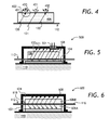
- FIG. 4 is a cross-sectional view of a block of a transparent material having a grooved surface
- FIG. 5 is a side cross-sectional view of a cladding mode stripper having a light sensor for sensing the stripped light;
- FIG. 6 is a side cross-sectional view of another embodiment of a cladding mode stripper of the invention.
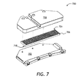
- FIG. 7 is an exploded view of a prototype of the cladding mode stripper of FIG. 1 ;
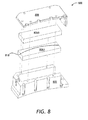
- FIG. 8 is an exploded view of a prototype of the cladding mode stripper of FIG. 6 .
- the mode stripper device 100 has a base 102 having a reflective surface 104; a block 106 of a transparent material, disposed on the base 102 and thermally coupled to the base 102 for conducting heat away from the block 106; an optional opaque cover 108 thermally coupled to the base 102 for blocking light of the stripped cladding modes; and an optional heat sink 110 such as a thermoelectric (TEC) cooler, coupled to the base 102 for removing heat from the base 102.
- TEC thermoelectric
- a bottom surface 107 of the block 106 is placed on the base 102.
- a groove 118 is provided in the block 106 extending from the bottom surface 107. The groove 118 is better seen in FIG.
- An optical fiber 112 having a core 114 and a first cladding 116 is disposed in the groove 118 for the optical fiber 112.
- the first cladding 116 of the optical fiber 112 is optically coupled to the groove 118 for stripping the cladding modes from the first cladding 116 of the optical fiber 112.
- the groove 118 has a depth for receiving the optical fiber 112 so as not to impose a substantial amount of mechanical stress on the optical fiber 112, once the bottom surface 107 of the block 106 is disposed on the reflective surface 104 of the base 102.
- the groove is deep enough to receive at least 80% of the fiber diameter.
- the refractive index of the transparent material of the block 106 is equal to or higher than a refractive index of the first cladding 116 of the optical fiber 112.
- the cladding light couples out of the first cladding 116 of the optical fiber 112 and into the block 106, as shown by dashed arrows 120 and solid arrows 121, the dashed arrows 120 corresponding to the light emitted upwards in FIG. 1 , that is, towards the opaque screen 108, and the solid arrows 121 corresponding to the light emitted downwards in FIG. 1 , that is, towards the reflective surface 104.
- the light 121 Upon reflecting from the reflective surface 104, the light 121 propagates upwards, towards the screen 108, as the solid arrows 121 illustrate; and the screen 108 absorbs the cladding light 121.
- the optical fiber 112 is disposed proximate to, and in thermal contact with, the reflective surface 104 of the base 102.
- the fiber 112 is prevented from overheating because the heat is effectively transferred from the fiber 112 to the base 102 and to the heat sink 110, as schematically shown by black arrows 122. Therefore, in the cladding mode stripping device 100, good heat-sinking of the optical fiber 112 due to proximity to the base 102 is uniquely combined with effective stray light management due to reflective surface 104 of the base 102.
- the good thermal contact results in a temperature increase of the fiber 112 of less than 0.1 °C per every Watt of stripped optical power.
- an air gap 124 is provided between the block 106 and the opaque cover 108, for lessening thermal coupling between the block 106 and the opaque cover 108.
- the heat sink 110 and the base 102 can be combined into a single element, and/or the cover 108 can be connected directly to the heat sink 110.
- the cover 108 is shown physically and thermally connected to both the heat sink 110 and the base 102.
- the cladding mode stripper 100 is scalable to high optical power levels of the cladding modes.
- the power handling capability of the cladding mode stripper 100 depends on the overall dimensions of the block 106 and the base 102, as well as the length of the groove 118. By scaling up these dimensions, very high power handling capability can be achieved. It has been experimentally demonstrated that a prototype of the cladding mode stripper 100 is capable of handling at least 150W of stripped optical power.
- a region of the channel 118 of the mode stripper device 100 is shown in a cross-sectional view.
- the cross-section is taken along lines A-A in FIG. 1 .
- a layer 200 of an index-matching fluid or a gel is disposed in the groove 118 at least partially surrounding the optical fiber 112 for improving the optical coupling between the first cladding 116 of the optical fiber 112 and the groove 118 of the block 106.
- the layer 200 functions to improve thermal coupling between the fiber 112 and the base 102.
- the layer 200 can include a silicone, an acrylate, or a sol-gel material.
- the block 106 can be made of a transparent material with a thermal conductivity of preferably better than 0.5 W/(m*K). Sapphire is an excellent material for this application due to its high thermal conductivity of greater than 20W/(m*K), high transparency, and excellent mechanical properties.
- the block 106 can be also made partially absorbing, in which case yttrium aluminum garnet (YAG) material may be appropriate.
- YAG yttrium aluminum garnet
- the block 106 can be made of an optical ceramic material, such as a ceramic YAG.
- the block 106 has a shape of a rectangular parallelepiped. Other shapes can of course be used.
- the groove 118 is shown as having a rectangular cross section.
- the groove 118 can also have a cross section of a different shape, such as cylindrical or polygonal cross section.
- the groove 118 can be made to include a section curved in a plane of the bottom surface 107 of the block 106 to enable the fiber 112 to be laid out in the groove 118 with a slight bend. An example of such a groove will be shown below.
- the optical fiber 112 can be a double clad or a multiclad optical fiber having a second cladding, not shown, disposed around the first cladding 116.
- the second cladding of the optical fiber 112 can be at least partially removed along a length of the optical fiber 112 disposed in the groove 118, so as to optically couple the first cladding 116 to the groove 118.
- the optical fiber 112 can be an active optical fiber, that is a fiber having a core doped with an amplifying material.
- the optical fiber 112 can be a singlemode or a multimode fiber. When it is the cladding mode light in the second cladding that needs to be stripped, the second cladding need not be removed.
- the optical fiber 112 also can be tapered to improve cladding mode stripping performance of the cladding mode stripper 100.
- FIG. 3 a longitudinal cross-sectional view of a region of the channel 118 is shown.
- a fiber 312 having a core 314 surrounded by a cladding 316 is tapered along a fraction 300 of its length.
- an angle which cladding beams 320A to 320D form with the core 314, increases in going from the beam 320A to the beam 320D.
- the increased angle facilitates cladding modes removal along the entire tapered section 300.
- FIG. 4 a cross-sectional view of a block 406 is shown.
- the block 406 corresponds to the block 106 of the cladding mode stripper 100 of FIG. 1 and serves the same purpose as the block 106.
- the difference between the blocks 406 and 106 is that the block 406 has a grooved surface 401, shown in a magnified insert 400, for scattering the light beams 120 and 121 of the stripped cladding modes, as shown schematically with arrows 420 and 421, respectively.
- the scattering prevents the beams 120 and 121 from reflecting from outer faces of the block 406 back into the block 406 and forming "hot spots" or re-entering the optical fiber 112.
- the surface 401 can be roughened to a "milky" appearance, for the same purpose.
- a cladding mode stripper device 500 is shown in a side cross-sectional view.
- the cladding mode stripper device 500 has a light sensor 501 mounted in the screen 108 disposed in a suitable location for sensing the optical power of the stripped light beams 120, 121.
- the optical power of the stripped light measured by the light sensor 501 can be used for controlling purposes, for example to ensure that the stripped optical power does not exceed a pre-determined level.
- a cladding mode stripper device 600 is shown in a side cross-sectional view.
- the cladding mode stripper device 600 differs from the cladding mode stripper 100 in that it has two blocks 606A and 606B of instead of one block 106.
- the first block 606A is disposed on the base 102 and is thermally coupled to the base 102 for conducting heat away from the first block 606A.
- the first block 606A contacts the second block 606B.
- One or both of the joined surfaces of the first and the second blocks 606A and 606B have a groove 618 for the optical fiber 112.
- the first cladding 116 of the optical fiber 112 is optically coupled to the groove 618 for stripping the cladding mode light from the first cladding 116 of the optical fiber 112.
- the joined surfaces of the first and the second blocks 606A and 606B are thermally and optically coupled to each other, for conducting heat and light away from the optical fiber 112.
- the air gap 124 is left between the second block 606B and the opaque cover 108, for lessening thermal coupling between the second block 606B and the opaque cover 108.
- the first block 606A provides a barrier between the index matching gel 200 and the base 102.
- the first block 606A can be manufactured from a material having a high thermal conductivity, such as sapphire; also for effective heat transfer, the first block 606A can be made as thin as can be reasonably manufactured.
- the first block 606A is made of sapphire, it can be made as thin as 1mm, although a thickness of 2mm is more practical.
- increasing the thickness of the first block 606A helps one to avoid formation of hot spots because the light diverges more from the fiber 112 when the thickness is increased.
- One practical range of thickness of the first block 606A is between 1mm and 25mm.
- the base 102 is reflective, but the cladding mode stripper 600 will work even when the base 102 is not reflective, or is partially reflective.
- the base 102 is not 100% reflective, for example 75% reflective or less, more light energy is directed towards the heat sink 110, which may be desirable in certain cases.
- the cladding mode stripper 700 is similar to the cladding mode stripper 100.
- the cladding mode stripper 700 has a reflective base 702, a glass block 706, and an opaque cover 708.
- the reflective base 702 and the opaque cover 708 are attached to a heat sink, not shown.
- the glass block 706 has a curved groove 718 on its bottom surface for the fiber, not shown.
- An upper surface 701 of the glass block 706 is grooved, similarly to the grooved surface 401 of the glass block 406 in FIG. 4 .
- FIG. 8 an exploded view of a prototype of a cladding mode stripper 800 is shown.
- the cladding mode stripper 700 is similar to the cladding mode stripper 400.
- the cladding mode stripper 800 has a base 802, two glass blocks 806A and 806B, and an opaque cover 808.
- the opaque cover 808 is attached to the base 802 enclosing the glass blocks 806A and 806B.
- the bottom glass block 806A has a curved groove 818 on its top surface for the fiber, not shown.
- a general method of stripping a cladding mode of the optical fiber 112 includes the following steps:
- the method also includes the following steps:
- the cladding mode strippers 100, 500, 600, 700, and 800 of the invention, as well as the methods of the invention, can be used to strip cladding modes in fiber lasers, fiber amplifiers, in fiber delivery systems such as delivery fibers for high-power diode lasers or diode laser arrays, and in other systems where cladding mode management is required.
Landscapes
- Physics & Mathematics (AREA)
- General Physics & Mathematics (AREA)
- Optics & Photonics (AREA)
- Light Guides In General And Applications Therefor (AREA)
- Optical Fibers, Optical Fiber Cores, And Optical Fiber Bundles (AREA)
- Lasers (AREA)
- Optical Couplings Of Light Guides (AREA)
Abstract
A cladding mode stripper for stripping cladding modes from an optical fiber is disclosed. The cladding mode stripper includes a reflective base and a block of a transparent material disposed on the reflective base. The block of the transparent material has a groove in its bottom surface for the fiber. The fiber is thermally coupled to the base and optically coupled to the groove in the block, for example using an index matching gel. The cladding mode light is reflected from the reflective base and is absorbed in a cover enclosing the block. An additional thin block of transparent heat-conductive material can be placed between the fiber and the reflective base, to prevent the index matching gel from contacting the reflective surface of the base.
Description
- The present invention relates to fiberoptic devices, and in particular to cladding mode strippers for stripping cladding modes of light from an optical fiber.
- Fiber lasers have significant advantages over traditional lasers, including stability of alignment, scalability, and high optical power of a nearly diffraction limited output beam. In a fiber laser, the gain medium is a length of an optical fiber, the core of which is doped with an active lasing material, typically ions of a rare earth element, such as erbium or ytterbium or both. The lasing material is usually pumped using an emission of a diode laser, or an array of diode lasers. The advent of double clad active optical fibers having inner and outer claddings, in which the pump light is coupled to the inner cladding to be absorbed at the doped fiber core along the fiber length, allowed a considerable increase in overall output power of a fiber laser, while preserving the brightness and directivity of a singlemode output laser beam. Power levels of the order of several kilowatts or even tens of kilowatts in an almost singlemode output laser beam are now achievable, opening a great variety of industrial applications, such as concrete drilling or sheet metal cutting for a car industry or shipbuilding.
- At high optical power levels of fiber lasers, the task of managing stray light becomes crucial. A doped fused silica core and a fused silica inner cladding or claddings of the fiber lasers are surrounded by an external coating made of a polymer. Having an external polymer coating is essential because without it, the optical fiber becomes very brittle; furthermore, for some fibers called "polymer-clad fibers", the polymer layer functions as an outer optical cladding. At high pump power levels, even a small fraction of stray light can heat the polymer to a temperature at which it can be damaged, causing catastrophic failure of the active fiber of the laser. For instance, in fiber laser arrangements where the fiber is pumped at one end, and a catastrophic thermal failure occurs at the other end, the fiber can actually start burning towards the pump end, causing the entire length of expensive active double-clad fiber to be eliminated.
- In fiber lasers, the stray light and associated heating is caused by so called cladding modes, that is, modes of light propagation in the cladding. In double clad fibers, the cladding modes of the inner cladding are used to deliver the pump light to the fiber core. When the light of the cladding modes escapes the inner cladding, it can cause a localized heating of the fiber polymer coating, resulting in a catastrophic failure of the active fiber. Because of this, the cladding modes need to be removed (stripped) from the fiber where they are no longer required, or where they should not be normally present, such as in outer cladding of a double clad fiber. For example, when an active optical fiber is pumped at one end, the residual inner cladding light can be removed at the other end of the fiber to prevent its further propagation. Furthermore, the cladding modes present in the outermost cladding can be removed at the pump end of the active fiber. The cladding light can include the residual (unabsorbed) pump light, amplified spontaneous emission (ASE) of the active fiber core, and the laser light at the wavelength of lasing that escaped the fiber core.
- Cladding modes are removed using so called cladding mode stripper devices, or cladding mode strippers. A cladding mode stripper of the prior art has a layer of a high-index material disposed next to and optically coupled to the cladding of the optical fiber. The cladding light present in the cladding is coupled to the high-index material and is absorbed in the high-index material or in an opaque solid shield disposed around the high-index material. An index-matching gel or a coating of a high-index polymer is typically used in a cladding mode stripper. By way of example,
Wilhelmson et al. in US Patent 4,678,273 , which is incorporated herein by reference, disclose a mode stripper having a radiation-resistant high-index material surrounding the optical fiber. - To facilitate a more uniform distribution of cladding mode light stripped along a length of an optical fiber, the refractive index of the high-index polymer can be made to vary along the fiber. For example, Wetter et al. in an article entitled "High power cladding light strippers", Photonics West 2008, Fiber Lasers V: Technology, Systems, and Applications, Proc. of SPIE Vol. 6873, 687327, which is incorporated herein by reference, discloses a high-power cladding mode stripper having the refractive index varying along the fiber length.
Anderegg et al. in US Patent 7,349,596 , which is incorporated herein by reference, disclose a cladding mode stripper device in which a polymer with negative temperature dependence of the refractive index is deposited along the fiber. The negative temperature dependence of the polymer limits the local cladding mode stripping effect when the polymer is locally heated to a high enough temperature. The cladding modes can be stripped off by the cooler part of the coating disposed downstream of the optical fiber; as a result, the "hot spots" in the cladding mode stripper device are avoided and the temperature distribution evens out. - Jürgensen in
US Patent 6,999,481 , which is incorporated herein by reference, discloses a cladding mode stripper device in which the sheath (the outer coating) is gradually thinned along the fiber so that the cladding modes can escape gradually, thus lowering the peak temperatures.Hu et al. in US Patent Application Publication 2008/0131060 A1 , which is incorporated herein by reference, disclose a cladding mode stripper, in which a light-scattering material is deposited on the fiber to scatter the cladding mode light. Furthermore, Frith inUS Patent Application Publication 2009/0080835 A1 , which is incorporated herein by reference, discloses a "gradual" cladding mode stripper for a multi-cladding fiber, in which the claddings of the fiber are removed one by one in a step-like fashion, the high-index material being placed at the steps where the claddings are removed, to couple the cladding modes out. Disadvantageously, the prior-art approaches are not scalable to very high optical power levels, being specific to particular fiber types and particular optical power ranges. - The prior art lacks a cladding mode stripper device that would be simple yet scalable to high optical power levels. Accordingly, the present invention provides such a device.
- In accordance with the invention there is provided a cladding mode stripper for stripping a cladding mode of an optical fiber having a core and a first cladding, the cladding mode stripper comprising:
- a base having a reflective surface for reflecting light of the cladding mode, wherein the optical fiber is disposed proximate to the reflective surface and is thermally coupled thereto for conducting heat away from the optical fiber; and
- a block of a transparent material, having a first surface disposed on the reflective surface of the base and thermally coupled thereto for conducting heat away from the block,
wherein the first surface of the block has a groove for the optical fiber,
wherein the first cladding of the optical fiber is optically coupled to the groove for stripping the cladding mode from the first cladding of the optical fiber, and
wherein the groove is deep enough not to impose a substantial amount of mechanical stress on the optical fiber once the first surface of the block is disposed on the reflective surface; - In accordance with another aspect of the invention there is further provided a cladding mode stripper for stripping a cladding mode of an optical fiber having a core and a first cladding, the cladding mode stripper comprising:
- a base;
- a first block of a transparent material, disposed in or on the base and thermally coupled thereto for conducting heat away from the first block, wherein the first block has a first surface;
- a second block of a transparent material, having a first surface in a contact with the first surface of the first block,
wherein the first surface of the first or the second block has a groove for the optical fiber,
wherein the first cladding of the optical fiber is optically coupled to the groove for stripping the cladding mode from the first cladding of the optical fiber; and - an opaque cover thermally coupled to the base, for enclosing the first and the second blocks for at least partial blocking of light of the stripped cladding mode.
- In accordance with another aspect of the invention there is further provided a method of stripping a cladding mode of an optical fiber having a core and a first cladding, the method comprising:
- (a) disposing the optical fiber proximate to a reflective surface of a base for reflecting light of the cladding mode;
- (b) thermally coupling the optical fiber to the base for conducting heat away from the optical fiber;
- (c) disposing a first surface of a block of a transparent material on the reflective surface of the base and thermally coupling the first surface to the base for conducting heat away from the block,
wherein the first surface of the block has a groove for the optical fiber, wherein the groove is deep enough not to impose a substantial amount of mechanical stress on the optical fiber once the first surface of the block is disposed on the reflective surface, and
wherein a refractive index of the transparent material of the block is equal to or higher than a refractive index of the first cladding of the optical fiber; and - (d) optically coupling the first cladding of the optical fiber to the groove for stripping the cladding mode from the first cladding of the optical fiber.
- Exemplary embodiments will now be described in conjunction with the drawings in which:
-
FIG. 1 is a side cross-sectional view of a cladding mode stripper of the invention; -
FIG. 2 is a cross-sectional view of a channel region of the cladding mode stripper ofFIG. 1 , the cross-section being taken along lines A-A inFIG. 1 ; -
FIG. 3 is a cross-sectional view of one embodiment of the channel region, taken along the channel; -
FIG. 4 is a cross-sectional view of a block of a transparent material having a grooved surface; -
FIG. 5 is a side cross-sectional view of a cladding mode stripper having a light sensor for sensing the stripped light; -
FIG. 6 is a side cross-sectional view of another embodiment of a cladding mode stripper of the invention; -
FIG. 7 is an exploded view of a prototype of the cladding mode stripper ofFIG. 1 ; and -
FIG. 8 is an exploded view of a prototype of the cladding mode stripper ofFIG. 6 . - While the present teachings are described in conjunction with various embodiments and examples, it is not intended that the present teachings be limited to such embodiments. On the contrary, the present teachings encompass various alternatives, modifications and equivalents, as will be appreciated by those of skill in the art. In
FIGs. 1 to 8 , the like numerals refer to the like elements. - Referring to
FIGs. 1 and 2 , a claddingmode stripper device 100 of the invention is shown. Themode stripper device 100 has a base 102 having areflective surface 104; ablock 106 of a transparent material, disposed on thebase 102 and thermally coupled to thebase 102 for conducting heat away from theblock 106; an optionalopaque cover 108 thermally coupled to thebase 102 for blocking light of the stripped cladding modes; and anoptional heat sink 110 such as a thermoelectric (TEC) cooler, coupled to thebase 102 for removing heat from thebase 102. Abottom surface 107 of theblock 106 is placed on thebase 102. Agroove 118 is provided in theblock 106 extending from thebottom surface 107. Thegroove 118 is better seen inFIG. 2 . Anoptical fiber 112 having a core 114 and afirst cladding 116 is disposed in thegroove 118 for theoptical fiber 112. Thefirst cladding 116 of theoptical fiber 112 is optically coupled to thegroove 118 for stripping the cladding modes from thefirst cladding 116 of theoptical fiber 112. Thegroove 118 has a depth for receiving theoptical fiber 112 so as not to impose a substantial amount of mechanical stress on theoptical fiber 112, once thebottom surface 107 of theblock 106 is disposed on thereflective surface 104 of thebase 102. In one embodiment, the groove is deep enough to receive at least 80% of the fiber diameter. To ensure that the cladding mode light is coupled into theblock 106, the refractive index of the transparent material of theblock 106 is equal to or higher than a refractive index of thefirst cladding 116 of theoptical fiber 112. - In operation, the cladding light couples out of the
first cladding 116 of theoptical fiber 112 and into theblock 106, as shown by dashedarrows 120 andsolid arrows 121, the dashedarrows 120 corresponding to the light emitted upwards inFIG. 1 , that is, towards theopaque screen 108, and thesolid arrows 121 corresponding to the light emitted downwards inFIG. 1 , that is, towards thereflective surface 104. Upon reflecting from thereflective surface 104, the light 121 propagates upwards, towards thescreen 108, as thesolid arrows 121 illustrate; and thescreen 108 absorbs thecladding light 121. - Advantageously, the
optical fiber 112 is disposed proximate to, and in thermal contact with, thereflective surface 104 of thebase 102. As a result of the proximity to thereflective base 102 and a good thermal contact with thereflective base 102, thefiber 112 is prevented from overheating because the heat is effectively transferred from thefiber 112 to thebase 102 and to theheat sink 110, as schematically shown byblack arrows 122. Therefore, in the claddingmode stripping device 100, good heat-sinking of theoptical fiber 112 due to proximity to thebase 102 is uniquely combined with effective stray light management due toreflective surface 104 of thebase 102. The good thermal contact results in a temperature increase of thefiber 112 of less than 0.1 °C per every Watt of stripped optical power. - In one embodiment of the invention, an
air gap 124 is provided between theblock 106 and theopaque cover 108, for lessening thermal coupling between theblock 106 and theopaque cover 108. Thus, the heat generated as a result of absorbing cladding modes light 120 and 121 1 does not get transferred to thefiber 112, being transferred directly to thebase 102. Theheat sink 110 and the base 102 can be combined into a single element, and/or thecover 108 can be connected directly to theheat sink 110. InFIG. 1 , thecover 108 is shown physically and thermally connected to both theheat sink 110 and thebase 102. - One advantage of the
cladding mode stripper 100 as compared to the prior art devices is that it is scalable to high optical power levels of the cladding modes. The power handling capability of thecladding mode stripper 100 depends on the overall dimensions of theblock 106 and thebase 102, as well as the length of thegroove 118. By scaling up these dimensions, very high power handling capability can be achieved. It has been experimentally demonstrated that a prototype of thecladding mode stripper 100 is capable of handling at least 150W of stripped optical power. - Referring to
FIG. 2 , a region of thechannel 118 of themode stripper device 100 is shown in a cross-sectional view. The cross-section is taken along lines A-A inFIG. 1 . Alayer 200 of an index-matching fluid or a gel is disposed in thegroove 118 at least partially surrounding theoptical fiber 112 for improving the optical coupling between thefirst cladding 116 of theoptical fiber 112 and thegroove 118 of theblock 106. In addition, thelayer 200 functions to improve thermal coupling between thefiber 112 and thebase 102. Thelayer 200 can include a silicone, an acrylate, or a sol-gel material. - The
block 106 can be made of a transparent material with a thermal conductivity of preferably better than 0.5 W/(m*K). Sapphire is an excellent material for this application due to its high thermal conductivity of greater than 20W/(m*K), high transparency, and excellent mechanical properties. Theblock 106 can be also made partially absorbing, in which case yttrium aluminum garnet (YAG) material may be appropriate. Alternatively, theblock 106 can be made of an optical ceramic material, such as a ceramic YAG. Preferably, theblock 106 has a shape of a rectangular parallelepiped. Other shapes can of course be used. - In
FIG. 2 , thegroove 118 is shown as having a rectangular cross section. Thegroove 118 can also have a cross section of a different shape, such as cylindrical or polygonal cross section. Furthermore, to improve the stripping of low numerical aperture (NA) cladding modes, thegroove 118 can be made to include a section curved in a plane of thebottom surface 107 of theblock 106 to enable thefiber 112 to be laid out in thegroove 118 with a slight bend. An example of such a groove will be shown below. - The
optical fiber 112 can be a double clad or a multiclad optical fiber having a second cladding, not shown, disposed around thefirst cladding 116. In this case, the second cladding of theoptical fiber 112 can be at least partially removed along a length of theoptical fiber 112 disposed in thegroove 118, so as to optically couple thefirst cladding 116 to thegroove 118. Theoptical fiber 112 can be an active optical fiber, that is a fiber having a core doped with an amplifying material. Theoptical fiber 112 can be a singlemode or a multimode fiber. When it is the cladding mode light in the second cladding that needs to be stripped, the second cladding need not be removed. - The
optical fiber 112 also can be tapered to improve cladding mode stripping performance of thecladding mode stripper 100. Referring now toFIG. 3 , a longitudinal cross-sectional view of a region of thechannel 118 is shown. Afiber 312 having a core 314 surrounded by acladding 316 is tapered along afraction 300 of its length. As a result of the tapering of thefiber 312, an angle, which cladding beams 320A to 320D form with thecore 314, increases in going from thebeam 320A to thebeam 320D. The increased angle, as seen inFIG. 3 , facilitates cladding modes removal along the entiretapered section 300. - Turning to
FIG. 4 , a cross-sectional view of ablock 406 is shown. Theblock 406 corresponds to theblock 106 of thecladding mode stripper 100 ofFIG. 1 and serves the same purpose as theblock 106. The difference between theblocks block 406 has a groovedsurface 401, shown in a magnifiedinsert 400, for scattering the light beams 120 and 121 of the stripped cladding modes, as shown schematically witharrows beams block 406 back into theblock 406 and forming "hot spots" or re-entering theoptical fiber 112. Instead of forming the grooves, thesurface 401 can be roughened to a "milky" appearance, for the same purpose. - Referring now to
FIG. 5 , a claddingmode stripper device 500 is shown in a side cross-sectional view. The claddingmode stripper device 500 has alight sensor 501 mounted in thescreen 108 disposed in a suitable location for sensing the optical power of the strippedlight beams light sensor 501 can be used for controlling purposes, for example to ensure that the stripped optical power does not exceed a pre-determined level. - Turning to
FIG. 6 , a claddingmode stripper device 600 is shown in a side cross-sectional view. The claddingmode stripper device 600 differs from thecladding mode stripper 100 in that it has twoblocks block 106. Thefirst block 606A is disposed on thebase 102 and is thermally coupled to thebase 102 for conducting heat away from thefirst block 606A. Thefirst block 606A contacts thesecond block 606B. One or both of the joined surfaces of the first and thesecond blocks groove 618 for theoptical fiber 112. Thefirst cladding 116 of theoptical fiber 112 is optically coupled to thegroove 618 for stripping the cladding mode light from thefirst cladding 116 of theoptical fiber 112. Preferably, the joined surfaces of the first and thesecond blocks optical fiber 112. Further, preferably, theair gap 124 is left between thesecond block 606B and theopaque cover 108, for lessening thermal coupling between thesecond block 606B and theopaque cover 108. - Advantageously, the
first block 606A provides a barrier between theindex matching gel 200 and thebase 102. To ensure that the heat from thefiber 112 is effectively transferred through thefirst block 606A to thebase 102, thefirst block 606A can be manufactured from a material having a high thermal conductivity, such as sapphire; also for effective heat transfer, thefirst block 606A can be made as thin as can be reasonably manufactured. By way of example, if thefirst block 606A is made of sapphire, it can be made as thin as 1mm, although a thickness of 2mm is more practical. On the other hand, increasing the thickness of thefirst block 606A helps one to avoid formation of hot spots because the light diverges more from thefiber 112 when the thickness is increased. One practical range of thickness of thefirst block 606A is between 1mm and 25mm. - In one embodiment, the
base 102 is reflective, but thecladding mode stripper 600 will work even when thebase 102 is not reflective, or is partially reflective. When thebase 102 is not 100% reflective, for example 75% reflective or less, more light energy is directed towards theheat sink 110, which may be desirable in certain cases. - Referring now to
FIG. 7 , an exploded view of a prototype of acladding mode stripper 700 is shown. Thecladding mode stripper 700 is similar to thecladding mode stripper 100. Thecladding mode stripper 700 has areflective base 702, aglass block 706, and anopaque cover 708. Thereflective base 702 and theopaque cover 708 are attached to a heat sink, not shown. Theglass block 706 has acurved groove 718 on its bottom surface for the fiber, not shown. Anupper surface 701 of theglass block 706 is grooved, similarly to thegrooved surface 401 of theglass block 406 inFIG. 4 . - Turning to
FIG. 8 , an exploded view of a prototype of acladding mode stripper 800 is shown. Thecladding mode stripper 700 is similar to thecladding mode stripper 400. Thecladding mode stripper 800 has abase 802, twoglass blocks opaque cover 808. Theopaque cover 808 is attached to the base 802 enclosing the glass blocks 806A and 806B. Thebottom glass block 806A has acurved groove 818 on its top surface for the fiber, not shown. - According to the present invention, a general method of stripping a cladding mode of the
optical fiber 112 includes the following steps: - (a) disposing the
optical fiber 112 proximate to thereflective surface 104 of thebase 102 for reflecting light of the cladding mode; - (b) thermally coupling the
optical fiber 112 to thebase 102 for conducting heat away from theoptical fiber 112; - (c) disposing the
bottom surface 107 of theblock 106 of a transparent material on thereflective surface 104 of thebase 102 and thermally coupling thebottom surface 107 to thebase 102 for conducting heat away from theblock 106; and - (d) optically coupling the
first cladding 116 of theoptical fiber 112 to thegroove 118 for stripping the cladding mode from thefirst cladding 116 of theoptical fiber 112. - Preferably, the method also includes the following steps:
- e) disposing the
opaque cover 108 for enclosing theblock 106 for at least partial blocking the light of the stripped cladding mode; and - f) thermally coupling the
opaque cover 108 to the base 102 (or to the heat sink 110) for conducting heat away from theopaque cover 108, generated as a result of blocking light in step (e). Further, preferably, in step (e), theopaque cover 108 is disposed so as to leave theair gap 124 between theblock 106 and theopaque cover 108, for lessening thermal coupling between theblock 106 and theopaque cover 108. - The
cladding mode strippers - The foregoing description of one or more embodiments of the invention has been presented for the purposes of illustration and description. It is not intended to be exhaustive or to limit the invention to the precise form disclosed. Many modifications and variations are possible in light of the above teaching. It is intended that the scope of the invention be limited not by this detailed description, but rather by the claims appended hereto.
Claims (15)
- A cladding mode stripper for stripping a cladding mode of an optical fiber having a core and a first cladding, the cladding mode stripper comprising:a base having a reflective surface for reflecting light of the cladding mode, wherein the optical fiber is disposed along and proximate to the reflective surface and is thermally coupled thereto for conducting heat away from the optical fiber; anda block of a transparent material, having a first surface disposed on the reflective surface of the base and thermally coupled thereto for conducting heat away from the block,
wherein the first surface of the block has a groove for receiving the optical fiber, wherein the first cladding of the optical fiber is optically coupled to the groove for stripping the cladding mode from the first cladding of the optical fiber, and
wherein the groove is deep enough not to impose a substantial amount of mechanical stress on the optical fiber once the first surface of the block is disposed on the reflective surface;wherein a refractive index of the transparent material of the block is equal to or higher than a refractive index of the first cladding of the optical fiber. - The cladding mode stripper of claim 1, further comprising an opaque cover thermally coupled to the base, for enclosing the block for at least partial blocking the light of the stripped cladding mode.
- The cladding mode stripper of claim 2, further comprising an air gap between the block and the opaque cover, for lessening thermal coupling between the block and the opaque cover.
- The cladding mode stripper of any of claims 1 to 3, wherein the block has a roughened or a grooved surface for scattering the light of the stripped cladding mode.
- The cladding mode stripper of claim 1, wherein the transparent material of the block is selected from the group consisting of sapphire, yttrium aluminum garnet, and an optical ceramic.
- The cladding mode stripper of claim 1, wherein the groove has a depth to receive at least 80% of a diameter of the optical fiber.
- The cladding mode stripper of claim 1 or 4, wherein the groove includes a section curved in a plane of the first surface, to facilitate stripping of the cladding mode.
- The cladding mode stripper of claim 1, wherein the optical fiber further comprises a second cladding disposed around the first cladding, wherein the second cladding of the optical fiber is at least partially removed along a length of the optical fiber disposed in the groove, so as to optically couple the first cladding to the groove.
- The cladding mode stripper of claim 1 or 5, further comprising an index-matching layer disposed between the groove and the optical fiber, to facilitate stripping of the cladding mode, wherein the index-matching layer is selected from the group consisting of a silicone, an acrylate, and a sol-gel material.
- The cladding mode stripper of claim 1, further comprising the optical fiber, wherein the optical fiber includes a tapered section disposed in the groove, to facilitate gradual stripping of the cladding mode along the tapered section.
- The cladding mode stripper of any of claims 1 to 10, further comprising the optical fiber, wherein the optical fiber includes an active optical fiber.
- A method of stripping a cladding mode of an optical fiber having a core and a first cladding, the method comprising:(a) disposing the optical fiber along and proximate to a reflective surface of a base for reflecting light of the cladding mode;(b) thermally coupling the optical fiber to the base for conducting heat away from the optical fiber;(c) disposing a first surface of a block of a transparent material on the reflective surface of the base and thermally coupling the first surface to the base for conducting heat away from the block,
wherein the first surface of the block has a groove for the optical fiber,
wherein the groove is deep enough not to impose a substantial amount of mechanical stress on the optical fiber once the first surface of the block is disposed on the reflective surface, and
wherein a refractive index of the transparent material of the block is equal to or higher than a refractive index of the first cladding of the optical fiber; and(d) optically coupling the first cladding of the optical fiber to the groove for stripping the cladding mode from the first cladding of the optical fiber. - The method of claim 12, further comprising(e) disposing an opaque cover for enclosing the block for at least partial blocking the light of the stripped cladding mode; and(f) thermally coupling the opaque cover to the base for conducting heat away from the opaque cover, wherein the heat is generated as a result of blocking the light in step (e).
- The method of claim 13, wherein in step (e), the opaque cover is disposed so as to leave an air gap between the block and the opaque cover, for lessening thermal coupling between the block and the opaque cover.
- The method of claim 13 or 14, further comprising roughening, or providing grooves in the block of transparent material, for scattering the light of the stripped cladding mode.
Applications Claiming Priority (1)
| Application Number | Priority Date | Filing Date | Title |
|---|---|---|---|
| US12/828,021 US8027555B1 (en) | 2010-06-30 | 2010-06-30 | Scalable cladding mode stripper device |
Publications (1)
| Publication Number | Publication Date |
|---|---|
| EP2402801A2 true EP2402801A2 (en) | 2012-01-04 |
Family
ID=44652547
Family Applications (1)
| Application Number | Title | Priority Date | Filing Date |
|---|---|---|---|
| EP11169705A Withdrawn EP2402801A2 (en) | 2010-06-30 | 2011-06-13 | A scalable cladding mode stripper device |
Country Status (3)
| Country | Link |
|---|---|
| US (1) | US8027555B1 (en) |
| EP (1) | EP2402801A2 (en) |
| JP (1) | JP2012014173A (en) |
Cited By (1)
| Publication number | Priority date | Publication date | Assignee | Title |
|---|---|---|---|---|
| TWI654918B (en) | 2017-11-10 | 2019-03-21 | 國家中山科學研究院 | Cooling structure for a package of an optical fiber |
Families Citing this family (54)
| Publication number | Priority date | Publication date | Assignee | Title |
|---|---|---|---|---|
| JP5416286B2 (en) * | 2010-10-29 | 2014-02-12 | 古河電気工業株式会社 | Optical amplification device and optical transmission system |
| DE102011087854B4 (en) * | 2011-12-07 | 2022-07-21 | Jenoptik Optical Systems Gmbh | Light guide with an optical fiber and a mode stripper |
| KR101944433B1 (en) * | 2011-12-19 | 2019-01-31 | 아이피지 포토닉스 코포레이션 | High power fiber laser system with distributive mode absorber |
| JP2013174583A (en) * | 2012-01-27 | 2013-09-05 | Fujikura Ltd | Optical power monitor device, fiber laser, and optical power monitor method |
| KR102147726B1 (en) * | 2012-11-28 | 2020-08-25 | 아이피지 포토닉스 코포레이션 | Clad mode stripper |
| GB2511923B (en) * | 2013-01-28 | 2018-10-03 | Lumentum Operations Llc | A cladding light stripper and method of manufacturing |
| US10802209B2 (en) | 2013-01-28 | 2020-10-13 | Lumentum Operations Llc | Cladding light stripper |
| US8885993B2 (en) * | 2013-03-13 | 2014-11-11 | Institut National D'optique | Dual-index optical pump stripper assembly |
| US9482824B2 (en) * | 2013-03-15 | 2016-11-01 | Ofs Fitel, Llc | Removing unwanted light from high-power optical systems |
| US20140363125A1 (en) * | 2013-06-06 | 2014-12-11 | Prima Electro North America, LLC | Cladding mode stripper |
| US9880355B2 (en) | 2013-08-07 | 2018-01-30 | Coractive High-Tech Inc. | Spatially modulated cladding mode stripper and optical fiber therewith |
| CN103762484A (en) * | 2014-01-07 | 2014-04-30 | 中国电子科技集团公司第十一研究所 | Cladding optical attenuator and manufacturing method thereof |
| US9946040B2 (en) * | 2014-01-17 | 2018-04-17 | Empire Technology Development Llc | Optical fibers without cladding |
| CN104914500B (en) * | 2014-03-14 | 2019-08-13 | Ofs菲特尔有限责任公司 | Unwanted light is removed from high power optical system |
| US10069271B2 (en) | 2014-06-02 | 2018-09-04 | Nlight, Inc. | Scalable high power fiber laser |
| US10310201B2 (en) * | 2014-08-01 | 2019-06-04 | Nlight, Inc. | Back-reflection protection and monitoring in fiber and fiber-delivered lasers |
| US9726820B2 (en) * | 2014-08-14 | 2017-08-08 | Raytheon Company | End pumped PWG with tapered core thickness |
| CN104242026B (en) * | 2014-08-27 | 2017-06-23 | 清华大学 | Fiber cladding light filter and forming method thereof |
| JP5834125B1 (en) * | 2014-09-29 | 2015-12-16 | 株式会社フジクラ | Optical fiber module |
| US9634462B2 (en) | 2014-10-15 | 2017-04-25 | Nlight, Inc. | Slanted FBG for SRS suppression |
| US9453967B2 (en) * | 2014-10-17 | 2016-09-27 | Lumentum Operations Llc | High power misalignment-tolerant fiber assembly |
| CN104570212A (en) * | 2014-12-31 | 2015-04-29 | 西南技术物理研究所 | Double-cladding optical fiber cladding light stripping method |
| US9837783B2 (en) | 2015-01-26 | 2017-12-05 | Nlight, Inc. | High-power, single-mode fiber sources |
| US10050404B2 (en) | 2015-03-26 | 2018-08-14 | Nlight, Inc. | Fiber source with cascaded gain stages and/or multimode delivery fiber with low splice loss |
| CN107924023B (en) | 2015-07-08 | 2020-12-01 | 恩耐公司 | Fibers with suppressed central index of refraction for increased beam parameter product |
| GB2540432A (en) * | 2015-07-17 | 2017-01-18 | Spi Lasers Uk Ltd | Apparatus for combining optical radiation |
| US10768433B2 (en) | 2015-09-24 | 2020-09-08 | Nlight, Inc. | Beam parameter product (bpp) control by varying fiber-to-fiber angle |
| CN106646743A (en) * | 2015-10-28 | 2017-05-10 | 中国兵器装备研究院 | Cladding power filter in fusion method |
| CN108367389B (en) | 2015-11-23 | 2020-07-28 | 恩耐公司 | Laser processing method and device |
| US11179807B2 (en) | 2015-11-23 | 2021-11-23 | Nlight, Inc. | Fine-scale temporal control for laser material processing |
| CN109416447B (en) | 2016-05-15 | 2021-11-26 | 恩耐公司 | High numerical aperture optical stripper |
| CN107482426A (en) * | 2016-06-08 | 2017-12-15 | 广东量泽激光技术有限公司 | Pump light leakage device and fiber laser |
| KR101871996B1 (en) * | 2016-09-27 | 2018-07-02 | 주식회사 라이콤 | Clading mode stripper and fiber laser using the same |
| US10730785B2 (en) | 2016-09-29 | 2020-08-04 | Nlight, Inc. | Optical fiber bending mechanisms |
| US10673199B2 (en) | 2016-09-29 | 2020-06-02 | Nlight, Inc. | Fiber-based saturable absorber |
| US10673197B2 (en) | 2016-09-29 | 2020-06-02 | Nlight, Inc. | Fiber-based optical modulator |
| WO2018063452A1 (en) | 2016-09-29 | 2018-04-05 | Nlight, Inc. | Adjustable beam characteristics |
| US10673198B2 (en) | 2016-09-29 | 2020-06-02 | Nlight, Inc. | Fiber-coupled laser with time varying beam characteristics |
| US10732439B2 (en) | 2016-09-29 | 2020-08-04 | Nlight, Inc. | Fiber-coupled device for varying beam characteristics |
| JP6363680B2 (en) * | 2016-11-16 | 2018-07-25 | ファナック株式会社 | Laser equipment |
| JP6423914B1 (en) * | 2017-04-28 | 2018-11-14 | 株式会社フジクラ | Clad mode stripper |
| CN107069393A (en) * | 2017-06-12 | 2017-08-18 | 中国工程物理研究院激光聚变研究中心 | Cladding power stripper and optical fiber laser |
| GB2563929A (en) * | 2017-06-30 | 2019-01-02 | Oclaro Tech Ltd | Spatial filter |
| WO2019189317A1 (en) * | 2018-03-29 | 2019-10-03 | 株式会社フジクラ | Photodetector device and laser system |
| CN109273971A (en) * | 2018-10-22 | 2019-01-25 | 大族激光科技产业集团股份有限公司 | Optical fiber cladding optical stripper and cooling system thereof |
| JP6966491B2 (en) | 2019-02-01 | 2021-11-17 | ファナック株式会社 | Laser oscillator with a housing heat suppression function |
| KR102143426B1 (en) * | 2019-04-23 | 2020-08-11 | 주식회사 라이콤 | Clad Mode Stripper and Fiber Laser Using the Same |
| JP7055117B2 (en) * | 2019-10-11 | 2022-04-15 | 三菱電線工業株式会社 | Optical fiber end structure and optical connector structure using it |
| JP7406421B2 (en) * | 2020-03-19 | 2023-12-27 | 株式会社フジクラ | Optical fiber parts, method for manufacturing optical fiber parts, and laser device |
| WO2022015718A1 (en) * | 2020-07-14 | 2022-01-20 | Nlight, Inc. | Clad light stripper with light traps |
| WO2022115122A1 (en) * | 2020-11-25 | 2022-06-02 | Nlight, Inc. | Sampling process light in a fiber laser system |
| CN113866891B (en) * | 2021-09-10 | 2023-06-23 | 中国电子科技集团公司第十一研究所 | fiber-coupled end |
| JP2024084996A (en) * | 2022-12-14 | 2024-06-26 | 沖電気工業株式会社 | Optical connector components and optical connectors |
| CN117937211A (en) * | 2023-12-26 | 2024-04-26 | 深圳公大激光有限公司 | Optical fiber cladding light stripper, laser with same and manufacturing method |
Citations (5)
| Publication number | Priority date | Publication date | Assignee | Title |
|---|---|---|---|---|
| US4678273A (en) | 1983-12-23 | 1987-07-07 | Radians Ab | High power optical fiber with improved covering |
| US6999481B1 (en) | 1997-06-03 | 2006-02-14 | Heidelberger Druckmaschinen Ag | Method and device for reducing the pump light in a sheat-pumped fiber laser output |
| US7349596B2 (en) | 2006-03-16 | 2008-03-25 | Northrop Grumman Corporation | System and method to remove light from cladding |
| US20080131060A1 (en) | 2006-10-06 | 2008-06-05 | Yongdan Hu | Apparatus and method of coupling a fiber optic device to a laser |
| US20090080835A1 (en) | 2007-09-24 | 2009-03-26 | Nufern | Optical fiber laser, and components for an optical fiber laser, having reduced susceptibility to catastrophic failure under high power operation |
Family Cites Families (20)
| Publication number | Priority date | Publication date | Assignee | Title |
|---|---|---|---|---|
| US5179610A (en) | 1991-04-19 | 1993-01-12 | Trimedyne, Inc. | Connector for coupling of laser energy |
| US5291570A (en) | 1992-09-09 | 1994-03-01 | Hobart Laser Products, Inc. | High power laser - optical fiber connection system |
| JPH0843642A (en) | 1994-07-27 | 1996-02-16 | Miyachi Technos Corp | Fiber optic connector |
| SE509706C2 (en) | 1996-07-05 | 1999-03-01 | Permanova Lasersystem Ab | Optical fiber cable |
| US6477295B1 (en) | 1997-01-16 | 2002-11-05 | Jds Uniphase Corporation | Pump coupling of double clad fibers |
| US6860651B2 (en) | 2001-06-26 | 2005-03-01 | Derosa Michael E. | Method and device for removing heat from a fiber-optic package |
| US7090411B2 (en) | 2002-02-22 | 2006-08-15 | Brown Joe D | Apparatus and method for diffusing laser energy that fails to couple into small core fibers, and for reducing coupling to the cladding of the fiber |
| CA2404093C (en) | 2002-09-18 | 2009-02-24 | Itf Technologies Optiques Inc.- Itf Optical Technologies Inc. | Optical component packaging device |
| US6865316B1 (en) * | 2002-10-23 | 2005-03-08 | Nlight Photonics Corporation | System and method of operating low coupling efficiency optical source by dissipating cladding modes |
| US7010204B2 (en) | 2003-03-04 | 2006-03-07 | Lucent Technologies Inc. | Optical transmission fiber with thermal management for high-power applications |
| US6983096B2 (en) * | 2003-04-15 | 2006-01-03 | Intel Corporation | Attenuation of cladding modes in optical fibers |
| US7146073B2 (en) | 2004-07-19 | 2006-12-05 | Quantronix Corporation | Fiber delivery system with enhanced passive fiber protection and active monitoring |
| US7215860B2 (en) | 2005-05-02 | 2007-05-08 | Lucent Technologies Inc. | Optical transmission fiber with a glass guiding cladding |
| US7306376B2 (en) | 2006-01-23 | 2007-12-11 | Electro-Optics Technology, Inc. | Monolithic mode stripping fiber ferrule/collimator and method of making same |
| CA2533674A1 (en) * | 2006-01-23 | 2007-07-23 | Itf Technologies Optiques Inc./Itf Optical Technologies Inc. | Optical fiber component package for high power dissipation |
| WO2007148127A2 (en) | 2006-06-23 | 2007-12-27 | Gsi Group Limited | Fibre laser system |
| US7406238B2 (en) | 2006-07-20 | 2008-07-29 | Furukawa Electric North America, Inc. | Optical fiber with extended bandwidth for crimp and cleave connectors |
| US7437046B2 (en) | 2007-02-12 | 2008-10-14 | Furukawa Electric North America, Inc. | Optical fiber configuration for dissipating stray light |
| JP2009175506A (en) | 2008-01-25 | 2009-08-06 | Fujifilm Corp | Optical fiber parts and laser processing machines |
| US7580600B1 (en) | 2009-02-11 | 2009-08-25 | Ipg Photonics Corporation | Free space high power fiber coupler |
-
2010
- 2010-06-30 US US12/828,021 patent/US8027555B1/en active Active
-
2011
- 2011-06-13 EP EP11169705A patent/EP2402801A2/en not_active Withdrawn
- 2011-06-28 JP JP2011143603A patent/JP2012014173A/en not_active Withdrawn
Patent Citations (5)
| Publication number | Priority date | Publication date | Assignee | Title |
|---|---|---|---|---|
| US4678273A (en) | 1983-12-23 | 1987-07-07 | Radians Ab | High power optical fiber with improved covering |
| US6999481B1 (en) | 1997-06-03 | 2006-02-14 | Heidelberger Druckmaschinen Ag | Method and device for reducing the pump light in a sheat-pumped fiber laser output |
| US7349596B2 (en) | 2006-03-16 | 2008-03-25 | Northrop Grumman Corporation | System and method to remove light from cladding |
| US20080131060A1 (en) | 2006-10-06 | 2008-06-05 | Yongdan Hu | Apparatus and method of coupling a fiber optic device to a laser |
| US20090080835A1 (en) | 2007-09-24 | 2009-03-26 | Nufern | Optical fiber laser, and components for an optical fiber laser, having reduced susceptibility to catastrophic failure under high power operation |
Non-Patent Citations (1)
| Title |
|---|
| WETTER ET AL.: "High power cladding light strippers", PHOTONICS WEST 2008, FIBER LASERS V: TECHNOLOGY, SYSTEMS, AND APPLICATIONS, PROC. OF SPIE, vol. 6873, 2008, pages 687327 |
Cited By (2)
| Publication number | Priority date | Publication date | Assignee | Title |
|---|---|---|---|---|
| TWI654918B (en) | 2017-11-10 | 2019-03-21 | 國家中山科學研究院 | Cooling structure for a package of an optical fiber |
| US10365442B2 (en) | 2017-11-10 | 2019-07-30 | National Chung Shan Institute Of Science And Technology | Optical housing for high power fiber components |
Also Published As
| Publication number | Publication date |
|---|---|
| US8027555B1 (en) | 2011-09-27 |
| JP2012014173A (en) | 2012-01-19 |
Similar Documents
| Publication | Publication Date | Title |
|---|---|---|
| US8027555B1 (en) | Scalable cladding mode stripper device | |
| US10090631B2 (en) | Cladding light stripper and method of manufacturing | |
| US7349596B2 (en) | System and method to remove light from cladding | |
| US8885993B2 (en) | Dual-index optical pump stripper assembly | |
| EP2795746B1 (en) | High power fiber laser system with distributive mode absorber | |
| US7760978B2 (en) | Optical fiber configuration for dissipating stray light | |
| US7839901B2 (en) | High power fiber laser system with cladding light stripper | |
| EP2028734B1 (en) | Apparatus for providing optical radiation | |
| US20140363125A1 (en) | Cladding mode stripper | |
| US20120070115A1 (en) | All glass fiber laser cladding mode stripper | |
| US20140362877A1 (en) | High power fiber laser system with distributive mode absorber | |
| CN110187437B (en) | Three-cladding optical fiber, pump beam combiner, fiber grating and fiber laser | |
| JP2019049698A (en) | Cladding light stripper | |
| WO2020259642A1 (en) | Triple-clad active optical fibre, optical amplification structure, and optical fibre laser | |
| TW201929358A (en) | High power optical fiber laser combiner | |
| KR102147726B1 (en) | Clad mode stripper | |
| JP2012074603A (en) | Optical fiber laser module | |
| WO2020259644A1 (en) | Large-mode-area triple-clad passive fiber, mode stripper and fiber laser | |
| CA2810351C (en) | Dual-index optical pump stripper assembly | |
| JP5378861B2 (en) | Optical fiber laser | |
| US6597853B2 (en) | Device packaging and method | |
| CN210779468U (en) | High-power optical fiber cladding light stripping structure | |
| CN210779472U (en) | Optical fiber cladding light stripping structure with simple structure | |
| Nielsen et al. | High-power PCF-based pump combiners | |
| CN209786419U (en) | A large mode field triple-clad passive fiber, mode stripper and fiber laser |
Legal Events
| Date | Code | Title | Description |
|---|---|---|---|
| AK | Designated contracting states |
Kind code of ref document: A2 Designated state(s): AL AT BE BG CH CY CZ DE DK EE ES FI FR GB GR HR HU IE IS IT LI LT LU LV MC MK MT NL NO PL PT RO RS SE SI SK SM TR |
|
| AX | Request for extension of the european patent |
Extension state: BA ME |
|
| PUAI | Public reference made under article 153(3) epc to a published international application that has entered the european phase |
Free format text: ORIGINAL CODE: 0009012 |
|
| STAA | Information on the status of an ep patent application or granted ep patent |
Free format text: STATUS: THE APPLICATION IS DEEMED TO BE WITHDRAWN |
|
| 18D | Application deemed to be withdrawn |
Effective date: 20140103 |