EP2402799A1 - A monomode optical fiber - Google Patents
A monomode optical fiber Download PDFInfo
- Publication number
- EP2402799A1 EP2402799A1 EP11169805A EP11169805A EP2402799A1 EP 2402799 A1 EP2402799 A1 EP 2402799A1 EP 11169805 A EP11169805 A EP 11169805A EP 11169805 A EP11169805 A EP 11169805A EP 2402799 A1 EP2402799 A1 EP 2402799A1
- Authority
- EP
- European Patent Office
- Prior art keywords
- cladding
- wavelength
- fiber
- trench
- radius
- Prior art date
- Legal status (The legal status is an assumption and is not a legal conclusion. Google has not performed a legal analysis and makes no representation as to the accuracy of the status listed.)
- Granted
Links
Images

Classifications
-
- G—PHYSICS
- G02—OPTICS
- G02B—OPTICAL ELEMENTS, SYSTEMS OR APPARATUS
- G02B6/00—Light guides; Structural details of arrangements comprising light guides and other optical elements, e.g. couplings
- G02B6/02—Optical fibres with cladding with or without a coating
- G02B6/02004—Optical fibres with cladding with or without a coating characterised by the core effective area or mode field radius
- G02B6/02009—Large effective area or mode field radius, e.g. to reduce nonlinear effects in single mode fibres
- G02B6/02014—Effective area greater than 60 square microns in the C band, i.e. 1530-1565 nm
- G02B6/02019—Effective area greater than 90 square microns in the C band, i.e. 1530-1565 nm
-
- G—PHYSICS
- G02—OPTICS
- G02B—OPTICAL ELEMENTS, SYSTEMS OR APPARATUS
- G02B6/00—Light guides; Structural details of arrangements comprising light guides and other optical elements, e.g. couplings
- G02B6/02—Optical fibres with cladding with or without a coating
- G02B6/036—Optical fibres with cladding with or without a coating core or cladding comprising multiple layers
- G02B6/03616—Optical fibres characterised both by the number of different refractive index layers around the central core segment, i.e. around the innermost high index core layer, and their relative refractive index difference
- G02B6/03638—Optical fibres characterised both by the number of different refractive index layers around the central core segment, i.e. around the innermost high index core layer, and their relative refractive index difference having 3 layers only
- G02B6/0365—Optical fibres characterised both by the number of different refractive index layers around the central core segment, i.e. around the innermost high index core layer, and their relative refractive index difference having 3 layers only arranged - - +
-
- G—PHYSICS
- G02—OPTICS
- G02B—OPTICAL ELEMENTS, SYSTEMS OR APPARATUS
- G02B6/00—Light guides; Structural details of arrangements comprising light guides and other optical elements, e.g. couplings
- G02B6/02—Optical fibres with cladding with or without a coating
- G02B6/028—Optical fibres with cladding with or without a coating with core or cladding having graded refractive index
- G02B6/0281—Graded index region forming part of the central core segment, e.g. alpha profile, triangular, trapezoidal core
Definitions
- the present invention relates to the field of optical fiber transmission and more specifically to an optical fiber having an enlarged effective area without this increasing its bending losses.
- the effective area concept was introduced for calculating non-linear effects. It usually corresponds to the usable section of an optical fiber, defined on the basis of the modal distribution of the field propagating in the fiber.
- the refractive index of an optical fiber is generally qualified as a function of the shape of the graph of the refractive index as a function of the radius of the fiber. It is conventional to represent the distance r to the center of the fiber along the abscissa axis and the difference between the refractive index at the distance r and the refractive index of the outer cladding of the fiber up the ordinate axis.
- the outer cladding providing optical cladding has a substantially constant refractive index; this optical cladding generally consists of pure silica but may also contain one or more doping agents.
- refractive index profiles are described as step-shape profiles, trapezium-shape profiles, parabola-shape profiles (also known as alpha-shape profiles and graded-index profiles) or triangular-shape profiles where the graphs have the shape of a step, a trapezium, a parabola or a triangle, respectively.
- These curves generally represent the theoretical or setpoint profile of the fiber, as in practice fiber fabrication constraints can yield a slightly different profile.
- An optical fiber conventionally consists of an optical core for transmitting and possibly amplifying an optical signal and an optical cladding, also called the outer cladding, for confining the optical signal within the core.
- the refractive indices n c of the core and ng of the cladding are such that n c > ng.
- an optical signal propagates in a monomode optical fiber in a fundamental mode (LP01 mode) guided in the core and in guided secondary modes, called cladding modes, at a certain distance in the core-cladding assembly.
- the core may consist of a plurality of zones, including:
- a zone between the central core and the optical cladding with a refractive index close to the index ng of the optical cladding is sometimes referred to as the internal cladding and a zone with a refractive index lower than the index ng of the optical cladding is sometimes referred to as the buried cladding or trench.
- Step-index fibers also known as single-mode fibers (SMF) are conventionally used as line fibers in optical fiber transmission systems. These fibers present chromatic dispersion and chromatic dispersion slope that meet specific telecommunication standards and standardized cut-off wavelength and effective area values.
- the in-cable cut-off wavelength is the wavelength at which the optical signal is no longer propagating as a monomode signal after propagating over 22 meters of fiber.
- the secondary mode most resistant to bending losses is usually the LP11 mode.
- the in-cable cut-off wavelength is therefore the wavelength from which the LP11 mode is sufficiently attenuated after propagating over 22 meters of fiber.
- the method proposed by the above standard amounts to considering the optical signal as a monomode signal if the attenuation of the LP11 mode is greater than or equal to 19.3 decibels (dB).
- the in-cable cut-off wavelength is determined by imposing on the fiber two loops of 40 millimeters (mm) radius and placing the rest of the fiber (21.5 meters (m) of fiber) on a 140 mm radius drum.
- the effective fiber cut-off wavelength is also defined in IEC Standard 60793-1-44 and is the wavelength at which the attenuation of the LP11 mode is greater than or equal to 19.3 dB for 2 m of fiber packaged on a 140 mm radius drum.
- Terrestrial transmission systems typically use standard single-mode fibers (SSMF) having positive dispersion, an effective area Aeff up to about 80 square micrometers ( ⁇ m 2 ), and an attenuation of about 0.19 decibels per kilometer (dB/km).
- SSMF standard single-mode fibers
- Undersea transmission systems employing repeaters use hybrid transmission lines with fibers having a positive dispersion, a large effective area (about 100 ⁇ m 2 to 110 ⁇ m 2 ) and a low attenuation (0.17 dB/km to 0.19 dB/km) and fibers having negative dispersion.
- Repeaterless undersea transmission systems typically use transmission lines comprising combinations of fibers having a positive dispersion (pure silica core fibers having an effective area in the range 80 ⁇ m 2 to 110 ⁇ m 2 ). Record-breaking results in terms of capacity relative to distance have recently been obtained in the laboratory with fibers having an effective area of about 120 ⁇ m 2 using coherent detection and sophisticated modulation formats.
- a transmission fiber having a large effective area enables transmission over a greater distance and/or an increase in the operating margins of the transmission system.
- an effective area Aeff of about 130 ⁇ m 2 at present represents the maximum limit likely to be obtained if it is also intended to guarantee a low level of bending losses and an in-cable cut-off wavelength ⁇ cc less than 1450 nanometers (nm), for example, and to ensure that the chromatic dispersion and the chromatic dispersion slope can be processed either by compensation modules or by coherent detection and sophisticated modulation formats.
- a secondary aim is to maintain the chromatic dispersion and the chromatic dispersion slope at values respectively less than 22 picoseconds per nanometer per kilometer (ps/nm/km) and 0.07 picoseconds per square nanometer-kilometer (ps/(nm 2 .km)) and to guarantee monomode transmission over the extended C band [1530 nm-1569 nm].
- step-index fiber profiles are usually employed in either constant cladding or buried cladding configurations.
- Sample 5 described in Document US-A-6 658 190 has a single-mode fiber profile with constant cladding and an effective area of 155 ⁇ m 2 , but its macrobending and microbending losses are unsatisfactory.
- Samples 6, 7, and 8 using step-index fiber and buried-cladding profiles have effective areas greater than 150 ⁇ m 2 but the outside radius of the buried cladding is very large (greater than 29 micrometers ( ⁇ m)), which penalizes fabrication cost.
- Document US-A-6 483 975 describes fiber profiles consisting of a central core, intermediate cladding, and buried cladding having an effective area Aeff greater than 100 ⁇ m 2 .
- the radius of the central core is too small (less than 6.4 ⁇ m) and the buried cladding is too large (greater than 15 ⁇ m) and insufficiently deep (depth above -2.9 ⁇ 10 -3 ) to make it possible to obtain both an effective area greater than 150 ⁇ m 2 and satisfactory bending losses.
- the outside radius of the buried cladding is very large, which implies a high fabrication cost.
- Document US-A-7 254 305 describes fiber profiles comprising a central core, an intermediate cladding, and a buried cladding, and having a chromatic dispersion slope less than 0.07 ps/nm 2 /km and attenuation less than 0.20 dB/km.
- the maximum value of the effective area Aeff disclosed in Document USA-7 254 305 for an in-cable cut-off wavelength ⁇ cc of 1854 nm is 106 ⁇ m 2 .
- Document EP-A-1 978 383 describes fiber profiles comprising a central core, an intermediate cladding, and a buried cladding, and having an effective area Aeff greater than or equal to 120 ⁇ m 2 and an effective fiber cut-off wavelength less than 1600 nm.
- Document WO-A-2008 137150 describes a fiber profile comprising a central core, an intermediate cladding, and a buried cladding, and having an effective area Aeff greater than 110 ⁇ m 2 , an in-cable cut-off wavelength ⁇ cc less than 1500 nm, and macrobending losses less than 0.7 decibels per turn (dB/turn) for a bend radius of 10 mm at a wavelength of 1550 nm.
- the present invention aims to propose a better compromise than the prior art between parameters that contribute to the performance of the fiber.
- the invention proposes using profiles comprising a central core, an intermediate cladding, a buried cladding, and optical cladding in which the core has a refractive index difference ⁇ n 1 relative to the optical cladding in the range 2.6 ⁇ 10 -3 to 3.5 ⁇ 10 -3 and a buried cladding outside radius less than 24 ⁇ m. It is also proposed relaxing the constraint on the in-cable cut-off wavelength ⁇ cc of buried cladding optical fibers, i.e.
- ⁇ cc the value of ⁇ cc nevertheless remaining less than or equal to 2000 nm, in order to achieve for such fibers an effective area greater than or equal to 150 ⁇ m 2 at a wavelength of 1550 nm.
- the invention more particularly proposes a monomode optical fiber comprising, from the center toward the periphery, a central core, an intermediate cladding, a trench, and an optical cladding, wherein:
- the above index difference ⁇ n 1 makes it possible to achieve an effective area Aeff greater than or equal to 150 ⁇ m 2 at a wavelength of 1550 nm
- the above radius r 3 makes it possible to reduce fabrication cost
- the above index difference ⁇ n 3 makes it possible to obtain satisfactory trench volumes, between a minimum volume that minimizes bending losses and a maximum volume that minimizes the in-cable cut-off wavelength.
- the fiber of the invention advantageously has macrobending losses less than 5 dB/m for a bend radius of 10 mm at a wavelength of 1550 nm.
- the fiber of the invention advantageously has macrobending losses less than 10 dB/m for a bend radius of 10 mm at a wavelength of 1625 nm.
- the fiber of the invention advantageously has macrobending losses less than 0.05 dB/100 turns for a 30 mm bend radius at a wavelength of 1625 nm.
- the radius (r 1 ) of the central core is in the range 6.5 ⁇ m to 10 ⁇ m.
- the difference r 2 -r 1 between the radius (r 2 ) of the intermediate cladding and the radius (r 1 ) of the central core is in the range 2.0 to 10, or even in the range 3.5 to 10.
- the radius (r 2 ) of the intermediate cladding ranges from 8.5 to 20.0 ⁇ m.
- the above minimum values of r 2 -r 1 make it possible to maintain the chromatic dispersion and the chromatic dispersion slope within the values referred to above.
- the above maximum values of r 2 -r 1 make it possible to limit the outside radius r 3 of the trench and to guarantee that bending losses do not exceed the values referred to above.
- the difference r 3 -r 2 between the radius (r 3 ) of the trench and the radius (r 2 ) of the intermediate cladding is in the range 3 ⁇ m to 12 ⁇ m.
- optical fiber of the invention has lower bending losses and a smaller buried cladding outside radius than prior art fibers for comparable effective area, chromatic dispersion, chromatic dispersion slope, and fiber diameter.
- the present invention also proposes an optical system receiving at least one portion of fiber of the invention.
- the present invention proposes increasing the effective area Aeff of a monomode optical fiber beyond 150 ⁇ m 2 by relaxing the constraint on the in-cable cut-off wavelength ⁇ cc, i.e. by allowing ⁇ cc to exceed 1450 nm.
- the invention proposes using buried cladding fiber profiles.
- the fiber of the invention has a central core, an intermediate cladding, and a buried cladding or trench.
- the central core, the intermediate cladding and the buried cladding are typically produced inside a silica tube by chemical vapor deposition (CVD).
- the exterior optical cladding consists of the tube and the overcladding of the tube, which is generally natural or doped silica, but may equally be produced by any other deposition technique (vapor axial deposition (VAD), or outside vapor deposition (OVD)).
- the buried cladding may be obtained by plasma chemical vapor deposition (PCVD), making it possible to incorporate a large quantity of fluorine (or any other doping agent making it possible to reduce the refractive index compared to that of silica) to form a deeply buried cladding.
- PCVD plasma chemical vapor deposition
- Producing the buried cladding by incorporating microholes or microbubbles rather than by doping may equally be envisaged. However, for industrial fabrication doping is generally easier to control than incorporating microbubbles.
- the profile of the central core of the fiber of the invention may be a step-index, trapezoidal, or graded-index profile; these profile examples do not limit the scope of the invention.
- the position and volume of the buried cladding or trench may be optimized as a function of the dimensions of the central core in order:
- Figure 1 shows a refractive index profile for a transmission fiber of a first particular embodiment of the invention with a step-index profile (i.e. a stepped central core).
- Figure 2 shows a refractive index profile for a transmission fiber of second particular embodiment of the invention with a graded-index fiber profile (i.e. an alpha-shaped central core, also known as a parabolic core).
- a graded-index fiber profile i.e. an alpha-shaped central core, also known as a parabolic core.
- the central core may equally well have a trapezoidal shape (for example).
- the profiles shown are theoretical profiles and the fiber actually obtained by drawing a preform may have a slightly different profile.
- an optical fiber is obtained by drawing a preform.
- the preform may for example consist of a glass (pure silica) tube of very high quality that forms part of the final exterior optical cladding and surrounds the central core and internal claddings of the fiber; this tube may thereafter be overcladded to increase its diameter before drawing it on a fiber-drawing tower.
- the tube is generally mounted horizontally in a glassmaking tower and retained at its two ends by glass rods; the tube is then rotated and heated locally to deposit components that determine the composition of the preform. This composition determines the optical characteristics of the finished fiber.
- the fiber of the invention has a central core having an index difference ⁇ n 1 relative to outer cladding providing optical cladding (the value of which index difference may either be substantially constant or depend on the distance r relative to the center of the fiber, according to whether the core has a step-index or graded-index profile, respectively), an intermediate cladding having an index difference ⁇ n 2 relative the outer cladding (which index difference is constant and possibly negative), and buried cladding or trench having a constant negative index difference ⁇ n 3 relative to the outer cladding.
- index difference includes an index difference value of zero.
- Each section of the fiber profile may thus be defined by integrals that link the index variation and the radius of each section of the fiber.
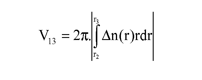
- volume integrals for the fiber of the invention, representing the volume V 11 of the central core, the volume V 12 of the intermediate cladding, and the volume V 13 of the trench.
- the term volume is not to be understood in a geometrical sense, but as a value taking account of three dimensions.
- V 11 2 ⁇ ⁇ ⁇ ⁇ 0 r 1 ⁇ n r ⁇ rdr
- V 12 2 ⁇ ⁇ . ⁇ r 1 r 2 ⁇ n r ⁇ rdr ⁇ ⁇ . r 2 2 - r 1 2 ⁇ ⁇ n 2
- V 13 2 ⁇ ⁇ . ⁇ r 2 r 3 ⁇ n r ⁇ rdr ⁇ ⁇ . r 3 2 - r 2 2 ⁇ ⁇ n 3
- Table 1 below gives the profile characteristics of eleven examples of profiles of fibers of the invention, designated ST1, ST3, ST4, ST6, ST7, ST10, ST11, ST13, ST14, ST15 for a step-index core profile, corresponding to that shown in Figure 1 , and AL2 for a graded-index or alpha-shape core profile, corresponding to that shown in Figure 2 .
- the table also gives the profile characteristics of six examples of fiber profiles that do not conform to the invention, i.e. that depart from the parameter compromise proposed by the invention.
- These profiles that correspond to fibers that do not conform to the invention are marked with an asterisk and designated ST2*, ST5*, ST8*, ST9*, ST12* for the fiber profiles that do not conform to the invention having a step-index profile and AL1* for the fiber profile that does not conform to the invention having a graded-index profile.
- the parameter values that depart from the compromise proposed by the invention are shown in bold.
- the first column of table I lists the examples.
- the second column gives the value of alpha if the central core has an alpha-shaped profile (graded-index profile).
- the next three columns give the corresponding values of the index differences ⁇ n 1 , ⁇ n 2 , ⁇ n 3 relative to the exterior optical cladding.
- the index difference values in the table are multiplied by 1000.
- the index values are measured at a wavelength of 633 nm.
- the profile examples ST2* and ST5* do not have a trench and the columns giving the values of r 3 , ⁇ n 3 , and r 3 -r 2 are not filled in for ST2* and ST5*.
- Table II below gives the propagation characteristics for examples of profiles in fibers that conform to the invention and, by way of comparison, the same profiles in fibers that do not conform to the invention.
- parameter values in Table II that depart from the compromise proposed by the invention are shown in bold.
- the first column of table II lists the examples.
- the next two columns respectively give the chromatic dispersion in ps/nm/km at a wavelength of 1550 nm and the chromatic dispersion slope in ps/(nm 2 .km) at a wavelength of 1550 nm.
- the next column gives of the mode field diameter (MFD) in ⁇ m at a wavelength of 1550 nm.
- the next column gives the effective area Aeff in ⁇ m 2 at a wavelength of 1550 nm.
- the next column gives the in-cable cut-off wavelength ⁇ cc in nm.
- Example Dispersion Slope MFD Aeff ⁇ cc at at at 1550 nm at 1550 nm 1550 nm 1550 nm (ps/nm/km) (ps/(nm 2 .km)) ( ⁇ m) ( ⁇ m 2 ) (nm) ST1 21.8 0.065 13.5 155 1462 ST2* 20.4 0.063 13.7 155 1440 ST3 21.5 0.065 13.8 160 1498 ST4 21.7 0.065 15.1 200 1760 ST5* 20 8 0.063 15.4 200 1501 ST6 21.6 0.065 14.1 170 1579 ST7 21 6 0.065 14.5 180 1525 ST8* 21.5 0.064 14.5 180 1461 ST9* 21.7 0.065 14.5 180 >2000 ST10 21.8 0.065 16.4 240 1843 ST11 20.5 0.064 14.3 167 1545 ST12* 22.1 0.064 13.8 167 1435 ST13 20.9 0.064 13.5 152 1547 ST14 21.3 0.066 13.6
- V 13 2 ⁇ ⁇ . ⁇ r 2 r 3 ⁇ n r ⁇ rdr
- the fibers of the eight examples that conform to the invention have an effective area greater than 150 ⁇ m 2 , a chromatic dispersion less than 22 ps/nm/km, a chromatic dispersion slope less than 0.07 ps/(nm 2 .km), macrobending losses for a bend radius of 10 mm less than 5 dB/m and 10 dB/m at wavelengths of 1550 nm and 1625 nm, respectively, and macrobending losses for a bend radius of 30 mm less than 0.05 dB per 100 turns at a wavelength of 1625 nm.
- the optimized trench volume that minimizes the in-cable cut-off wavelength ⁇ cc while preserving the above-mentioned performance in terms of bending losses is situated just above the solid line curve labeled "Trench minimum volume" in Figure 3 .
- the fibers of the invention are well suited to use in long-haul terrestrial or undersea optical systems. They preferably have microbending losses at a wavelength of 1550 nm less than 20 dB/km as measured by the TR62221 test method standardized by the IEC (Method B: Fixed Diameter Drum).
Landscapes
- Physics & Mathematics (AREA)
- General Physics & Mathematics (AREA)
- Optics & Photonics (AREA)
- Manufacture, Treatment Of Glass Fibers (AREA)
- Optical Fibers, Optical Fiber Cores, And Optical Fiber Bundles (AREA)
- Glass Compositions (AREA)
- Optical Communication System (AREA)
Abstract
Description
- The present invention relates to the field of optical fiber transmission and more specifically to an optical fiber having an enlarged effective area without this increasing its bending losses.
- Generally speaking, in the field of optical fibers the effective area concept was introduced for calculating non-linear effects. It usually corresponds to the usable section of an optical fiber, defined on the basis of the modal distribution of the field propagating in the fiber.
- By way of non-limiting example, the effective area Aeff is defined as follows:

- Moreover, the refractive index of an optical fiber is generally qualified as a function of the shape of the graph of the refractive index as a function of the radius of the fiber. It is conventional to represent the distance r to the center of the fiber along the abscissa axis and the difference between the refractive index at the distance r and the refractive index of the outer cladding of the fiber up the ordinate axis. The outer cladding providing optical cladding has a substantially constant refractive index; this optical cladding generally consists of pure silica but may also contain one or more doping agents. Thus refractive index profiles are described as step-shape profiles, trapezium-shape profiles, parabola-shape profiles (also known as alpha-shape profiles and graded-index profiles) or triangular-shape profiles where the graphs have the shape of a step, a trapezium, a parabola or a triangle, respectively. These curves generally represent the theoretical or setpoint profile of the fiber, as in practice fiber fabrication constraints can yield a slightly different profile.
- An optical fiber conventionally consists of an optical core for transmitting and possibly amplifying an optical signal and an optical cladding, also called the outer cladding, for confining the optical signal within the core. To this end, the refractive indices nc of the core and ng of the cladding are such that nc > ng. As is well known in the art, an optical signal propagates in a monomode optical fiber in a fundamental mode (LP01 mode) guided in the core and in guided secondary modes, called cladding modes, at a certain distance in the core-cladding assembly.
- The core may consist of a plurality of zones, including:
- · a central part or central core that has a radius r1 and a refractive index n1 > ng; and
- · a plurality of other zones between the central core and the optical cladding that have respective radii ri and refractive indices ni < n1 that may be less than or greater than the refractive index ng of the optical cladding.
- A zone between the central core and the optical cladding with a refractive index close to the index ng of the optical cladding is sometimes referred to as the internal cladding and a zone with a refractive index lower than the index ng of the optical cladding is sometimes referred to as the buried cladding or trench.
- Step-index fibers, also known as single-mode fibers (SMF), are conventionally used as line fibers in optical fiber transmission systems. These fibers present chromatic dispersion and chromatic dispersion slope that meet specific telecommunication standards and standardized cut-off wavelength and effective area values.
- The in-cable cut-off wavelength, as defined by subcommittee 86A of the International Electrotechnical Commission in IEC Standard 60793-1-44, is the wavelength at which the optical signal is no longer propagating as a monomode signal after propagating over 22 meters of fiber. The secondary mode most resistant to bending losses is usually the LP11 mode. The in-cable cut-off wavelength is therefore the wavelength from which the LP11 mode is sufficiently attenuated after propagating over 22 meters of fiber. The method proposed by the above standard amounts to considering the optical signal as a monomode signal if the attenuation of the LP11 mode is greater than or equal to 19.3 decibels (dB). According to the recommendations of IEC subcommittee 86A set out in the IEC Standard 6793-1-44, the in-cable cut-off wavelength is determined by imposing on the fiber two loops of 40 millimeters (mm) radius and placing the rest of the fiber (21.5 meters (m) of fiber) on a 140 mm radius drum.
- The effective fiber cut-off wavelength is also defined in IEC Standard 60793-1-44 and is the wavelength at which the attenuation of the LP11 mode is greater than or equal to 19.3 dB for 2 m of fiber packaged on a 140 mm radius drum.
- Terrestrial transmission systems typically use standard single-mode fibers (SSMF) having positive dispersion, an effective area Aeff up to about 80 square micrometers (µm2), and an attenuation of about 0.19 decibels per kilometer (dB/km).
- Undersea transmission systems employing repeaters use hybrid transmission lines with fibers having a positive dispersion, a large effective area (about 100 µm2 to 110 µm2) and a low attenuation (0.17 dB/km to 0.19 dB/km) and fibers having negative dispersion.
- Repeaterless undersea transmission systems typically use transmission lines comprising combinations of fibers having a positive dispersion (pure silica core fibers having an effective area in the
range 80 µm2 to 110 µm2). Record-breaking results in terms of capacity relative to distance have recently been obtained in the laboratory with fibers having an effective area of about 120 µm2 using coherent detection and sophisticated modulation formats. - As known in the art, increasing the effective area of a transmission fiber helps to reduce harmful non-linear effects in the fiber. A transmission fiber having a large effective area enables transmission over a greater distance and/or an increase in the operating margins of the transmission system.
- However, an effective area Aeff of about 130 µm2 at present represents the maximum limit likely to be obtained if it is also intended to guarantee a low level of bending losses and an in-cable cut-off wavelength λcc less than 1450 nanometers (nm), for example, and to ensure that the chromatic dispersion and the chromatic dispersion slope can be processed either by compensation modules or by coherent detection and sophisticated modulation formats.
- Thus the problem that arises is to increase the effective area Aeff beyond 150 µm2 without significantly increasing fabrication cost and without penalizing performance from the point of view of bending losses.
- A secondary aim is to maintain the chromatic dispersion and the chromatic dispersion slope at values respectively less than 22 picoseconds per nanometer per kilometer (ps/nm/km) and 0.07 picoseconds per square nanometer-kilometer (ps/(nm2.km)) and to guarantee monomode transmission over the extended C band [1530 nm-1569 nm].
- To increase the effective area of monomode fibers, step-index fiber profiles are usually employed in either constant cladding or buried cladding configurations.
- Document
US-A-6 658 190 describes profiles of this kind that have an effective area Aeff greater than 100 µm2. - However, the examples described in Document
US-A-6 658 190 are not optimized either in terms of bending losses or in terms of fabrication cost. Sample 5 described in DocumentUS-A-6 658 190 has a single-mode fiber profile with constant cladding and an effective area of 155 µm2, but its macrobending and microbending losses are unsatisfactory. Samples 6, 7, and 8 using step-index fiber and buried-cladding profiles have effective areas greater than 150 µm2 but the outside radius of the buried cladding is very large (greater than 29 micrometers (µm)), which penalizes fabrication cost. - Document
US-A-7 076 139 describes step-index and buried cladding optical fibers for which Δn1 < 4.4×10⁻³ and Aeff ≥ 120 µm2. - However, none of the examples described in Document
US-A-7 076 139 uses a fiber profile making it possible to combine an increased effective area, low bending losses, and a low buried cladding outside radius. Table 2 in DocumentUS-A-7 076 139 undoubtedly shows an example with Aeff = 156 µm2 but the outside radius of the buried cladding is too large (approximately 31 µm), which implies a high fabrication cost. - Document
US-A-6 483 975 describes fiber profiles consisting of a central core, intermediate cladding, and buried cladding having an effective area Aeff greater than 100 µm2. - However, the radius of the central core is too small (less than 6.4 µm) and the buried cladding is too large (greater than 15 µm) and insufficiently deep (depth above -2.9×10⁻³) to make it possible to obtain both an effective area greater than 150 µm2 and satisfactory bending losses. Also, the outside radius of the buried cladding is very large, which implies a high fabrication cost.
- Document
EP-A-1 477 831 describes in particular fiber profiles comprising a central core, an intermediate cladding, and a buried cladding, and having an effective area Aeff greater than 95 µm2 (in one example Aeff = 171 µm2) and an in-cable cut-off wavelength λcc less than or equal to 1310 nm. - However, with such values of λcc, it is not possible to have both an effective area Aeff greater than or equal to 150 µm2 and good performance in terms of bending losses. Moreover, the outside diameter of the buried cladding is very large (greater than 33 µm), which greatly increases fabrication cost.
- Document
US-A-7 254 305 describes fiber profiles comprising a central core, an intermediate cladding, and a buried cladding, and having a chromatic dispersion slope less than 0.07 ps/nm2/km and attenuation less than 0.20 dB/km. - The maximum value of the effective area Aeff disclosed in Document
USA-7 254 305 for an in-cable cut-off wavelength λcc of 1854 nm is 106 µm2. - However, for the profiles described in Document
US-A-7 254 305 , the values of Δn1, i.e. the index difference between the central core and the outer cladding (greater than 4.3×10⁻³) and Δn3, i.e. the index difference between the trench and the outer cladding (greater than -4.3×10⁻³), are too high to make it possible to obtain both an effective area greater than 150 µm2 and satisfactory bending losses. - Document
EP-A-1 978 383 describes fiber profiles comprising a central core, an intermediate cladding, and a buried cladding, and having an effective area Aeff greater than or equal to 120 µm2 and an effective fiber cut-off wavelength less than 1600 nm. - All the examples described in Document
EP-A-1 978 383 have central core index differences Δn1 greater than 3.9×10⁻³. However, with the above constraints on the cut-off wavelength and central core index, it is not possible to achieve an effective area greater than or equal to 150 µm2. The highest value of Aeff disclosed in DocumentEP-A-1 978 383 is only 135 µm2. - Document
WO-A-2008 137150 describes a fiber profile comprising a central core, an intermediate cladding, and a buried cladding, and having an effective area Aeff greater than 110 µm2, an in-cable cut-off wavelength λcc less than 1500 nm, and macrobending losses less than 0.7 decibels per turn (dB/turn) for a bend radius of 10 mm at a wavelength of 1550 nm. - However, such constraints on λcc and/or bending losses do not make it possible to obtain an effective area greater than or equal to 150 µm2. Two examples with Aeff > 150 µm2 are given in Document
WO-A-2008 137150 : - · firstly, fiber 7, for which Aeff has the value 155 µm2 and the outside radius of the buried cladding is too large (approximately 27.5 µm), which leads to a high fabrication cost; and
- · secondly, fiber 8, for which Aeff has the value 167 µm2 and the outside radius of the buried cladding is 18.5 µm; however, the macrobending losses are not optimized (they are about 10 decibels per meter (dB/m) at a wavelength of 1550 nm and greater than 0.1 dB/100 turns for a bend radius of 30 mm at a wavelength of 1625 nm). Moreover, the volume of the trench (see below) is not optimized as a function of the dimensions of the central core.
- Thus the above-mentioned prior art proposes no satisfactory compromise as to the profile and/or propagation characteristics that would make it possible to obtain a trench optical fiber having a large effective area and relatively low macrobending and microbending losses without significantly increasing the fiber fabrication cost.
- The present invention aims to propose a better compromise than the prior art between parameters that contribute to the performance of the fiber.
- In particular the invention proposes using profiles comprising a central core, an intermediate cladding, a buried cladding, and optical cladding in which the core has a refractive index difference Δn1 relative to the optical cladding in the range 2.6×10⁻³ to 3.5×10⁻³ and a buried cladding outside radius less than 24 µm. It is also proposed relaxing the constraint on the in-cable cut-off wavelength λcc of buried cladding optical fibers, i.e. to tolerate an increase in the in-cable cut-off wavelength λcc, the value of λcc nevertheless remaining less than or equal to 2000 nm, in order to achieve for such fibers an effective area greater than or equal to 150 µm2 at a wavelength of 1550 nm.
- It is proposed in particular to optimize the position and dimensions of the trench to enable the above-mentioned limited relaxation of the constraint on λcc and to guarantee very low bending losses.
- It is furthermore proposed, for a wavelength of 1550 nm, to maintain the chromatic dispersion at a value in the range 14 ps/nm/km to 24 ps/nm/km, or even at a value less than 22 ps/nm/km, and to maintain the chromatic dispersion slope at a value less than 0.08 ps/(nm2.km), or even less than 0.070 ps/(nm2.km).
- To this end, the invention more particularly proposes a monomode optical fiber comprising, from the center toward the periphery, a central core, an intermediate cladding, a trench, and an optical cladding, wherein:
- · the central core has a radius r1 and a refractive index difference Δn1 relative to the optical cladding in the range 2.6×10⁻³ to 3.5×10⁻³;
- · the intermediate cladding has a radius r2 and a refractive index difference Δn2 relative to the optical cladding;
- · the trench has a radius r3 that is less than 24 µm and preferably in the range of 14 to 24 µm and has a refractive index difference Δn3 relative to the optical cladding that is in the range -15.0×10⁻³ to -4.5×10⁻³, the volume V13 of the trench, defined as follows:

- · the fiber having an effective area greater than or equal to 150 µm2 at a wavelength of 1550 nm.
- Thus the above index difference Δn1 makes it possible to achieve an effective area Aeff greater than or equal to 150 µm2 at a wavelength of 1550 nm, the above radius r3 makes it possible to reduce fabrication cost, and the above index difference Δn3 makes it possible to obtain satisfactory trench volumes, between a minimum volume that minimizes bending losses and a maximum volume that minimizes the in-cable cut-off wavelength.
- In one particular embodiment, the volume V13 of the trench as a function of the volume V11 of the central core, defined as follows, where V11 and V13 are expressed in %.µm2 :

- The fiber of the invention advantageously has macrobending losses less than 5 dB/m for a bend radius of 10 mm at a wavelength of 1550 nm.
- The fiber of the invention advantageously has macrobending losses less than 10 dB/m for a bend radius of 10 mm at a wavelength of 1625 nm.
- The fiber of the invention advantageously has macrobending losses less than 0.05 dB/100 turns for a 30 mm bend radius at a wavelength of 1625 nm.
- The above relation between the volume V13 of the trench and the volume V11 of the central core makes it possible to guarantee that macrobending losses do not exceed the values referred to above.
- In one particular embodiment, the radius (r1) of the central core is in the range 6.5 µm to 10 µm.
- This makes it possible to achieve an effective area Aeff greater than or equal to 150 µm2 at a wavelength of 1550 nm with the range of values of Δn1 referred to above.
- In particular embodiments, the difference r2-r1 between the radius (r2) of the intermediate cladding and the radius (r1) of the central core is in the range 2.0 to 10, or even in the range 3.5 to 10.
- In another embodiment the radius (r2) of the intermediate cladding ranges from 8.5 to 20.0 µm.
- Firstly, the above minimum values of r2-r1 make it possible to maintain the chromatic dispersion and the chromatic dispersion slope within the values referred to above. In contrast, the above maximum values of r2-r1 make it possible to limit the outside radius r3 of the trench and to guarantee that bending losses do not exceed the values referred to above.
- In one particular embodiment, the difference r3-r2 between the radius (r3) of the trench and the radius (r2) of the intermediate cladding is in the range 3 µm to 12 µm.
- This makes it possible to obtain a sufficiently large trench volume combined with a limited outside radius.
- Embodiments of the fiber of the invention have one or more of the following features:
- · the intermediate cladding has a refractive index difference (Δn2) relative to the optical cladding in the range -1 ×10⁻³ to +1×10⁻³;
- · the fiber has an in-cable cut-off wavelength less than or equal to 2000 nm, or even less than or equal to 1800 nm, or even less than or equal to 1600 nm;
- · the fiber has a mode field diameter (MFD) greater than or equal to 13 µm at a wavelength of 1550 nm;
- . the fiber has a chromatic dispersion in the range 14 ps/nm/km to 24 ps/nm/km or even in the range 14 ps/nm/km to 22 ps/nm/km at a wavelength of 1550 nm; and
- · the fiber has a chromatic dispersion slope less than 0.08 ps/(nm2.km) or even less than 0.070 ps/(nm2.km) at a wavelength of 1550 nm.
- Thus the optical fiber of the invention has lower bending losses and a smaller buried cladding outside radius than prior art fibers for comparable effective area, chromatic dispersion, chromatic dispersion slope, and fiber diameter.
- The present invention also proposes an optical system receiving at least one portion of fiber of the invention.
- Other features and advantages of the invention become apparent on reading the following description of particular embodiments of the invention given by way of non-limiting example and with reference to the appended drawings, in which:
-
Figure 1 is a graphical representation of the theoretical profile of an optical fiber of a first particular embodiment of the present invention; - ·
Figure 2 is a graphical representation of the theoretical profile of an optical fiber of a second particular embodiment of the present invention; and - ·
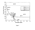
Figure 3 is a graph showing two curves respectively representing the minimum and maximum volumes of the trench of the profile of an optical fiber of the invention as a function of the volume of the fiber central core. - The present invention proposes increasing the effective area Aeff of a monomode optical fiber beyond 150 µm2 by relaxing the constraint on the in-cable cut-off wavelength λcc, i.e. by allowing λcc to exceed 1450 nm.
- To this end, the invention proposes using buried cladding fiber profiles.
- Thus the fiber of the invention has a central core, an intermediate cladding, and a buried cladding or trench. The central core, the intermediate cladding and the buried cladding are typically produced inside a silica tube by chemical vapor deposition (CVD). The exterior optical cladding consists of the tube and the overcladding of the tube, which is generally natural or doped silica, but may equally be produced by any other deposition technique (vapor axial deposition (VAD), or outside vapor deposition (OVD)).
- For example, the buried cladding may be obtained by plasma chemical vapor deposition (PCVD), making it possible to incorporate a large quantity of fluorine (or any other doping agent making it possible to reduce the refractive index compared to that of silica) to form a deeply buried cladding. Producing the buried cladding by incorporating microholes or microbubbles rather than by doping may equally be envisaged. However, for industrial fabrication doping is generally easier to control than incorporating microbubbles.
- The profile of the central core of the fiber of the invention may be a step-index, trapezoidal, or graded-index profile; these profile examples do not limit the scope of the invention.
- The position and volume of the buried cladding or trench may be optimized as a function of the dimensions of the central core in order:
- · to minimize bending losses;
- · to minimize the outside radius of the buried cladding in order not to increase fabrication cost significantly; and
- · possibly to maintain the in-cable cut-off wavelength λcc at a value less than or equal to 2000 nm.
- The volume of the trench is advantageously chosen to be both:
- · sufficiently large to make it possible to obtain very low macrobending losses, namely losses less than 5 dB/m for a bend radius of 10 mm at a wavelength of 1550 nm, less than 10 dB/m for a bend radius of 10 mm at a wavelength of 1625 nm, and less than 0.05 dB/100 turns for a bend radius of 30 mm at a wavelength of 1625 nm; and
- · sufficiently small to minimize the in-cable cut-off wavelength λcc for a given effective area Aeff.
- The position of the trench is furthermore advantageously chosen so as to be both:
- · sufficiently close to the central core to minimize the outside radius of the buried cladding and microbending losses; and
- · sufficiently far from the core to maintain the chromatic dispersion in the range 14 ps/nm/km to 24 ps/nm/km and the chromatic dispersion slope below 0.08 ps/(nm2.km) or, which is even more advantageous, to maintain the chromatic dispersion in the range 14 ps/nm/km to 22 ps/nm/km and the chromatic dispersion slope below 0.07 ps/(nm2.km).
-
Figure 1 shows a refractive index profile for a transmission fiber of a first particular embodiment of the invention with a step-index profile (i.e. a stepped central core). -
Figure 2 shows a refractive index profile for a transmission fiber of second particular embodiment of the invention with a graded-index fiber profile (i.e. an alpha-shaped central core, also known as a parabolic core). - Note that these two embodiments are merely non-limiting examples. In fact, the central core may equally well have a trapezoidal shape (for example).
- The profiles shown are theoretical profiles and the fiber actually obtained by drawing a preform may have a slightly different profile.
- As known in the art, an optical fiber is obtained by drawing a preform. The preform may for example consist of a glass (pure silica) tube of very high quality that forms part of the final exterior optical cladding and surrounds the central core and internal claddings of the fiber; this tube may thereafter be overcladded to increase its diameter before drawing it on a fiber-drawing tower. To fabricate the preform the tube is generally mounted horizontally in a glassmaking tower and retained at its two ends by glass rods; the tube is then rotated and heated locally to deposit components that determine the composition of the preform. This composition determines the optical characteristics of the finished fiber.
- The fiber of the invention has a central core having an index difference Δn1 relative to outer cladding providing optical cladding (the value of which index difference may either be substantially constant or depend on the distance r relative to the center of the fiber, according to whether the core has a step-index or graded-index profile, respectively), an intermediate cladding having an index difference Δn2 relative the outer cladding (which index difference is constant and possibly negative), and buried cladding or trench having a constant negative index difference Δn3 relative to the outer cladding. Note that throughout the description the expression index difference includes an index difference value of zero.
- The refractive indices in the intermediate cladding and the trench are substantially constant over their entire length. In the
Figure 1 embodiment the refractive index in the central core is substantially constant and in theFigure 2 embodiment the refractive index varies along a parabolic curve, decreasing from the center toward the exterior of the fiber. The width of the core is defined by its radius r1 and the widths of the intermediate cladding and the buried cladding are defined by their respective exterior radii r2 and r3. - It is seen in
Figure 2 that the index difference is Δn1 at the center of the core, i.e. for r = 0, and the index difference is Δn2 at the outside of the core, i.e. for r = r1. - The reference value generally adopted to define a theoretical index profile for an optical fiber is the index value of the outer cladding. The index values of the central core, the intermediate cladding, and the trench are then presented as index differences Δn1,2,3. The outer cladding generally consists of doped or undoped silica.
- Each section of the fiber profile may thus be defined by integrals that link the index variation and the radius of each section of the fiber.
- It is thus possible to define three volume integrals for the fiber of the invention, representing the volume V11 of the central core, the volume V12 of the intermediate cladding, and the volume V13 of the trench. The term volume is not to be understood in a geometrical sense, but as a value taking account of three dimensions. These three volume integrals may be expressed as follows:



- Table 1 below gives the profile characteristics of eleven examples of profiles of fibers of the invention, designated ST1, ST3, ST4, ST6, ST7, ST10, ST11, ST13, ST14, ST15 for a step-index core profile, corresponding to that shown in
Figure 1 , and AL2 for a graded-index or alpha-shape core profile, corresponding to that shown inFigure 2 . - By way of comparison, the table also gives the profile characteristics of six examples of fiber profiles that do not conform to the invention, i.e. that depart from the parameter compromise proposed by the invention. These profiles that correspond to fibers that do not conform to the invention are marked with an asterisk and designated ST2*, ST5*, ST8*, ST9*, ST12* for the fiber profiles that do not conform to the invention having a step-index profile and AL1* for the fiber profile that does not conform to the invention having a graded-index profile. The parameter values that depart from the compromise proposed by the invention are shown in bold.
- The values in the tables correspond to theoretical fiber profiles.
- The first column of table I lists the examples.
- The second column gives the value of alpha if the central core has an alpha-shaped profile (graded-index profile).
- The next three columns give the values in µm of the radii of the central core (r1), the intermediate cladding (r2), and where applicable the trench (r3).
- The next three columns give the corresponding values of the index differences Δn1, Δn2, Δn3 relative to the exterior optical cladding. The index difference values in the table are multiplied by 1000. The index values are measured at a wavelength of 633 nm.
- The next two columns give the values in µm of the radii difference r2-r1 and r3-r2.
- The profile examples ST2* and ST5* do not have a trench and the columns giving the values of r3, Δn3, and r3-r2 are not filled in for ST2* and ST5*.
- The last three columns of table I (which appear below the previous columns) respectively give the volume of the central core, the volume of the trench, and the minimum volume of the trench (see equation (1) below) needed to achieve the required bending characteristics. These three series of volumes are expressed in %.µm2 .
- Although the profile examples ST2* and ST5* have no trench (the volume of the trench is therefore zero for these examples), indicative theoretical values of the minimum volume of the trench that would be needed to achieve the required bending characteristics are given anyway, exclusively for the purpose of comparison with the profiles of fibers conforming to the invention.
Example alpha r 1 r 2 r 3 Δn1 at 633 nm Δn2 at 633 nm Δn3 at 633 nm r2-r1 r3-r2 (µm) (µm) (µm) (×103) (×103) (×103) (µm) (µm) ST1 - 7 15 10.81 16.40 2.9 -0 2 -7.7 '3.7 5.6 ST2' - 7 13 16.74 3.5 -0 2 - 9.6 ST3 - 7.23 11.72 17.58 3.1 -02 -6 7 4.4 5.9 ST4 - 8.76 12.74 16.81 3.3 -0 2 -6 7 4.0 4.1 ST5* - 8.41 16.94 3 0 -0 2 - 8.5 ST6 - 7.67 11 78 17.62 3 0 -0 2 -6.7 4 1 5.8 ST7 - 7.90 11.74 17 21 2 8 -0 2 -5.7 3.8 5.5 ST8* - 7.90 11 94 14.41 2 8 -0 2 -6.7 40 2.5 ST9* - 7.90 11.74 25.74 2.8 -0 2 -5.7 3.8 14.0 ST10 - 9 84 13.41 18.47 2.9 -0 2 -6.7 3.6 5.1 ST11 - 7.28 15.74 19.60 3 1 -0 2 -6 7 8.5 3.9 ST12* - 7.90 9 94 14.41 2.8 -0.2 -57 2.0 4.5 ST13 - 7.06 13.20 16.30 3.5 -02 -8 0 6.1 3.1 ST14 - 6.55 12 24 17 50 2.7 -0 2 -14.9 57 5.3 ST15 - 7.90 16 90 22.37 2 8 -0 2 -4.6 9 0 5.5 AL1* 10 7.00 13.60 18 70 2.8 0.0 -6.8 6.6 5.1 AL2 10 7.00 12.00 17.10 2.8 0.0 -13.0 5.0 5.1 Example Core volume Trench volume Trench minimum volume (%.µm2) (% µm2) (%µm2) ST1 47 358 265 ST2* 56 - 203 ST3 51 352 226 ST4 78 244 172 ST5* 68 - 178 ST6 56 352 201 ST7 55 275 204 ST8* 55 134 204 ST9* 55 912 204 ST10 89 329 171 ST11 51 279 226 ST12* 55 189 204 ST13 54 224 210 ST14 36 722 508 ST15 55 297 204 AL1* 36 352 517 AL2 36 606 517 - Table I: profile characteristics
- Table II below gives the propagation characteristics for examples of profiles in fibers that conform to the invention and, by way of comparison, the same profiles in fibers that do not conform to the invention. As in table I, parameter values in Table II that depart from the compromise proposed by the invention are shown in bold.
- The first column of table II lists the examples.
- The next two columns respectively give the chromatic dispersion in ps/nm/km at a wavelength of 1550 nm and the chromatic dispersion slope in ps/(nm2.km) at a wavelength of 1550 nm.
- The next column gives of the mode field diameter (MFD) in µm at a wavelength of 1550 nm.
- The next column gives the effective area Aeff in µm2 at a wavelength of 1550 nm.
- The next column gives the in-cable cut-off wavelength λcc in nm.
- The last three columns of table II appear below the previous columns and give:
· the macrobending losses in dB/m for a bend radius of 10 mm, respectively at a wavelength of 1550 nm and at a wavelength of 1625 nm; and
· the macrobending losses in dB/100 turns for a bend radius of 30 mm at a wavelength of 1625 nm.Example Dispersion Slope MFD Aeff λcc at at at 1550 nm at 1550 nm 1550 nm 1550 nm (ps/nm/km) (ps/(nm2.km)) (µm) (µm2) (nm) ST1 21.8 0.065 13.5 155 1462 ST2* 20.4 0.063 13.7 155 1440 ST3 21.5 0.065 13.8 160 1498 ST4 21.7 0.065 15.1 200 1760 ST5* 20 8 0.063 15.4 200 1501 ST6 21.6 0.065 14.1 170 1579 ST7 21 6 0.065 14.5 180 1525 ST8* 21.5 0.064 14.5 180 1461 ST9* 21.7 0.065 14.5 180 >2000 ST10 21.8 0.065 16.4 240 1843 ST11 20.5 0.064 14.3 167 1545 ST12* 22.1 0.064 13.8 167 1435 ST13 20.9 0.064 13.5 152 1547 ST14 21.3 0.066 13.6 151 1591 ST15 20.7 0.064 15.2 189 1596 AL1* 20.2 0.065 14.0 156 1380 AL2 20.5 0.065 13.9 154 1552 Example Macro-bending losses at 1550 nm R = 10 mm Macro-bending losses at 1625 nm R = 10 mm Macro-bending losses at 1625 nm R = 30 mm (dB/100 (dB/m) (dB/m) turns) ST1 1.0 1.9 ≤0.03 ST2* 36 64 ≤0.01 ST3 0.7 1.2 ≤0.01 ST4 1.3 2.4 <10-4 ST5* 108 163 ≤0.02 ST6 07 1.2 ≤0.01 ST7 2.6 4.4 ≤0.02 ST8* 25 38 ≥0.1 ST9* <10-2 <10-2 <10-3 ST10 1.1 2.0 <10-3 ST11 1.8 3.2 ≤0.01 ST12* 11 18 ≥0.1 ST13 1 6 3.1 <10-3 ST14 0.1 0.2 ≤0.04 ST15 1.7 3.1 ≤0.02 AL1* 24 4.1 ≥0.3 AL2 0.2 0.3 ≤0.04 - Table II: propagation characteristics
- The volume V11 of the core is defined as follows:

- The volume V13 of the trench is defined as follows:

- Accordingly, in the particular embodiments of
Figures 1 and 2 , in which the trench has a step-index profile, the volume of the trench is written as follows:
- Note that the fibers of the eight examples that conform to the invention have an effective area greater than 150 µm2, a chromatic dispersion less than 22 ps/nm/km, a chromatic dispersion slope less than 0.07 ps/(nm2.km), macrobending losses for a bend radius of 10 mm less than 5 dB/m and 10 dB/m at wavelengths of 1550 nm and 1625 nm, respectively, and macrobending losses for a bend radius of 30 mm less than 0.05 dB per 100 turns at a wavelength of 1625 nm.
- Many simulations have shown that to prevent the in-cable cut-off wavelength λcc exceeding 2000 nm it is preferable to choose trench volume less than 830%.µm2.
- These simulations have nevertheless also shown that it is preferable to choose trench volume sufficiently large to guarantee an acceptable level of bending losses.
- The smaller the volume of the central core, the greater must be the volume of the trench. For a bend radius of 10 mm macrobending losses less than 5 dB/m and 10 dB/m are guaranteed at wavelengths of 1550 nm and 1625 nm, respectively, and for a bend radius of 30 mm macrobending losses less than 0.05 dB per 100 turns are guaranteed at a wavelength of 1625 nm if the volume V13 (or Vtrench) of the trench as a function of the volume V11 (or Vcore) of the central core satisfies the following equation, in which the volumes of the trench and the core are expressed in %.µm2


- For a given central core volume, the optimized trench volume that minimizes the in-cable cut-off wavelength λcc while preserving the above-mentioned performance in terms of bending losses is situated just above the solid line curve labeled "Trench minimum volume" in
Figure 3 . - Note that:
- · The fibers of examples ST2* and ST5* have profiles including a step-index central core, a cladding (internal cladding) that is not deeply buried, and an optical cladding. In other words, they have no trench. These two profiles have the same effective area Aeff as the intermediate cladding and trench profiles of examples ST1 and ST4, respectively. With Aeff = 155 µm2 and λcc of the same order of magnitude, compared to example ST2*, example ST1 makes it possible to reduce macrobending losses by a factor of more than 30 for a bend radius R = 10 mm, maintaining macrobending losses for a bend radius R = 30 mm at a sufficiently low level without degrading performance in terms of microbending losses. By relaxing the constraint on λcc, i.e. by accepting λcc exceeding 1700 nm, compared to example ST5*, example ST4 makes it possible to reduce macrobending losses for a bend radius R = 10 mm from approximately 100 dB/m to less than 5 dB/m at wavelengths of 1550 nm and 1625 nm, which cannot be achieved with internal cladding configurations that are not deeply buried if Aeff is of the order of 200 µm2. Furthermore, performance in terms of microbending losses is not degraded.
- · The fibers of examples ST8* and ST9* have profiles with an intermediate cladding and a trench having the same effective area as the fiber of example ST7. However, the position and volume of the trench are not optimized. The volume of the trench in example ST8* is too small given the volume of the central core in the same example and consequently in example ST8* the macrobending losses for bend radii of 10 mm and 30 mm are too high. Conversely, the volume of the trench in example ST9* is too large and consequently the value of λcc is too high and the outside radius of the trench is too large, which penalizes fabrication cost.
- · Example ST12* is close to the limit (the point representing this example on the
Figure 3 graph is under the curve labeled "Trench minimum volume" but very close to it), but is not optimized in terms of trench volume. Compared to example ST11, which has the same value of Aeff, the volume of the trench of example ST12* is too small and as a result the macrobending losses for bend radii of 10 mm and 30 mm are too high. - · The fiber of example AL1* has a profile very close to the "Fiber 8" example in Document
WO-A-2008 137150 referred to in the introductory portion of this description. Once again, the volume of the trench is not optimized here as a function of the volume of the central core and, as a result, the macrobending losses for a bend radius of 30 mm are too high. In contrast, the fiber of example AL2, which conforms to the present invention, has the same core as example AL1* but the dimensions of the trench in example AL2 are optimized in order to achieve a good compromise between bending losses and in-cable cut-off wavelength. - The fibers of the invention are well suited to use in long-haul terrestrial or undersea optical systems. They preferably have microbending losses at a wavelength of 1550 nm less than 20 dB/km as measured by the TR62221 test method standardized by the IEC (Method B: Fixed Diameter Drum).
Claims (14)
- A monomode optical fiber comprising, from the center toward the periphery, a central core, an intermediate cladding, a trench, and an optical cladding, wherein:· the central core has a radius r1 and a refractive index difference Δn1 relative to the optical cladding in the range 2.6×10⁻³ to 3.5×10⁻³;· the intermediate cladding has a radius r2 and a refractive index difference Δn2 relative to the optical cladding;· the trench has a radius r3 that is less than 24 µm and a refractive index difference Δn3 relative to the optical cladding that is in the range -15.0×10⁻³ to -4.5×10⁻³, the volume V13 of the trench, defined as follows:
 · the fiber having an effective area greater than or equal to 150 µm2 at a wavelength of 1550 nm.
 - A fiber according to claim 1, wherein the volume V13 of the trench as a function of the volume V11 of the central core, defined as follows, where V11 and V13 are expressed in %.µm2:

- A fiber according to claim 2, having macrobending losses less than 5 dB/m for a bend radius of 10 mm at a wavelength of 1550 nm.
- A fiber according to claim 2 or claim 3, having macrobending losses less than 10 dB/m for a bend radius of 10 mm at a wavelength of 1625 nm.
- A fiber according to claim 2, 3 or 4, having macrobending losses less than 0.05 dB/100 turns for a 30 mm bend radius at a wavelength of 1625 nm.
- A fiber according to any preceding claim, wherein the radius (r1) of the central core is in the range 6.5 µm to 10 µm.
- A fiber according to any preceding claim, wherein the difference r2-r1 between the radius (r2) of the intermediate cladding and the radius (r1) of the central core is in the range 2.0 to 10, preferably in the range 3.5 to 10.
- A fiber according to any preceding claim, wherein the difference r3-r2 between the radius (r3) of the trench and the radius (r2) of the intermediate cladding is in the range 3 µm to 12 µm.
- A fiber according to any preceding claim, wherein the intermediate cladding has a refractive index difference (Δn2) relative to the optical cladding in the range -1 × 10⁻³ to + 1 × 10⁻³.
- A fiber according to any preceding claim, having an in-cable cut-off wavelength less than or equal to 2000 nm, preferably less than or equal to 1800 nm, more preferably less than or equal to 1600 nm.
- A fiber according to any preceding claim, having a mode field diameter (MFD) greater than or equal to 13 µm at a wavelength of 1550 nm.
- A fiber according to any preceding claim, having a chromatic dispersion in the range 14 ps/nm/km to 24 ps/nm/km at a wavelength of 1550 nm, preferably in the range 14 ps/nm/km to 22 ps/nm/km at a wavelength of 1550 nm.
- A fiber according to any preceding claim, having a chromatic dispersion slope less than 0.08 ps/(nm2.km) at a wavelength of 1550 nm, preferably less than 0.070 ps/(nm2.km) at a wavelength of 1550 nm.
- An optical system receiving at least one portion of fiber according to any one of claims 1 to 13.
Applications Claiming Priority (1)
| Application Number | Priority Date | Filing Date | Title |
|---|---|---|---|
| FR1055368A FR2962230B1 (en) | 2010-07-02 | 2010-07-02 | OPTICAL FIBER MONOMODE |
Publications (2)
| Publication Number | Publication Date |
|---|---|
| EP2402799A1 true EP2402799A1 (en) | 2012-01-04 |
| EP2402799B1 EP2402799B1 (en) | 2016-01-20 |
Family
ID=43638622
Family Applications (1)
| Application Number | Title | Priority Date | Filing Date |
|---|---|---|---|
| EP11169805.6A Active EP2402799B1 (en) | 2010-07-02 | 2011-06-14 | A monomode optical fiber |
Country Status (7)
| Country | Link |
|---|---|
| US (1) | US8867879B2 (en) |
| EP (1) | EP2402799B1 (en) |
| JP (1) | JP5804793B2 (en) |
| CN (1) | CN102313924B (en) |
| DK (1) | DK2402799T3 (en) |
| ES (1) | ES2564013T3 (en) |
| FR (1) | FR2962230B1 (en) |
Cited By (4)
| Publication number | Priority date | Publication date | Assignee | Title |
|---|---|---|---|---|
| EP2717077A1 (en) | 2012-10-02 | 2014-04-09 | Telekomunikacja Polska S.A. | Coaxial optical fiber with subwavelength core |
| US8867879B2 (en) | 2010-07-02 | 2014-10-21 | Draka Comteq, B.V. | Single-mode optical fiber |
| EP2706388A4 (en) * | 2012-02-14 | 2015-07-08 | Sumitomo Electric Industries | OPTICAL PROBE |
| CN112305665A (en) * | 2019-08-02 | 2021-02-02 | 斯特里特技术有限公司 | Cutoff Shift Fiber with Large Effective Area |
Families Citing this family (41)
| Publication number | Priority date | Publication date | Assignee | Title |
|---|---|---|---|---|
| WO2010077132A1 (en) | 2008-12-31 | 2010-07-08 | Draka Comteq B.V. | Uvled apparatus for curing glass-fiber coatings |
| US9014525B2 (en) | 2009-09-09 | 2015-04-21 | Draka Comteq, B.V. | Trench-assisted multimode optical fiber |
| US8682123B2 (en) | 2010-07-15 | 2014-03-25 | Draka Comteq, B.V. | Adhesively coupled optical fibers and enclosing tape |
| EP2418183B1 (en) | 2010-08-10 | 2018-07-25 | Draka Comteq B.V. | Method for curing coated glass fibres providing increased UVLED intensitiy |
| US8571369B2 (en) | 2010-09-03 | 2013-10-29 | Draka Comteq B.V. | Optical-fiber module having improved accessibility |
| FR2966256B1 (en) | 2010-10-18 | 2012-11-16 | Draka Comteq France | MULTIMODE OPTICAL FIBER INSENSITIVE TO LOSSES BY |
| US8824845B1 (en) | 2010-12-03 | 2014-09-02 | Draka Comteq, B.V. | Buffer tubes having reduced stress whitening |
| FR2971061B1 (en) | 2011-01-31 | 2013-02-08 | Draka Comteq France | BROAD BANDWIDTH OPTICAL FIBER WITH LOW CURB LOSSES |
| DK2482106T5 (en) | 2011-01-31 | 2014-09-22 | Draka Comteq Bv | Multi-mode fiber |
| PT2678728T (en) | 2011-02-21 | 2018-07-05 | Draka Comteq Bv | Fiber Optic Interconnect Cable |
| EP2495589A1 (en) | 2011-03-04 | 2012-09-05 | Draka Comteq B.V. | Rare earth doped amplifying optical fiber for compact devices and method of manufacturing thereof |
| EP2503368A1 (en) | 2011-03-24 | 2012-09-26 | Draka Comteq B.V. | Multimode optical fiber with improved bend resistance |
| EP2506044A1 (en) | 2011-03-29 | 2012-10-03 | Draka Comteq B.V. | Multimode optical fiber |
| EP2518546B1 (en) | 2011-04-27 | 2018-06-20 | Draka Comteq B.V. | High-bandwidth, radiation-resistant multimode optical fiber |
| ES2438173T3 (en) | 2011-05-27 | 2014-01-16 | Draka Comteq Bv | Single mode fiber optic |
| EP2533082B1 (en) | 2011-06-09 | 2013-12-25 | Draka Comteq BV | Single mode optical fiber |
| DK2541292T3 (en) * | 2011-07-01 | 2014-12-01 | Draka Comteq Bv | A multimode optical fiber |
| EP2584340A1 (en) | 2011-10-20 | 2013-04-24 | Draka Comteq BV | Hydrogen sensing fiber and hydrogen sensor |
| NL2007831C2 (en) | 2011-11-21 | 2013-05-23 | Draka Comteq Bv | Apparatus and method for carrying out a pcvd deposition process. |
| US8929701B2 (en) | 2012-02-15 | 2015-01-06 | Draka Comteq, B.V. | Loose-tube optical-fiber cable |
| WO2013160714A1 (en) | 2012-04-27 | 2013-10-31 | Draka Comteq Bv | Hybrid single and multimode optical fiber for a home network |
| CN102768383A (en) * | 2012-08-01 | 2012-11-07 | 长飞光纤光缆有限公司 | Single mode fiber with large effective area |
| CN102944910B (en) | 2012-10-30 | 2015-07-22 | 长飞光纤光缆股份有限公司 | Single-mode fiber with larger effective area |
| CN103257393B (en) * | 2012-10-30 | 2015-03-04 | 长飞光纤光缆股份有限公司 | Optical fiber large in effective area |
| US9002164B2 (en) | 2013-02-28 | 2015-04-07 | Fujikura Ltd. | Optical fiber and method of manufacturing the same |
| US9188754B1 (en) | 2013-03-15 | 2015-11-17 | Draka Comteq, B.V. | Method for manufacturing an optical-fiber buffer tube |
| NL2011075C2 (en) | 2013-07-01 | 2015-01-05 | Draka Comteq Bv | Pcvd process with removal of substrate tube. |
| CN105899982B (en) * | 2013-12-20 | 2019-11-22 | 德拉克通信科技公司 | Single-mode fiber with trapezoidal core exhibiting reduced loss |
| JP2017535804A (en) * | 2014-09-29 | 2017-11-30 | コーニング インコーポレイテッド | Quasi-single mode optical fiber with large effective area |
| JP2016075792A (en) * | 2014-10-07 | 2016-05-12 | 矢崎総業株式会社 | Multimode optical fiber |
| JP6658757B2 (en) | 2015-08-04 | 2020-03-04 | 住友電気工業株式会社 | Optical connection parts |
| JP6477890B2 (en) * | 2015-08-13 | 2019-03-06 | 住友電気工業株式会社 | Optical connection parts |
| PL3729151T3 (en) | 2017-12-21 | 2022-07-25 | Draka Comteq France | Bending-loss insensitive single mode fibre, with a shallow trench, and corresponding optical system |
| JPWO2020162406A1 (en) * | 2019-02-05 | 2021-12-16 | 古河電気工業株式会社 | Optical fiber |
| US11473191B2 (en) * | 2019-02-27 | 2022-10-18 | Applied Materials, Inc. | Method for creating a dielectric filled nanostructured silica substrate for flat optical devices |
| CN112305666A (en) * | 2019-07-29 | 2021-02-02 | 斯特里特技术有限公司 | Cutoff Shift Fiber |
| JP6890638B2 (en) * | 2019-08-05 | 2021-06-18 | 京セラ株式会社 | Fiber optic power supply system and fiber optic cable |
| WO2021193260A1 (en) | 2020-03-27 | 2021-09-30 | 古河電気工業株式会社 | Optical fiber |
| CN114195379A (en) * | 2021-12-21 | 2022-03-18 | 通鼎互联信息股份有限公司 | Drawing method of low-loss cut-off wavelength displacement single-mode optical fiber |
| CN115793134B (en) * | 2022-10-14 | 2026-05-01 | 暨南大学 | Groove-assisted random coupling multi-core optical fiber |
| CN119322388A (en) * | 2024-10-22 | 2025-01-17 | 长飞光纤光缆股份有限公司 | Small-outer-diameter bending-resistant single-mode fiber |
Citations (11)
| Publication number | Priority date | Publication date | Assignee | Title |
|---|---|---|---|---|
| US6483975B1 (en) | 2001-04-27 | 2002-11-19 | Fitel Usa Corp. | Positive dispersion optical fiber having large effective area |
| US6658190B2 (en) | 1999-04-13 | 2003-12-02 | Sumitomo Electric Industries, Ltd. | Optical fiber and optical communication system including the same |
| EP1477831A1 (en) | 2003-05-12 | 2004-11-17 | FITEL USA CORPORATION (a Delaware Corporation) | Super-large-effective-area (SLA) optical fiber and communication system incorporating the same |
| US7076139B1 (en) | 1999-08-12 | 2006-07-11 | Fujikura Ltd. | Optical fiber and optical transmission system |
| US7254305B2 (en) | 2004-04-29 | 2007-08-07 | Corning Incorporated | Low attenuation large effective area optical fiber |
| EP1852721A1 (en) * | 2006-05-03 | 2007-11-07 | Draka Comteq B.V. | Chromatic dispersion compensating fiber |
| WO2008027351A2 (en) * | 2006-08-31 | 2008-03-06 | Corning Incorporated | Low bend loss single mode optical fiber |
| EP1978383A1 (en) | 2007-04-06 | 2008-10-08 | Draka Comteq B.V. | Transmission optical fiber having large effective area |
| WO2008137150A1 (en) | 2007-05-07 | 2008-11-13 | Corning Incorporated | Large effective area fiber |
| US20080279515A1 (en) * | 2007-05-07 | 2008-11-13 | Scott Robertson Bickham | Optical fiber containing alkali metal oxide |
| WO2009062131A1 (en) * | 2007-11-09 | 2009-05-14 | Draka Comteq, B.V. | Microbend- resistant optical fiber |
Family Cites Families (114)
| Publication number | Priority date | Publication date | Assignee | Title |
|---|---|---|---|---|
| US4838643A (en) | 1988-03-23 | 1989-06-13 | Alcatel Na, Inc. | Single mode bend insensitive fiber for use in fiber optic guidance applications |
| FR2647778B1 (en) | 1989-06-05 | 1992-11-20 | Comp Generale Electricite | METHOD AND DEVICE FOR EXTERNAL DEPOSITION BY HYDROXYLIC ION-FREE SILICA PLASMA |
| FR2713621B1 (en) | 1993-12-14 | 1996-01-05 | Alcatel Fibres Optiques | Method for plasma recharging of a preform for optical fiber and optical fiber originating from the preform recharged according to this method. |
| US5574816A (en) | 1995-01-24 | 1996-11-12 | Alcatel Na Cable Sytems, Inc. | Polypropylene-polyethylene copolymer buffer tubes for optical fiber cables and method for making the same |
| US5717805A (en) | 1996-06-12 | 1998-02-10 | Alcatel Na Cable Systems, Inc. | Stress concentrations in an optical fiber ribbon to facilitate separation of ribbon matrix material |
| US5781684A (en) * | 1996-12-20 | 1998-07-14 | Corning Incorporated | Single mode optical waveguide having large effective area |
| US7322122B2 (en) | 1997-01-15 | 2008-01-29 | Draka Comteq B.V. | Method and apparatus for curing a fiber having at least two fiber coating curing stages |
| FR2762836B1 (en) | 1997-05-02 | 1999-07-23 | Alsthom Cge Alcatel | PROCESS AND APPARATUS FOR MANUFACTURING FIBERGLASS PREFORMS |
| FR2760540B1 (en) | 1997-03-10 | 1999-04-16 | Alsthom Cge Alcatel | OPTICAL FIBER CABLE TIGHTENED IN SHEATH |
| US5911023A (en) | 1997-07-10 | 1999-06-08 | Alcatel Alsthom Compagnie Generale D'electricite | Polyolefin materials suitable for optical fiber cable components |
| US6269663B1 (en) | 1998-03-05 | 2001-08-07 | Alcatel | Method of purifying silica and depositing on an optical fiber preform |
| US6066397A (en) | 1998-03-31 | 2000-05-23 | Alcatel | Polypropylene filler rods for optical fiber communications cables |
| US6175677B1 (en) | 1998-04-17 | 2001-01-16 | Alcatel | Optical fiber multi-ribbon and method for making the same |
| US6085009A (en) | 1998-05-12 | 2000-07-04 | Alcatel | Water blocking gels compatible with polyolefin optical fiber cable buffer tubes and cables made therewith |
| US6215931B1 (en) | 1999-01-26 | 2001-04-10 | Alcatel | Flexible thermoplastic polyolefin elastomers for buffering transmission elements in a telecommunications cable |
| US6134363A (en) | 1999-02-18 | 2000-10-17 | Alcatel | Method for accessing optical fibers in the midspan region of an optical fiber cable |
| US6381390B1 (en) | 1999-04-06 | 2002-04-30 | Alcatel | Color-coded optical fiber ribbon and die for making the same |
| US6181857B1 (en) | 1999-05-12 | 2001-01-30 | Alcatel | Method for accessing optical fibers contained in a sheath |
| US6314224B1 (en) | 1999-06-18 | 2001-11-06 | Alcatel | Thick-walled cable jacket with non-circular cavity cross section |
| US6334016B1 (en) | 1999-06-30 | 2001-12-25 | Alcatel | Optical fiber ribbon matrix material having optimal handling characteristics |
| US6321012B1 (en) | 1999-08-30 | 2001-11-20 | Alcatel | Optical fiber having water swellable material for identifying grouping of fiber groups |
| US6493491B1 (en) | 1999-09-28 | 2002-12-10 | Alcatel | Optical drop cable for aerial installation |
| US6321014B1 (en) | 1999-11-01 | 2001-11-20 | Alcatel | Method for manufacturing optical fiber ribbon |
| FR2809499B1 (en) | 2000-05-29 | 2003-10-03 | Cit Alcatel | PROTECTIVE SKIN FOR OPTICAL FIBERS |
| US6603908B2 (en) | 2000-08-04 | 2003-08-05 | Alcatel | Buffer tube that results in easy access to and low attenuation of fibers disposed within buffer tube |
| US6618538B2 (en) | 2000-12-20 | 2003-09-09 | Alcatel | Method and apparatus to reduce variation of excess fiber length in buffer tubes of fiber optic cables |
| US6922515B2 (en) | 2000-12-20 | 2005-07-26 | Alcatel | Method and apparatus to reduce variation of excess fiber length in buffer tubes of fiber optic cables |
| US7346244B2 (en) | 2001-03-23 | 2008-03-18 | Draka Comteq B.V. | Coated central strength member for fiber optic cables with reduced shrinkage |
| NL1018338C2 (en) * | 2001-06-20 | 2002-12-30 | Draka Fibre Technology Bv | Optical fiber. |
| US7045010B2 (en) | 2001-09-06 | 2006-05-16 | Alcatel | Applicator for high-speed gel buffering of flextube optical fiber bundles |
| US6749446B2 (en) | 2001-10-10 | 2004-06-15 | Alcatel | Optical fiber cable with cushion members protecting optical fiber ribbon stack |
| US6912347B2 (en) | 2002-11-15 | 2005-06-28 | Alcatel | Optimized fiber optic cable suitable for microduct blown installation |
| US6941049B2 (en) | 2003-06-18 | 2005-09-06 | Alcatel | Fiber optic cable having no rigid strength members and a reduced coefficient of thermal expansion |
| EP1557707B1 (en) | 2004-01-26 | 2007-12-05 | Draka Comteq B.V. | Buffer tube coupling coil and method of installing a fiber optic cable |
| US7567739B2 (en) | 2007-01-31 | 2009-07-28 | Draka Comteq B.V. | Fiber optic cable having a water-swellable element |
| US7515795B2 (en) | 2005-07-20 | 2009-04-07 | Draka Comteq B.V. | Water-swellable tape, adhesive-backed for coupling when used inside a buffer tube |
| US7599589B2 (en) | 2005-07-20 | 2009-10-06 | Draka Comteq B.V. | Gel-free buffer tube with adhesively coupled optical element |
| US8135252B2 (en) | 2005-07-20 | 2012-03-13 | Draka Comteq B.V. | Grease-free buffer optical fiber buffer tube construction utilizing a water-swellable, texturized yarn |
| FR2893149B1 (en) | 2005-11-10 | 2008-01-11 | Draka Comteq France | OPTICAL FIBER MONOMODE. |
| FR2896795B1 (en) | 2006-01-27 | 2008-04-18 | Draka Compteq France | PROCESS FOR PRODUCING AN OPTICAL FIBER PREFORM |
| WO2007091879A1 (en) | 2006-02-08 | 2007-08-16 | Draka Comteq B.V. | Optical fiber cable suited for blown installation or pushing installation in microducts of small diameter |
| FR2899693B1 (en) | 2006-04-10 | 2008-08-22 | Draka Comteq France | OPTICAL FIBER MONOMODE. |
| NL1031792C2 (en) | 2006-05-11 | 2007-11-13 | Draka Comteq Bv | Cable assembly and method for installing such a cable assembly. |
| US7665902B2 (en) | 2006-05-11 | 2010-02-23 | Draka Comteq, B.V. | Modified pre-ferrulized communication cable assembly and installation method |
| FR2903501B1 (en) | 2006-07-04 | 2008-08-22 | Draka Comteq France Sa | DOPED OPTICAL FIBER WITH FLUORINE |
| FR2904876B1 (en) | 2006-08-08 | 2008-11-21 | Draka Comteq France | FIBER OPTIC TELECOMMUNICATION CABLE |
| FR2908250B1 (en) | 2006-11-03 | 2009-01-09 | Draka Comteq France Sa Sa | COMPENSATION FIBER OF CHROMATIC DISPERSION |
| FR2908525B1 (en) | 2006-11-10 | 2009-06-26 | Draka Comteq France Sa Sa | FIBER OPTIC TELECOMMUNICATION CABLE |
| US7526169B2 (en) * | 2006-11-29 | 2009-04-28 | Corning Incorporated | Low bend loss quasi-single-mode optical fiber and optical fiber line |
| EP1930753B1 (en) * | 2006-12-04 | 2015-02-18 | Draka Comteq B.V. | Optical fiber with high Brillouin threshold power and low bending losses |
| FR2915002B1 (en) | 2007-04-11 | 2009-11-06 | Draka Comteq France | METHOD FOR ACCESSING ONE OR MORE OPTICAL FIBERS OF A TELECOMMUNICATION CABLE |
| US7724998B2 (en) | 2007-06-28 | 2010-05-25 | Draka Comteq B.V. | Coupling composition for optical fiber cables |
| US7639915B2 (en) | 2007-06-28 | 2009-12-29 | Draka Comteq B.V. | Optical fiber cable having a deformable coupling element |
| US7646952B2 (en) | 2007-06-28 | 2010-01-12 | Draka Comteq B.V. | Optical fiber cable having raised coupling supports |
| FR2922657B1 (en) | 2007-10-23 | 2010-02-12 | Draka Comteq France | MULTIMODE FIBER. |
| US8600206B2 (en) | 2008-11-07 | 2013-12-03 | Draka Comteq, B.V. | Reduced-diameter optical fiber |
| US8031997B2 (en) | 2007-11-09 | 2011-10-04 | Draka Comteq, B.V. | Reduced-diameter, easy-access loose tube cable |
| US8145026B2 (en) | 2007-11-09 | 2012-03-27 | Draka Comteq, B.V. | Reduced-size flat drop cable |
| US8467650B2 (en) | 2007-11-09 | 2013-06-18 | Draka Comteq, B.V. | High-fiber-density optical-fiber cable |
| US8041168B2 (en) | 2007-11-09 | 2011-10-18 | Draka Comteq, B.V. | Reduced-diameter ribbon cables with high-performance optical fiber |
| US8041167B2 (en) | 2007-11-09 | 2011-10-18 | Draka Comteq, B.V. | Optical-fiber loose tube cables |
| US8165439B2 (en) | 2007-11-09 | 2012-04-24 | Draka Comteq, B.V. | ADSS cables with high-performance optical fiber |
| US8081853B2 (en) | 2007-11-09 | 2011-12-20 | Draka Comteq, B.V. | Single-fiber drop cables for MDU deployments |
| US20090214167A1 (en) | 2008-02-25 | 2009-08-27 | Draka Comteq B.V. | Optical Cable Buffer Tube with Integrated Hollow Channels |
| FR2929716B1 (en) | 2008-04-04 | 2011-09-16 | Draka Comteq France Sa | OPTICAL FIBER WITH DISPERSION OFFSET. |
| FR2930997B1 (en) | 2008-05-06 | 2010-08-13 | Draka Comteq France Sa | OPTICAL FIBER MONOMODE |
| FR2931253B1 (en) | 2008-05-16 | 2010-08-20 | Draka Comteq France Sa | FIBER OPTIC TELECOMMUNICATION CABLE |
| FR2932932B1 (en) | 2008-06-23 | 2010-08-13 | Draka Comteq France Sa | MULTIPLEX WAVE LENGTH OPTIC SYSTEM WITH MULTIMODE OPTIC FIBERS |
| FR2933779B1 (en) | 2008-07-08 | 2010-08-27 | Draka Comteq France | MULTIMODE OPTIC FIBERS |
| US8401353B2 (en) | 2008-09-12 | 2013-03-19 | Draka Comteq B.V. | Optical fiber cable assembly |
| US7974507B2 (en) | 2008-09-12 | 2011-07-05 | Draka Comteq, B.V. | High-fiber-density optical fiber cable |
| US7970247B2 (en) | 2008-09-12 | 2011-06-28 | Draka Comteq B.V. | Buffer tubes for mid-span storage |
| FR2938389B1 (en) | 2008-11-07 | 2011-04-15 | Draka Comteq France | MULTIMODE OPTICAL SYSTEM |
| DK2187486T3 (en) | 2008-11-12 | 2014-07-07 | Draka Comteq Bv | Reinforcing optical fiber and method of manufacture |
| US7676129B1 (en) * | 2008-11-18 | 2010-03-09 | Corning Incorporated | Bend-insensitive fiber with two-segment core |
| FR2939246B1 (en) | 2008-12-02 | 2010-12-24 | Draka Comteq France | AMPLIFIER OPTICAL FIBER AND METHOD OF MANUFACTURE |
| FR2939522B1 (en) | 2008-12-08 | 2011-02-11 | Draka Comteq France | OPTICAL FIBER AMPLIFIER RESISTANT TO IONIZING RADIATION |
| FR2939911B1 (en) | 2008-12-12 | 2011-04-08 | Draka Comteq France | SOLDERED OPTICAL FIBER, TELECOMMUNICATION CABLE COMPRISING MULTIPLE OPTICAL FIBERS AND METHOD FOR MANUFACTURING SUCH A FIBER |
| NL1036343C2 (en) | 2008-12-19 | 2010-06-22 | Draka Comteq Bv | METHOD AND APPARATUS FOR MANUFACTURING AN OPTICAL FORM. |
| EP2204681B1 (en) | 2008-12-30 | 2016-03-09 | Draka Comteq B.V. | Optical fibre cable comprising a perforated water-blocking element |
| WO2010077132A1 (en) | 2008-12-31 | 2010-07-08 | Draka Comteq B.V. | Uvled apparatus for curing glass-fiber coatings |
| FR2940839B1 (en) | 2009-01-08 | 2012-09-14 | Draka Comteq France | INDEX GRADIENT MULTIMODAL OPTICAL FIBER, METHODS FOR CHARACTERIZATION AND MANUFACTURE OF SUCH A FIBER |
| FR2941539B1 (en) | 2009-01-23 | 2011-02-25 | Draka Comteq France | OPTICAL FIBER MONOMODE |
| FR2941540B1 (en) | 2009-01-27 | 2011-05-06 | Draka Comteq France | MONOMODE OPTICAL FIBER HAVING ENHANCED EFFECTIVE SURFACE |
| FR2941541B1 (en) | 2009-01-27 | 2011-02-25 | Draka Comteq France | OPTICAL FIBER MONOMODE |
| US9360647B2 (en) | 2009-02-06 | 2016-06-07 | Draka Comteq, B.V. | Central-tube cable with high-conductivity conductors encapsulated with high-dielectric-strength insulation |
| FR2942571B1 (en) | 2009-02-20 | 2011-02-25 | Draka Comteq France | AMPLIFIER OPTICAL FIBER COMPRISING NANOSTRUCTURES |
| FR2942551B1 (en) | 2009-02-23 | 2011-07-15 | Draka Comteq France | CABLE COMPRISING ELEMENTS TO BE EXTRACTED, METHOD OF EXTRACTING THESE ELEMENTS AND METHOD OF MANUFACTURING THE SAME |
| FR2946436B1 (en) | 2009-06-05 | 2011-12-09 | Draka Comteq France | MULTIMODE OPTICAL FIBER WITH LARGE BANDWIDTH WITH AN OPTIMIZED HEAT-SLEEVE INTERFACE |
| US20110026889A1 (en) | 2009-07-31 | 2011-02-03 | Draka Comteq B.V. | Tight-Buffered Optical Fiber Unit Having Improved Accessibility |
| FR2953606B1 (en) | 2009-12-03 | 2012-04-27 | Draka Comteq France | MULTIMODE OPTICAL FIBER WITH BROAD BANDWIDTH AND LOW BENDBACK LOSSES |
| FR2957153B1 (en) | 2010-03-02 | 2012-08-10 | Draka Comteq France | MULTIMODE OPTICAL FIBER WITH BROAD BANDWIDTH AND LOW BENDBACK LOSSES |
| FR2953029B1 (en) | 2009-11-25 | 2011-11-18 | Draka Comteq France | MULTIMODE OPTICAL FIBER WITH LARGE BANDWIDTH WITH AN OPTIMIZED HEAT-SLEEVE INTERFACE |
| FR2953030B1 (en) | 2009-11-25 | 2011-11-18 | Draka Comteq France | MULTIMODE OPTICAL FIBER WITH LARGE BANDWIDTH WITH AN OPTIMIZED HEAT-SLEEVE INTERFACE |
| FR2953605B1 (en) | 2009-12-03 | 2011-12-16 | Draka Comteq France | MULTIMODE OPTICAL FIBER WITH BROAD BANDWIDTH AND LOW BENDBACK LOSSES |
| FR2949870B1 (en) | 2009-09-09 | 2011-12-16 | Draka Compteq France | MULTIMODE OPTICAL FIBER HAVING IMPROVED BENDING LOSSES |
| US8306380B2 (en) | 2009-09-14 | 2012-11-06 | Draka Comteq, B.V. | Methods and devices for cable insertion into latched-duct conduit |
| FR2950156B1 (en) | 2009-09-17 | 2011-11-18 | Draka Comteq France | MULTIMODE OPTIC FIBER |
| FR2950443B1 (en) | 2009-09-22 | 2011-11-18 | Draka Comteq France | OPTICAL FIBER FOR SUM FREQUENCY GENERATION AND METHOD FOR MANUFACTURING THE SAME |
| US8805143B2 (en) | 2009-10-19 | 2014-08-12 | Draka Comteq, B.V. | Optical-fiber cable having high fiber count and high fiber density |
| FR2952634B1 (en) | 2009-11-13 | 2011-12-16 | Draka Comteq France | RARE EARTH DOPED SILICA FIBER WITH LOW DIGITAL OPENING |
| US8467649B2 (en) * | 2009-11-30 | 2013-06-18 | Corning Incorporated | Large effective area fiber |
| US9042693B2 (en) | 2010-01-20 | 2015-05-26 | Draka Comteq, B.V. | Water-soluble water-blocking element |
| EP3399357B1 (en) | 2010-02-01 | 2024-12-11 | Draka Comteq B.V. | Non-zero dispersion shifted optical fiber having a short cutoff wavelength |
| DK2352047T3 (en) | 2010-02-01 | 2019-11-11 | Draka Comteq Bv | Non-zero dispersion-switched optical fiber with a large effective area |
| EP2369379B1 (en) | 2010-03-17 | 2015-05-06 | Draka Comteq B.V. | Fibre optique monomode ayant des pertes par courbures réduites |
| US8693830B2 (en) | 2010-04-28 | 2014-04-08 | Draka Comteq, B.V. | Data-center cable |
| PT2390700T (en) | 2010-05-03 | 2016-10-19 | Draka Comteq Bv | PACKAGED OPTICAL FIBER CABLES |
| DK2388239T3 (en) | 2010-05-20 | 2017-04-24 | Draka Comteq Bv | Curing apparatus using angled UV LEDs |
| US8871311B2 (en) | 2010-06-03 | 2014-10-28 | Draka Comteq, B.V. | Curing method employing UV sources that emit differing ranges of UV radiation |
| FR2962230B1 (en) | 2010-07-02 | 2012-07-27 | Draka Comteq France | OPTICAL FIBER MONOMODE |
| JP5416059B2 (en) * | 2010-09-03 | 2014-02-12 | 古河電気工業株式会社 | Optical fiber |
| US8538219B2 (en) * | 2010-10-29 | 2013-09-17 | Corning Incorporated | Large effective area optical fiber with low bend loss |
| US8718431B2 (en) * | 2011-09-21 | 2014-05-06 | Ofs Fitel, Llc | Optimized ultra large area optical fibers |
-
2010
- 2010-07-02 FR FR1055368A patent/FR2962230B1/en not_active Expired - Fee Related
-
2011
- 2011-06-14 ES ES11169805.6T patent/ES2564013T3/en active Active
- 2011-06-14 DK DK11169805.6T patent/DK2402799T3/en active
- 2011-06-14 EP EP11169805.6A patent/EP2402799B1/en active Active
- 2011-06-17 JP JP2011135052A patent/JP5804793B2/en active Active
- 2011-07-01 US US13/175,181 patent/US8867879B2/en active Active
- 2011-07-04 CN CN201110187823.6A patent/CN102313924B/en active Active
Patent Citations (11)
| Publication number | Priority date | Publication date | Assignee | Title |
|---|---|---|---|---|
| US6658190B2 (en) | 1999-04-13 | 2003-12-02 | Sumitomo Electric Industries, Ltd. | Optical fiber and optical communication system including the same |
| US7076139B1 (en) | 1999-08-12 | 2006-07-11 | Fujikura Ltd. | Optical fiber and optical transmission system |
| US6483975B1 (en) | 2001-04-27 | 2002-11-19 | Fitel Usa Corp. | Positive dispersion optical fiber having large effective area |
| EP1477831A1 (en) | 2003-05-12 | 2004-11-17 | FITEL USA CORPORATION (a Delaware Corporation) | Super-large-effective-area (SLA) optical fiber and communication system incorporating the same |
| US7254305B2 (en) | 2004-04-29 | 2007-08-07 | Corning Incorporated | Low attenuation large effective area optical fiber |
| EP1852721A1 (en) * | 2006-05-03 | 2007-11-07 | Draka Comteq B.V. | Chromatic dispersion compensating fiber |
| WO2008027351A2 (en) * | 2006-08-31 | 2008-03-06 | Corning Incorporated | Low bend loss single mode optical fiber |
| EP1978383A1 (en) | 2007-04-06 | 2008-10-08 | Draka Comteq B.V. | Transmission optical fiber having large effective area |
| WO2008137150A1 (en) | 2007-05-07 | 2008-11-13 | Corning Incorporated | Large effective area fiber |
| US20080279515A1 (en) * | 2007-05-07 | 2008-11-13 | Scott Robertson Bickham | Optical fiber containing alkali metal oxide |
| WO2009062131A1 (en) * | 2007-11-09 | 2009-05-14 | Draka Comteq, B.V. | Microbend- resistant optical fiber |
Non-Patent Citations (1)
| Title |
|---|
| BIGOT-ASTRUC M ET AL: "trench-Assisted Profiles for Large-Effective-Area Single-Mode Fibers", ECOC2008, ECOC, BRUSSELS, 21-25 SEP 2008, ECOC, BRUSSELS EXPO, BELGIUM, 21 September 2008 (2008-09-21), XP001524535, ISBN: 978-1-4244-2228-9 * |
Cited By (5)
| Publication number | Priority date | Publication date | Assignee | Title |
|---|---|---|---|---|
| US8867879B2 (en) | 2010-07-02 | 2014-10-21 | Draka Comteq, B.V. | Single-mode optical fiber |
| EP2706388A4 (en) * | 2012-02-14 | 2015-07-08 | Sumitomo Electric Industries | OPTICAL PROBE |
| EP2717077A1 (en) | 2012-10-02 | 2014-04-09 | Telekomunikacja Polska S.A. | Coaxial optical fiber with subwavelength core |
| CN112305665A (en) * | 2019-08-02 | 2021-02-02 | 斯特里特技术有限公司 | Cutoff Shift Fiber with Large Effective Area |
| EP3771932A1 (en) * | 2019-08-02 | 2021-02-03 | Sterlite Technologies Limited | Cut-off shifted optical fiber with large effective area |
Also Published As
| Publication number | Publication date |
|---|---|
| CN102313924B (en) | 2015-04-01 |
| ES2564013T3 (en) | 2016-03-17 |
| US20120051703A1 (en) | 2012-03-01 |
| EP2402799B1 (en) | 2016-01-20 |
| CN102313924A (en) | 2012-01-11 |
| US8867879B2 (en) | 2014-10-21 |
| FR2962230B1 (en) | 2012-07-27 |
| JP2012027454A (en) | 2012-02-09 |
| DK2402799T3 (en) | 2016-02-29 |
| JP5804793B2 (en) | 2015-11-04 |
| FR2962230A1 (en) | 2012-01-06 |
Similar Documents
| Publication | Publication Date | Title |
|---|---|---|
| EP2402799B1 (en) | A monomode optical fiber | |
| EP2107402B1 (en) | Dispersion shifted optical fiber | |
| EP2352047B1 (en) | Non-zero dispersion shifted optical fiber having a large effective area | |
| US11733449B2 (en) | Ultra-low-loss coupled-core multicore optical fibers | |
| EP2369379B1 (en) | Fibre optique monomode ayant des pertes par courbures réduites | |
| EP2352046B1 (en) | Non-zero dispersion shifted optical fiber having a short cutoff wavelength | |
| EP1930753B1 (en) | Optical fiber with high Brillouin threshold power and low bending losses | |
| EP2541292B1 (en) | Multimode optical fibre | |
| EP2713188B1 (en) | Single mode optical fibre | |
| EP2211211B1 (en) | Single mode optical fibre | |
| EP2726921B1 (en) | Multimode optical fiber and system incorporating such | |
| EP2211212B1 (en) | Single-mode optical fibre having an enlarged effective area | |
| EP2220524B1 (en) | Bend resistant multimode optical fiber | |
| EP2299302B1 (en) | Multimode optical fibre having improved bending losses | |
| JP5379396B2 (en) | Transmission optical fiber with large effective area | |
| EP2145219B1 (en) | Large effective area fiber | |
| EP2539752B1 (en) | Low bend loss optical fiber | |
| JP6298893B2 (en) | Single mode fiber with trapezoidal core showing reduced loss | |
| EP3280687B1 (en) | Low attenuation single mode optical fiber with stress relieving layer, its preform and a method of making it | |
| EP3220172B1 (en) | Single-mode fiber with ultra-low attenuation and large effective area | |
| EP3330756B1 (en) | Ultra-low attenuation large effective area single-mode optical fiber | |
| US9874686B2 (en) | Optical fiber with macrobend loss mitigating layer | |
| EP3822673B1 (en) | Optical fiber | |
| US11681098B2 (en) | Low moat volume single mode ultra-low loss fiber |
Legal Events
| Date | Code | Title | Description |
|---|---|---|---|
| AK | Designated contracting states |
Kind code of ref document: A1 Designated state(s): AL AT BE BG CH CY CZ DE DK EE ES FI FR GB GR HR HU IE IS IT LI LT LU LV MC MK MT NL NO PL PT RO RS SE SI SK SM TR |
|
| AX | Request for extension of the european patent |
Extension state: BA ME |
|
| PUAI | Public reference made under article 153(3) epc to a published international application that has entered the european phase |
Free format text: ORIGINAL CODE: 0009012 |
|
| 17P | Request for examination filed |
Effective date: 20120620 |
|
| GRAP | Despatch of communication of intention to grant a patent |
Free format text: ORIGINAL CODE: EPIDOSNIGR1 |
|
| RIC1 | Information provided on ipc code assigned before grant |
Ipc: G02B 6/036 20060101AFI20150717BHEP Ipc: G02B 6/028 20060101ALN20150717BHEP Ipc: G02B 6/02 20060101ALI20150717BHEP |
|
| INTG | Intention to grant announced |
Effective date: 20150813 |
|
| RIC1 | Information provided on ipc code assigned before grant |
Ipc: G02B 6/02 20060101ALI20150803BHEP Ipc: G02B 6/028 20060101ALN20150803BHEP Ipc: G02B 6/036 20060101AFI20150803BHEP |
|
| GRAS | Grant fee paid |
Free format text: ORIGINAL CODE: EPIDOSNIGR3 |
|
| GRAA | (expected) grant |
Free format text: ORIGINAL CODE: 0009210 |
|
| AK | Designated contracting states |
Kind code of ref document: B1 Designated state(s): AL AT BE BG CH CY CZ DE DK EE ES FI FR GB GR HR HU IE IS IT LI LT LU LV MC MK MT NL NO PL PT RO RS SE SI SK SM TR |
|
| REG | Reference to a national code |
Ref country code: GB Ref legal event code: FG4D |
|
| REG | Reference to a national code |
Ref country code: CH Ref legal event code: EP |
|
| REG | Reference to a national code |
Ref country code: IE Ref legal event code: FG4D |
|
| REG | Reference to a national code |
Ref country code: AT Ref legal event code: REF Ref document number: 771993 Country of ref document: AT Kind code of ref document: T Effective date: 20160215 |
|
| REG | Reference to a national code |
Ref country code: DK Ref legal event code: T3 Effective date: 20160222 |
|
| REG | Reference to a national code |
Ref country code: DE Ref legal event code: R096 Ref document number: 602011022756 Country of ref document: DE |
|
| REG | Reference to a national code |
Ref country code: NL Ref legal event code: FP |
|
| REG | Reference to a national code |
Ref country code: ES Ref legal event code: FG2A Ref document number: 2564013 Country of ref document: ES Kind code of ref document: T3 Effective date: 20160317 |
|
| REG | Reference to a national code |
Ref country code: LT Ref legal event code: MG4D |
|
| REG | Reference to a national code |
Ref country code: AT Ref legal event code: MK05 Ref document number: 771993 Country of ref document: AT Kind code of ref document: T Effective date: 20160120 |
|
| REG | Reference to a national code |
Ref country code: FR Ref legal event code: PLFP Year of fee payment: 6 |
|
| PG25 | Lapsed in a contracting state [announced via postgrant information from national office to epo] |
Ref country code: GR Free format text: LAPSE BECAUSE OF FAILURE TO SUBMIT A TRANSLATION OF THE DESCRIPTION OR TO PAY THE FEE WITHIN THE PRESCRIBED TIME-LIMIT Effective date: 20160421 Ref country code: FI Free format text: LAPSE BECAUSE OF FAILURE TO SUBMIT A TRANSLATION OF THE DESCRIPTION OR TO PAY THE FEE WITHIN THE PRESCRIBED TIME-LIMIT Effective date: 20160120 Ref country code: HR Free format text: LAPSE BECAUSE OF FAILURE TO SUBMIT A TRANSLATION OF THE DESCRIPTION OR TO PAY THE FEE WITHIN THE PRESCRIBED TIME-LIMIT Effective date: 20160120 Ref country code: NO Free format text: LAPSE BECAUSE OF FAILURE TO SUBMIT A TRANSLATION OF THE DESCRIPTION OR TO PAY THE FEE WITHIN THE PRESCRIBED TIME-LIMIT Effective date: 20160420 |
|
| PG25 | Lapsed in a contracting state [announced via postgrant information from national office to epo] |
Ref country code: AT Free format text: LAPSE BECAUSE OF FAILURE TO SUBMIT A TRANSLATION OF THE DESCRIPTION OR TO PAY THE FEE WITHIN THE PRESCRIBED TIME-LIMIT Effective date: 20160120 Ref country code: PT Free format text: LAPSE BECAUSE OF FAILURE TO SUBMIT A TRANSLATION OF THE DESCRIPTION OR TO PAY THE FEE WITHIN THE PRESCRIBED TIME-LIMIT Effective date: 20160520 Ref country code: LV Free format text: LAPSE BECAUSE OF FAILURE TO SUBMIT A TRANSLATION OF THE DESCRIPTION OR TO PAY THE FEE WITHIN THE PRESCRIBED TIME-LIMIT Effective date: 20160120 Ref country code: LT Free format text: LAPSE BECAUSE OF FAILURE TO SUBMIT A TRANSLATION OF THE DESCRIPTION OR TO PAY THE FEE WITHIN THE PRESCRIBED TIME-LIMIT Effective date: 20160120 Ref country code: IS Free format text: LAPSE BECAUSE OF FAILURE TO SUBMIT A TRANSLATION OF THE DESCRIPTION OR TO PAY THE FEE WITHIN THE PRESCRIBED TIME-LIMIT Effective date: 20160520 Ref country code: PL Free format text: LAPSE BECAUSE OF FAILURE TO SUBMIT A TRANSLATION OF THE DESCRIPTION OR TO PAY THE FEE WITHIN THE PRESCRIBED TIME-LIMIT Effective date: 20160120 Ref country code: RS Free format text: LAPSE BECAUSE OF FAILURE TO SUBMIT A TRANSLATION OF THE DESCRIPTION OR TO PAY THE FEE WITHIN THE PRESCRIBED TIME-LIMIT Effective date: 20160120 Ref country code: SE Free format text: LAPSE BECAUSE OF FAILURE TO SUBMIT A TRANSLATION OF THE DESCRIPTION OR TO PAY THE FEE WITHIN THE PRESCRIBED TIME-LIMIT Effective date: 20160120 |
|
| REG | Reference to a national code |
Ref country code: DE Ref legal event code: R097 Ref document number: 602011022756 Country of ref document: DE |
|
| PG25 | Lapsed in a contracting state [announced via postgrant information from national office to epo] |
Ref country code: EE Free format text: LAPSE BECAUSE OF FAILURE TO SUBMIT A TRANSLATION OF THE DESCRIPTION OR TO PAY THE FEE WITHIN THE PRESCRIBED TIME-LIMIT Effective date: 20160120 |
|
| PLBE | No opposition filed within time limit |
Free format text: ORIGINAL CODE: 0009261 |
|
| STAA | Information on the status of an ep patent application or granted ep patent |
Free format text: STATUS: NO OPPOSITION FILED WITHIN TIME LIMIT |
|
| PG25 | Lapsed in a contracting state [announced via postgrant information from national office to epo] |
Ref country code: RO Free format text: LAPSE BECAUSE OF FAILURE TO SUBMIT A TRANSLATION OF THE DESCRIPTION OR TO PAY THE FEE WITHIN THE PRESCRIBED TIME-LIMIT Effective date: 20160120 Ref country code: SK Free format text: LAPSE BECAUSE OF FAILURE TO SUBMIT A TRANSLATION OF THE DESCRIPTION OR TO PAY THE FEE WITHIN THE PRESCRIBED TIME-LIMIT Effective date: 20160120 Ref country code: SM Free format text: LAPSE BECAUSE OF FAILURE TO SUBMIT A TRANSLATION OF THE DESCRIPTION OR TO PAY THE FEE WITHIN THE PRESCRIBED TIME-LIMIT Effective date: 20160120 Ref country code: CZ Free format text: LAPSE BECAUSE OF FAILURE TO SUBMIT A TRANSLATION OF THE DESCRIPTION OR TO PAY THE FEE WITHIN THE PRESCRIBED TIME-LIMIT Effective date: 20160120 |
|
| 26N | No opposition filed |
Effective date: 20161021 |
|
| PG25 | Lapsed in a contracting state [announced via postgrant information from national office to epo] |
Ref country code: BE Free format text: LAPSE BECAUSE OF FAILURE TO SUBMIT A TRANSLATION OF THE DESCRIPTION OR TO PAY THE FEE WITHIN THE PRESCRIBED TIME-LIMIT Effective date: 20160120 |
|
| PG25 | Lapsed in a contracting state [announced via postgrant information from national office to epo] |
Ref country code: MC Free format text: LAPSE BECAUSE OF FAILURE TO SUBMIT A TRANSLATION OF THE DESCRIPTION OR TO PAY THE FEE WITHIN THE PRESCRIBED TIME-LIMIT Effective date: 20160120 |
|
| REG | Reference to a national code |
Ref country code: CH Ref legal event code: PL |
|
| PG25 | Lapsed in a contracting state [announced via postgrant information from national office to epo] |
Ref country code: SI Free format text: LAPSE BECAUSE OF FAILURE TO SUBMIT A TRANSLATION OF THE DESCRIPTION OR TO PAY THE FEE WITHIN THE PRESCRIBED TIME-LIMIT Effective date: 20160120 Ref country code: BG Free format text: LAPSE BECAUSE OF FAILURE TO SUBMIT A TRANSLATION OF THE DESCRIPTION OR TO PAY THE FEE WITHIN THE PRESCRIBED TIME-LIMIT Effective date: 20160420 |
|
| REG | Reference to a national code |
Ref country code: IE Ref legal event code: MM4A |
|
| PG25 | Lapsed in a contracting state [announced via postgrant information from national office to epo] |
Ref country code: CH Free format text: LAPSE BECAUSE OF NON-PAYMENT OF DUE FEES Effective date: 20160630 Ref country code: LI Free format text: LAPSE BECAUSE OF NON-PAYMENT OF DUE FEES Effective date: 20160630 |
|
| PG25 | Lapsed in a contracting state [announced via postgrant information from national office to epo] |
Ref country code: IE Free format text: LAPSE BECAUSE OF NON-PAYMENT OF DUE FEES Effective date: 20160614 |
|
| REG | Reference to a national code |
Ref country code: FR Ref legal event code: PLFP Year of fee payment: 7 |
|
| PG25 | Lapsed in a contracting state [announced via postgrant information from national office to epo] |
Ref country code: CY Free format text: LAPSE BECAUSE OF FAILURE TO SUBMIT A TRANSLATION OF THE DESCRIPTION OR TO PAY THE FEE WITHIN THE PRESCRIBED TIME-LIMIT Effective date: 20160120 Ref country code: HU Free format text: LAPSE BECAUSE OF FAILURE TO SUBMIT A TRANSLATION OF THE DESCRIPTION OR TO PAY THE FEE WITHIN THE PRESCRIBED TIME-LIMIT; INVALID AB INITIO Effective date: 20110614 |
|
| REG | Reference to a national code |
Ref country code: FR Ref legal event code: PLFP Year of fee payment: 8 |
|
| PG25 | Lapsed in a contracting state [announced via postgrant information from national office to epo] |
Ref country code: LU Free format text: LAPSE BECAUSE OF NON-PAYMENT OF DUE FEES Effective date: 20160614 Ref country code: MK Free format text: LAPSE BECAUSE OF FAILURE TO SUBMIT A TRANSLATION OF THE DESCRIPTION OR TO PAY THE FEE WITHIN THE PRESCRIBED TIME-LIMIT Effective date: 20160120 Ref country code: MT Free format text: LAPSE BECAUSE OF NON-PAYMENT OF DUE FEES Effective date: 20160630 Ref country code: TR Free format text: LAPSE BECAUSE OF FAILURE TO SUBMIT A TRANSLATION OF THE DESCRIPTION OR TO PAY THE FEE WITHIN THE PRESCRIBED TIME-LIMIT Effective date: 20160120 |
|
| PG25 | Lapsed in a contracting state [announced via postgrant information from national office to epo] |
Ref country code: AL Free format text: LAPSE BECAUSE OF FAILURE TO SUBMIT A TRANSLATION OF THE DESCRIPTION OR TO PAY THE FEE WITHIN THE PRESCRIBED TIME-LIMIT Effective date: 20160120 |
|
| PGFP | Annual fee paid to national office [announced via postgrant information from national office to epo] |
Ref country code: DE Payment date: 20250627 Year of fee payment: 15 |
|
| PGFP | Annual fee paid to national office [announced via postgrant information from national office to epo] |
Ref country code: GB Payment date: 20250627 Year of fee payment: 15 Ref country code: DK Payment date: 20250625 Year of fee payment: 15 |
|
| PGFP | Annual fee paid to national office [announced via postgrant information from national office to epo] |
Ref country code: NL Payment date: 20250626 Year of fee payment: 15 |
|
| PGFP | Annual fee paid to national office [announced via postgrant information from national office to epo] |
Ref country code: FR Payment date: 20250625 Year of fee payment: 15 |
|
| PGFP | Annual fee paid to national office [announced via postgrant information from national office to epo] |
Ref country code: ES Payment date: 20250701 Year of fee payment: 15 |
|
| PGFP | Annual fee paid to national office [announced via postgrant information from national office to epo] |
Ref country code: IT Payment date: 20250619 Year of fee payment: 15 |