EP2402784A2 - Apparatus and method for generating depth image - Google Patents
Apparatus and method for generating depth image Download PDFInfo
- Publication number
- EP2402784A2 EP2402784A2 EP11155932A EP11155932A EP2402784A2 EP 2402784 A2 EP2402784 A2 EP 2402784A2 EP 11155932 A EP11155932 A EP 11155932A EP 11155932 A EP11155932 A EP 11155932A EP 2402784 A2 EP2402784 A2 EP 2402784A2
- Authority
- EP
- European Patent Office
- Prior art keywords
- pulse
- light
- difference
- depth
- gate
- Prior art date
- Legal status (The legal status is an assumption and is not a legal conclusion. Google has not performed a legal analysis and makes no representation as to the accuracy of the status listed.)
- Granted
Links
Images




Classifications
-
- H—ELECTRICITY
- H04—ELECTRIC COMMUNICATION TECHNIQUE
- H04N—PICTORIAL COMMUNICATION, e.g. TELEVISION
- H04N13/00—Stereoscopic video systems; Multi-view video systems; Details thereof
- H04N13/20—Image signal generators
- H04N13/204—Image signal generators using stereoscopic image cameras
- H04N13/254—Image signal generators using stereoscopic image cameras in combination with electromagnetic radiation sources for illuminating objects
-
- G—PHYSICS
- G01—MEASURING; TESTING
- G01S—RADIO DIRECTION-FINDING; RADIO NAVIGATION; DETERMINING DISTANCE OR VELOCITY BY USE OF RADIO WAVES; LOCATING OR PRESENCE-DETECTING BY USE OF THE REFLECTION OR RERADIATION OF RADIO WAVES; ANALOGOUS ARRANGEMENTS USING OTHER WAVES
- G01S7/00—Details of systems according to groups G01S13/00, G01S15/00, G01S17/00
- G01S7/48—Details of systems according to groups G01S13/00, G01S15/00, G01S17/00 of systems according to group G01S17/00
- G01S7/483—Details of pulse systems
- G01S7/486—Receivers
- G01S7/4865—Time delay measurement, e.g. time-of-flight measurement, time of arrival measurement or determining the exact position of a peak
-
- G—PHYSICS
- G01—MEASURING; TESTING
- G01S—RADIO DIRECTION-FINDING; RADIO NAVIGATION; DETERMINING DISTANCE OR VELOCITY BY USE OF RADIO WAVES; LOCATING OR PRESENCE-DETECTING BY USE OF THE REFLECTION OR RERADIATION OF RADIO WAVES; ANALOGOUS ARRANGEMENTS USING OTHER WAVES
- G01S17/00—Systems using the reflection or reradiation of electromagnetic waves other than radio waves, e.g. lidar systems
- G01S17/02—Systems using the reflection of electromagnetic waves other than radio waves
- G01S17/06—Systems determining position data of a target
- G01S17/08—Systems determining position data of a target for measuring distance only
- G01S17/10—Systems determining position data of a target for measuring distance only using transmission of interrupted, pulse-modulated waves
-
- G—PHYSICS
- G01—MEASURING; TESTING
- G01S—RADIO DIRECTION-FINDING; RADIO NAVIGATION; DETERMINING DISTANCE OR VELOCITY BY USE OF RADIO WAVES; LOCATING OR PRESENCE-DETECTING BY USE OF THE REFLECTION OR RERADIATION OF RADIO WAVES; ANALOGOUS ARRANGEMENTS USING OTHER WAVES
- G01S17/00—Systems using the reflection or reradiation of electromagnetic waves other than radio waves, e.g. lidar systems
- G01S17/88—Lidar systems specially adapted for specific applications
- G01S17/89—Lidar systems specially adapted for specific applications for mapping or imaging
- G01S17/894—Three-dimensional [3D] imaging with simultaneous measurement of time-of-flight at a two-dimensional [2D] array of receiver pixels, e.g. time-of-flight cameras or flash lidar
-
- H—ELECTRICITY
- H04—ELECTRIC COMMUNICATION TECHNIQUE
- H04N—PICTORIAL COMMUNICATION, e.g. TELEVISION
- H04N13/00—Stereoscopic video systems; Multi-view video systems; Details thereof
- H04N13/10—Processing, recording or transmission of stereoscopic or multi-view image signals
- H04N13/106—Processing image signals
- H04N13/128—Adjusting depth or disparity
-
- H—ELECTRICITY
- H04—ELECTRIC COMMUNICATION TECHNIQUE
- H04N—PICTORIAL COMMUNICATION, e.g. TELEVISION
- H04N13/00—Stereoscopic video systems; Multi-view video systems; Details thereof
- H04N13/20—Image signal generators
- H04N13/271—Image signal generators wherein the generated image signals comprise depth maps or disparity maps
Definitions
- Embodiments relate to a depth image generating apparatus and method, and more particularly, to a depth image generating apparatus and method that may extend a maximal measurement distance of a depth and may maintain an accuracy of the measured depth.
- a three-dimensional (3D) image may include a color image and a depth image.
- the depth image may be obtained based on a time of flight (TOF) scheme.
- An infrared ray-based depth camera may emit an infrared ray to an object, may sense a reflected light from the object, and may measure a TOF to calculate a distance between the camera and the object. The calculated distance may be used as a depth of the depth image.
- a maximal measurement distance is limited and thus, the measured distance may often exceed the maximal measurement distance.
- the measured distance may be recorded as a smaller value than the maximal measurement distance. Therefore, sometimes, the conventional depth camera may not accurately measure a distance to the object due to the limited maximal measurement distance.
- the maximal measurement distance is extended, an accuracy of the measured distance may decrease.
- a depth image generating apparatus which may include a light-receiving unit including a first gate and a second gate, and a depth calculator to calculate a depth as the depth of the depth image based on first light information through fourth light information, and the first gate may obtain the first light information from a reflected light of a light emitted based on a first pulse and the second gate may obtain the second light information from a reflected light of a light emitted based on a second pulse, and then the first gate may obtain the third light information from a reflected light of a light emitted based on a third pulse and the second gate may obtain the fourth light information from a reflected light of a light emitted based on a fourth pulse.
- a depth calculator may calculate the depth based on a first difference and a second difference, the first difference being a difference between the first light information and the second light information and the second difference being a difference between the third light information and the fourth light information.
- a depth calculator may calculate, based on different schemes, the depth for each of a condition where both the first difference and the second difference are greater than or equal to zero, a condition where the first difference is less than zero and the second difference is greater than or equal to zero, a condition where both the first difference and the second difference are less than zero, and a condition where the first difference is greater than or equal to zero and the second difference is less than zero.
- One or more embodiments of a depth image generating apparatus may further include a pulse controller to simultaneously provide the first pulse and the second pulse to the first gate and the second gate, respectively, and then, to simultaneously provide the third pulse and the fourth pulse to the first gate and the second gate, respectively.
- a phase difference between the first pulse and the second pulse may be 180 degrees
- a phase difference between the third pulse and the fourth pulse may be 180 degrees
- a phase difference between the first pulse and the third pulse may be 90 degrees
- a phase difference between the second pulse and the fourth pulse may be 90 degrees.
- An on-off period of the first pulse may be the same as an on-off period of light emission, and the third pulse may be generated after the light emission, wherein the period of the third pulse is one-half of the period of the first pulse.
- a depth image generating apparatus of one or more embodiments may be included in a depth camera.
- the first and second gates of a depth image generating apparatus of one or more embodiments may be included in a pixel.
- At least one of a shuttering time of the first gate and a shuttering time of the second gate is adjusted to extend a maximal measurement distance and to calculate the depth of the image.
- a depth image generating method which may include obtaining first light information and second light information respectively from a reflected light of a light emitted based on a first pulse and from a reflected light of a light emitted based on a second pulse, obtaining third light information and fourth light information respectively from a reflected light of a light emitted based on a third pulse and from a reflected light of a light emitted based on a fourth pulse, and calculating a depth as the depth of the depth image based on the first light information through the fourth light information.
- Calculating based on the first light information through the fourth light information may include calculating the depth based on a first difference and a second difference, the first difference being a difference between the first light information and the second light information and the second difference being a difference between the third light information and the fourth light information.
- Calculating based on the first difference and the second difference may include calculating, based on different schemes, the depth for each of a condition where both the first difference and the second difference are greater than or equal to zero, a condition where the first difference is less than zero and the second difference is greater than or equal to zero, a condition where both the first difference and the second difference are less than zero, and a condition where the first difference is greater than or equal to zero and the second difference is less than zero.
- the first light information may include a total quantity of electric charge from the reflected light of the light emitted on the first pulse signal; the second light information comprises a total quantity of electric charge from the reflected light of the light emitted on the second pulse signal.
- the third light information may include a total quantity of electric charge from the reflected light of the light emitted on the third pulse signal; the fourth light information comprises a total quantity of electric charge from the reflected light of the light emitted on the fourth pulse signal.
- the depth may be calculated based on a difference between the first total quantity of electric charge and the second total quantity of electric charge, and based on the difference between the third total quantity of electric charge and the fourth total quantity of electric charge.
- a depth image generating method may further include adjusting at least one of a shuttering time of the first gate and a shuttering time of the second gate to extend a maximal measurement distance and to calculate the depth.
- a depth image generating method which may include measuring, during a first predetermined time, a first total quantity of electric charge in a first gate from a first reflected light of light emitted on a first pulse control signal, and a second total quantity of electric charge in a second gate from a second reflected light of a light emitted on a second pulse control signal; calculating a first difference between the first total quantity of electric charge and the second total quantity of electric charge; measuring, during a second predetermined time, a third total quantity of electric charge in the first gate from a third reflected light of a light emitted on a third pulse control signal, and a fourth total quantity of electric charge in the second gate from a fourth reflected light of a light emitted on a fourth pulse control signal; calculating a second difference between the third total quantity of electric charge and the fourth total quantity of electric charge; and calculating a maximal measurement distance of a depth as the depth of the depth image based on the first difference and the
- a depth image generating method may further include adjusting at least one of a shuttering time of the first gate and a shuttering time of the second gate to extend a maximal measurement distance and to calculate the depth.
- One or more embodiments may include a depth image generating apparatus and method.
- One or more embodiments of a depth image generating apparatus and method may enhance a maximal measurement distance of a depth more than twice a conventional one, and may enhance an accuracy of the measured depth.
- One or more embodiments of a depth image generating apparatus may calculate a time taken in a round-trip flight of a light to an object using a change in a quantity of electric charge, and may calculate the depth based on the calculated time and thus, may increase an accuracy of the depth.
- a three-dimensional (3D) image may be restored based on a depth image and a brightness image.
- the depth image and the brightness image may be generated based on a maximal measurement distance that is extended compared with a conventional one and thus, the 3D image may be more realistic and stereoscopic.
- the brightness image may be obtained by a general two-dimensional (2D) camera or a 3D camera.
- Two different brightness images having difference view points may be generated based on a depth image and a brightness image with respect to an object and may be applied to a 3D display device.
- At least one computer readable medium storing computer readable instructions to implement methods of one or more embodiments.
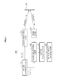
- FIG. 1 illustrates a depth image generating apparatus 100 according to an embodiment.
- the depth image generating apparatus 100 may measure a depth of an object 10 based on a time of flight (TOF) scheme, and may generate a depth image to be used for generating a three-dimensional (3D) image of the object 10.
- the depth image generating apparatus 100 may be included in a depth camera.
- the depth image generating apparatus 100 may measure a distance to the object 10, namely, a depth of a depth image, based on a pixel unit, using a TOF depth sensor.
- the depth image generating apparatus 100 may include a pulse controller 110, a light-emitting unit 120, a lens unit 130, a light-receiving unit 140, a depth calculator 150, and a depth image generator 160.
- the pulse controller 110 may provide various pulse control signals used for measuring the depth of the object 10, to the light-emitting unit 120 and the light-receiving unit 140.
- the pulse controller 110 may generate a waveform of a pulse that the light-emitting unit 120 uses to emit a light, namely, a pulse control signal, and may provide the pulse control signal to the light-emitting unit 120.
- the pulse controller 110 may generate a waveform of a pulse that the light-receiving unit 140 uses to receive a reflected light, namely, a pulse control signal, and may provide the pulse control signal to the light-receiving unit 140.
- the light-emitting unit 120 may emit a light to the object 10 to measure the depth of the object 10.
- the light-emitting unit 120 may emit a light to the object 10 based on a pulse control signal provided form the pulse controller 110.
- a reflected light reflected from the object 10 may be returned to the lens unit 130.
- the light-emitting unit 120 may be embodied as a light emitting diode (LED) array or a laser device. Examples of emitted light may include an ultraviolet ray, a infrared ray, a visible ray, and the like.
- the lens unit 130 may collect a reflected light reflected from the object 10, and may transmit the collected reflected light to the light-receiving unit 140.
- the light-receiving unit 140 may transform the reflected light inputted from the lens unit 130 into electric charge to accumulate the electric charge, and may obtain light information based on an amount of the accumulated electric charge.
- the inputted reflected light may be the same as the received reflected light.
- the light information may be described with reference to FIGS. 4 and 5 .
- the light-receiving unit 140 may receive a reflected light while a waveform of a pulse is in an 'on' state and may accumulate electric charge.
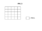
- the light-receiving unit 140 may be embodied as a photo diode array including pixels arranged in two-dimensional (2D) array or as a photo gate array, as illustrated in FIG. 2 .
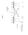
- FIG. 3 illustrates a configuration of a pixel in a pixel array of a light-receiving unit 140 according to an embodiment.
- the pixel may include a plurality of gates to be used to enable electric charge generated from a reflected light to move (through which electric charge generated from a reflected light may pass?).
- a first gate (G1) and a second gate (G2) may receive a reflected light from the lens unit 130 and may generate electric charge.
- the electric charge may pass through a zero gate (G0), the G1 and the G2, and may move to an integrating gate (IG1) or an integrating gate (IG2).
- IG1 or IG2 may move to IG1.
- Electric charge accumulated in IG1 or IG2 may move to a storage gate (SG1) or a storage gate (SG2) via a transmission gate 1 (TG1) or a transmission gate 2 (TG2).
- the SG1 and the SG2 may be a gate to accumulate electric charge, and a quantity of the accumulated electric charge may be used, by the depth calculator 150, to calculate a depth.
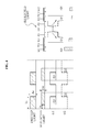
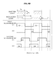
- FIGS. 4 and 5 illustrate an example of a shuttering time of a G1 and a G2 and a movement of a quantity of electric charge according to an embodiment.
- the pulse controller 110 may provide, to the light-emitting unit 120, a pulse control signal for light emission, to measure a depth of the object 10.
- the light-emitting unit 120 may emit a light based on an on-off period set in the pulse control signal.
- To may be a time where a light is emitted from the light-emitting unit 120 during a first period of the pulse.
- t d may be a time taken in a round-trip flight of a light, which may be a time where a light is emitted to the object 10 and a reflected light from the object 10 is projected to the light-receiving unit 140.
- the pulse control signal provided by the pulse controller 110 is 'on', the light-emitting unit 120 may emit a light to the object 10 during To, and when the provided pulse control signal is 'off', the light-emitting unit 120 may not emit a light to the object 10.
- a o may denote an intensity of a light emitted by the light-emitting unit 120
- r may denote a reflexibility of the object 10
- rA o may denote an intensity of a reflected light arriving at the light-receiving unit 140.
- the reflexibility may vary based on a color or a quality of the material of the object 10. At least two quantities of electric charge, namely, Q1 and Q2 may be used to compensate for a distortion due to the reflexibility of the object 10.
- Q1 may denote a quantity of electric charge transformed from a reflected light that a G1 receives.
- Q2 may denote a quantity of electric charge transformed from a reflected light that a G2 receives
- a shuttering time (t s ) may be a time where the G1 or the G2 is open during a single period. Therefore, a first and a second pulse control signal may be a signal to control t s .
- the pulse controller 110 may provide, to the G1 of the light-receiving unit 140, the first pulse control signal that is a control signal of a first pulse for receiving a reflected light, and may provide, to the G2 (of the light receiving unit 140?), the second pulse control signal that is a control signal of a second pulse.
- the pulse controller 110 may simultaneously provide the first pulse control signal and the second pulse control signal to the G1 and the G2, respectively.
- a phase difference between the second pulse control signal and the first pulse control signal may exist.
- the phase difference between the first and the second pulse control signals may be 180 degrees.
- the pulse controller 110 may emit a light, and may turn the G1 on to enable the G1 to receive a reflected light generated by the emitted light. Therefore, the pulse controller 110 may provide, to the G1, the first pulse control signal of which T o is the same as t s of the G1, which means that an on-off period of the first pulse control signal is the same as an on-off period of light emission.
- the G1 may receive a reflected light during (T o -t d ), after t d .
- the IG1 may obtain first light information (nQ1) from a reflected light of a light emitted based on the first pulse control signal.
- the nQ1 may be a total quantity of electric charge transformed from the reflected light that the G1 receives.
- the pulse controller 110 may turn the G1 off, when the light emission is turned off, and may simultaneously turn the G2 on to enable the G2 to receive a reflected light.
- the turning off of the G1 indicates closing of the G1
- the turning on of the G2 indicates opening of the G2.
- the pulse controller 110 may provide, to the G2, the second pulse control signal having a phase difference of 180 degrees with the first pulse control signal.
- the IG2 may obtain second light information (nQ2) from a reflected light of a light emitted based on the second pulse control signal.
- the nQ2 may be a total quantity of electric charge transformed from the reflected light that the G2 receives.
- a first measurement measures during a predetermined time, the quantities of electric charge generated in the G1 and the G2, namely, the nQ1 and the nQ2.
- the nQ1 and the nQ2 may pass through IG1 ⁇ TG1 ⁇ SG1 and IG2 ⁇ TG2 ⁇ SG2, respectively, and may be stored in a frame memory.
- the total quantities of electric charge stored in the frame memory may be nQ1 and nQ2.
- n may denote a number of opens of G1 or G2, or may denote a number of turning-'on's of the first pulse control signal or the second pulse control signal.
- the pulse controller 110 may operates as illustrated in FIG. 5 .
- the pulse controller 110 may provide, to the G1, a third pulse control signal that is a control signal of a third pulse to receive a reflected light, and may provide, to the G2, a fourth pulse control signal that is a control signal of a fourth pulse.
- the pulse controller 110 may simultaneously provide the third pulse control signal and the fourth pulse control signal to the G1 and the G2, respectively.
- a phase difference between the third pulse control signal and the fourth control signal may exist.
- the phase difference between the third pulse control signal and the fourth control signal may be 180 degrees.
- a predetermined phase difference for example, a phase difference of 90 degrees between the first pulse control signal and the third pulse control signal may exist, and a phase difference of 90 degrees between the second pulse control signal and the fourth pulse control signal may exist.
- the pulse controller 110 may provide, to the G1, the third pulse control signal that turns the G1 on T 0 2 after emission of a light. Therefore, T 0 2 after the light is emitted, the pulse controller 110 may provide, to the G1, the third pulse control signal that enables the to receive a reflected light.
- the IG1 may obtain third light information (nQ3) from a reflected light of a light emitted based on the third pulse control signal.
- the nQ3 may be a total quantity of electric charge that is transformed from the reflected light that the G1 receives.
- the pulse controller 110 may simultaneously turn the G2 on to enable the G2 to receive a reflected light, when the G1 is turned off.
- the pulse controller 110 may provide, to the G2, a fourth control signal having a phase difference of 180 degrees with the third pulse control signal.
- the IG2 may obtain fourth light information (nQ4) from a reflected light of a light emitted based on the fourth pulse control signal.
- the nQ4 may be a total quantity of electric charge that is transformed from the reflected light that the G2 receives.
- a second measurement measures during a predetermined time, the quantities of electric charge generated in the G1 and the G2, namely, the nQ3 and the nQ4.
- the nQ3 and the nQ4 may pass through IG1 ⁇ TG1 ⁇ SG and IG2 ⁇ TG2 ⁇ SG2, respectively, and may be stored in a frame memory.
- the total quantities of electric charge stored in the frame memory may be nQ3 and nQ4.
- a maximal measurement distance of a depth may be enhanced more than twice a conventional maximal measurement distance and an accuracy of a measured depth may be maintained or enhanced.
- the depth calculator 150 may calculate a depth of the object 10 based on the nQ1 through the nQ4 obtained from the G1 and the G2 of the light-receiving unit 140, namely, based on accumulated total quantity of electric charge.
- the depth may be calculated based on a pixel unit.
- the depth calculator 150 may calculate a first difference (Y1) and a second difference (Y2).
- the first difference may be a difference between the nQ1 and the nQ2
- the Y2 may be a difference between the nQ3 and the nQ4.
- nQ1 may denote the first light information obtained by the G1 based on the first pulse control signal
- nQ2 may denote the second light information obtained by the G2 based on the second pulse control signal
- nQ3 may denote the third light information obtained by the G1 based on the third pulse control signal
- nQ4 may denote the fourth light information obtained by the G2 based on the fourth pulse control signal.
- the depth calculator 150 may adaptively calculate the depth based on the calculated Y1 and the calculated Y2.
- the depth calculator 150 may calculate, based on difference schemes, the depth for each of a condition where both the Y1 and the Y2 are greater than or equal to zero, a condition where the Y1 is less than zero and the Y2 is greater than or equal to zero, a condition where both the Y1 and the Y2 are less than zero, and a condition where the Y1 is greater than or equal to zero and the Y2 is less than zero.
- the depth calculator 150 may calculate t d based on Equation 2.
- t d may be a time taken in a round-trip flight of a light, which may be a time where a light is emitted to the object 10 and a reflected light from the object 10 is projected to the light-receiving unit 140.
- the depth calculator 150 may calculate t d based on Equation 3.
- the calculator 150 may calculate t d based on Equation 4.
- the depth calculator 150 may calculate t d based on Equation 5.
- the depth calculator 150 may calculate a dept of a pixel by substituting the calculated t d in Equation 6.
- the depth may denote the depth of the pixel
- C may denote a speed of an emitted light or a reflected light
- t d may denote time taken in a round-trip flight of a light that is calculated based on one of Equation 2 through Equation 5.
- C may use a speed of light, for example, 3 ⁇ 10 8 m/s, which is merely an example.
- the depth calculator 150 may calculate a depth of each of pixels of the object 10 based on the described method.
- the depth image generator unit 160 may generate a depth image corresponding to the object 10 based on the calculated depth of each of the pixels.
- a depth of a pixel which may be a distance between the depth image generating apparatus 100 and the corresponding pixel, may be a real number.
- a brightness image of n-bit may be represented by an integer number in a display device.
- the brightness image of eight-bit may be represented by an integer number in a range between 0 through 255 in the display device. Therefore, the depth image generator 160 may normalize the depth to be eight-bit.
- the normalization may be performed based on a maximal distance value that is available in measuring the object 10. For example, when the maximal measurement distance of the depth image generating apparatus 100 is 10 m and the measured depth is 5 m, the depth image generator 160 may normalize the depth into based on eight-bit value. In this example, when 10 m that is the maximal measurement distance is changed into 255 that is a maximal value of the eight-bit value, and 5 m may be changed into 127 or 128.
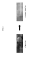
- FIG. 6 illustrates an example of the object 10 and a depth image of the object 10 according to an embodiment.
- the depth image generator 160 may apply normalization with respect to all pixels, to generate a depth image as illustrated in FIG. 6 .
- a bright portion in the depth image may indicate that a distance between the object 10 and the depth image generating apparatus 100 is relatively short, and a dark portion in the depth image may indicate that a distance between the object 10 and the depth image generating apparatus 100 is relatively long.
- FIG. 7 illustrates an example of generating a 3D image according to an embodiment.
- the 3D image may be generated based on a brightness image of the object 10 and a depth image generated by the depth image generator 160.
- Equation 2 through Equation 5 A method of generalizing Equation 2 through Equation 5 may be described, Equation 2 through Equation 5 being used to calculate t d based on an Y1 and an Y2.
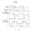
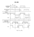
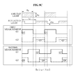
- FIGS. 8A through 8D illustrate examples of a quantity of electric charge generated based on t d according to an embodiment.
- FIG. 8A illustrates quantities of electric charge generated in a G1 and a G2, namely, nQ1 through nQ4, when 0 ⁇ t d ⁇ T 0 2 .
- FIG. 8B illustrates quantities of electric charge generated in a G1 and a G2, namely, nQ1 through nQ4, when T 0 2 ⁇ t d ⁇ T 0 .
- the Y1 and the Y2 are calculated based on the quantities of electric charge of FIG. 8B , the Y1 is less than zero and the Y2 is greater than or equal to zero.
- FIG. 8C illustrates quantities of electric charge generated in a G1 and a G2, namely, nQ1 through nQ4, when T 0 ⁇ t d ⁇ 3 ⁇ T 0 2 .
- FIG. 8D illustrates quantities of electric charge generated in a G1 and a G2, namely, nQ1 and nQ4, when 3 ⁇ T 0 2 ⁇ t d ⁇ 2 ⁇ T 0 .
- the Y1 and the Y2 are calculated based on the quantities of electric charge of FIG. 8D , the Y1 is greater than or equal to aero and the Y2 is less than zero.
- FIG. 9 illustrates a graph with respect to an Y1 and an Y2 varying based on t d of FIGS. 8A through 8D
- A, B, C, and D correspond to FIG. 8A , FIG. 8B , FIG. 8C , and FIG. 8D , respectively.
- the Y1 and the Y2 in a period A may show a change in the quantities of electric charge of FIG. 8A .
- the Y1 decreases and the Y2 increases in its initial period where a first pulse control signal and a second pulse control signal are provided to a G1 and a G2, respectively.
- a period B both the Y1 and the Y2 decrease.
- a period C the Y1 increases and the Y2 decreases.
- both the Y1 and the Y2 increase. Accordingly, the Y1 and the Y2 vary based on t d , which may indicate that t d affects nQ1 through nQ4 obtained by the G1 and the G2.
- Equation 2 through Equation 5 correspond to the period A through period D, respectively.
- FIG. 10 illustrates a depth image generating method of a depth image generating apparatus according to an embodiment.
- the depth image generating method may be performed by the depth image generating apparatus 100 of FIG. 1 .
- the depth image generating apparatus 100 provides a first pulse control signal to a G1 of the light-receiving unit 140, and provides a second pulse control signal to a G2, during a predetermined time.
- the first pulse control signal may have an on-off period same as a pulse provided to the light-emitting unit 120.
- a phase difference between the first pulse control signal and the second pulse control signal may be 180 degrees. Therefore, the second pulse control signal is turned off, when the first pulse control signal is turned on.
- the depth image generating apparatus 100 obtains nQ1 through the G1 and obtains nQ2 through the G2.
- the depth image generating apparatus 100 provides, to the G1, a third pulse control signal to receive a reflected light, and provide, to the G2, a fourth pulse control signal, during a predetermined time.
- the third pulse control signal may have a waveform that is to be turned on T 0 /2 after an emitted light.
- a phase difference between the third pulse control signal and the fourth pulse control signal may be 180 degrees. Therefore, the fourth pulse control signal may be turned off, when the third pulse control signal is turned on.
- the depth image generating apparatus 100 obtains the nQ3 through the G1 and obtains nQ4 through the G2.
- the depth image generating apparatus 100 calculates an Y1 and an Y2 based on Equation 1, the Y1 being a difference between nQ1 and nQ2 and the Y2 being a difference between nQ3 and nQ4.
- the Y1 and the Y2 may be used to calculate t d that is a time taken in round-trip flight of a light to a pixel.
- the depth image generating apparatus 100 calculates t d based on Equation 2 in operation 1040.
- the depth image generating apparatus 100 calculates t d based on Equation 3 in operation 1050.
- the depth image generating apparatus 100 calculates t d based on Equation 4 in operation 1060.
- the depth image generating apparatus 100 calculates t d based on Equation 5 in operation 1070.
- the depth image generating apparatus 100 may calculate a depth of each pixel based on the calculated t d and Equation 6 in operation 1075.
- the depth image generating apparatus 100 normalizes the calculated depth of each pixel to generate a depth image of the object 10.
- the depth image generating apparatus 100 and the method thereof may obtain, based on a configuration of a pixel, a quantity of electric charge generated due to a reflected light, and may calculate a depth based on the obtained quantity of electric charge.
- the depth image generating apparatus 100 and the method thereof may adjust a shuttering time of a gate, such as the G1 and the G2, included in the pixel, to calculate the depth and thus, a maximal measurement distance may be extended without a complexity in operations and an accuracy of the depth may be maintained.
- Non-transitory computer-readable media including program instructions to implement various operations embodied by a computer.
- the media may also include, alone or in combination with the program instructions, data files, data structures, and the like.
- Examples of non-transitory computer-readable media include magnetic media such as hard disks, floppy disks, and magnetic tape; optical media such as CD ROM disks and DVDs; magneto-optical media such as optical disks; and hardware devices that are specially configured to store and perform program instructions, such as read-only memory (ROM), random access memory (RAM), flash memory, and the like.
- Examples of program instructions include both machine code, such as produced by a compiler, and files containing higher level code that may be executed by the computer using an interpreter.
- the described hardware devices may be configured to act as one or more software modules in order to perform the operations of the above-described embodiments, or vice versa.
- the non-transitory computer-readable media may also be a distributed network, so that the program instructions are stored and executed in a distributed fashion.
- the program instructions may be executed by one or more processors or processing devices.
- the computer-readable media may also be embodied in at least one application specific integrated circuit (ASIC) or Field Programmable Gate Array (FPGA).
- ASIC application specific integrated circuit
- FPGA Field Programmable Gate Array
Landscapes
- Engineering & Computer Science (AREA)
- Physics & Mathematics (AREA)
- Electromagnetism (AREA)
- Computer Networks & Wireless Communication (AREA)
- General Physics & Mathematics (AREA)
- Radar, Positioning & Navigation (AREA)
- Remote Sensing (AREA)
- Multimedia (AREA)
- Signal Processing (AREA)
- Optical Radar Systems And Details Thereof (AREA)
- Measurement Of Optical Distance (AREA)
Abstract
Description
- Embodiments relate to a depth image generating apparatus and method, and more particularly, to a depth image generating apparatus and method that may extend a maximal measurement distance of a depth and may maintain an accuracy of the measured depth.
- A three-dimensional (3D) image may include a color image and a depth image. The depth image may be obtained based on a time of flight (TOF) scheme. An infrared ray-based depth camera may emit an infrared ray to an object, may sense a reflected light from the object, and may measure a TOF to calculate a distance between the camera and the object. The calculated distance may be used as a depth of the depth image.
- When a conventional depth camera measures a distance, a maximal measurement distance is limited and thus, the measured distance may often exceed the maximal measurement distance. In this example, the measured distance may be recorded as a smaller value than the maximal measurement distance. Therefore, sometimes, the conventional depth camera may not accurately measure a distance to the object due to the limited maximal measurement distance. When the maximal measurement distance is extended, an accuracy of the measured distance may decrease.
- In an aspect of one or more embodiments, there is provided a depth image generating apparatus, which may include a light-receiving unit including a first gate and a second gate, and a depth calculator to calculate a depth as the depth of the depth image based on first light information through fourth light information, and the first gate may obtain the first light information from a reflected light of a light emitted based on a first pulse and the second gate may obtain the second light information from a reflected light of a light emitted based on a second pulse, and then the first gate may obtain the third light information from a reflected light of a light emitted based on a third pulse and the second gate may obtain the fourth light information from a reflected light of a light emitted based on a fourth pulse.
- A depth calculator may calculate the depth based on a first difference and a second difference, the first difference being a difference between the first light information and the second light information and the second difference being a difference between the third light information and the fourth light information.
- A depth calculator may calculate, based on different schemes, the depth for each of a condition where both the first difference and the second difference are greater than or equal to zero, a condition where the first difference is less than zero and the second difference is greater than or equal to zero, a condition where both the first difference and the second difference are less than zero, and a condition where the first difference is greater than or equal to zero and the second difference is less than zero.
- One or more embodiments of a depth image generating apparatus may further include a pulse controller to simultaneously provide the first pulse and the second pulse to the first gate and the second gate, respectively, and then, to simultaneously provide the third pulse and the fourth pulse to the first gate and the second gate, respectively.
- A phase difference between the first pulse and the second pulse may be 180 degrees, a phase difference between the third pulse and the fourth pulse may be 180 degrees, a phase difference between the first pulse and the third pulse may be 90 degrees, and a phase difference between the second pulse and the fourth pulse may be 90 degrees.
- An on-off period of the first pulse may be the same as an on-off period of light emission, and the third pulse may be generated after the light emission, wherein the period of the third pulse is one-half of the period of the first pulse.
- A depth image generating apparatus of one or more embodiments may be included in a depth camera.
- The first and second gates of a depth image generating apparatus of one or more embodiments may be included in a pixel.
- In one or more embodiments of a depth image apparatus, at least one of a shuttering time of the first gate and a shuttering time of the second gate is adjusted to extend a maximal measurement distance and to calculate the depth of the image.
- In an aspect of one or more embodiments, there is provided a depth image generating method, which may include obtaining first light information and second light information respectively from a reflected light of a light emitted based on a first pulse and from a reflected light of a light emitted based on a second pulse, obtaining third light information and fourth light information respectively from a reflected light of a light emitted based on a third pulse and from a reflected light of a light emitted based on a fourth pulse, and calculating a depth as the depth of the depth image based on the first light information through the fourth light information.
- Calculating based on the first light information through the fourth light information may include calculating the depth based on a first difference and a second difference, the first difference being a difference between the first light information and the second light information and the second difference being a difference between the third light information and the fourth light information.
- Calculating based on the first difference and the second difference may include calculating, based on different schemes, the depth for each of a condition where both the first difference and the second difference are greater than or equal to zero, a condition where the first difference is less than zero and the second difference is greater than or equal to zero, a condition where both the first difference and the second difference are less than zero, and a condition where the first difference is greater than or equal to zero and the second difference is less than zero.
- The first light information may include a total quantity of electric charge from the reflected light of the light emitted on the first pulse signal; the second light information comprises a total quantity of electric charge from the reflected light of the light emitted on the second pulse signal.
- The third light information may include a total quantity of electric charge from the reflected light of the light emitted on the third pulse signal; the fourth light information comprises a total quantity of electric charge from the reflected light of the light emitted on the fourth pulse signal.
- The depth may be calculated based on a difference between the first total quantity of electric charge and the second total quantity of electric charge, and based on the difference between the third total quantity of electric charge and the fourth total quantity of electric charge.
- In an aspect of one or more embodiments, a depth image generating method may further include adjusting at least one of a shuttering time of the first gate and a shuttering time of the second gate to extend a maximal measurement distance and to calculate the depth.
- In an aspect of one or more embodiments, there is provided a depth image generating method, which may include measuring, during a first predetermined time, a first total quantity of electric charge in a first gate from a first reflected light of light emitted on a first pulse control signal, and a second total quantity of electric charge in a second gate from a second reflected light of a light emitted on a second pulse control signal; calculating a first difference between the first total quantity of electric charge and the second total quantity of electric charge; measuring, during a second predetermined time, a third total quantity of electric charge in the first gate from a third reflected light of a light emitted on a third pulse control signal, and a fourth total quantity of electric charge in the second gate from a fourth reflected light of a light emitted on a fourth pulse control signal; calculating a second difference between the third total quantity of electric charge and the fourth total quantity of electric charge; and calculating a maximal measurement distance of a depth as the depth of the depth image based on the first difference and the second difference.
- In an aspect of one or more embodiments, a depth image generating method may further include adjusting at least one of a shuttering time of the first gate and a shuttering time of the second gate to extend a maximal measurement distance and to calculate the depth.
- Additional aspects of embodiments will be set forth in part in the description which follows and, in part, will be apparent from the description, or may be learned by practice of the disclosure.
- One or more embodiments may include a depth image generating apparatus and method. One or more embodiments of a depth image generating apparatus and method may enhance a maximal measurement distance of a depth more than twice a conventional one, and may enhance an accuracy of the measured depth. One or more embodiments of a depth image generating apparatus may calculate a time taken in a round-trip flight of a light to an object using a change in a quantity of electric charge, and may calculate the depth based on the calculated time and thus, may increase an accuracy of the depth.
- A three-dimensional (3D) image may be restored based on a depth image and a brightness image. The depth image and the brightness image may be generated based on a maximal measurement distance that is extended compared with a conventional one and thus, the 3D image may be more realistic and stereoscopic. The brightness image may be obtained by a general two-dimensional (2D) camera or a 3D camera.
- Two different brightness images having difference view points may be generated based on a depth image and a brightness image with respect to an object and may be applied to a 3D display device.
- According to another aspect of one or more embodiments, there is provided at least one computer readable medium storing computer readable instructions to implement methods of one or more embodiments.
- These and/or other aspects will become apparent and more readily appreciated from the following description of embodiments, taken in conjunction with the accompanying drawings of which:
-
FIG. 1 is a block diagram illustrating a depth image generating apparatus according to embodiments. -
FIG. 2 is a diagram illustrating a pixel array of a light-receiving unit according to embodiments. -
FIG. 3 is a diagram illustrating a configuration of a pixel in a pixel array of a light-receiving unit according to embodiments. -
FIGS. 4 and5 are diagrams illustrating an example of a shuttering time of a G1 and a G2 and a movement of a quantity of electric charge according to embodiments. -
FIG. 6 is a diagram illustrating an example of an object and a depth image of the object according to embodiments. -
FIG. 7 is a diagram illustrating an example of generating a three-dimensional (3D) image according to embodiments. -
FIGS. 8A through 8D are diagrams illustrating an example of a quantity of electric charge generated based on td according to embodiments. -
FIG. 9 is a graph illustrating an Y1 and an Y2 varying based on td ofFIGS. 8A through 8D . -
FIG. 10 is a flowchart illustrating a depth image generating method of a depth image generating apparatus according to embodiments. - Reference will now be made in detail to embodiments, examples of which are illustrated in the accompanying drawings, wherein like reference numerals refer to the like elements throughout. Embodiments are described below to explain the present disclosure by referring to the figures
-
FIG. 1 illustrates a depthimage generating apparatus 100 according to an embodiment. - Referring to
FIG. 1 , the depthimage generating apparatus 100 may measure a depth of anobject 10 based on a time of flight (TOF) scheme, and may generate a depth image to be used for generating a three-dimensional (3D) image of theobject 10. The depthimage generating apparatus 100 may be included in a depth camera. - The depth
image generating apparatus 100 may measure a distance to theobject 10, namely, a depth of a depth image, based on a pixel unit, using a TOF depth sensor. The depthimage generating apparatus 100 may include apulse controller 110, a light-emitting unit 120, alens unit 130, a light-receiving unit 140, adepth calculator 150, and adepth image generator 160. - The
pulse controller 110 may provide various pulse control signals used for measuring the depth of theobject 10, to the light-emitting unit 120 and the light-receiving unit 140. Thepulse controller 110 may generate a waveform of a pulse that the light-emittingunit 120 uses to emit a light, namely, a pulse control signal, and may provide the pulse control signal to the light-emitting unit 120. Also, thepulse controller 110 may generate a waveform of a pulse that the light-receivingunit 140 uses to receive a reflected light, namely, a pulse control signal, and may provide the pulse control signal to the light-receivingunit 140. - The light-emitting
unit 120 may emit a light to theobject 10 to measure the depth of theobject 10. The light-emittingunit 120 may emit a light to theobject 10 based on a pulse control signal provided form thepulse controller 110. A reflected light reflected from theobject 10 may be returned to thelens unit 130. The light-emittingunit 120 may be embodied as a light emitting diode (LED) array or a laser device. Examples of emitted light may include an ultraviolet ray, a infrared ray, a visible ray, and the like. - The
lens unit 130 may collect a reflected light reflected from theobject 10, and may transmit the collected reflected light to the light-receivingunit 140. - The light-receiving
unit 140 may transform the reflected light inputted from thelens unit 130 into electric charge to accumulate the electric charge, and may obtain light information based on an amount of the accumulated electric charge. In this example, the inputted reflected light may be the same as the received reflected light. The light information may be described with reference toFIGS. 4 and5 . The light-receivingunit 140 may receive a reflected light while a waveform of a pulse is in an 'on' state and may accumulate electric charge. The light-receivingunit 140 may be embodied as a photo diode array including pixels arranged in two-dimensional (2D) array or as a photo gate array, as illustrated inFIG. 2 . -
FIG. 3 illustrates a configuration of a pixel in a pixel array of a light-receivingunit 140 according to an embodiment. - The pixel may include a plurality of gates to be used to enable electric charge generated from a reflected light to move (through which electric charge generated from a reflected light may pass?).
- A first gate (G1) and a second gate (G2) may receive a reflected light from the
lens unit 130 and may generate electric charge. The electric charge may pass through a zero gate (G0), the G1 and the G2, and may move to an integrating gate (IG1) or an integrating gate (IG2). For example, when the G1 is closed and the G2 is open, the electric charge may move to IG1. Electric charge accumulated in IG1 or IG2 may move to a storage gate (SG1) or a storage gate (SG2) via a transmission gate 1 (TG1) or a transmission gate 2 (TG2). The SG1 and the SG2 may be a gate to accumulate electric charge, and a quantity of the accumulated electric charge may be used, by thedepth calculator 150, to calculate a depth. - An operation of the light-emitting
unit 120 and the light-receivingunit 140 based on a pulse control signal generated by thepulse controller 110 may be described with reference toFIGS. 4 and5 . -
FIGS. 4 and5 illustrate an example of a shuttering time of a G1 and a G2 and a movement of a quantity of electric charge according to an embodiment. - The
pulse controller 110 may provide, to the light-emittingunit 120, a pulse control signal for light emission, to measure a depth of theobject 10. The light-emittingunit 120 may emit a light based on an on-off period set in the pulse control signal. - To may be a time where a light is emitted from the light-emitting
unit 120 during a first period of the pulse. td may be a time taken in a round-trip flight of a light, which may be a time where a light is emitted to theobject 10 and a reflected light from theobject 10 is projected to the light-receivingunit 140. When the pulse control signal provided by thepulse controller 110 is 'on', the light-emittingunit 120 may emit a light to theobject 10 during To, and when the provided pulse control signal is 'off', the light-emittingunit 120 may not emit a light to theobject 10. - Ao may denote an intensity of a light emitted by the light-emitting
unit 120, r may denote a reflexibility of theobject 10, and rAo may denote an intensity of a reflected light arriving at the light-receivingunit 140. The reflexibility may vary based on a color or a quality of the material of theobject 10. At least two quantities of electric charge, namely, Q1 and Q2 may be used to compensate for a distortion due to the reflexibility of theobject 10. - Q1 may denote a quantity of electric charge transformed from a reflected light that a G1 receives. Q2 may denote a quantity of electric charge transformed from a reflected light that a G2 receives
- A shuttering time (ts) may be a time where the G1 or the G2 is open during a single period. Therefore, a first and a second pulse control signal may be a signal to control ts.
- Referring to
FIG. 4 , thepulse controller 110 may provide, to the G1 of the light-receivingunit 140, the first pulse control signal that is a control signal of a first pulse for receiving a reflected light, and may provide, to the G2 (of thelight receiving unit 140?), the second pulse control signal that is a control signal of a second pulse. In this example, thepulse controller 110 may simultaneously provide the first pulse control signal and the second pulse control signal to the G1 and the G2, respectively. A phase difference between the second pulse control signal and the first pulse control signal may exist. For example, the phase difference between the first and the second pulse control signals may be 180 degrees. - Specifically, the
pulse controller 110 may emit a light, and may turn the G1 on to enable the G1 to receive a reflected light generated by the emitted light. Therefore, thepulse controller 110 may provide, to the G1, the first pulse control signal of which To is the same as ts of the G1, which means that an on-off period of the first pulse control signal is the same as an on-off period of light emission. - The G1 may receive a reflected light during (To-td), after td. The IG1 may obtain first light information (nQ1) from a reflected light of a light emitted based on the first pulse control signal. The nQ1 may be a total quantity of electric charge transformed from the reflected light that the G1 receives.
- The
pulse controller 110 may turn the G1 off, when the light emission is turned off, and may simultaneously turn the G2 on to enable the G2 to receive a reflected light. In this example, the turning off of the G1 indicates closing of the G1 and the turning on of the G2 indicates opening of the G2. Thepulse controller 110 may provide, to the G2, the second pulse control signal having a phase difference of 180 degrees with the first pulse control signal. The IG2 may obtain second light information (nQ2) from a reflected light of a light emitted based on the second pulse control signal. The nQ2 may be a total quantity of electric charge transformed from the reflected light that the G2 receives. - A first measurement measures, during a predetermined time, the quantities of electric charge generated in the G1 and the G2, namely, the nQ1 and the nQ2. The nQ1 and the nQ2 may pass through IG1→TG1→SG1 and IG2→TG2→SG2, respectively, and may be stored in a frame memory. The total quantities of electric charge stored in the frame memory may be nQ1 and nQ2. In this example, n may denote a number of opens of G1 or G2, or may denote a number of turning-'on's of the first pulse control signal or the second pulse control signal.
- When the first pulse control signal and the second pulse control signal are provided to the G1 and the G2, during a predetermined time, the
pulse controller 110 may operates as illustrated inFIG. 5 . - Referring to
FIG. 5 , thepulse controller 110 may provide, to the G1, a third pulse control signal that is a control signal of a third pulse to receive a reflected light, and may provide, to the G2, a fourth pulse control signal that is a control signal of a fourth pulse. In this example, thepulse controller 110 may simultaneously provide the third pulse control signal and the fourth pulse control signal to the G1 and the G2, respectively. - A phase difference between the third pulse control signal and the fourth control signal may exist. For example, the phase difference between the third pulse control signal and the fourth control signal may be 180 degrees. Also, a predetermined phase difference, for example, a phase difference of 90 degrees between the first pulse control signal and the third pulse control signal may exist, and a phase difference of 90 degrees between the second pulse control signal and the fourth pulse control signal may exist.
- The
pulse controller 110 may provide, to the G1, the third pulse control signal that turns the G1 on

pulse controller 110 may provide, to the G1, the third pulse control signal that enables the to receive a reflected light. The IG1 may obtain third light information (nQ3) from a reflected light of a light emitted based on the third pulse control signal. The nQ3 may be a total quantity of electric charge that is transformed from the reflected light that the G1 receives. - The
pulse controller 110 may simultaneously turn the G2 on to enable the G2 to receive a reflected light, when the G1 is turned off. Thepulse controller 110 may provide, to the G2, a fourth control signal having a phase difference of 180 degrees with the third pulse control signal. The IG2 may obtain fourth light information (nQ4) from a reflected light of a light emitted based on the fourth pulse control signal. The nQ4 may be a total quantity of electric charge that is transformed from the reflected light that the G2 receives. - A second measurement measures, during a predetermined time, the quantities of electric charge generated in the G1 and the G2, namely, the nQ3 and the nQ4. The nQ3 and the nQ4 may pass through IG1→TG1→SG and IG2→TG2→SG2, respectively, and may be stored in a frame memory. The total quantities of electric charge stored in the frame memory may be nQ3 and nQ4.
- As described above, the first measurement and the second measurement with respect to the quantities of electric charge based on the first through the fourth control signals of which phases are differences and thus, a maximal measurement distance of a depth may be enhanced more than twice a conventional maximal measurement distance and an accuracy of a measured depth may be maintained or enhanced.
- Referring again to
FIG. 1 , thedepth calculator 150 may calculate a depth of theobject 10 based on the nQ1 through the nQ4 obtained from the G1 and the G2 of the light-receivingunit 140, namely, based on accumulated total quantity of electric charge. The depth may be calculated based on a pixel unit. - The
depth calculator 150 may calculate a first difference (Y1) and a second difference (Y2). The first difference may be a difference between the nQ1 and the nQ2, and the Y2 may be a difference between the nQ3 and the nQ4. -

- In Equation 1, nQ1 may denote the first light information obtained by the G1 based on the first pulse control signal, nQ2 may denote the second light information obtained by the G2 based on the second pulse control signal, nQ3 may denote the third light information obtained by the G1 based on the third pulse control signal, and nQ4 may denote the fourth light information obtained by the G2 based on the fourth pulse control signal.
- When the Y1 and the Y2 are calculated based on Equation 1, the
depth calculator 150 may adaptively calculate the depth based on the calculated Y1 and the calculated Y2. - The
depth calculator 150 may calculate, based on difference schemes, the depth for each of a condition where both the Y1 and the Y2 are greater than or equal to zero, a condition where the Y1 is less than zero and the Y2 is greater than or equal to zero, a condition where both the Y1 and the Y2 are less than zero, and a condition where the Y1 is greater than or equal to zero and the Y2 is less than zero. - First, when both the Y1 and the Y2 are greater than or equal to zero, namely, Y1≥0, Y2≥0, the
depth calculator 150 may calculate td based onEquation 2. td may be a time taken in a round-trip flight of a light, which may be a time where a light is emitted to theobject 10 and a reflected light from theobject 10 is projected to the light-receivingunit 140. -

- Second, when the Y1 is less than zero and the Y2 is greater than or equal to zero, namely, Y1<0, Y2≥0, the
depth calculator 150 may calculate td based on Equation 3. -

- Third, when both the Y1 and the Y2 are less than zero, namely, Y1<0, Y2<0, the
calculator 150 may calculate td based onEquation 4. -

- Fourth, when the Y1 is greater than or equal to zero and the Y2 is less than zero, namely, Y1≥0, Y2<0, the
depth calculator 150 may calculate td based onEquation 5. -

- When td is calculated based on one of
Equation 2 throughEquation 5, thedepth calculator 150 may calculate a dept of a pixel by substituting the calculated td in Equation 6. -

- In Equation 6, the depth may denote the depth of the pixel, C may denote a speed of an emitted light or a reflected light, and td may denote time taken in a round-trip flight of a light that is calculated based on one of
Equation 2 throughEquation 5. C may use a speed of light, for example, 3×10⁸m/s, which is merely an example. Thedepth calculator 150 may calculate a depth of each of pixels of theobject 10 based on the described method. - The depth
image generator unit 160 may generate a depth image corresponding to theobject 10 based on the calculated depth of each of the pixels. A depth of a pixel, which may be a distance between the depthimage generating apparatus 100 and the corresponding pixel, may be a real number. However, a brightness image of n-bit may be represented by an integer number in a display device. For example, the brightness image of eight-bit may be represented by an integer number in a range between 0 through 255 in the display device. Therefore, thedepth image generator 160 may normalize the depth to be eight-bit. - The normalization may be performed based on a maximal distance value that is available in measuring the
object 10. For example, when the maximal measurement distance of the depthimage generating apparatus 100 is 10 m and the measured depth is 5 m, thedepth image generator 160 may normalize the depth into based on eight-bit value. In this example, when 10 m that is the maximal measurement distance is changed into 255 that is a maximal value of the eight-bit value, and 5 m may be changed into 127 or 128. -
FIG. 6 illustrates an example of theobject 10 and a depth image of theobject 10 according to an embodiment. Thedepth image generator 160 may apply normalization with respect to all pixels, to generate a depth image as illustrated inFIG. 6 . A bright portion in the depth image may indicate that a distance between theobject 10 and the depthimage generating apparatus 100 is relatively short, and a dark portion in the depth image may indicate that a distance between theobject 10 and the depthimage generating apparatus 100 is relatively long. -
FIG. 7 illustrates an example of generating a 3D image according to an embodiment. The 3D image may be generated based on a brightness image of theobject 10 and a depth image generated by thedepth image generator 160. - A method of generalizing
Equation 2 throughEquation 5 may be described,Equation 2 throughEquation 5 being used to calculate td based on an Y1 and an Y2. -
FIGS. 8A through 8D illustrate examples of a quantity of electric charge generated based on td according to an embodiment. -
FIG. 8A illustrates quantities of electric charge generated in a G1 and a G2, namely, nQ1 through nQ4, when
FIG. 8A , both the Y1 and the Y2 are greater than or equal to zero. -
FIG. 8B illustrates quantities of electric charge generated in a G1 and a G2, namely, nQ1 through nQ4, when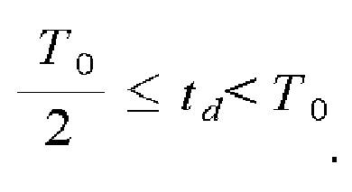
FIG. 8B , the Y1 is less than zero and the Y2 is greater than or equal to zero. -
FIG. 8C illustrates quantities of electric charge generated in a G1 and a G2, namely, nQ1 through nQ4, when
FIG. 8C , both the Y1 and the Y2 are less than zero. -
FIG. 8D illustrates quantities of electric charge generated in a G1 and a G2, namely, nQ1 and nQ4, when
FIG. 8D , the Y1 is greater than or equal to aero and the Y2 is less than zero. -
FIG. 9 illustrates a graph with respect to an Y1 and an Y2 varying based on td ofFIGS. 8A through 8D - Referring to
FIG. 9 , A, B, C, and D correspond toFIG. 8A ,FIG. 8B ,FIG. 8C , andFIG. 8D , respectively. For example, the Y1 and the Y2 in a period A may show a change in the quantities of electric charge ofFIG. 8A . - In the period A, the Y1 decreases and the Y2 increases in its initial period where a first pulse control signal and a second pulse control signal are provided to a G1 and a G2, respectively. In a period B, both the Y1 and the Y2 decrease. In a period C, the Y1 increases and the Y2 decreases. In a period D, both the Y1 and the Y2 increase. Accordingly, the Y1 and the Y2 vary based on td, which may indicate that td affects nQ1 through nQ4 obtained by the G1 and the G2.
- Therefore, the depth
image generating apparatus 100 or a separate operation device may draw, based on the characteristics described inFIG. 9 ,Equation 2 throughEquation 5 to calculate td.Equation 2 throughEquation 5 correspond to the period A through period D, respectively. -
FIG. 10 illustrates a depth image generating method of a depth image generating apparatus according to an embodiment. - Referring to
FIG. 10 , the depth image generating method may be performed by the depthimage generating apparatus 100 ofFIG. 1 . - In
operation 1010, the depthimage generating apparatus 100 provides a first pulse control signal to a G1 of the light-receivingunit 140, and provides a second pulse control signal to a G2, during a predetermined time. The first pulse control signal may have an on-off period same as a pulse provided to the light-emittingunit 120. A phase difference between the first pulse control signal and the second pulse control signal may be 180 degrees. Therefore, the second pulse control signal is turned off, when the first pulse control signal is turned on. - In
operation 1015, the depthimage generating apparatus 100 obtains nQ1 through the G1 and obtains nQ2 through the G2. - In
operation 1020, the depthimage generating apparatus 100 provides, to the G1, a third pulse control signal to receive a reflected light, and provide, to the G2, a fourth pulse control signal, during a predetermined time. The third pulse control signal may have a waveform that is to be turned on T0/2 after an emitted light. A phase difference between the third pulse control signal and the fourth pulse control signal may be 180 degrees. Therefore, the fourth pulse control signal may be turned off, when the third pulse control signal is turned on. - In
operation 1025, the depthimage generating apparatus 100 obtains the nQ3 through the G1 and obtains nQ4 through the G2. - In
operation 1030, the depthimage generating apparatus 100 calculates an Y1 and an Y2 based on Equation 1, the Y1 being a difference between nQ1 and nQ2 and the Y2 being a difference between nQ3 and nQ4. The Y1 and the Y2 may be used to calculate td that is a time taken in round-trip flight of a light to a pixel. - First, when both the Y1 and the Y2 are greater than or equal to zero, namely, Y1≥0, Y2≥0 in
operation 1035, the depthimage generating apparatus 100 calculates td based onEquation 2 inoperation 1040. - Second, when the Y1 is less than zero and the Y2 is greater than or equal to zero, namely, Y1<0, Y2≥0 in
operation 1045, the depthimage generating apparatus 100 calculates td based on Equation 3 inoperation 1050. - Third, when both the Y1 and the Y2 are less than zero, namely, Y1<0, Y2<0 in
operation 1055, the depthimage generating apparatus 100 calculates td based onEquation 4 inoperation 1060. - Forth, when the Y1 is greater than or equal to zero and the Y2 is less than zero, namely, Y1≥0, Y2<0 in
operation 1065, the depthimage generating apparatus 100 calculates td based onEquation 5 inoperation 1070. - When td is calculated with respect to all pixels through
operations 1010 through 1070, the depthimage generating apparatus 100 may calculate a depth of each pixel based on the calculated td and Equation 6 inoperation 1075. - In
operation 1080, the depthimage generating apparatus 100 normalizes the calculated depth of each pixel to generate a depth image of theobject 10. - The depth
image generating apparatus 100 and the method thereof may obtain, based on a configuration of a pixel, a quantity of electric charge generated due to a reflected light, and may calculate a depth based on the obtained quantity of electric charge. The depthimage generating apparatus 100 and the method thereof may adjust a shuttering time of a gate, such as the G1 and the G2, included in the pixel, to calculate the depth and thus, a maximal measurement distance may be extended without a complexity in operations and an accuracy of the depth may be maintained. - Methods according to the above-described embodiments may be recorded in non-transitory computer-readable media including program instructions to implement various operations embodied by a computer. The media may also include, alone or in combination with the program instructions, data files, data structures, and the like. Examples of non-transitory computer-readable media include magnetic media such as hard disks, floppy disks, and magnetic tape; optical media such as CD ROM disks and DVDs; magneto-optical media such as optical disks; and hardware devices that are specially configured to store and perform program instructions, such as read-only memory (ROM), random access memory (RAM), flash memory, and the like. Examples of program instructions include both machine code, such as produced by a compiler, and files containing higher level code that may be executed by the computer using an interpreter. The described hardware devices may be configured to act as one or more software modules in order to perform the operations of the above-described embodiments, or vice versa.
- The non-transitory computer-readable media may also be a distributed network, so that the program instructions are stored and executed in a distributed fashion. The program instructions may be executed by one or more processors or processing devices. The computer-readable media may also be embodied in at least one application specific integrated circuit (ASIC) or Field Programmable Gate Array (FPGA).
- Although embodiments have been shown and described, it would be appreciated by those skilled in the art that changes may be made in these embodiments without departing from the principles of the disclosure, the scope of which is defined by the claims and their equivalents.
Claims (15)
- An apparatus for generating a depth image, the apparatus comprising:a light-receiving unit (140) including a first gate and a second gate; anda depth calculator (150) to calculate a depth as the depth of the depth image based on first light information through fourth light information,wherein the first gate obtains the first light information from a reflected light of a light emitted based on a first pulse and the second gate obtains the second light information from a reflected light of a light emitted based on a second pulse, and then the first gate obtains the third light information from a reflected light of a light emitted based on a third pulse and the second gate obtains the fourth light information from a reflected light of a light emitted based on a fourth pulse.
- The apparatus of claim 1, wherein the depth calculator (150) calculates the depth based on a first difference and a second difference, the first difference being a difference between the first light information and the second light information and the second difference being a difference between the third light information and the fourth light information.
- The apparatus of claim 2, wherein the depth calculator (150) calculates, based on different schemes, the depth for each of a condition where both the first difference and the second difference are greater than or equal to zero, a condition where the first difference is less than zero and the second difference is greater than or equal to zero, a condition where both the first difference and the second difference are less than zero, and a condition where the first difference is greater than or equal to zero and the second difference is less than zero.
- The apparatus according to any of claims 1-3, further comprising:a pulse controller (110) to simultaneously provide the first pulse and the second pulse to the first gate and the second gate, respectively, and then, to simultaneously provide the third pulse and the fourth pulse to the first gate and the second gate, respectively.
- The apparatus according to any of claims 1-4, wherein a phase difference between the first pulse and the second pulse is 180 degrees, a phase difference between the third pulse and the fourth pulse is 180 degrees, a phase difference between the first pulse and the third pulse is 90 degrees, and a phase difference between the second pulse and the fourth pulse is 90 degrees.
- The apparatus of claim 5, wherein an on-off period of the first pulse is the same as an on-off period of light emission, and the third pulse is generated after the light emission, and wherein the period of the third pulse is one-half of the period of the first pulse.
- A method for generating a depth image, the method comprising:obtaining first light information and second light information respectively from a reflected light of a light emitted based on a first pulse and from a reflected light of a light emitted based on a second pulse;obtaining third light information and fourth light information respectively from a reflected light of a light emitted based on a third pulse and from a reflected light of a light emitted based on a fourth pulse; andcalculating a depth as the depth of the depth image based on the first light information through the fourth light information.
- The method of claim 7, wherein the calculating based on the first light information through the fourth light information comprises:calculating the depth based on a first difference and a second difference, the first difference being a difference between the first light information and the second light information and the second difference being a difference between the third light information and the fourth light information.
- The method of claim 8, wherein the calculating based on the first difference and the second difference comprises calculating, based on different schemes, the depth for each of a condition where both the first difference and the second difference are greater than or equal to zero, a condition where the first difference is less than zero and the second difference is greater than or equal to zero, a condition where both the first difference and the second difference are less than zero, and a condition where the first difference is greater than or equal to zero and the second difference is less than zero.
- The method of claim 7, wherein the first pulse and the second pulse are simultaneously provided to the first gate and the second gate, respectively, and then, the third pulse and the fourth pulse are simultaneously provided to the first gate and the second gate, respectively.
- The method of claim 7, wherein a phase difference between the first pulse and the second pulse is 180 degrees, a phase difference between the third pulse and the fourth pulse is 180 degrees, a phase difference between the first pulse and the third pulse is 90 degrees, and a phase difference between the second pulse and the fourth pulse is 90 degrees.
- The method of claim 11, wherein an on-off period of the first pulse is the same as an on-off period of light emission, and the third pulse is generated after the light emission, and wherein the period of the third pulse is one-half of the period of the first pulse.
- The method of claim 7, wherein:the first light information comprises a total quantity of electric charge from the reflected light of the light emitted on the first pulse signal;the second light information comprises a total quantity of electric charge from the reflected light of the light emitted on the second pulse signal;the third light information comprises a total quantity of electric charge from the reflected light of the light emitted on the third pulse signal;the fourth light information comprises a total quantity of electric charge from the reflected light of the light emitted on the fourth pulse signal; andthe depth is calculated based on a difference between the first total quantity of electric charge and the second total quantity of electric charge, and based on the difference between the third total quantity of electric charge and the fourth total quantity of electric charge.
- The method of claim 7, further comprising adjusting at least one of a shuttering time of the first gate and a shuttering time of the second gate to extend a maximal measurement distance and to calculate the depth.
- At least one non-transitory computer readable recording medium storing computer readable instructions that control at least one processor to implement the method of claim 7.
Applications Claiming Priority (1)
| Application Number | Priority Date | Filing Date | Title |
|---|---|---|---|
| KR1020100060597A KR101666020B1 (en) | 2010-06-25 | 2010-06-25 | Apparatus and Method for Generating Depth Image |
Publications (3)
| Publication Number | Publication Date |
|---|---|
| EP2402784A2 true EP2402784A2 (en) | 2012-01-04 |
| EP2402784A3 EP2402784A3 (en) | 2014-04-02 |
| EP2402784B1 EP2402784B1 (en) | 2019-08-28 |
Family
ID=44773227
Family Applications (1)
| Application Number | Title | Priority Date | Filing Date |
|---|---|---|---|
| EP11155932.4A Active EP2402784B1 (en) | 2010-06-25 | 2011-02-25 | Apparatus and method for generating depth image |
Country Status (3)
| Country | Link |
|---|---|
| US (1) | US9366759B2 (en) |
| EP (1) | EP2402784B1 (en) |
| KR (1) | KR101666020B1 (en) |
Cited By (7)
| Publication number | Priority date | Publication date | Assignee | Title |
|---|---|---|---|---|
| EP3572835A1 (en) * | 2018-05-14 | 2019-11-27 | Rockwell Automation Technologies, Inc. | Permutation of measuring capacitors in a time-of-flight sensor |
| US10585176B2 (en) | 2017-09-19 | 2020-03-10 | Rockwell Automation Technologies, Inc. | Pulsed-based time of flight methods and system |
| US10663565B2 (en) | 2017-09-19 | 2020-05-26 | Rockwell Automation Technologies, Inc. | Pulsed-based time of flight methods and system |
| CN111580119A (en) * | 2020-05-29 | 2020-08-25 | Oppo广东移动通信有限公司 | Depth camera, electronic device and control method |
| US10789506B2 (en) | 2018-09-24 | 2020-09-29 | Rockwell Automation Technologies, Inc. | Object intrusion detection system and method |
| US10969476B2 (en) | 2018-07-10 | 2021-04-06 | Rockwell Automation Technologies, Inc. | High dynamic range for sensing systems and methods |
| US10996324B2 (en) | 2018-05-14 | 2021-05-04 | Rockwell Automation Technologies, Inc. | Time of flight system and method using multiple measuring sequences |
Families Citing this family (17)
| Publication number | Priority date | Publication date | Assignee | Title |
|---|---|---|---|---|
| TWI470485B (en) * | 2012-03-29 | 2015-01-21 | 緯創資通股份有限公司 | Stylus that detects stroke pressure |
| KR101871235B1 (en) * | 2012-06-05 | 2018-06-27 | 삼성전자주식회사 | Depth image generating method and apparatus, depth image processing method and apparatus |
| US10324033B2 (en) | 2012-07-20 | 2019-06-18 | Samsung Electronics Co., Ltd. | Image processing apparatus and method for correcting an error in depth |
| US20160069999A1 (en) * | 2013-03-25 | 2016-03-10 | Lg Electronics Inc. | Depth image obtaining device and display device using same |
| US9799117B2 (en) | 2013-09-30 | 2017-10-24 | Lenovo (Beijing) Co., Ltd. | Method for processing data and apparatus thereof |
| CN104519342B (en) | 2013-09-30 | 2017-07-21 | 联想(北京)有限公司 | A kind of image processing method and device |
| KR102158212B1 (en) * | 2014-02-05 | 2020-09-22 | 엘지전자 주식회사 | Multispectral camera and control method of the camera for detecting 3d image |
| JP6231940B2 (en) * | 2014-05-08 | 2017-11-15 | 浜松ホトニクス株式会社 | Ranging device and driving method of ranging device |
| CN105872520A (en) * | 2016-04-25 | 2016-08-17 | 京东方科技集团股份有限公司 | Display device and display method |
| EP3471399B1 (en) * | 2016-06-13 | 2025-05-21 | LG Electronics Inc. | Night vision display device |
| CN111034177B (en) * | 2017-09-14 | 2022-06-28 | 新唐科技日本株式会社 | Solid-state imaging device and imaging device including the same |
| WO2019077863A1 (en) * | 2017-10-18 | 2019-04-25 | ソニーセミコンダクタソリューションズ株式会社 | Identification device and electronic apparatus |
| JP7510815B2 (en) * | 2020-02-20 | 2024-07-04 | 浜松ホトニクス株式会社 | Optical coherence tomography |
| EP4172603A4 (en) * | 2020-06-25 | 2024-08-07 | Smiths Detection Inc. | Systems and methods for real-time configurable backscatter scanners |
| DE102021107903A1 (en) * | 2021-03-29 | 2022-09-29 | Conti Temic Microelectronic Gmbh | Method and system for estimating depth information |
| CN113298778B (en) * | 2021-05-21 | 2023-04-07 | 奥比中光科技集团股份有限公司 | Depth calculation method and system based on flight time and storage medium |
| US12566273B2 (en) * | 2023-01-18 | 2026-03-03 | Himax Technologies Limited | Time-of-flight 3D sensing system |
Family Cites Families (10)
| Publication number | Priority date | Publication date | Assignee | Title |
|---|---|---|---|---|
| DE19704496C2 (en) | 1996-09-05 | 2001-02-15 | Rudolf Schwarte | Method and device for determining the phase and / or amplitude information of an electromagnetic wave |
| US7834305B2 (en) * | 2004-07-30 | 2010-11-16 | Panasonic Electric Works Co., Ltd. | Image processing device |
| JP4788187B2 (en) * | 2005-05-02 | 2011-10-05 | パナソニック電工株式会社 | Spatial information detector |
| KR101344490B1 (en) | 2007-11-06 | 2013-12-24 | 삼성전자주식회사 | Image generating method and apparatus |
| KR101367281B1 (en) | 2007-11-13 | 2014-02-25 | 삼성전자주식회사 | Depth image generating method and apparatus |
| EP2116864A1 (en) | 2008-05-09 | 2009-11-11 | Vrije Universiteit Brussel | TOF range finding with background radiation suppression |
| US8035806B2 (en) | 2008-05-13 | 2011-10-11 | Samsung Electronics Co., Ltd. | Distance measuring sensor including double transfer gate and three dimensional color image sensor including the distance measuring sensor |
| JP5585903B2 (en) | 2008-07-30 | 2014-09-10 | 国立大学法人静岡大学 | Distance image sensor and method for generating imaging signal by time-of-flight method |
| KR101483462B1 (en) | 2008-08-27 | 2015-01-16 | 삼성전자주식회사 | Apparatus and Method For Obtaining a Depth Image |
| JP5485288B2 (en) * | 2008-11-25 | 2014-05-07 | テトラビュー, インコーポレイテッド | High resolution 3D imaging system and method |
-
2010
- 2010-06-25 KR KR1020100060597A patent/KR101666020B1/en active Active
-
2011
- 2011-02-16 US US12/929,805 patent/US9366759B2/en active Active
- 2011-02-25 EP EP11155932.4A patent/EP2402784B1/en active Active
Non-Patent Citations (1)
| Title |
|---|
| None |
Cited By (10)
| Publication number | Priority date | Publication date | Assignee | Title |
|---|---|---|---|---|
| US10585176B2 (en) | 2017-09-19 | 2020-03-10 | Rockwell Automation Technologies, Inc. | Pulsed-based time of flight methods and system |
| US10663565B2 (en) | 2017-09-19 | 2020-05-26 | Rockwell Automation Technologies, Inc. | Pulsed-based time of flight methods and system |
| EP3572835A1 (en) * | 2018-05-14 | 2019-11-27 | Rockwell Automation Technologies, Inc. | Permutation of measuring capacitors in a time-of-flight sensor |
| US10996324B2 (en) | 2018-05-14 | 2021-05-04 | Rockwell Automation Technologies, Inc. | Time of flight system and method using multiple measuring sequences |
| US11002836B2 (en) | 2018-05-14 | 2021-05-11 | Rockwell Automation Technologies, Inc. | Permutation of measuring capacitors in a time-of-flight sensor |
| US10969476B2 (en) | 2018-07-10 | 2021-04-06 | Rockwell Automation Technologies, Inc. | High dynamic range for sensing systems and methods |
| US10789506B2 (en) | 2018-09-24 | 2020-09-29 | Rockwell Automation Technologies, Inc. | Object intrusion detection system and method |
| CN111580119A (en) * | 2020-05-29 | 2020-08-25 | Oppo广东移动通信有限公司 | Depth camera, electronic device and control method |
| WO2021238477A1 (en) * | 2020-05-29 | 2021-12-02 | Oppo广东移动通信有限公司 | Depth camera, electronic device, and control method |
| CN111580119B (en) * | 2020-05-29 | 2022-09-02 | Oppo广东移动通信有限公司 | Depth camera, electronic device and control method |
Also Published As
| Publication number | Publication date |
|---|---|
| EP2402784A3 (en) | 2014-04-02 |
| KR101666020B1 (en) | 2016-10-25 |
| US9366759B2 (en) | 2016-06-14 |
| EP2402784B1 (en) | 2019-08-28 |
| KR20120000299A (en) | 2012-01-02 |
| US20110317878A1 (en) | 2011-12-29 |
Similar Documents
| Publication | Publication Date | Title |
|---|---|---|
| EP2402784B1 (en) | Apparatus and method for generating depth image | |
| CN110876006B (en) | Depth image obtained using multiple exposures in combination | |
| EP3210037B1 (en) | Time of flight depth camera | |
| CN104272731B (en) | Apparatus and method for processing 3d information | |
| US8217327B2 (en) | Apparatus and method of obtaining depth image | |
| KR102464236B1 (en) | How to Simulate Continuous Wave LiDAR Sensors | |
| CN107765260B (en) | Method, device, and computer-readable recording medium for acquiring distance information | |
| US12591050B2 (en) | Time of flight ranging system and ranging method thereof | |
| CN111896971B (en) | TOF sensing device and distance detection method | |
| US20160156899A1 (en) | Three-dimensional measurement apparatus and control method for the same | |
| CN108663682A (en) | Barrier range-measurement system and the vehicle with it and TOF measurement method | |
| US20240230910A9 (en) | Time-of-flight data generation circuitry and time-of-flight data generation method | |
| US20230403385A1 (en) | Spad array for intensity image capture and time of flight capture | |
| US12309501B2 (en) | SPAD array for intensity image sensing on head-mounted displays | |
| CN118642068A (en) | Dynamic decision-making method and device based on neural radiation field model | |
| CN111366943A (en) | Flight time ranging system and ranging method thereof | |
| CN119152008A (en) | Depth measurement method and device based on active binocular event camera | |
| US11682140B1 (en) | Methods and apparatus for calibrating stereo cameras using a time-of-flight sensor | |
| CN107923968A (en) | Information processing device, control method, program, and storage medium | |
| US20250080709A1 (en) | Measurement system, information processing apparatus, measurement method, and program | |
| US12094140B2 (en) | Apparatus and method of generating depth map | |
| CN119881929A (en) | A laser radar ranging method and system for time-sharing imaging | |
| CN113447954A (en) | Scene depth measuring method, system, device and storage medium |
Legal Events
| Date | Code | Title | Description |
|---|---|---|---|
| AK | Designated contracting states |
Kind code of ref document: A2 Designated state(s): AL AT BE BG CH CY CZ DE DK EE ES FI FR GB GR HR HU IE IS IT LI LT LU LV MC MK MT NL NO PL PT RO RS SE SI SK SM TR |
|
| AX | Request for extension of the european patent |
Extension state: BA ME |
|
| PUAI | Public reference made under article 153(3) epc to a published international application that has entered the european phase |
Free format text: ORIGINAL CODE: 0009012 |
|
| RAP1 | Party data changed (applicant data changed or rights of an application transferred) |
Owner name: SAMSUNG ELECTRONICS CO., LTD. |
|
| PUAL | Search report despatched |
Free format text: ORIGINAL CODE: 0009013 |
|
| AK | Designated contracting states |
Kind code of ref document: A3 Designated state(s): AL AT BE BG CH CY CZ DE DK EE ES FI FR GB GR HR HU IE IS IT LI LT LU LV MC MK MT NL NO PL PT RO RS SE SI SK SM TR |
|
| AX | Request for extension of the european patent |
Extension state: BA ME |
|
| RIC1 | Information provided on ipc code assigned before grant |
Ipc: G01S 7/486 20060101ALI20140225BHEP Ipc: G01S 17/89 20060101AFI20140225BHEP Ipc: G01S 17/10 20060101ALI20140225BHEP |
|
| 17P | Request for examination filed |
Effective date: 20141001 |
|
| RBV | Designated contracting states (corrected) |
Designated state(s): AL AT BE BG CH CY CZ DE DK EE ES FI FR GB GR HR HU IE IS IT LI LT LU LV MC MK MT NL NO PL PT RO RS SE SI SK SM TR |
|
| STAA | Information on the status of an ep patent application or granted ep patent |
Free format text: STATUS: EXAMINATION IS IN PROGRESS |
|
| 17Q | First examination report despatched |
Effective date: 20170607 |
|
| GRAP | Despatch of communication of intention to grant a patent |
Free format text: ORIGINAL CODE: EPIDOSNIGR1 |
|
| STAA | Information on the status of an ep patent application or granted ep patent |
Free format text: STATUS: GRANT OF PATENT IS INTENDED |
|
| GRAS | Grant fee paid |
Free format text: ORIGINAL CODE: EPIDOSNIGR3 |
|
| INTG | Intention to grant announced |
Effective date: 20190207 |
|
| INTG | Intention to grant announced |
Effective date: 20190215 |
|
| GRAJ | Information related to disapproval of communication of intention to grant by the applicant or resumption of examination proceedings by the epo deleted |
Free format text: ORIGINAL CODE: EPIDOSDIGR1 |
|
| GRAL | Information related to payment of fee for publishing/printing deleted |
Free format text: ORIGINAL CODE: EPIDOSDIGR3 |
|
| STAA | Information on the status of an ep patent application or granted ep patent |
Free format text: STATUS: EXAMINATION IS IN PROGRESS |
|
| GRAP | Despatch of communication of intention to grant a patent |
Free format text: ORIGINAL CODE: EPIDOSNIGR1 |
|
| STAA | Information on the status of an ep patent application or granted ep patent |
Free format text: STATUS: GRANT OF PATENT IS INTENDED |
|
| INTC | Intention to grant announced (deleted) | ||
| INTG | Intention to grant announced |
Effective date: 20190626 |
|
| GRAA | (expected) grant |
Free format text: ORIGINAL CODE: 0009210 |
|
| STAA | Information on the status of an ep patent application or granted ep patent |
Free format text: STATUS: THE PATENT HAS BEEN GRANTED |
|
| INTG | Intention to grant announced |
Effective date: 20190702 |
|
| AK | Designated contracting states |
Kind code of ref document: B1 Designated state(s): AL AT BE BG CH CY CZ DE DK EE ES FI FR GB GR HR HU IE IS IT LI LT LU LV MC MK MT NL NO PL PT RO RS SE SI SK SM TR |
|
| REG | Reference to a national code |
Ref country code: GB Ref legal event code: FG4D |
|
| REG | Reference to a national code |
Ref country code: CH Ref legal event code: EP |
|
| REG | Reference to a national code |
Ref country code: AT Ref legal event code: REF Ref document number: 1173090 Country of ref document: AT Kind code of ref document: T Effective date: 20190915 |
|
| REG | Reference to a national code |
Ref country code: IE Ref legal event code: FG4D |
|
| REG | Reference to a national code |
Ref country code: DE Ref legal event code: R096 Ref document number: 602011061555 Country of ref document: DE |
|
| REG | Reference to a national code |
Ref country code: NL Ref legal event code: MP Effective date: 20190828 |
|
| REG | Reference to a national code |
Ref country code: LT Ref legal event code: MG4D |
|
| PG25 | Lapsed in a contracting state [announced via postgrant information from national office to epo] |
Ref country code: BG Free format text: LAPSE BECAUSE OF FAILURE TO SUBMIT A TRANSLATION OF THE DESCRIPTION OR TO PAY THE FEE WITHIN THE PRESCRIBED TIME-LIMIT Effective date: 20191128 Ref country code: SE Free format text: LAPSE BECAUSE OF FAILURE TO SUBMIT A TRANSLATION OF THE DESCRIPTION OR TO PAY THE FEE WITHIN THE PRESCRIBED TIME-LIMIT Effective date: 20190828 Ref country code: NO Free format text: LAPSE BECAUSE OF FAILURE TO SUBMIT A TRANSLATION OF THE DESCRIPTION OR TO PAY THE FEE WITHIN THE PRESCRIBED TIME-LIMIT Effective date: 20191128 Ref country code: PT Free format text: LAPSE BECAUSE OF FAILURE TO SUBMIT A TRANSLATION OF THE DESCRIPTION OR TO PAY THE FEE WITHIN THE PRESCRIBED TIME-LIMIT Effective date: 20191230 Ref country code: FI Free format text: LAPSE BECAUSE OF FAILURE TO SUBMIT A TRANSLATION OF THE DESCRIPTION OR TO PAY THE FEE WITHIN THE PRESCRIBED TIME-LIMIT Effective date: 20190828 Ref country code: HR Free format text: LAPSE BECAUSE OF FAILURE TO SUBMIT A TRANSLATION OF THE DESCRIPTION OR TO PAY THE FEE WITHIN THE PRESCRIBED TIME-LIMIT Effective date: 20190828 Ref country code: NL Free format text: LAPSE BECAUSE OF FAILURE TO SUBMIT A TRANSLATION OF THE DESCRIPTION OR TO PAY THE FEE WITHIN THE PRESCRIBED TIME-LIMIT Effective date: 20190828 Ref country code: LT Free format text: LAPSE BECAUSE OF FAILURE TO SUBMIT A TRANSLATION OF THE DESCRIPTION OR TO PAY THE FEE WITHIN THE PRESCRIBED TIME-LIMIT Effective date: 20190828 |
|
| PG25 | Lapsed in a contracting state [announced via postgrant information from national office to epo] |
Ref country code: AL Free format text: LAPSE BECAUSE OF FAILURE TO SUBMIT A TRANSLATION OF THE DESCRIPTION OR TO PAY THE FEE WITHIN THE PRESCRIBED TIME-LIMIT Effective date: 20190828 Ref country code: ES Free format text: LAPSE BECAUSE OF FAILURE TO SUBMIT A TRANSLATION OF THE DESCRIPTION OR TO PAY THE FEE WITHIN THE PRESCRIBED TIME-LIMIT Effective date: 20190828 Ref country code: GR Free format text: LAPSE BECAUSE OF FAILURE TO SUBMIT A TRANSLATION OF THE DESCRIPTION OR TO PAY THE FEE WITHIN THE PRESCRIBED TIME-LIMIT Effective date: 20191129 Ref country code: RS Free format text: LAPSE BECAUSE OF FAILURE TO SUBMIT A TRANSLATION OF THE DESCRIPTION OR TO PAY THE FEE WITHIN THE PRESCRIBED TIME-LIMIT Effective date: 20190828 Ref country code: LV Free format text: LAPSE BECAUSE OF FAILURE TO SUBMIT A TRANSLATION OF THE DESCRIPTION OR TO PAY THE FEE WITHIN THE PRESCRIBED TIME-LIMIT Effective date: 20190828 Ref country code: IS Free format text: LAPSE BECAUSE OF FAILURE TO SUBMIT A TRANSLATION OF THE DESCRIPTION OR TO PAY THE FEE WITHIN THE PRESCRIBED TIME-LIMIT Effective date: 20191228 |
|
| REG | Reference to a national code |
Ref country code: AT Ref legal event code: MK05 Ref document number: 1173090 Country of ref document: AT Kind code of ref document: T Effective date: 20190828 |
|
| PG25 | Lapsed in a contracting state [announced via postgrant information from national office to epo] |
Ref country code: TR Free format text: LAPSE BECAUSE OF FAILURE TO SUBMIT A TRANSLATION OF THE DESCRIPTION OR TO PAY THE FEE WITHIN THE PRESCRIBED TIME-LIMIT Effective date: 20190828 |
|
| PG25 | Lapsed in a contracting state [announced via postgrant information from national office to epo] |
Ref country code: EE Free format text: LAPSE BECAUSE OF FAILURE TO SUBMIT A TRANSLATION OF THE DESCRIPTION OR TO PAY THE FEE WITHIN THE PRESCRIBED TIME-LIMIT Effective date: 20190828 Ref country code: PL Free format text: LAPSE BECAUSE OF FAILURE TO SUBMIT A TRANSLATION OF THE DESCRIPTION OR TO PAY THE FEE WITHIN THE PRESCRIBED TIME-LIMIT Effective date: 20190828 Ref country code: DK Free format text: LAPSE BECAUSE OF FAILURE TO SUBMIT A TRANSLATION OF THE DESCRIPTION OR TO PAY THE FEE WITHIN THE PRESCRIBED TIME-LIMIT Effective date: 20190828 Ref country code: AT Free format text: LAPSE BECAUSE OF FAILURE TO SUBMIT A TRANSLATION OF THE DESCRIPTION OR TO PAY THE FEE WITHIN THE PRESCRIBED TIME-LIMIT Effective date: 20190828 Ref country code: RO Free format text: LAPSE BECAUSE OF FAILURE TO SUBMIT A TRANSLATION OF THE DESCRIPTION OR TO PAY THE FEE WITHIN THE PRESCRIBED TIME-LIMIT Effective date: 20190828 Ref country code: IT Free format text: LAPSE BECAUSE OF FAILURE TO SUBMIT A TRANSLATION OF THE DESCRIPTION OR TO PAY THE FEE WITHIN THE PRESCRIBED TIME-LIMIT Effective date: 20190828 |
|
| PG25 | Lapsed in a contracting state [announced via postgrant information from national office to epo] |
Ref country code: CZ Free format text: LAPSE BECAUSE OF FAILURE TO SUBMIT A TRANSLATION OF THE DESCRIPTION OR TO PAY THE FEE WITHIN THE PRESCRIBED TIME-LIMIT Effective date: 20190828 Ref country code: SK Free format text: LAPSE BECAUSE OF FAILURE TO SUBMIT A TRANSLATION OF THE DESCRIPTION OR TO PAY THE FEE WITHIN THE PRESCRIBED TIME-LIMIT Effective date: 20190828 Ref country code: SM Free format text: LAPSE BECAUSE OF FAILURE TO SUBMIT A TRANSLATION OF THE DESCRIPTION OR TO PAY THE FEE WITHIN THE PRESCRIBED TIME-LIMIT Effective date: 20190828 Ref country code: IS Free format text: LAPSE BECAUSE OF FAILURE TO SUBMIT A TRANSLATION OF THE DESCRIPTION OR TO PAY THE FEE WITHIN THE PRESCRIBED TIME-LIMIT Effective date: 20200224 |
|
| REG | Reference to a national code |
Ref country code: DE Ref legal event code: R097 Ref document number: 602011061555 Country of ref document: DE |
|
| PLBE | No opposition filed within time limit |
Free format text: ORIGINAL CODE: 0009261 |
|
| STAA | Information on the status of an ep patent application or granted ep patent |
Free format text: STATUS: NO OPPOSITION FILED WITHIN TIME LIMIT |
|
| PG2D | Information on lapse in contracting state deleted |
Ref country code: IS |
|
| 26N | No opposition filed |
Effective date: 20200603 |
|
| PG25 | Lapsed in a contracting state [announced via postgrant information from national office to epo] |
Ref country code: SI Free format text: LAPSE BECAUSE OF FAILURE TO SUBMIT A TRANSLATION OF THE DESCRIPTION OR TO PAY THE FEE WITHIN THE PRESCRIBED TIME-LIMIT Effective date: 20190828 |
|
| REG | Reference to a national code |
Ref country code: CH Ref legal event code: PL |
|
| REG | Reference to a national code |
Ref country code: BE Ref legal event code: MM Effective date: 20200229 |
|
| PG25 | Lapsed in a contracting state [announced via postgrant information from national office to epo] |
Ref country code: MC Free format text: LAPSE BECAUSE OF FAILURE TO SUBMIT A TRANSLATION OF THE DESCRIPTION OR TO PAY THE FEE WITHIN THE PRESCRIBED TIME-LIMIT Effective date: 20190828 Ref country code: LU Free format text: LAPSE BECAUSE OF NON-PAYMENT OF DUE FEES Effective date: 20200225 |
|
| PG25 | Lapsed in a contracting state [announced via postgrant information from national office to epo] |
Ref country code: CH Free format text: LAPSE BECAUSE OF NON-PAYMENT OF DUE FEES Effective date: 20200229 Ref country code: LI Free format text: LAPSE BECAUSE OF NON-PAYMENT OF DUE FEES Effective date: 20200229 |
|
| PG25 | Lapsed in a contracting state [announced via postgrant information from national office to epo] |
Ref country code: IE Free format text: LAPSE BECAUSE OF NON-PAYMENT OF DUE FEES Effective date: 20200225 |
|
| PG25 | Lapsed in a contracting state [announced via postgrant information from national office to epo] |
Ref country code: BE Free format text: LAPSE BECAUSE OF NON-PAYMENT OF DUE FEES Effective date: 20200229 |
|
| PG25 | Lapsed in a contracting state [announced via postgrant information from national office to epo] |
Ref country code: MT Free format text: LAPSE BECAUSE OF FAILURE TO SUBMIT A TRANSLATION OF THE DESCRIPTION OR TO PAY THE FEE WITHIN THE PRESCRIBED TIME-LIMIT Effective date: 20190828 Ref country code: CY Free format text: LAPSE BECAUSE OF FAILURE TO SUBMIT A TRANSLATION OF THE DESCRIPTION OR TO PAY THE FEE WITHIN THE PRESCRIBED TIME-LIMIT Effective date: 20190828 |
|
| PG25 | Lapsed in a contracting state [announced via postgrant information from national office to epo] |
Ref country code: MK Free format text: LAPSE BECAUSE OF FAILURE TO SUBMIT A TRANSLATION OF THE DESCRIPTION OR TO PAY THE FEE WITHIN THE PRESCRIBED TIME-LIMIT Effective date: 20190828 |
|
| P01 | Opt-out of the competence of the unified patent court (upc) registered |
Effective date: 20230530 |
|
| PGFP | Annual fee paid to national office [announced via postgrant information from national office to epo] |
Ref country code: GB Payment date: 20260112 Year of fee payment: 16 |
|
| PGFP | Annual fee paid to national office [announced via postgrant information from national office to epo] |
Ref country code: DE Payment date: 20260114 Year of fee payment: 16 |
|
| PGFP | Annual fee paid to national office [announced via postgrant information from national office to epo] |
Ref country code: FR Payment date: 20260108 Year of fee payment: 16 |