EP2402774A1 - Method and apparatus for determining distance to phase-to-earth fault - Google Patents
Method and apparatus for determining distance to phase-to-earth fault Download PDFInfo
- Publication number
- EP2402774A1 EP2402774A1 EP10167650A EP10167650A EP2402774A1 EP 2402774 A1 EP2402774 A1 EP 2402774A1 EP 10167650 A EP10167650 A EP 10167650A EP 10167650 A EP10167650 A EP 10167650A EP 2402774 A1 EP2402774 A1 EP 2402774A1
- Authority
- EP
- European Patent Office
- Prior art keywords
- real
- imag
- value
- electric line
- phase
- Prior art date
- Legal status (The legal status is an assumption and is not a legal conclusion. Google has not performed a legal analysis and makes no representation as to the accuracy of the status listed.)
- Granted
Links
Images

Classifications
-
- G—PHYSICS
- G01—MEASURING; TESTING
- G01R—MEASURING ELECTRIC VARIABLES; MEASURING MAGNETIC VARIABLES
- G01R31/00—Arrangements for testing electric properties; Arrangements for locating electric faults; Arrangements for electrical testing characterised by what is being tested not provided for elsewhere
- G01R31/08—Locating faults in cables, transmission lines, or networks
- G01R31/081—Locating faults in cables, transmission lines, or networks according to type of conductors
- G01R31/086—Locating faults in cables, transmission lines, or networks according to type of conductors in power transmission or distribution networks, i.e. with interconnected conductors
-
- G—PHYSICS
- G01—MEASURING; TESTING
- G01R—MEASURING ELECTRIC VARIABLES; MEASURING MAGNETIC VARIABLES
- G01R31/00—Arrangements for testing electric properties; Arrangements for locating electric faults; Arrangements for electrical testing characterised by what is being tested not provided for elsewhere
- G01R31/08—Locating faults in cables, transmission lines, or networks
- G01R31/088—Aspects of digital computing
Definitions
- the invention relates to determining a distance to a phase-to-earth fault on a three-phase electric line of an electric network.
- Step #2 Identification of a faulty phase by monitoring the amplitudes of phase-to-earth voltages. Knowledge of the faulted phase is imperative, as it determines the selection of quantities used in the disclosed fault distance calculation.
- Step #4 The voltage change is the change of voltage in the faulty phase, e.g.
- EP 1304580 describes a fault distance calculation method for compensated networks, which also utilizes changes of measured quantities during the fault.
- the disclosed method is based on measurement on a feeder bay and the equations used in fault distance calculation are derived from a well known symmetrical component equivalent circuit valid for a single phase earth fault.
- the fault current change ⁇ I F is based on the measured residual current and setting Y 00-Leitung , which represents the zero-sequence admittance of the protected line, is used for improving the accuracy of fault current change estimate.
- An object of the present invention is thus to provide a method and an apparatus for implementing the method so as to overcome the above problems or at least to alleviate them.
- the objects of the invention are achieved by a method and an arrangement which are characterized by what is stated in the independent claims.
- the preferred embodiments of the invention are disclosed in the dependent claims.
- the invention is based on the idea of using a change in a residual voltage of the electric network as an approximation of a change in a voltage in the faulty phase.
- the invention is based on modeling the zero sequence circuit of the electric network.
- An advantage of the method and arrangement of the invention is that only the residual voltage and zero sequence current values are needed for the distance calculation instead of all phase-to-earth voltages and all phase currents.
- the residual voltage and the zero sequence current values are typically readily available and thus the implementation of the invention into existing systems typically does not require additional measuring arrangements.
- the application of the invention is not limited to any specific system, but it can be used in connection with various three-phase electric systems to determine a distance to a phase-to-earth fault on a three-phase electric line of an electric network.
- the electric line can be a feeder, for example, and may be an overhead-line or a cable or a combination thereof.
- the electric power system in which the invention is implemented can be an electric transmission or distribution network or a component thereof, for example, and may comprise several feeders or sections.
- the use of the invention is not limited to systems employing 50 Hz or 60 Hz fundamental frequencies or to any specific voltage level.
- FIG. 1 is a simplified diagram illustrating an electric network in which the invention can be applied.
- the figure shows only the components necessary for understanding the invention.
- the exemplary network can be a medium voltage (e.g. 20 kV) distribution network fed through a substation comprising a transformer 10 and a busbar 20.
- the illustrated network also comprises electric line outlets, i.e. feeders, of which one 30 is shown separately. Other possible feeders as well as other network parts, except the line 30, are referred to as a 'background network'.
- the figure also shows a protective relay unit 40 at the beginning of line 30, and a point of earth fault F.
- the protective relay unit 40 may be located inside the substation. It should be noted that there may be any number of feeders or other network elements in the network.
- the invention can be utilized with a switching station without a transformer 10, for example.
- the network is a three-phase network, although, for the sake of clarity, the phases are not shown in the figure.
- the functionality of the invention may be located in the relay unit 40, for example. It is also possible that e.g. only some measurements are performed at the location of unit 40 and the results are then transmitted to another unit or units (not shown in the figures) in another location for further processing.
- the relay unit 40 could be a mere measuring unit, while the functionality of the invention, or part of it, could be located in another unit or units.
- the residual voltage of the electric network may be determined from phase voltages or by measuring it from an open delta winding formed by voltage transformers, for example.
- the zero-sequence current of the electric line 30 may be determined with a suitable current measuring arrangement at the measuring point such as the relay unit 40. How these values are obtained is of no relevance to the basic idea of the invention and depends on the particular electricity system.
- a phase-to-earth fault F occurring on the three-phase electric line 30 may be detected e.g. by the protective relay 40 associated with the electricity system. The particular way how such faults are detected is, however, of no relevance to the basic idea of the invention.
- the distance to the fault F from a measuring point may be determined by utilizing changes in a residual voltage of the electric network and in a zero-sequence current of the electric line 30 at the measuring point during a phase-to-earth fault when a neutral to earth admittance of the electric network outside the electric line 30 changes from a first value to a second value different from the first value.
- the change during the fault may be obtained by changing the impedance of a compensation coil, for example. Typically this means the connection or disconnection of a parallel resistor of a compensation coil or a change in the compensation degree of the compensation coil. But the change can be any change in the neutral to earth admittance of the electric network outside the electric line 30 during the fault, which leads to change in the magnitudes of the voltages and currents. Therefore the invention is not limited to Petersen coil compensated networks.
- the event that initiates the distance computation may be an external signal from the compensation equipment indicating e.g. the connection of the parallel resistor or another change.
- the change in the neutral to earth admittance of the electric network from the first value to the second value may be detected by monitoring the resistive current component of the measured residual current.
- a corresponding threshold limit for the change in the resistive current component of the residual current during the fault can be easily defined accordingly.
- the neutral to earth admittance of the electric network is determined to have changed from the first value to the second value when the resistive current component of the measured residual current changes at least by a predetermined threshold.
- Figure 2 illustrates an equivalent scheme of a phase-to-earth fault on an electric line. Based on the equivalent scheme the following equation can be written.
- the change of the quantities refers to a change which results from a change in the neutral to earth admittance outside of the electric line. In the exemplary case of the Figure 2 , this can be accomplished e.g. by connecting admittance YCC 2 instead of admittance Y CC1 using switches S1 and S2, which thus represents, for instance, the connection or disconnection of a parallel resistor of a possible compensation coil or a change in the compensation degree of the compensation coil.
- ⁇ ⁇ U ⁇ 0 d ⁇ Z ⁇ 0 ⁇ ⁇ ⁇ I ⁇ 0 + ⁇ ⁇ I ⁇ 0 ⁇ Fd + d ⁇ Z ⁇ 2 ⁇ ⁇ ⁇ I ⁇ f + d ⁇ Z ⁇ 1 ⁇ ⁇ ⁇ I ⁇ f + 3 ⁇ R f ⁇ ⁇ ⁇ I ⁇ f , where
- the distance d to the phase-to-earth fault from the measuring point may be determined from the above second order equation.
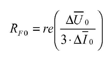
- a faulted phase identification can be made utilizing phase currents and residual voltage measurements according to the following procedure:
- the fault resistance R F (in ohms) can be estimated using equation:
- the logic is based on the fact that fault resistance estimate should not be dependent on the calculated fault distance d with higher value of R F as d becomes corrupted. It should be taken into account only when R F ⁇ ⁇ 100 ohm, i.e. when the fault location calculation is capable of producing reliable values.
- the fault resistance estimate can be used as such to give additional information about the characteristics of the fault; whether it is a low or high ohmic earth fault.
- the fault resistance estimate can also be used for judging the validity of the calculated fault distance estimate.
- the calculated fault distance estimate is typically more accurate when the fault resistance is low, e.g. R F ⁇ ⁇ 100 ohm. It is therefore preferable to judge the validity of calculated fault distance estimate and this can be done reliably utilizing the fault resistance estimation.
- An apparatus may be implemented as a single unit or as two or more separate units that are configured to implement the functionality of the various embodiments.
- the term 'unit' refers generally to a physical or logical entity, such as a physical device or a part thereof or a software routine.
- One or more of these units may reside in the protective relay unit 40, for example.
- An apparatus may be implemented by means of a computer or corresponding digital signal processing equipment provided with suitable software, for example.
- a computer or digital signal processing equipment preferably comprises at least a working memory (RAM) providing storage area for arithmetical operations and a central processing unit (CPU), such as a general-purpose digital signal processor.
- the CPU may comprise a set of registers, an arithmetic logic unit, and a control unit.
- the control unit is controlled by a sequence of program instructions transferred to the CPU from the RAM.
- the control unit may contain a number of microinstructions for basic operations. The implementation of the microinstructions may vary depending on the CPU design.
- the program instructions may be coded by a programming language, which may be a high-level programming language, such as C, Java, etc., or a low-level programming language, such as a machine language, or an assembler.
- the computer may also have an operating system which may provide system services to a computer program written with the program instructions.
- the computer or other apparatus implementing the invention further preferably comprises suitable input means for receiving e.g. measurement and/or control data, which input means thus enable e.g. the monitoring of current and voltage quantities, and output means for outputting e.g. calculation results and/or control data. It is also possible to use a specific integrated circuit or circuits, or corresponding components and devices for implementing the functionality according to any one of the embodiments.
- the invention can be implemented in existing system elements, such as various protective relays or relay arrangements, or by using separate dedicated elements or devices in a centralized or distributed manner.
- Present protective devices for electric systems such as protective relays, typically comprise processors and memory that can be utilized in the functions according to embodiments of the invention.
- all modifications and configurations required for implementing an embodiment of the invention e.g. in existing protective devices may be performed as software routines, which may be implemented as added or updated software routines.
- software can be provided as a computer program product comprising computer program code which, when run on a computer, causes the computer or corresponding arrangement to perform the functionality according to the invention as described above.
- Such a computer program code may be stored or generally embodied on a computer readable medium, such as suitable memory means, e.g. a flash memory or a disc memory from which it is loadable to the unit or units executing the program code.
- suitable memory means e.g. a flash memory or a disc memory from which it is loadable to the unit or units executing the program code.
- a computer program code implementing the invention may be loaded to the unit or units executing the computer program code via a suitable data network, for example, and it may replace or update a possibly existing program code.
Landscapes
- Physics & Mathematics (AREA)
- General Physics & Mathematics (AREA)
- Engineering & Computer Science (AREA)
- Mathematical Physics (AREA)
- Theoretical Computer Science (AREA)
- Emergency Protection Circuit Devices (AREA)
- Locating Faults (AREA)
Abstract
Description
- The invention relates to determining a distance to a phase-to-earth fault on a three-phase electric line of an electric network.
- Distribution networks with their neutral point earthed through a Petersen coil are becoming increasingly popular worldwide. The main advantage of the compensation is the decreased number of customer outages as earth faults become often self-extinguished due to a decreased earth fault current. However, the small fault current poses challenges to the protection of the systems and challenges especially fault location.
- Document "Earth fault distance computation with fundamental frequency signals based on measurements in substation supply bay"; Seppo Hänninen, Matti Lehtonen; VTT Research Notes 2153; Espoo 2002, discloses an example of a method for fault localization of single phase earth faults in Petersen coil compensated networks. The disclosed method utilizes changes of measured quantities (noted as Δ) during the fault. The change during the fault is obtained by changing the impedance of the compensation coil. In practice this means connection or disconnection of the parallel resistor of the compensation coil. The method is based on measurements in a substation supply bay. The fault distance calculation procedure contains the following steps:
Step #1: Detection of the switching on or off of the parallel resistor of the suppression coil. Step #2: Identification of a faulty phase by monitoring the amplitudes of phase-to-earth voltages. Knowledge of the faulted phase is imperative, as it determines the selection of quantities used in the disclosed fault distance calculation. Step #3: The fault current change is assumed to be: Δ I F = 3*ΔI 2,where Δ I 2 is the change in the negative sequence component (measurement after the change (2) minus measurement prior to the change (1) during the fault).Step #4: The voltage change is the change of voltage in the faulty phase, e.g. fault in phase L1: 
Step #5: The fault distance d (in per unit of line length) can be solved: 
where X0, X1, X2 are the zero, positive and negative sequence reactances of the line. -
EP 1304580 describes a fault distance calculation method for compensated networks, which also utilizes changes of measured quantities during the fault. The disclosed method is based on measurement on a feeder bay and the equations used in fault distance calculation are derived from a well known symmetrical component equivalent circuit valid for a single phase earth fault. The fault current change ΔI F is based on the measured residual current and settingY 00-Leitung, which represents the zero-sequence admittance of the protected line, is used for improving the accuracy of fault current change estimate. - Both of the above-described methods have the drawback that all phase-to-earth voltages and all phase currents must be available for the calculation of fault distance. This is often a limitation in practice as these values are not necessarily readily available and might thus require additional measuring arrangements. In addition, the use of phase voltages in the fault distance calculation requires a secure faulted phase identification procedure, otherwise the calculation procedure fails.
- An object of the present invention is thus to provide a method and an apparatus for implementing the method so as to overcome the above problems or at least to alleviate them. The objects of the invention are achieved by a method and an arrangement which are characterized by what is stated in the independent claims. The preferred embodiments of the invention are disclosed in the dependent claims.
- The invention is based on the idea of using a change in a residual voltage of the electric network as an approximation of a change in a voltage in the faulty phase. In addition, the invention is based on modeling the zero sequence circuit of the electric network.
- An advantage of the method and arrangement of the invention is that only the residual voltage and zero sequence current values are needed for the distance calculation instead of all phase-to-earth voltages and all phase currents. The residual voltage and the zero sequence current values are typically readily available and thus the implementation of the invention into existing systems typically does not require additional measuring arrangements.
- In the following the invention will be described in greater detail by means of preferred embodiments with reference to the accompanying drawings, in which
-
Figure 1 is a diagram illustrating an electric network; and -
Figure 2 is an equivalent scheme according to an embodiment. - The application of the invention is not limited to any specific system, but it can be used in connection with various three-phase electric systems to determine a distance to a phase-to-earth fault on a three-phase electric line of an electric network. The electric line can be a feeder, for example, and may be an overhead-line or a cable or a combination thereof. The electric power system in which the invention is implemented can be an electric transmission or distribution network or a component thereof, for example, and may comprise several feeders or sections. Moreover, the use of the invention is not limited to systems employing 50 Hz or 60 Hz fundamental frequencies or to any specific voltage level.
-
Figure 1 is a simplified diagram illustrating an electric network in which the invention can be applied. The figure shows only the components necessary for understanding the invention. The exemplary network can be a medium voltage (e.g. 20 kV) distribution network fed through a substation comprising atransformer 10 and abusbar 20. The illustrated network also comprises electric line outlets, i.e. feeders, of which one 30 is shown separately. Other possible feeders as well as other network parts, except theline 30, are referred to as a 'background network'. The figure also shows aprotective relay unit 40 at the beginning ofline 30, and a point of earth fault F. Theprotective relay unit 40 may be located inside the substation. It should be noted that there may be any number of feeders or other network elements in the network. There may also be several feeding substations. Further, the invention can be utilized with a switching station without atransformer 10, for example. The network is a three-phase network, although, for the sake of clarity, the phases are not shown in the figure. In the exemplary system ofFigure 1 , the functionality of the invention may be located in therelay unit 40, for example. It is also possible that e.g. only some measurements are performed at the location ofunit 40 and the results are then transmitted to another unit or units (not shown in the figures) in another location for further processing. In other words, therelay unit 40 could be a mere measuring unit, while the functionality of the invention, or part of it, could be located in another unit or units. - Current and voltage values that are needed in the following embodiments may be obtained by a suitable measuring arrangement including e.g. current and voltage transducers (not shown in the figures). In most of the existing protection systems, such values are readily available and thus the implementation of the various embodiments does not necessarily require any additional measuring arrangements. The residual voltage of the electric network may be determined from phase voltages or by measuring it from an open delta winding formed by voltage transformers, for example. The zero-sequence current of the
electric line 30 may be determined with a suitable current measuring arrangement at the measuring point such as therelay unit 40. How these values are obtained is of no relevance to the basic idea of the invention and depends on the particular electricity system. A phase-to-earth fault F occurring on the three-phaseelectric line 30 may be detected e.g. by theprotective relay 40 associated with the electricity system. The particular way how such faults are detected is, however, of no relevance to the basic idea of the invention. - According to an embodiment the distance to the fault F from a measuring point, such as the
relay unit 40, may be determined by utilizing changes in a residual voltage of the electric network and in a zero-sequence current of theelectric line 30 at the measuring point during a phase-to-earth fault when a neutral to earth admittance of the electric network outside theelectric line 30 changes from a first value to a second value different from the first value. The change during the fault may be obtained by changing the impedance of a compensation coil, for example. Typically this means the connection or disconnection of a parallel resistor of a compensation coil or a change in the compensation degree of the compensation coil. But the change can be any change in the neutral to earth admittance of the electric network outside theelectric line 30 during the fault, which leads to change in the magnitudes of the voltages and currents. Therefore the invention is not limited to Petersen coil compensated networks. - The event that initiates the distance computation may be an external signal from the compensation equipment indicating e.g. the connection of the parallel resistor or another change. Alternatively, the event that initiates the distance computation may be an internally monitored change, delta, in a resistive current component of a residual current:

where -
I 02 = zero-sequence current of the electric line after the changeU 02 = residual voltage of the system after the change - ϕ2 = angle difference between U02 and
I 02 -
I 01 = zero-sequence current of the electric line prior the changeU 01 = residual voltage of the system prior the change - φ1 = angle difference between
U 01 andI 01 - In other words, the change in the neutral to earth admittance of the electric network from the first value to the second value may be detected by monitoring the resistive current component of the measured residual current. As the ampere value of a possible parallel resistor is known beforehand, a corresponding threshold limit for the change in the resistive current component of the residual current during the fault can be easily defined accordingly. Thus, according to an embodiment, the neutral to earth admittance of the electric network is determined to have changed from the first value to the second value when the resistive current component of the measured residual current changes at least by a predetermined threshold.
-
Figure 2 illustrates an equivalent scheme of a phase-to-earth fault on an electric line. Based on the equivalent scheme the following equation can be written. The change of the quantities refers to a change which results from a change in the neutral to earth admittance outside of the electric line. In the exemplary case of theFigure 2 , this can be accomplished e.g. by connecting admittanceYCC 2 instead of admittanceY CC1 using switches S1 and S2, which thus represents, for instance, the connection or disconnection of a parallel resistor of a possible compensation coil or a change in the compensation degree of the compensation coil.
where - Δ
U 0 = change in the residual voltage (U 0 ) during the fault (volts) - d = fault distance in per unit (p.u.) between the measuring point and fault location
-
Z 0 = zero-sequence impedance of the electric line (ohms) - Δ
I 0 = change in the zero-sequence current (I 0) of the electric line at the measuring point during the fault (amperes) - Δ
I 0Fd = change in the zero-sequence charging current of the electric line (I 0 Fd) during the fault (amperes) -
Z 2 = negative-sequence impedance of the electric line (ohms) - Δ
I f = change in the fault current (I f) during the fault (amperes) -
Z 1 = positive-sequence impedance of the electric line (ohms) - Rf = fault resistance (ohms) in the fault point
- For cables and overhead-lines applies:
-
Z 2 =Z 1 negative sequence impedance equals the positive sequence impedance. - The change in the zero-sequence charging current of the electric line which flows through the zero-sequence impedance during the fault is:

where -
Y 0 Fd = Admittance of the electric line (Siemens), setting - q = Parameter and 0<q≤1; used for estimating how large a portion of the capacitive current of the electric line flows through the zero-sequence impedance during the fault. In case of evenly distributed capacitance, then q equals 0.5. If the electric line has e.g. large branch lines before its midpoint, then the value of q should be below 0.5. If the electric line has e.g. large branch lines after its midpoint, then the value of q should be over 0.5.
- The change in the fault current during the fault is:

- Inserting
equations 2 and 3 intoequation 1, calculating real and imaginary parts and finally solving the equations, gives a second order equation for the fault distance d, which is of form:
where


where - rel0 = real(Δ
I 0 ); - iml0 = imag(Δ
I 0); - reU0 = real(Δ
U 0); - imU0 = imag(Δ
U 0); - reZ0U0Y0 = real(
Z 0. ΔU 0 .Y 0 Fd); - imZ0U0Y0 = imag(
Z 0 . ΔU 0 .Y 0 Fd); - reU0Y0 = real(ΔD
U 0 Y0Fd); - imU0Y0 = imag(Δ
U 0·Y 0 Fd); - reZ1I0 = real(
Z 1· ΔI 0); - imZ1I0 =imag(
Z 1·ΔI 0); - reZ1 U0Y0 = real(
Z 1. ΔU 0 .Y 0Fd); - imZ1 U0Y0 = imag(
Z U 0 .Y 0 Fd ); - reZ010 = real(
Z 0 . ΔI 0); - imZ010 = imag(
Z 0 . ΔI 0). - Thus, the distance d to the phase-to-earth fault from the measuring point may be determined from the above second order equation. According to an embodiment, the solutions for fault distance d are (d1 and d2):

and
- The fault distance may then be determined as follows: d = d1 if d1 is between 0...1 (possibly with some tolerance to cover e.g. possible measurement errors); otherwise d = d2.
- According to an embodiment, a faulted phase identification can be made utilizing phase currents and residual voltage measurements according to the following procedure:
- 1. Calculate
- 2. Calculate:


where
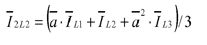

- L1, L2, L3 = phases 1, 2 and 3, respectively
- Δ refers to a change in the quantity due to a change during a fault which results from a change in the neutral to earth admittance outside of the electric line
- 3. Calculate differences:


- 4. Faulted phase is the one with minimum Diff_L-value.
- According to an embodiment, the fault resistance RF (in ohms) can be estimated using equation:
- When


- When


where
R0, R1 = Zero and positive sequence resistance (ohm) of the electric line. - The logic is based on the fact that fault resistance estimate should not be dependent on the calculated fault distance d with higher value of RF as d becomes corrupted. It should be taken into account only when RF ≈ <100 ohm, i.e. when the fault location calculation is capable of producing reliable values. The fault resistance estimate can be used as such to give additional information about the characteristics of the fault; whether it is a low or high ohmic earth fault. The fault resistance estimate can also be used for judging the validity of the calculated fault distance estimate. The calculated fault distance estimate is typically more accurate when the fault resistance is low, e.g. RF ≈ <100 ohm. It is therefore preferable to judge the validity of calculated fault distance estimate and this can be done reliably utilizing the fault resistance estimation.
- An apparatus according to any one of the above embodiments, or a combination thereof, may be implemented as a single unit or as two or more separate units that are configured to implement the functionality of the various embodiments. Here the term 'unit' refers generally to a physical or logical entity, such as a physical device or a part thereof or a software routine. One or more of these units may reside in the
protective relay unit 40, for example. - An apparatus according to any one of the embodiments may be implemented by means of a computer or corresponding digital signal processing equipment provided with suitable software, for example. Such a computer or digital signal processing equipment preferably comprises at least a working memory (RAM) providing storage area for arithmetical operations and a central processing unit (CPU), such as a general-purpose digital signal processor. The CPU may comprise a set of registers, an arithmetic logic unit, and a control unit. The control unit is controlled by a sequence of program instructions transferred to the CPU from the RAM. The control unit may contain a number of microinstructions for basic operations. The implementation of the microinstructions may vary depending on the CPU design. The program instructions may be coded by a programming language, which may be a high-level programming language, such as C, Java, etc., or a low-level programming language, such as a machine language, or an assembler. The computer may also have an operating system which may provide system services to a computer program written with the program instructions. The computer or other apparatus implementing the invention further preferably comprises suitable input means for receiving e.g. measurement and/or control data, which input means thus enable e.g. the monitoring of current and voltage quantities, and output means for outputting e.g. calculation results and/or control data. It is also possible to use a specific integrated circuit or circuits, or corresponding components and devices for implementing the functionality according to any one of the embodiments.
- The invention can be implemented in existing system elements, such as various protective relays or relay arrangements, or by using separate dedicated elements or devices in a centralized or distributed manner. Present protective devices for electric systems, such as protective relays, typically comprise processors and memory that can be utilized in the functions according to embodiments of the invention. Thus, all modifications and configurations required for implementing an embodiment of the invention e.g. in existing protective devices may be performed as software routines, which may be implemented as added or updated software routines. If the functionality of the invention is implemented by software, such software can be provided as a computer program product comprising computer program code which, when run on a computer, causes the computer or corresponding arrangement to perform the functionality according to the invention as described above. Such a computer program code may be stored or generally embodied on a computer readable medium, such as suitable memory means, e.g. a flash memory or a disc memory from which it is loadable to the unit or units executing the program code. In addition, such a computer program code implementing the invention may be loaded to the unit or units executing the computer program code via a suitable data network, for example, and it may replace or update a possibly existing program code.
- It will be obvious to a person skilled in the art that, as the technology advances, the inventive concept can be implemented in various ways. The invention and its embodiments are not limited to the examples described above but may vary within the scope of the claims.
Claims (12)
- A method for determining a distance to a phase-to-earth fault on a three-phase electric line of an electric network, the method comprising:determining, during a phase-to-earth fault (F) on the three-phase electric line (30), values of a residual voltage of the electric network and a zero-sequence current of the electric line at a measuring point (40) when a neutral to earth admittance of the electric network outside the electric line (30) has a first value and when the neutral to earth admittance of the electric network outside the electric line has a second value different from the first value; anddetermining the distance to the phase-to-earth fault (F) from the measuring point (40) on the basis of the determined residual voltage and zero-sequence current values, characterized in that the distance is determined using the following equation:

where
d = fault distance in per unit (p.u.)


whereZ 0 = zero-sequence impedance of the electric lineZ 1 = positive-sequence impedance of the electric lineY 0 Fd = admittance of the electric lineΔU 0 = change in the residual voltage when the neutral to earth admittance of the electric network changes from the first value to the second valueΔI 0 = change in the zero-sequence current when the neutral to earth admittance of the electric network changes from the first value to the second valueq = parameter and 0<q≤1. - A method as claimed in claim 1, characterized in that
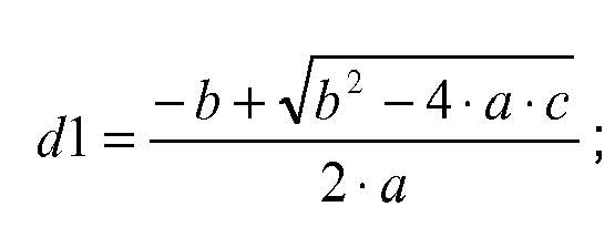
and
wherein the distance d to the phase-to-earth fault (F) from the measuring point (40) is determined as follows: d = d1 if 0≤d1≤1, otherwise d = d2. - A method as claimed in claim 1 or 2, characterized in that the change in the neutral to earth admittance of the electric network outside the electric line (30) from the first value to the second value is detected by monitoring a resistive current component of a residual current of the electric line (30).
- A method as claimed in claim 3, characterized in that the neutral to earth admittance of the electric network outside the electric line (30) is determined to have changed from the first value to the second value when the resistive current component of the residual current of the electric line (30) changes at least by a predetermined threshold.
- A method as claimed in any one of claims 1 to 4, characterized in that q is approximately 0.5.
- A computer program product comprising computer program code, wherein execution of the program code in a computer causes the computer to carry out the steps of the method according to any one of claims 1 to 5.
- An apparatus for determining a distance to a phase-to-earth fault on a three-phase electric line of an electric network, the apparatus comprising:means (40) for determining, during a phase-to-earth fault (F) on the three-phase electric line (30), values of a residual voltage of the electric network and a zero-sequence current of the electric line at a measuring point (40) when a neutral to earth admittance of the electric network outside the electric line (30) has a first value and when the neutral to earth admittance of the electric network outside the electric line has a second value different from the first value; andmeans (40) for determining the distance to the phase-to-earth fault (F) from the measuring point (40) on the basis of the determined residual voltage and zero-sequence current values, characterized in that the means (40) for determining the distance are configured to determine the distance using the following equation:

where
d = fault distance in per unit (p.u.)


whereZ0 = zero-sequence impedance of the electric lineZ 1 = positive-sequence impedance of the electric lineY 0 Fd = admittance of the electric lineΔU 0 = change in the residual voltage when the neutral to earth admittance of the electric network changes from the first value to the second valueΔI 0 = change in the zero-sequence current when the neutral to earth admittance of the electric network changes from the first value to the second valueq = parameter and 0<q≤1. - An apparatus as claimed in claim 7, characterized in that

and
wherein the means (40) for determining the distance are configured to determine the distance d to the phase-to-earth fault from the measuring point as follows: d = d1 if 0≤d1≤1, otherwise d = d2. - An apparatus as claimed in claim 7 or 8, characterized in that the apparatus comprises means (40) for detecting the change in the neutral to earth admittance of the electric network outside the electric line (30) from the first value to the second value by monitoring a resistive current component of a residual current of the electric line (30).
- An apparatus as claimed in claim 9, characterized in that the means (40) for detecting the change in the neutral to earth admittance of the electric network outside the electric line (30) are configured to determine the neutral to earth admittance of the electric network outside the electric line to have changed from the first value to the second value when the resistive current component of the residual current of the electric line (30) changes at least by a predetermined threshold.
- An apparatus as claimed in any one of claims 7 to 10, characterized in that q is approximately 0.5.
- An apparatus as claimed in any one of claims 7 to 11,characterized in that the apparatus comprises a protective relay.
Priority Applications (3)
| Application Number | Priority Date | Filing Date | Title |
|---|---|---|---|
| EP20100167650 EP2402774B1 (en) | 2010-06-29 | 2010-06-29 | Method and apparatus for determining distance to phase-to-earth fault |
| CN201180032942.2A CN102959413B (en) | 2010-06-29 | 2011-06-08 | Method and apparatus for determining distance to phase-to-earth fault |
| PCT/EP2011/059442 WO2012000745A1 (en) | 2010-06-29 | 2011-06-08 | Method and apparatus for determining distance to phase-to-earth fault |
Applications Claiming Priority (1)
| Application Number | Priority Date | Filing Date | Title |
|---|---|---|---|
| EP20100167650 EP2402774B1 (en) | 2010-06-29 | 2010-06-29 | Method and apparatus for determining distance to phase-to-earth fault |
Publications (3)
| Publication Number | Publication Date |
|---|---|
| EP2402774A1 true EP2402774A1 (en) | 2012-01-04 |
| EP2402774A9 EP2402774A9 (en) | 2012-03-07 |
| EP2402774B1 EP2402774B1 (en) | 2013-05-15 |
Family
ID=43299752
Family Applications (1)
| Application Number | Title | Priority Date | Filing Date |
|---|---|---|---|
| EP20100167650 Active EP2402774B1 (en) | 2010-06-29 | 2010-06-29 | Method and apparatus for determining distance to phase-to-earth fault |
Country Status (3)
| Country | Link |
|---|---|
| EP (1) | EP2402774B1 (en) |
| CN (1) | CN102959413B (en) |
| WO (1) | WO2012000745A1 (en) |
Cited By (3)
| Publication number | Priority date | Publication date | Assignee | Title |
|---|---|---|---|---|
| WO2016193529A1 (en) * | 2015-06-03 | 2016-12-08 | Jyväskylän Energia Oy | Method for earth fault protection for a three-phase electrical network |
| CN110146783A (en) * | 2019-05-15 | 2019-08-20 | 上海宏力达信息技术股份有限公司 | A kind of fault section location method |
| CN116613716A (en) * | 2023-07-20 | 2023-08-18 | 国网江西省电力有限公司电力科学研究院 | Voltage sag control method and system based on fault domain |
Families Citing this family (6)
| Publication number | Priority date | Publication date | Assignee | Title |
|---|---|---|---|---|
| CN103245890B (en) * | 2013-05-10 | 2015-11-04 | 国家电网公司 | The line single-phase earth fault single-terminal location method of anti-transition resistance and load current impact |
| EP3570399B1 (en) | 2018-05-18 | 2022-03-16 | ABB Schweiz AG | Method and apparatus for use in earth-fault protection |
| CN112119556B (en) * | 2018-05-18 | 2023-01-24 | Abb瑞士股份有限公司 | Method and apparatus for use in ground fault protection |
| ES2911035T3 (en) | 2018-05-18 | 2022-05-17 | Abb Schweiz Ag | Method and apparatus for use in protection against ground faults |
| CN112152191B (en) * | 2020-09-01 | 2022-05-31 | 国网陕西省电力公司榆林供电公司 | Fault processing method, device and storage medium for distribution line |
| CN119575071B (en) * | 2024-12-02 | 2025-11-18 | 国网湖南省电力有限公司 | A method for fault location and line protection in active distribution networks that is independent of power supply characteristics |
Citations (15)
| Publication number | Priority date | Publication date | Assignee | Title |
|---|---|---|---|---|
| EP0106790A1 (en) * | 1982-09-14 | 1984-04-25 | Asea Ab | Method and apparatus for the localisation of a fault in a three-phase power line |
| DE4026799A1 (en) * | 1990-08-24 | 1992-02-27 | Licentia Gmbh | Selective detection of faults in conductors in high voltage network - by comparing conductor voltages and currents with earth current and star earth voltage |
| EP0665625A2 (en) * | 1994-01-24 | 1995-08-02 | Licentia Patent-Verwaltungs-GmbH | Method for obtaining an impedance value and for processing in a distance protection device |
| DE4429310A1 (en) * | 1994-08-18 | 1996-04-04 | Eberle A Gmbh | Location of earth leakages in three-phase current |
| EP0795944A2 (en) * | 1996-03-12 | 1997-09-17 | AEG ATLAS Schutz- und Leittechnik GmbH | Method for determining the operating parameters of at least one distance relay |
| JP2000227453A (en) * | 1999-02-04 | 2000-08-15 | Kinkei System Corp | Spotting of failure position in electric power transmission system |
| EP1195875A2 (en) * | 2000-09-22 | 2002-04-10 | ABB Substation Automation Oy | Method for identification of a faulting or faulted sending end or feeder branch in an electrical distribution system such as a compensated network |
| EP1304580A2 (en) | 2001-10-19 | 2003-04-23 | Alstom | Method for calculating the fault point distance to a single-pole earth fault within an electric power network |
| DE10143595C1 (en) * | 2001-09-05 | 2003-04-24 | Edc Gmbh | Determining distance of single-pole earth connection on stub line involves measuring phase voltages, conductor currents, computing symmetrical components for different null impedances |
| EP1724597A2 (en) * | 2005-05-17 | 2006-11-22 | ABB Oy | System and method for determining location of phase-to-earth fault |
| EP1739441A1 (en) * | 2005-06-29 | 2007-01-03 | ABB Oy | Method and system for determining location of phase-to-earth fault |
| EP1939638A1 (en) * | 2006-12-29 | 2008-07-02 | ABB Technology AG | System and method for determining location of phase-to-earth fault |
| EP1992954A1 (en) * | 2007-05-18 | 2008-11-19 | ABB Technology AG | Method for determining location of phase-to-earth fault |
| EP2000811A1 (en) * | 2007-05-18 | 2008-12-10 | ABB Technology AG | Method for determining location of phase-to-earth fault |
| EP2006694A1 (en) * | 2007-06-21 | 2008-12-24 | Schneider Electric Industries SAS | Localised insulation control and measurement device for a power grid with insulated neutral |
Family Cites Families (1)
| Publication number | Priority date | Publication date | Assignee | Title |
|---|---|---|---|---|
| DE102007002812A1 (en) * | 2007-01-18 | 2008-07-24 | Robert Bosch Gmbh | Controller for use as parking aid in motor vehicle, comprises microprocessor and interfaces for sensor and for output units, where microprocessor processes and communicates data through interfaces, which are synchronized by ring oscillator |
-
2010
- 2010-06-29 EP EP20100167650 patent/EP2402774B1/en active Active
-
2011
- 2011-06-08 WO PCT/EP2011/059442 patent/WO2012000745A1/en not_active Ceased
- 2011-06-08 CN CN201180032942.2A patent/CN102959413B/en active Active
Patent Citations (15)
| Publication number | Priority date | Publication date | Assignee | Title |
|---|---|---|---|---|
| EP0106790A1 (en) * | 1982-09-14 | 1984-04-25 | Asea Ab | Method and apparatus for the localisation of a fault in a three-phase power line |
| DE4026799A1 (en) * | 1990-08-24 | 1992-02-27 | Licentia Gmbh | Selective detection of faults in conductors in high voltage network - by comparing conductor voltages and currents with earth current and star earth voltage |
| EP0665625A2 (en) * | 1994-01-24 | 1995-08-02 | Licentia Patent-Verwaltungs-GmbH | Method for obtaining an impedance value and for processing in a distance protection device |
| DE4429310A1 (en) * | 1994-08-18 | 1996-04-04 | Eberle A Gmbh | Location of earth leakages in three-phase current |
| EP0795944A2 (en) * | 1996-03-12 | 1997-09-17 | AEG ATLAS Schutz- und Leittechnik GmbH | Method for determining the operating parameters of at least one distance relay |
| JP2000227453A (en) * | 1999-02-04 | 2000-08-15 | Kinkei System Corp | Spotting of failure position in electric power transmission system |
| EP1195875A2 (en) * | 2000-09-22 | 2002-04-10 | ABB Substation Automation Oy | Method for identification of a faulting or faulted sending end or feeder branch in an electrical distribution system such as a compensated network |
| DE10143595C1 (en) * | 2001-09-05 | 2003-04-24 | Edc Gmbh | Determining distance of single-pole earth connection on stub line involves measuring phase voltages, conductor currents, computing symmetrical components for different null impedances |
| EP1304580A2 (en) | 2001-10-19 | 2003-04-23 | Alstom | Method for calculating the fault point distance to a single-pole earth fault within an electric power network |
| EP1724597A2 (en) * | 2005-05-17 | 2006-11-22 | ABB Oy | System and method for determining location of phase-to-earth fault |
| EP1739441A1 (en) * | 2005-06-29 | 2007-01-03 | ABB Oy | Method and system for determining location of phase-to-earth fault |
| EP1939638A1 (en) * | 2006-12-29 | 2008-07-02 | ABB Technology AG | System and method for determining location of phase-to-earth fault |
| EP1992954A1 (en) * | 2007-05-18 | 2008-11-19 | ABB Technology AG | Method for determining location of phase-to-earth fault |
| EP2000811A1 (en) * | 2007-05-18 | 2008-12-10 | ABB Technology AG | Method for determining location of phase-to-earth fault |
| EP2006694A1 (en) * | 2007-06-21 | 2008-12-24 | Schneider Electric Industries SAS | Localised insulation control and measurement device for a power grid with insulated neutral |
Non-Patent Citations (3)
| Title |
|---|
| HÄNNINEN S ET AL: "Earth fault distance computation with fundamental frequency signals based on measurements in substation supply bay", INTERNET CITATION, 2002, XP002454683, Retrieved from the Internet <URL:http://web.archive.org/web/20061230171424/virtual.vtt.fi/inf/pdf/tied otteet/2002/T2153.pdf> [retrieved on 20071008] * |
| NIKANDER A ET AL: "Methods for earth fault identification and distance estimation in a compensated medium voltage distribution network", ENERGY MANAGEMENT AND POWER DELIVERY, 1998. PROCEEDINGS OF EMPD '98. 1 998 INTERNATIONAL CONFERENCE ON SINGAPORE 3-5 MARCH 1998, NEW YORK, NY, USA,IEEE, US, vol. 2, 3 March 1998 (1998-03-03), pages 595 - 600, XP010293689, ISBN: 978-0-7803-4495-2, DOI: 10.1109/EMPD.1998.702754 * |
| NIKANDER A ET AL: "NOVEL ALGORITHMS FOR EARTH FAULT INDICATION BASED ON MONITORING OF SHUNT RESISTANCE OF MV FEEDER AS A PART OF RELAY PROTECTION", INTERNATIONAL CONFERENCE ON DEVELOPMENTS IN POWER SYSTEMPROTECTION, XX, XX, 9 April 2001 (2001-04-09), pages 430 - 433, XP008053503 * |
Cited By (4)
| Publication number | Priority date | Publication date | Assignee | Title |
|---|---|---|---|---|
| WO2016193529A1 (en) * | 2015-06-03 | 2016-12-08 | Jyväskylän Energia Oy | Method for earth fault protection for a three-phase electrical network |
| CN110146783A (en) * | 2019-05-15 | 2019-08-20 | 上海宏力达信息技术股份有限公司 | A kind of fault section location method |
| CN116613716A (en) * | 2023-07-20 | 2023-08-18 | 国网江西省电力有限公司电力科学研究院 | Voltage sag control method and system based on fault domain |
| CN116613716B (en) * | 2023-07-20 | 2023-12-05 | 国网江西省电力有限公司电力科学研究院 | Voltage sag control method and system based on fault domain |
Also Published As
| Publication number | Publication date |
|---|---|
| EP2402774A9 (en) | 2012-03-07 |
| WO2012000745A1 (en) | 2012-01-05 |
| CN102959413A (en) | 2013-03-06 |
| CN102959413B (en) | 2015-04-01 |
| EP2402774B1 (en) | 2013-05-15 |
Similar Documents
| Publication | Publication Date | Title |
|---|---|---|
| EP2113778B1 (en) | System and method for determining location of phase-to-phase fault or three-phase fault | |
| EP2402774B1 (en) | Method and apparatus for determining distance to phase-to-earth fault | |
| EP1992954B1 (en) | Method for determining location of phase-to-earth fault | |
| EP2682768B1 (en) | Method and apparatus for determining the distance to phase-to-earth fault | |
| EP2192416B1 (en) | Method and apparatus for detecting a phase-to-earth fault | |
| EP2000811B1 (en) | Method for determining location of phase-to-earth fault | |
| US7728600B2 (en) | System and method for determining location of phase-to-earth fault | |
| EP1724597B1 (en) | System and method for determining location of phase-to-earth fault | |
| EP2375525B1 (en) | Method and apparatus for differential protection of an electric connection | |
| EP1739441B1 (en) | Method and system for determining location of phase-to-earth fault | |
| EP1870717B1 (en) | System and method for determining phase-to-earth admittances of a three-phase electric line | |
| EP2083278B1 (en) | Method and apparatus for determining location of phase-to-phase fault | |
| EP2490311A9 (en) | Method and apparatus for detecting earth fault | |
| EP2378296B1 (en) | Method and arrangement for determining impedance values |
Legal Events
| Date | Code | Title | Description |
|---|---|---|---|
| AK | Designated contracting states |
Kind code of ref document: A1 Designated state(s): AL AT BE BG CH CY CZ DE DK EE ES FI FR GB GR HR HU IE IS IT LI LT LU LV MC MK MT NL NO PL PT RO SE SI SK SM TR |
|
| AX | Request for extension of the european patent |
Extension state: BA ME RS |
|
| PUAI | Public reference made under article 153(3) epc to a published international application that has entered the european phase |
Free format text: ORIGINAL CODE: 0009012 |
|
| 17P | Request for examination filed |
Effective date: 20120130 |
|
| GRAP | Despatch of communication of intention to grant a patent |
Free format text: ORIGINAL CODE: EPIDOSNIGR1 |
|
| GRAS | Grant fee paid |
Free format text: ORIGINAL CODE: EPIDOSNIGR3 |
|
| GRAA | (expected) grant |
Free format text: ORIGINAL CODE: 0009210 |
|
| AK | Designated contracting states |
Kind code of ref document: B1 Designated state(s): AL AT BE BG CH CY CZ DE DK EE ES FI FR GB GR HR HU IE IS IT LI LT LU LV MC MK MT NL NO PL PT RO SE SI SK SM TR |
|
| REG | Reference to a national code |
Ref country code: GB Ref legal event code: FG4D Ref country code: CH Ref legal event code: EP |
|
| REG | Reference to a national code |
Ref country code: AT Ref legal event code: REF Ref document number: 612413 Country of ref document: AT Kind code of ref document: T Effective date: 20130615 |
|
| REG | Reference to a national code |
Ref country code: IE Ref legal event code: FG4D |
|
| REG | Reference to a national code |
Ref country code: DE Ref legal event code: R096 Ref document number: 602010007039 Country of ref document: DE Effective date: 20130711 |
|
| REG | Reference to a national code |
Ref country code: AT Ref legal event code: MK05 Ref document number: 612413 Country of ref document: AT Kind code of ref document: T Effective date: 20130515 |
|
| REG | Reference to a national code |
Ref country code: LT Ref legal event code: MG4D |
|
| REG | Reference to a national code |
Ref country code: NL Ref legal event code: VDEP Effective date: 20130515 |
|
| PG25 | Lapsed in a contracting state [announced via postgrant information from national office to epo] |
Ref country code: LT Free format text: LAPSE BECAUSE OF FAILURE TO SUBMIT A TRANSLATION OF THE DESCRIPTION OR TO PAY THE FEE WITHIN THE PRESCRIBED TIME-LIMIT Effective date: 20130515 Ref country code: SI Free format text: LAPSE BECAUSE OF FAILURE TO SUBMIT A TRANSLATION OF THE DESCRIPTION OR TO PAY THE FEE WITHIN THE PRESCRIBED TIME-LIMIT Effective date: 20130515 Ref country code: SE Free format text: LAPSE BECAUSE OF FAILURE TO SUBMIT A TRANSLATION OF THE DESCRIPTION OR TO PAY THE FEE WITHIN THE PRESCRIBED TIME-LIMIT Effective date: 20130515 Ref country code: ES Free format text: LAPSE BECAUSE OF FAILURE TO SUBMIT A TRANSLATION OF THE DESCRIPTION OR TO PAY THE FEE WITHIN THE PRESCRIBED TIME-LIMIT Effective date: 20130826 Ref country code: GR Free format text: LAPSE BECAUSE OF FAILURE TO SUBMIT A TRANSLATION OF THE DESCRIPTION OR TO PAY THE FEE WITHIN THE PRESCRIBED TIME-LIMIT Effective date: 20130816 Ref country code: NO Free format text: LAPSE BECAUSE OF FAILURE TO SUBMIT A TRANSLATION OF THE DESCRIPTION OR TO PAY THE FEE WITHIN THE PRESCRIBED TIME-LIMIT Effective date: 20130815 Ref country code: AT Free format text: LAPSE BECAUSE OF FAILURE TO SUBMIT A TRANSLATION OF THE DESCRIPTION OR TO PAY THE FEE WITHIN THE PRESCRIBED TIME-LIMIT Effective date: 20130515 Ref country code: IS Free format text: LAPSE BECAUSE OF FAILURE TO SUBMIT A TRANSLATION OF THE DESCRIPTION OR TO PAY THE FEE WITHIN THE PRESCRIBED TIME-LIMIT Effective date: 20130915 Ref country code: PT Free format text: LAPSE BECAUSE OF FAILURE TO SUBMIT A TRANSLATION OF THE DESCRIPTION OR TO PAY THE FEE WITHIN THE PRESCRIBED TIME-LIMIT Effective date: 20130916 |
|
| PG25 | Lapsed in a contracting state [announced via postgrant information from national office to epo] |
Ref country code: PL Free format text: LAPSE BECAUSE OF FAILURE TO SUBMIT A TRANSLATION OF THE DESCRIPTION OR TO PAY THE FEE WITHIN THE PRESCRIBED TIME-LIMIT Effective date: 20130515 Ref country code: BG Free format text: LAPSE BECAUSE OF FAILURE TO SUBMIT A TRANSLATION OF THE DESCRIPTION OR TO PAY THE FEE WITHIN THE PRESCRIBED TIME-LIMIT Effective date: 20130815 Ref country code: HR Free format text: LAPSE BECAUSE OF FAILURE TO SUBMIT A TRANSLATION OF THE DESCRIPTION OR TO PAY THE FEE WITHIN THE PRESCRIBED TIME-LIMIT Effective date: 20130515 |
|
| PG25 | Lapsed in a contracting state [announced via postgrant information from national office to epo] |
Ref country code: LV Free format text: LAPSE BECAUSE OF FAILURE TO SUBMIT A TRANSLATION OF THE DESCRIPTION OR TO PAY THE FEE WITHIN THE PRESCRIBED TIME-LIMIT Effective date: 20130515 |
|
| PG25 | Lapsed in a contracting state [announced via postgrant information from national office to epo] |
Ref country code: SK Free format text: LAPSE BECAUSE OF FAILURE TO SUBMIT A TRANSLATION OF THE DESCRIPTION OR TO PAY THE FEE WITHIN THE PRESCRIBED TIME-LIMIT Effective date: 20130515 Ref country code: BE Free format text: LAPSE BECAUSE OF FAILURE TO SUBMIT A TRANSLATION OF THE DESCRIPTION OR TO PAY THE FEE WITHIN THE PRESCRIBED TIME-LIMIT Effective date: 20130515 Ref country code: CZ Free format text: LAPSE BECAUSE OF FAILURE TO SUBMIT A TRANSLATION OF THE DESCRIPTION OR TO PAY THE FEE WITHIN THE PRESCRIBED TIME-LIMIT Effective date: 20130515 Ref country code: EE Free format text: LAPSE BECAUSE OF FAILURE TO SUBMIT A TRANSLATION OF THE DESCRIPTION OR TO PAY THE FEE WITHIN THE PRESCRIBED TIME-LIMIT Effective date: 20130515 Ref country code: DK Free format text: LAPSE BECAUSE OF FAILURE TO SUBMIT A TRANSLATION OF THE DESCRIPTION OR TO PAY THE FEE WITHIN THE PRESCRIBED TIME-LIMIT Effective date: 20130515 |
|
| PG25 | Lapsed in a contracting state [announced via postgrant information from national office to epo] |
Ref country code: MC Free format text: LAPSE BECAUSE OF FAILURE TO SUBMIT A TRANSLATION OF THE DESCRIPTION OR TO PAY THE FEE WITHIN THE PRESCRIBED TIME-LIMIT Effective date: 20130515 Ref country code: NL Free format text: LAPSE BECAUSE OF FAILURE TO SUBMIT A TRANSLATION OF THE DESCRIPTION OR TO PAY THE FEE WITHIN THE PRESCRIBED TIME-LIMIT Effective date: 20130515 Ref country code: RO Free format text: LAPSE BECAUSE OF FAILURE TO SUBMIT A TRANSLATION OF THE DESCRIPTION OR TO PAY THE FEE WITHIN THE PRESCRIBED TIME-LIMIT Effective date: 20130515 |
|
| PLBE | No opposition filed within time limit |
Free format text: ORIGINAL CODE: 0009261 |
|
| STAA | Information on the status of an ep patent application or granted ep patent |
Free format text: STATUS: NO OPPOSITION FILED WITHIN TIME LIMIT |
|
| REG | Reference to a national code |
Ref country code: IE Ref legal event code: MM4A |
|
| 26N | No opposition filed |
Effective date: 20140218 |
|
| PG25 | Lapsed in a contracting state [announced via postgrant information from national office to epo] |
Ref country code: IE Free format text: LAPSE BECAUSE OF NON-PAYMENT OF DUE FEES Effective date: 20130629 |
|
| REG | Reference to a national code |
Ref country code: DE Ref legal event code: R097 Ref document number: 602010007039 Country of ref document: DE Effective date: 20140218 |
|
| REG | Reference to a national code |
Ref country code: CH Ref legal event code: PL |
|
| PG25 | Lapsed in a contracting state [announced via postgrant information from national office to epo] |
Ref country code: MT Free format text: LAPSE BECAUSE OF FAILURE TO SUBMIT A TRANSLATION OF THE DESCRIPTION OR TO PAY THE FEE WITHIN THE PRESCRIBED TIME-LIMIT Effective date: 20130515 |
|
| PG25 | Lapsed in a contracting state [announced via postgrant information from national office to epo] |
Ref country code: CH Free format text: LAPSE BECAUSE OF NON-PAYMENT OF DUE FEES Effective date: 20140630 Ref country code: LI Free format text: LAPSE BECAUSE OF NON-PAYMENT OF DUE FEES Effective date: 20140630 |
|
| PG25 | Lapsed in a contracting state [announced via postgrant information from national office to epo] |
Ref country code: SM Free format text: LAPSE BECAUSE OF FAILURE TO SUBMIT A TRANSLATION OF THE DESCRIPTION OR TO PAY THE FEE WITHIN THE PRESCRIBED TIME-LIMIT Effective date: 20130515 |
|
| PG25 | Lapsed in a contracting state [announced via postgrant information from national office to epo] |
Ref country code: CY Free format text: LAPSE BECAUSE OF FAILURE TO SUBMIT A TRANSLATION OF THE DESCRIPTION OR TO PAY THE FEE WITHIN THE PRESCRIBED TIME-LIMIT Effective date: 20130515 Ref country code: TR Free format text: LAPSE BECAUSE OF FAILURE TO SUBMIT A TRANSLATION OF THE DESCRIPTION OR TO PAY THE FEE WITHIN THE PRESCRIBED TIME-LIMIT Effective date: 20130515 |
|
| PG25 | Lapsed in a contracting state [announced via postgrant information from national office to epo] |
Ref country code: HU Free format text: LAPSE BECAUSE OF FAILURE TO SUBMIT A TRANSLATION OF THE DESCRIPTION OR TO PAY THE FEE WITHIN THE PRESCRIBED TIME-LIMIT; INVALID AB INITIO Effective date: 20100629 Ref country code: LU Free format text: LAPSE BECAUSE OF NON-PAYMENT OF DUE FEES Effective date: 20130629 Ref country code: MK Free format text: LAPSE BECAUSE OF FAILURE TO SUBMIT A TRANSLATION OF THE DESCRIPTION OR TO PAY THE FEE WITHIN THE PRESCRIBED TIME-LIMIT Effective date: 20130515 |
|
| REG | Reference to a national code |
Ref country code: FR Ref legal event code: PLFP Year of fee payment: 7 |
|
| REG | Reference to a national code |
Ref country code: DE Ref legal event code: R081 Ref document number: 602010007039 Country of ref document: DE Owner name: ABB SCHWEIZ AG, CH Free format text: FORMER OWNER: ABB TECHNOLOGY AG, ZUERICH, CH |
|
| REG | Reference to a national code |
Ref country code: FR Ref legal event code: PLFP Year of fee payment: 8 |
|
| REG | Reference to a national code |
Ref country code: GB Ref legal event code: 732E Free format text: REGISTERED BETWEEN 20180426 AND 20180502 |
|
| REG | Reference to a national code |
Ref country code: FR Ref legal event code: PLFP Year of fee payment: 9 |
|
| REG | Reference to a national code |
Ref country code: FR Ref legal event code: TP Owner name: ABB SCHWEIZ AG, CH Effective date: 20180912 |
|
| PG25 | Lapsed in a contracting state [announced via postgrant information from national office to epo] |
Ref country code: AL Free format text: LAPSE BECAUSE OF FAILURE TO SUBMIT A TRANSLATION OF THE DESCRIPTION OR TO PAY THE FEE WITHIN THE PRESCRIBED TIME-LIMIT Effective date: 20130515 |
|
| PGFP | Annual fee paid to national office [announced via postgrant information from national office to epo] |
Ref country code: FI Payment date: 20250627 Year of fee payment: 16 |
|
| PGFP | Annual fee paid to national office [announced via postgrant information from national office to epo] |
Ref country code: DE Payment date: 20250618 Year of fee payment: 16 |
|
| PGFP | Annual fee paid to national office [announced via postgrant information from national office to epo] |
Ref country code: GB Payment date: 20250618 Year of fee payment: 16 |
|
| PGFP | Annual fee paid to national office [announced via postgrant information from national office to epo] |
Ref country code: FR Payment date: 20250624 Year of fee payment: 16 |
|
| PGFP | Annual fee paid to national office [announced via postgrant information from national office to epo] |
Ref country code: IT Payment date: 20250624 Year of fee payment: 16 |