EP2402699A2 - Fin and heat exchanger comprising the same - Google Patents
Fin and heat exchanger comprising the same Download PDFInfo
- Publication number
- EP2402699A2 EP2402699A2 EP11003220A EP11003220A EP2402699A2 EP 2402699 A2 EP2402699 A2 EP 2402699A2 EP 11003220 A EP11003220 A EP 11003220A EP 11003220 A EP11003220 A EP 11003220A EP 2402699 A2 EP2402699 A2 EP 2402699A2
- Authority
- EP
- European Patent Office
- Prior art keywords
- fin
- segments
- heat exchanger
- louver
- circular arc
- Prior art date
- Legal status (The legal status is an assumption and is not a legal conclusion. Google has not performed a legal analysis and makes no representation as to the accuracy of the status listed.)
- Withdrawn
Links
Images





Classifications
-
- F—MECHANICAL ENGINEERING; LIGHTING; HEATING; WEAPONS; BLASTING
- F28—HEAT EXCHANGE IN GENERAL
- F28F—DETAILS OF HEAT-EXCHANGE AND HEAT-TRANSFER APPARATUS, OF GENERAL APPLICATION
- F28F1/00—Tubular elements; Assemblies of tubular elements
- F28F1/10—Tubular elements and assemblies thereof with means for increasing heat-transfer area, e.g. with fins, with projections, with recesses
- F28F1/12—Tubular elements and assemblies thereof with means for increasing heat-transfer area, e.g. with fins, with projections, with recesses the means being only outside the tubular element
- F28F1/126—Tubular elements and assemblies thereof with means for increasing heat-transfer area, e.g. with fins, with projections, with recesses the means being only outside the tubular element consisting of zig-zag shaped fins
- F28F1/128—Fins with openings, e.g. louvered fins
-
- F—MECHANICAL ENGINEERING; LIGHTING; HEATING; WEAPONS; BLASTING
- F28—HEAT EXCHANGE IN GENERAL
- F28D—HEAT-EXCHANGE APPARATUS, NOT PROVIDED FOR IN ANOTHER SUBCLASS, IN WHICH THE HEAT-EXCHANGE MEDIA DO NOT COME INTO DIRECT CONTACT
- F28D1/00—Heat-exchange apparatus having stationary conduit assemblies for one heat-exchange medium only, the media being in contact with different sides of the conduit wall, in which the other heat-exchange medium is a large body of fluid, e.g. domestic or motor car radiators
- F28D1/02—Heat-exchange apparatus having stationary conduit assemblies for one heat-exchange medium only, the media being in contact with different sides of the conduit wall, in which the other heat-exchange medium is a large body of fluid, e.g. domestic or motor car radiators with heat-exchange conduits immersed in the body of fluid
- F28D1/04—Heat-exchange apparatus having stationary conduit assemblies for one heat-exchange medium only, the media being in contact with different sides of the conduit wall, in which the other heat-exchange medium is a large body of fluid, e.g. domestic or motor car radiators with heat-exchange conduits immersed in the body of fluid with tubular conduits
- F28D1/053—Heat-exchange apparatus having stationary conduit assemblies for one heat-exchange medium only, the media being in contact with different sides of the conduit wall, in which the other heat-exchange medium is a large body of fluid, e.g. domestic or motor car radiators with heat-exchange conduits immersed in the body of fluid with tubular conduits the conduits being straight
- F28D1/0535—Heat-exchange apparatus having stationary conduit assemblies for one heat-exchange medium only, the media being in contact with different sides of the conduit wall, in which the other heat-exchange medium is a large body of fluid, e.g. domestic or motor car radiators with heat-exchange conduits immersed in the body of fluid with tubular conduits the conduits being straight the conduits having a non-circular cross-section
- F28D1/05366—Assemblies of conduits connected to common headers, e.g. core type radiators
- F28D1/05375—Assemblies of conduits connected to common headers, e.g. core type radiators with particular pattern of flow, e.g. change of flow direction
-
- F—MECHANICAL ENGINEERING; LIGHTING; HEATING; WEAPONS; BLASTING
- F28—HEAT EXCHANGE IN GENERAL
- F28D—HEAT-EXCHANGE APPARATUS, NOT PROVIDED FOR IN ANOTHER SUBCLASS, IN WHICH THE HEAT-EXCHANGE MEDIA DO NOT COME INTO DIRECT CONTACT
- F28D1/00—Heat-exchange apparatus having stationary conduit assemblies for one heat-exchange medium only, the media being in contact with different sides of the conduit wall, in which the other heat-exchange medium is a large body of fluid, e.g. domestic or motor car radiators
- F28D1/02—Heat-exchange apparatus having stationary conduit assemblies for one heat-exchange medium only, the media being in contact with different sides of the conduit wall, in which the other heat-exchange medium is a large body of fluid, e.g. domestic or motor car radiators with heat-exchange conduits immersed in the body of fluid
- F28D2001/0253—Particular components
- F28D2001/026—Cores
- F28D2001/0266—Particular core assemblies, e.g. having different orientations or having different geometric features
Definitions
- the present disclosure generally relates to a fin and a heat exchanger comprising the same, more particularly, to a corrugated fin and a heat exchanger comprising the same.
- a heat exchanger When a heat exchanger is used as an evaporator, a lot of condensate may be accumulated on surfaces of the fins due to structure limitation of the conventional corrugated fin, thus not only influencing the heat transfer performance of the heat exchanger, but also increasing the air resistance of the surface of the heat exchanger and thereby the power consumption of the air blower.
- the conventional fin when the conventional fin is used in an inverted V-shaped or flat plate-shaped heat exchanger, an inclination angle is formed between the surface of the heat exchanger and a horizontal plane.
- the condensate may directly drop into an air pipe below the heat exchanger from the surface of the heat exchanger, so that water leakage may occur in the unit using the heat exchanger and the air pipe may be corroded and bacteria may breed in the corroded air pipe, thus shortening the service life of the unit such as air conditioner and causing damage to human health.
- a corrugated fin used for heat exchanger is provided, the fin has a good water drainage performance such that no condensate drops directly from the surface of a heat exchanger during operation and stoppage. In addition, a good heat exchange performance is ensured and the air side pressure drop is not too large.
- a heat exchanger comprising the corrugated fin is provided.
- a corrugated fin comprising: connection segments each formed with a plurality of louvers; and substantially-circular arc segments connected with the connection segments alternatively in a longitudinal direction such that a plurality of corrugations are formed and substantially-circular arc segments connected with the connection segments alternatively in a longitudinal direction such that a plurality of corrugations are formed and the substantially-circular arc segments form crests and troughs of the corrugations respectively, in which 0 ⁇ H 2 ⁇ ( H 1 -2 R +2 R sin ⁇ )/cos ⁇ , where H 2 is a louver length of the louver, H 1 is a height of the fin, R is a radius of the substantially-circular arc segment, and ⁇ is an inclination angle of the connection segment.
- the corrugated fin according to embodiments of the present disclosure, a good heat exchange performance and a normal air side pressure drop are ensured.
- it may reduce or eliminate the phenomenon that condensate drops from or accumulates on the louvers and the surface of the fins, so that the condensate may flow onto the tubes along the fins and gather into a water collecting pan along the tubes rather than drop into the air pipe. Therefore, no water leakage may occur in the unit using the heat exchanger, and the air pipe may not be corroded and bacteria may not breed in the corroded air pipe, thus lengthening the service life of the unit without causing damage to human health.
- the radius R is greater than or equal about 0.1 mm and less than or equal to about 0.85 mm.
- the inclination angle ⁇ is larger than or equal to about 5°. More particularly, the inclination angle ⁇ is less than or equal to about 20°.
- a fin pitch P of the fin is larger than about 2.5 mm. More particularly, the fin pitch P is larger than or equal to about 2.8 mm and less than or equal to about 7 mm.
- W ⁇ sin ⁇ 0.6 mm in which W is an interval between adjacent louvers, and ⁇ is a louver angle of the louver. More particularly, 0.8 mm ⁇ W x sin ⁇ ⁇ 3.0 mm.
- a heat exchanger comprising: a first header; a second header spaced apart from the first header; a plurality of tubes spaced apart from each other and each connected between the first and second headers in fluid communication therewith; and a plurality of corrugated fins each disposed between adjacent tubes, in which the fin is one according to the first aspect of the present disclosure.
- each tube comprises two straight segments and a bent segment connected between the two straight segments and twisted relative to the two straight segments by a predetermined angle, and no fins are disposed between adjacent the bent segments.
- relative terms such as “longitudinal”, “lateral”, “front”, “rear”, “right”, “left”, “lower”, “upper”, “horizontal”, “vertical”, “above”, “below”, “up”, “top”, “bottom” as well as derivative thereof (e.g., “horizontally”, “downwardly”, “upwardly”, etc.) should be construed to refer to the orientation as then described or as shown in the drawings under discussion. These relative terms are for convenience of description and do not require that the present disclosure be constructed or operated in a particular orientation.
- the corrugated fin 4 comprises substantially-circular arc segments 41 and connection segments 42.
- the substantially-circular arc segments 41 are connected with the connection segments 42 alternatively in a longitudinal direction such that a plurality of corrugations are formed and the substantially-circular arc segments 41 form crests and troughs of the corrugated fin 4 respectively.
- the connection segment 42 can be referred as "fin wall” of a corrugation of the corrugated fin 4 and the substantially-circular arc segment 41 can be referred as "crest” and "trough” of a corrugation of the corrugated fin 4.
- connection segment 42 is formed with a plurality of louvers 43.
- the corrugated fin 4 may be made of aluminum material, however, the present disclosure is not limited to this.
- connection segment 42 is a straight segment. It will be appreciated that the present disclosure is not limited to this, for example, the connection segment 42 may also have an actuate shape.
- corrugated fin 4 A portion of the corrugated fin 4 is shown in Fig. 1 . It will be appreciated that the corrugated fin 4 may have any suitable length in the longitudinal direction (i.e., an up and down direction in Fig. 1 ). In other words, the corrugated fin 4 may have any suitable number of corrugations.
- a plurality of louvers 43 are formed in each connection segment 42, the louver 43 may be formed by cutting and bending a certain portion of the connection segment 42 so as to form a vane 431 and an opening 432.
- a portion of the connection segment 42 is cut and turned over from a surface of the connection segment 42, in which ⁇ is the louver angle (i.e., an inclination angle of the vane 431 with respect to the plane of the connection segment 42, as shown in Fig.
- W is an interval between adjacent louvers 43 (i.e., a straight line length between adjacent louvers 43 in the a transversal direction to the length direction of the louver 43)
- H 2 is a louver length of the louver 43 (i.e., a dimension of the louver 43 in a right and left direction in Fig. 1 )
- S is an vane distance (i.e., a straight line distance between the adjacent vanes 43, as shown in Fig. 2 ).
- a fin pitch P is a spacing between adjacent crest and trough (i.e., adjacent substantially-circular arc segments), in other words, the fin pitch P is a straight line distance between two points with the same phase relationship of the corrugated fin 4 in the longitudinal direction.
- the heat exchanger is used as an evaporator, when the heat exchanger is the flat plate-shaped heat exchanger and inclined with respect to a horizontal direction (as shown in Fig. 9 ) or the heat exchanger is a bent heat exchanger (as shown in Fig. 10 ), during the operation or stoppage, the condensate on the surface of the corrugated fin 4 may directly drop from the surface of the corrugated fin 4.
- the condensate may be accumulated on the surface of the corrugated fin under the following conditions: 1) the smaller the radius R of the substantially-circular arc segment, the greater the surface tension of the condensate is, so that the condensate tends to be accumulated on the substantially-circular arc segment; 2) the smaller the fin pitch P of the fin is, the more condensate tends to accumulate between adjacent connection segments; and 3) the smaller the interval W between adjacent louvers is, the more condensate tends to accumulate between adjacent louvers.
- the heat exchange performance, the air resistance and the accumulated water on the surface of the heat exchanger using the corrugated fin have direct relationship to the louver length H 2 .
- the larger the louver length H 2 of the louver the better the heat exchange performance is and the larger the air resistance is, consequently, more water is accumulated on the fin.
- the inventors of the present disclosure find that: when the louver length H 2 is greater than a length L of the connection segment 42 that is, the louver 43 is extended into the substantially-circular arc segment 41, the increasing trend of the performance of the heat exchanger becomes weak and the increasing trend of the air resistance becomes strong.
- the radius R In order to ensure that no water drops directly from the substantially-circular arc segments 41, the radius R shall be small enough. Considering actual use, there is a limit to decrease the radius R, that is, the radius R can not be decreased infinitely, so that the condensate is unavoidable to accumulate on the substantially-circular arc segments 41. Therefore, it is advantageous to increase the surface tension of water and reduce the weight of the water.
- the water may not drop directly from the substantially-circular arc segment 41 if the radius R is less than or equal to 0.85 mm.
- M ⁇ ⁇ R 2 ⁇ ⁇ 2 / 2 ⁇ ⁇ k in which ⁇ k is the density of the air, R is the radius of the substantially-circular arc segment, and ⁇ is the flowing velocity of the air.
- the adsorption force shall be greater than or equal to the sum of the gravity of water and the pushing force of the air in order to avoid dropping of the condensate from the substantially-circular arc segment 41, that is, the radius R of the substantially-circular arc segment 41 shall be less than or equal to about 0.85 mm. Meanwhile, considering the machinability, the radius R is advantageous to be greater than or equal to about 0.1 mm.
- the adsorption force of the condensate on the substantially-circular arc segment 41 may be greater than the sum of the gravity of the condensate and the pushing force of the air, thus avoiding dropping of the condensate from the substantially-circular arc segment 41. Therefore, the water is prevented from dropping downwards into the air pipe from the substantially-circular arc segment 41.
- connection segments 42 of the corrugated fin 4 if the condensate thereon may not be removed in time, it may drop from the connection segments 42 into the air pipe, so that the water leakage may occur in the unit using the heat exchanger, the air pipe may be corroded and bacteria may breed in the corroded air pipe, thus shortening the service life of the unit and causing damage to human health.
- connection segment 42 In order to ensure that no water drops from the connection segments 42, as shown in Figs. 1 and 3 , the inclination angle ⁇ of the connection segment 42 shall be big enough. Therefore, the condensate will flow downwards along the connection segment 42, and consequently flow into the water collecting pan (not shown) along the tube 3, so that no water is accumulated on and dropped from the connection segment 42. Meanwhile, the fin pitch P shall be large enough.
- the fin pitch P when the fin pitch P is substantially larger than about 2.5 mm, no condensate presents between adjacent connection segments 42. However, the larger the fin pitch P, the lower the performance of the heat exchanger is. Meanwhile, considering machinability, it is advantageous that the fin pitch P is substantially in a range of about 2.8 mm-7 mm.
- the water drainage performance is improved, and it may be reduced or eliminated that the condensate drops into the air pipe from the surface of the heat exchanger using the corrugated fin 4, thus prolonging the life of the unit and reducing the harm of the bacteria.
- the heat exchanger according to an embodiment of the present disclosure comprises a first header 1, a second header 2, a plurality of tubes 3 and a plurality of corrugated fins 4.
- the second header 2 is spaced apart from and substantially parallel to the first header 1.
- the tubes 3 are arranged and spaced apart from each other in a direction parallel to the axial direction of the first and second headers 1 and 2. Two ends of each tube 3 are connected to the first header 1 and the second header 2 respectively to communicate the first header 1 and the second header 2.
- the fins 4 are disposed between adjacent tubes 3, in which the corrugated fin 4 may be one described with reference to the above embodiments.
- the tube 3 may be a flat tube, for example, the shape of the cross section of the tube 3 may be a rectangle, an oblong presenting flat sides interconnecting two round ends, or a flat ellipse.
- the heat exchanger may have a flat plate shape.
- the heat exchanger When used as an evaporator, the heat exchanger is inclined with respect to the horizontal plane, and as shown in Fig. 9 , air blows from an air outlet to the surface of the heat exchanger in a direction A.
- the performance of the heat exchanger may not be influenced, the heat exchanger may not be damaged, and the harm of the bacteria may be avoided.
- the heat exchanger has a bent structure.
- each tube 3 comprises two straight segments 31 and a bent segment 32 connected between the two straight segments 31 and twisted relative to the two straight segments 31 by a predetermined angle, and each fin 4 is only disposed between adjacent straight segments 31, in other words, no fins are disposed between adjacent bent segments 32.
- the heat exchanger having a bent structure is not limited to the above examples, for example, the bent heat exchanger may be formed by two flat plate-shaped heat exchangers connected in series via a connecting pipe and forming a certain intersection angle therebetween.
- the heat exchanger portions on two sides are inclined at a certain angle with respect to the horizontal plane, and as shown in Fig. 10 , air blows from an air outlet to the heat exchanger in a direction A.
- air pipe may not be corroded and bacteria may not breed in the corroded air pipe, thus lengthening the life of the unit such as an air conditioner without causing damage to human health.
Landscapes
- Engineering & Computer Science (AREA)
- Physics & Mathematics (AREA)
- Thermal Sciences (AREA)
- Mechanical Engineering (AREA)
- General Engineering & Computer Science (AREA)
- Geometry (AREA)
- Heat-Exchange Devices With Radiators And Conduit Assemblies (AREA)
Abstract
Description
- The present disclosure generally relates to a fin and a heat exchanger comprising the same, more particularly, to a corrugated fin and a heat exchanger comprising the same.
- When a heat exchanger is used as an evaporator, a lot of condensate may be accumulated on surfaces of the fins due to structure limitation of the conventional corrugated fin, thus not only influencing the heat transfer performance of the heat exchanger, but also increasing the air resistance of the surface of the heat exchanger and thereby the power consumption of the air blower. Particularly, when the conventional fin is used in an inverted V-shaped or flat plate-shaped heat exchanger, an inclination angle is formed between the surface of the heat exchanger and a horizontal plane. Because the condensate is accumulated on the surface of the heat exchanger during operation, the condensate may directly drop into an air pipe below the heat exchanger from the surface of the heat exchanger, so that water leakage may occur in the unit using the heat exchanger and the air pipe may be corroded and bacteria may breed in the corroded air pipe, thus shortening the service life of the unit such as air conditioner and causing damage to human health.
- The present disclosure is directed to solve at least one of the problems existing in the prior art. Accordingly, a corrugated fin used for heat exchanger is provided, the fin has a good water drainage performance such that no condensate drops directly from the surface of a heat exchanger during operation and stoppage. In addition, a good heat exchange performance is ensured and the air side pressure drop is not too large.
- Further, a heat exchanger comprising the corrugated fin is provided.
- According to a first aspect of the present disclosure, a corrugated fin, comprising: connection segments each formed with a plurality of louvers; and substantially-circular arc segments connected with the connection segments alternatively in a longitudinal direction such that a plurality of corrugations are formed and substantially-circular arc segments connected with the connection segments alternatively in a longitudinal direction such that a plurality of corrugations are formed and the substantially-circular arc segments form crests and troughs of the corrugations respectively, in which 0≤H 2≤(H 1-2R+2Rsinβ)/cosβ, where H 2 is a louver length of the louver, H 1 is a height of the fin, R is a radius of the substantially-circular arc segment, and β is an inclination angle of the connection segment.
- With the corrugated fin according to embodiments of the present disclosure, a good heat exchange performance and a normal air side pressure drop are ensured. In addition, it may reduce or eliminate the phenomenon that condensate drops from or accumulates on the louvers and the surface of the fins, so that the condensate may flow onto the tubes along the fins and gather into a water collecting pan along the tubes rather than drop into the air pipe. Therefore, no water leakage may occur in the unit using the heat exchanger, and the air pipe may not be corroded and bacteria may not breed in the corroded air pipe, thus lengthening the service life of the unit without causing damage to human health.
- In some embodiments, the radius R is greater than or equal about 0.1 mm and less than or equal to about 0.85 mm. By setting the radius R in the above range, the accumulated water at the substantially-circular arc segments may be reduced, so that no water may drop from the substantially-circular arc segments.
- Particularly, the inclination angle β is larger than or equal to about 5°. More particularly, the inclination angle β is less than or equal to about 20°.
- In one embodiment, a fin pitch P of the fin is larger than about 2.5 mm. More particularly, the fin pitch P is larger than or equal to about 2.8 mm and less than or equal to about 7 mm.
- In one embodiment, W × sinα≥ 0.6 mm, in which W is an interval between adjacent louvers, and α is a louver angle of the louver. More particularly, 0.8 mm ≤ W x sinα≤ 3.0 mm.
- According to a second aspect of the present disclosure, a heat exchanger is provided, comprising: a first header; a second header spaced apart from the first header; a plurality of tubes spaced apart from each other and each connected between the first and second headers in fluid communication therewith; and a plurality of corrugated fins each disposed between adjacent tubes, in which the fin is one according to the first aspect of the present disclosure.
- Moreover, each tube comprises two straight segments and a bent segment connected between the two straight segments and twisted relative to the two straight segments by a predetermined angle, and no fins are disposed between adjacent the bent segments.
- The above summary of the present disclosure is not intended to describe each disclosed embodiment or every implementation of the present disclosure. The Figures and the detailed description which follow more particularly exemplify illustrative embodiments.
- Additional aspects and advantages of the embodiments of the present disclosure will be given in part in the following descriptions, become apparent in part from the following descriptions, or be learned from the practice of the embodiments of the present disclosure.
- These and other aspects and advantages of the disclosure will become apparent and more readily appreciated from the following descriptions taken in conjunction with the drawings in which:
-
Fig. 1 is schematic view of a portion of the corrugated fin according to an embodiment of the present disclosure; -
Fig. 2 is a sectional view of the fin taken along a line B-B inFig. 1 ; -
Fig. 3 is a principle force diagram of the condensate on the connection segment of the fin shown inFig. 1 ; -
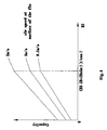
Fig. 4 shows a relationship between a louver length of the louver, a capacity of the fin and an air velocity on the surface of the fin; -
Fig. 5 shows a relationship between a louver length of the louver, an air resistance of the fin and an air velocity on the surface of the fin; -
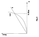
Fig. 6 is a relational graph between the radius of the substantially-circular arc segment, the adsorption force of the condensate and the sum of the gravity of the condensate and the pushing force of the air; -
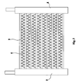
Fig. 7 is a schematic view of the heat exchanger according to an embodiment of the present disclosure; -
Fig. 8 is a perspective view of the heat exchanger according to another embodiment of the present disclosure; -
Fig. 9 is a side view of the heat exchanger shown inFig. 7 in use; and -
Fig. 10 is a side view of the heat exchanger shown inFig. 8 in use. - Reference will be made in detail to embodiments of the present disclosure. The embodiments described herein with reference to the accompany drawings are explanatory and illustrative, which are used to generally understand the present disclosure. The embodiments shall not be construed to limit the present disclosure. The same or similar elements and the elements having same or similar functions are denoted by like reference numerals throughout the descriptions.
- In the description, relative terms such as "longitudinal", "lateral", "front", "rear", "right", "left", "lower", "upper", "horizontal", "vertical", "above", "below", "up", "top", "bottom" as well as derivative thereof (e.g., "horizontally", "downwardly", "upwardly", etc.) should be construed to refer to the orientation as then described or as shown in the drawings under discussion. These relative terms are for convenience of description and do not require that the present disclosure be constructed or operated in a particular orientation.
- Terms concerning attachments, coupling and the like, such as "connected" and "interconnected", refer to a relationship wherein structures are secured or attached to one another either directly or indirectly through intervening structures, as well as both movable or rigid attachments or relationships, unless expressly described otherwise.
- The corrugated fin according to an embodiment of the present disclosure will be described in detail with reference to the drawings.
- As shown in
Figs. 1-2 , the corrugated fin 4 according to an embodiment of the present disclosure comprises substantially-circular arc segments 41 andconnection segments 42. The substantially-circular arc segments 41 are connected with theconnection segments 42 alternatively in a longitudinal direction such that a plurality of corrugations are formed and the substantially-circular arc segments 41 form crests and troughs of the corrugated fin 4 respectively. In other words, theconnection segment 42 can be referred as "fin wall" of a corrugation of the corrugated fin 4 and the substantially-circular arc segment 41 can be referred as "crest" and "trough" of a corrugation of the corrugated fin 4. - Each
connection segment 42 is formed with a plurality oflouvers 43. In some embodiments, for example, the corrugated fin 4 may be made of aluminum material, however, the present disclosure is not limited to this. - In the example shown in
Figs. 1-2 , theconnection segment 42 is a straight segment. It will be appreciated that the present disclosure is not limited to this, for example, theconnection segment 42 may also have an actuate shape. - A portion of the corrugated fin 4 is shown in
Fig. 1 . It will be appreciated that the corrugated fin 4 may have any suitable length in the longitudinal direction (i.e., an up and down direction inFig. 1 ). In other words, the corrugated fin 4 may have any suitable number of corrugations. - As shown in
Figs. 1-2 , in order to improve the heat exchange performance, a plurality oflouvers 43 are formed in eachconnection segment 42, thelouver 43 may be formed by cutting and bending a certain portion of theconnection segment 42 so as to form avane 431 and anopening 432. For example, a portion of theconnection segment 42 is cut and turned over from a surface of theconnection segment 42, in which α is the louver angle (i.e., an inclination angle of thevane 431 with respect to the plane of theconnection segment 42, as shown inFig. 2 ), W is an interval between adjacent louvers 43 (i.e., a straight line length betweenadjacent louvers 43 in the a transversal direction to the length direction of the louver 43), H 2 is a louver length of the louver 43 (i.e., a dimension of thelouver 43 in a right and left direction inFig. 1 ), and S is an vane distance (i.e., a straight line distance between theadjacent vanes 43, as shown inFig. 2 ). A fin pitch P is a spacing between adjacent crest and trough (i.e., adjacent substantially-circular arc segments), in other words, the fin pitch P is a straight line distance between two points with the same phase relationship of the corrugated fin 4 in the longitudinal direction. - If the heat exchanger is used as an evaporator, when the heat exchanger is the flat plate-shaped heat exchanger and inclined with respect to a horizontal direction (as shown in
Fig. 9 ) or the heat exchanger is a bent heat exchanger (as shown inFig. 10 ), during the operation or stoppage, the condensate on the surface of the corrugated fin 4 may directly drop from the surface of the corrugated fin 4. - More particularly, the condensate may be accumulated on the surface of the corrugated fin under the following conditions: 1) the smaller the radius R of the substantially-circular arc segment, the greater the surface tension of the condensate is, so that the condensate tends to be accumulated on the substantially-circular arc segment; 2) the smaller the fin pitch P of the fin is, the more condensate tends to accumulate between adjacent connection segments; and 3) the smaller the interval W between adjacent louvers is, the more condensate tends to accumulate between adjacent louvers.
- The heat exchange performance, the air resistance and the accumulated water on the surface of the heat exchanger using the corrugated fin have direct relationship to the louver length H2. The larger the louver length H 2 of the louver, the better the heat exchange performance is and the larger the air resistance is, consequently, more water is accumulated on the fin.
- As shown in
Figs. 4-5 , the inventors of the present disclosure find that: when the louver length H 2 is greater than a length L of theconnection segment 42 that is, thelouver 43 is extended into the substantially-circular arc segment 41, the increasing trend of the performance of the heat exchanger becomes weak and the increasing trend of the air resistance becomes strong. - It may be obtained from the geometry that: L = (H 1-2R+2Rsinβ)/cosβ.
- Certainly, the larger the louver length H 2, the more water accumulated on the louver is, and the easier the water drops. For this, it is proved by the inventors of the present disclosure through comprehensive considerations and experiments that: it is advantageous to set 0 ≤ H 2 ≤ (H 1-2R+2Rsinβ)/cosβ for preventing water from dropping downwards from the fin, in which H 2 is the louver length, H 1 is the height of the fin, R is the radius of the substantially-circular arc segment, and β is the inclination angle of the connection segment.
- In order to ensure that no water drops directly from the substantially-
circular arc segments 41, the radius R shall be small enough. Considering actual use, there is a limit to decrease the radius R, that is, the radius R can not be decreased infinitely, so that the condensate is unavoidable to accumulate on the substantially-circular arc segments 41. Therefore, it is advantageous to increase the surface tension of water and reduce the weight of the water. - It is confirmed by the inventors that the water may not drop directly from the substantially-
circular arc segment 41 if the radius R is less than or equal to 0.85 mm. - The adsorption force of the condensate to the substantially-
circular arc segment 41 may be calculated by the following formula:
in which F is the adsorption force, σ is the surface tension coefficient, c is the central angle of the substantially-circular arc segment, and R is the radius of the substantially-circular arc segment. - The weight of the condensate on the substantially-circular arc segment may be calculated by the following formula:
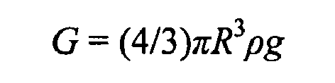
in which ρ is the density of the condensate, g is the acceleration of gravity, and R is the radius of the substantially-circular arc segment. - At the same time, if the air blows downwards, the air will apply a downward pushing force M to the accumulated water on the corrugated fin 4,

in which ρ k is the density of the air, R is the radius of the substantially-circular arc segment, and µ is the flowing velocity of the air. - In order to ensure that no water drops from the substantially-
circular arc segment 41, the following formula shall be satisfied: F ≥ G + M. - As shown in
Fig. 4 , it may be obtained that the adsorption force shall be greater than or equal to the sum of the gravity of water and the pushing force of the air in order to avoid dropping of the condensate from the substantially-circular arc segment 41, that is, the radius R of the substantially-circular arc segment 41 shall be less than or equal to about 0.85 mm. Meanwhile, considering the machinability, the radius R is advantageous to be greater than or equal to about 0.1 mm. - Certainly, under the above conditions, when the air blows upwards, it can be also ensured that no condensate drops from the substantially-
circular arc segment 41. - Therefore, by setting the radius R in a range of about 0.1 mm-about 0.85 mm, the adsorption force of the condensate on the substantially-
circular arc segment 41 may be greater than the sum of the gravity of the condensate and the pushing force of the air, thus avoiding dropping of the condensate from the substantially-circular arc segment 41. Therefore, the water is prevented from dropping downwards into the air pipe from the substantially-circular arc segment 41. - For the
connection segments 42 of the corrugated fin 4, if the condensate thereon may not be removed in time, it may drop from theconnection segments 42 into the air pipe, so that the water leakage may occur in the unit using the heat exchanger, the air pipe may be corroded and bacteria may breed in the corroded air pipe, thus shortening the service life of the unit and causing damage to human health. - In order to ensure that no water drops from the
connection segments 42, as shown inFigs. 1 and3 , the inclination angle β of theconnection segment 42 shall be big enough. Therefore, the condensate will flow downwards along theconnection segment 42, and consequently flow into the water collecting pan (not shown) along thetube 3, so that no water is accumulated on and dropped from theconnection segment 42. Meanwhile, the fin pitch P shall be large enough. - As analyzed by experiments, when the down sliding force of the water on an inclined surface of aluminum alloy fin 4 is greater than the friction force, that is, mg.sinβ > ƒN, in which ƒ is the friction coefficient, and β is the inclination angle of the connection segment, as shown in
Fig. 1 , water may slide downwards. As shown inFig. 3 , according to the force analysis, an equation N = mg.cosβ is obtained, and tanβ > ƒ is obtained by substituting the equation into the formula mg. sinβ > ƒN. It may be obtained by the inventors of the present disclosure that: when the inclination angle β is greater than or equal to about 5°, water starts to flow downwards on the surface of connection segment. Therefore, it is obtained that the inclination angle β shall be greater than or equal to about 5°. Meanwhile, considering machinability, β shall be in a range of about 5°-about 20°. - It is confirmed by the inventors of the present disclosure that: when the fin pitch P is substantially larger than about 2.5 mm, no condensate presents between
adjacent connection segments 42. However, the larger the fin pitch P, the lower the performance of the heat exchanger is. Meanwhile, considering machinability, it is advantageous that the fin pitch P is substantially in a range of about 2.8 mm-7 mm. - The accumulated water between
adjacent louvers 43 is mainly caused by the surface tension of water. If the vane distance S of thelouver 43 is increased, the surface tension of water between theadjacent louvers 43 may be reduced or eliminated, thus decreasing or eliminating the accumulated water between theadjacent louvers 43. It is confirmed by the inventors of the present disclosure that: the surface tension of water between theadjacent louvers 43 may be effectively decreased if the vane distance S = W × sinα ≥ 0.57 mm. For this reason, it is advantageous that W × sinα ≥ 0.6 mm. More particularly, 0.8 mm ≤ W × sinα ≤3.0 mm. - With the corrugated fin 4 according to an embodiment of the present disclosure, the water drainage performance is improved, and it may be reduced or eliminated that the condensate drops into the air pipe from the surface of the heat exchanger using the corrugated fin 4, thus prolonging the life of the unit and reducing the harm of the bacteria.
- The heat exchanger according to an embodiment of the present disclosure will be described below with reference to the drawings.
- As shown in
Fig. 7 , the heat exchanger according to an embodiment of the present disclosure comprises afirst header 1, asecond header 2, a plurality oftubes 3 and a plurality of corrugated fins 4. - The
second header 2 is spaced apart from and substantially parallel to thefirst header 1. Thetubes 3 are arranged and spaced apart from each other in a direction parallel to the axial direction of the first andsecond headers tube 3 are connected to thefirst header 1 and thesecond header 2 respectively to communicate thefirst header 1 and thesecond header 2. The fins 4 are disposed betweenadjacent tubes 3, in which the corrugated fin 4 may be one described with reference to the above embodiments. - In one embodiment, the
tube 3 may be a flat tube, for example, the shape of the cross section of thetube 3 may be a rectangle, an oblong presenting flat sides interconnecting two round ends, or a flat ellipse. - In an example, the heat exchanger may have a flat plate shape. When used as an evaporator, the heat exchanger is inclined with respect to the horizontal plane, and as shown in
Fig. 9 , air blows from an air outlet to the surface of the heat exchanger in a direction A. As described above, because no condensate drops, the performance of the heat exchanger may not be influenced, the heat exchanger may not be damaged, and the harm of the bacteria may be avoided. - As shown in
Fig. 8 , in some embodiments, the heat exchanger has a bent structure. In a specific example, eachtube 3 comprises twostraight segments 31 and abent segment 32 connected between the twostraight segments 31 and twisted relative to the twostraight segments 31 by a predetermined angle, and each fin 4 is only disposed between adjacentstraight segments 31, in other words, no fins are disposed between adjacentbent segments 32. - Certainly, the heat exchanger having a bent structure is not limited to the above examples, for example, the bent heat exchanger may be formed by two flat plate-shaped heat exchangers connected in series via a connecting pipe and forming a certain intersection angle therebetween.
- With the heat exchanger having a bent structure according to an embodiment of the present disclosure, in use, the heat exchanger portions on two sides are inclined at a certain angle with respect to the horizontal plane, and as shown in
Fig. 10 , air blows from an air outlet to the heat exchanger in a direction A. As described above, because no condensate drops, no water leakage may occur, the air pipe may not be corroded and bacteria may not breed in the corroded air pipe, thus lengthening the life of the unit such as an air conditioner without causing damage to human health. - Reference throughout this specification to "an embodiment", "some embodiments", "one embodiment", "an example", "a specific example", or "some examples" means that a particular feature, structure, material, or characteristic described in connection with the embodiment or example is included in at least one embodiment or example of the disclosure. Thus, the appearances of the phrases such as "in some embodiments", "in one embodiment", "in an embodiment", "an example", "a specific example", or "some examples" in various places throughout this specification are not necessarily referring to the same embodiment or example of the disclosure. Furthermore, the particular features, structures, materials, or characteristics may be combined in any suitable manner in one or more embodiments or examples.
- Although explanatory embodiments have been shown and described, it would be appreciated by those skilled in the art that changes, alternatives, and modifications all falling into the scope of the claims and their equivalents may be made in the embodiments without departing from spirit and principles of the disclosure.
Claims (11)
- A corrugated fin, comprising:connection segments each formed with a plurality of louvers; andsubstantially-circular arc segments connected with the connection segments alternatively in a longitudinal direction such that a plurality of corrugations are formed and the substantially-circular arc segments form crests and troughs of the corrugations respectively,wherein 0≤H 2≤(H 1-2R+2Rsinβ)/cosβ
in which H 2 is a louver length of the louver, H 1 is a height of the fin, R is a radius of the substantially-circular arc segment, and β is an inclination angle of the connection segment. - The corrugated fin according to claim 1, wherein the radius R is greater than or equal about 0.1 mm and less than or equal to about 0.85 mm.
- The corrugated fin according to claim 1 or 2, wherein the inclination angle β is larger than or equal to 5°.
- The corrugated fin according to claim 3, wherein the inclination angle β is less than or equal to 20°.
- The corrugated fin according to any one of claims 1-4, wherein W × sinα ≥ 0.6 mm, in which W is an interval between adjacent louvers, and α is a louver angle of the louver.
- The corrugated fin according to claim 1, wherein a fin pitch P of the fin is larger than 2.5 mm.
- The corrugated fin according to claim 6, wherein the fin pitch P is larger than or equal to 2.8 mm and less than or equal to 7 mm.
- The corrugated fin according to claim 6 or 7, wherein W × sinα≥ 0.6 mm, in which W is an interval between adjacent louvers, and α is a louver angle of the louver.
- The corrugated fin according to claim 8, wherein 0.8 mm ≤ W × sinα≤ 3.0 mm.
- A heat exchanger, comprising:a first header;a second header spaced apart from the first header;a plurality of tubes spaced apart from each other and each connected between the first and second headers in fluid communication therewith; anda plurality of corrugated fins each disposed between adjacent tubes, in which each fin is one according to any of claims 1-9.
- The heat exchanger according to claim 10, wherein each tube comprises two straight segments and a bent segment connected between the two straight segments and twisted relative to the two straight segments by a predetermined angle, and no fins are disposed between adjacent the bent segments.
Applications Claiming Priority (1)
| Application Number | Priority Date | Filing Date | Title |
|---|---|---|---|
| CN2010102159283A CN101865625B (en) | 2010-06-29 | 2010-06-29 | Fin and heat exchanger provided with same |
Publications (2)
| Publication Number | Publication Date |
|---|---|
| EP2402699A2 true EP2402699A2 (en) | 2012-01-04 |
| EP2402699A3 EP2402699A3 (en) | 2014-04-09 |
Family
ID=42957443
Family Applications (1)
| Application Number | Title | Priority Date | Filing Date |
|---|---|---|---|
| EP11003220.8A Withdrawn EP2402699A3 (en) | 2010-06-29 | 2011-04-16 | Fin and heat exchanger comprising the same |
Country Status (3)
| Country | Link |
|---|---|
| US (1) | US20110315362A1 (en) |
| EP (1) | EP2402699A3 (en) |
| CN (1) | CN101865625B (en) |
Cited By (1)
| Publication number | Priority date | Publication date | Assignee | Title |
|---|---|---|---|---|
| WO2014124312A1 (en) * | 2013-02-08 | 2014-08-14 | Trane International Inc. | Microchannel heat exchanger |
Families Citing this family (18)
| Publication number | Priority date | Publication date | Assignee | Title |
|---|---|---|---|---|
| US20110048688A1 (en) * | 2009-09-02 | 2011-03-03 | Delphi Technologies, Inc. | Heat Exchanger Assembly |
| CN101846465B (en) * | 2010-04-13 | 2011-11-09 | 三花丹佛斯(杭州)微通道换热器有限公司 | Heat exchanger |
| JP5257485B2 (en) * | 2011-05-13 | 2013-08-07 | ダイキン工業株式会社 | Heat exchanger |
| CN102777980A (en) * | 2012-08-13 | 2012-11-14 | 无锡商业职业技术学院 | Split type high-efficiency long-distance air supply dehumidifier |
| US10113812B2 (en) * | 2013-02-18 | 2018-10-30 | Denso Corporation | Heat exchanger and manufacturing method thereof |
| US9851160B2 (en) | 2013-05-03 | 2017-12-26 | Trane International Inc. | Mounting assembly for heat exchanger coil |
| JP6327271B2 (en) * | 2015-04-17 | 2018-05-23 | 株式会社デンソー | Heat exchanger |
| CN106705498B (en) * | 2015-08-05 | 2019-04-09 | 丹佛斯微通道换热器(嘉兴)有限公司 | Heat exchanger |
| USD910821S1 (en) | 2016-08-26 | 2021-02-16 | Danfoss Micro Channel Heat Exchanger (Jiaxing) Co., Ltd. | Heat exchanger |
| JP2018132247A (en) * | 2017-02-15 | 2018-08-23 | 富士電機株式会社 | vending machine |
| EP3473961B1 (en) | 2017-10-20 | 2020-12-02 | Api Heat Transfer, Inc. | Heat exchanger |
| JP7519919B2 (en) | 2018-10-18 | 2024-07-22 | キャリア コーポレイション | Microchannel Heat Exchanger Tube Support Bracket |
| CN109539634B (en) * | 2018-12-03 | 2020-04-28 | 珠海格力电器股份有限公司 | Micro-channel heat exchanger and air conditioner |
| US12078431B2 (en) | 2020-10-23 | 2024-09-03 | Carrier Corporation | Microchannel heat exchanger for a furnace |
| US12546538B2 (en) | 2020-11-25 | 2026-02-10 | Carrier Corporation | Microchannel heat exchanger tube supported bracket |
| CN215063872U (en) * | 2021-02-07 | 2021-12-07 | 浙江盾安人工环境股份有限公司 | Heat Exchanger and Air Conditioning Equipment |
| JP7802908B2 (en) * | 2021-08-31 | 2026-01-20 | 浙江盾安人工環境股▲ふん▼有限公司 | heat exchanger |
| WO2023237110A1 (en) * | 2022-06-10 | 2023-12-14 | 浙江盾安人工环境股份有限公司 | Fin and heat exchanger provided with same |
Family Cites Families (11)
| Publication number | Priority date | Publication date | Assignee | Title |
|---|---|---|---|---|
| US3265127A (en) * | 1963-10-21 | 1966-08-09 | Ford Motor Co | Heat exchange element |
| JP3043051B2 (en) * | 1990-11-22 | 2000-05-22 | 昭和アルミニウム株式会社 | Heat exchange equipment |
| US5669438A (en) * | 1996-08-30 | 1997-09-23 | General Motors Corporation | Corrugated cooling fin with louvers |
| US6439300B1 (en) * | 1999-12-21 | 2002-08-27 | Delphi Technologies, Inc. | Evaporator with enhanced condensate drainage |
| DE10235038A1 (en) * | 2002-07-31 | 2004-02-12 | Behr Gmbh & Co. | Flat-tube heat exchanger |
| US6874345B2 (en) * | 2003-01-02 | 2005-04-05 | Outokumpu Livernois Engineering Llc | Serpentine fin with extended louvers for heat exchanger and roll forming tool for manufacturing same |
| JP2007178015A (en) * | 2005-12-27 | 2007-07-12 | Showa Denko Kk | Heat exchanger |
| US7921904B2 (en) * | 2007-01-23 | 2011-04-12 | Modine Manufacturing Company | Heat exchanger and method |
| JP2009236470A (en) * | 2008-03-28 | 2009-10-15 | Denso Corp | Heat exchanger |
| CN101694360B (en) * | 2009-09-30 | 2012-03-28 | 天津三电汽车空调有限公司 | Parallel flow heat exchanger and wing band structure thereof |
| CN101738126A (en) * | 2009-12-14 | 2010-06-16 | 三花丹佛斯(杭州)微通道换热器有限公司 | Heat exchanger and fin thereof |
-
2010
- 2010-06-29 CN CN2010102159283A patent/CN101865625B/en active Active
-
2011
- 2011-03-29 US US13/074,104 patent/US20110315362A1/en not_active Abandoned
- 2011-04-16 EP EP11003220.8A patent/EP2402699A3/en not_active Withdrawn
Non-Patent Citations (1)
| Title |
|---|
| None |
Cited By (2)
| Publication number | Priority date | Publication date | Assignee | Title |
|---|---|---|---|---|
| WO2014124312A1 (en) * | 2013-02-08 | 2014-08-14 | Trane International Inc. | Microchannel heat exchanger |
| CN104981674A (en) * | 2013-02-08 | 2015-10-14 | 特灵国际有限公司 | Microchannel heat exchanger |
Also Published As
| Publication number | Publication date |
|---|---|
| US20110315362A1 (en) | 2011-12-29 |
| EP2402699A3 (en) | 2014-04-09 |
| CN101865625B (en) | 2012-09-05 |
| CN101865625A (en) | 2010-10-20 |
Similar Documents
| Publication | Publication Date | Title |
|---|---|---|
| US20110315362A1 (en) | Fin and heat exchanger comprising the same | |
| AU2009261466B2 (en) | Heat exchanger | |
| JP4989979B2 (en) | Heat exchanger | |
| EP2295919B1 (en) | Fin and heat exchanger having the same | |
| EP0881448B1 (en) | Multi-bored flat tube for use in a heat exchanger and heat exchanger including said tubes | |
| US20120227945A1 (en) | Free-draining finned surface architecture for heat exchanger | |
| EP2369285A2 (en) | Heat exchanger | |
| CN106288911B (en) | Fin and radiator comprising same | |
| KR101525749B1 (en) | Drainage structure for corrugated-fin heat exchanger | |
| EP2520893A1 (en) | Heat exchange device | |
| EP1832831A2 (en) | Heat exchanger for stationary air conditioning system with improved water condensate drainage | |
| CN103238038B (en) | Microchannel Heat Exchanger Fins | |
| JP2010019534A (en) | Heat exchanger | |
| CN101995172A (en) | Micro-channel heat exchanger and equipment using same | |
| CN205641693U (en) | Heat exchanger | |
| JPH10141805A (en) | Evaporator | |
| WO2014012284A1 (en) | Filler coupling coil pipe evaporative type condenser | |
| CN101672554B (en) | Heat exchanger capable of improving drainage performance | |
| CN110030865B (en) | Fin and heat exchanger with same | |
| CN107843031B (en) | Microchannel Heat Exchanger | |
| CN211824033U (en) | Heat exchange components and heat exchange systems | |
| CN110094901B (en) | Micro-channel heat exchanger | |
| EP2224198A1 (en) | Fin and tube type heat exchanger | |
| CN212300011U (en) | Heat exchanger and air conditioning unit | |
| CN212457513U (en) | Heat exchanger and air conditioner |
Legal Events
| Date | Code | Title | Description |
|---|---|---|---|
| AK | Designated contracting states |
Kind code of ref document: A2 Designated state(s): AL AT BE BG CH CY CZ DE DK EE ES FI FR GB GR HR HU IE IS IT LI LT LU LV MC MK MT NL NO PL PT RO RS SE SI SK SM TR |
|
| AX | Request for extension of the european patent |
Extension state: BA ME |
|
| PUAI | Public reference made under article 153(3) epc to a published international application that has entered the european phase |
Free format text: ORIGINAL CODE: 0009012 |
|
| RAP1 | Party data changed (applicant data changed or rights of an application transferred) |
Owner name: SANHUA HOLDING GROUP CO., LTD. Owner name: DANFOSS A/S |
|
| PUAL | Search report despatched |
Free format text: ORIGINAL CODE: 0009013 |
|
| AK | Designated contracting states |
Kind code of ref document: A3 Designated state(s): AL AT BE BG CH CY CZ DE DK EE ES FI FR GB GR HR HU IE IS IT LI LT LU LV MC MK MT NL NO PL PT RO RS SE SI SK SM TR |
|
| AX | Request for extension of the european patent |
Extension state: BA ME |
|
| RIC1 | Information provided on ipc code assigned before grant |
Ipc: F28D 1/053 20060101ALI20140228BHEP Ipc: F28F 1/12 20060101AFI20140228BHEP |
|
| 17P | Request for examination filed |
Effective date: 20141004 |
|
| RBV | Designated contracting states (corrected) |
Designated state(s): AL AT BE BG CH CY CZ DE DK EE ES FI FR GB GR HR HU IE IS IT LI LT LU LV MC MK MT NL NO PL PT RO RS SE SI SK SM TR |
|
| RAP1 | Party data changed (applicant data changed or rights of an application transferred) |
Owner name: DANFOSS A/S Owner name: SANHUA (HANGZHOU) MICRO CHANNEL HEAT EXCHANGER CO. |
|
| STAA | Information on the status of an ep patent application or granted ep patent |
Free format text: STATUS: EXAMINATION IS IN PROGRESS |
|
| 17Q | First examination report despatched |
Effective date: 20170310 |
|
| STAA | Information on the status of an ep patent application or granted ep patent |
Free format text: STATUS: THE APPLICATION IS DEEMED TO BE WITHDRAWN |
|
| 18D | Application deemed to be withdrawn |
Effective date: 20180925 |