EP2402609A1 - Pump for dosing fluids - Google Patents
Pump for dosing fluids Download PDFInfo
- Publication number
- EP2402609A1 EP2402609A1 EP11169942A EP11169942A EP2402609A1 EP 2402609 A1 EP2402609 A1 EP 2402609A1 EP 11169942 A EP11169942 A EP 11169942A EP 11169942 A EP11169942 A EP 11169942A EP 2402609 A1 EP2402609 A1 EP 2402609A1
- Authority
- EP
- European Patent Office
- Prior art keywords
- sleeve
- pump
- pumping assembly
- bore
- port
- Prior art date
- Legal status (The legal status is an assumption and is not a legal conclusion. Google has not performed a legal analysis and makes no representation as to the accuracy of the status listed.)
- Granted
Links
Images


Classifications
-
- F—MECHANICAL ENGINEERING; LIGHTING; HEATING; WEAPONS; BLASTING
- F04—POSITIVE - DISPLACEMENT MACHINES FOR LIQUIDS; PUMPS FOR LIQUIDS OR ELASTIC FLUIDS
- F04B—POSITIVE-DISPLACEMENT MACHINES FOR LIQUIDS; PUMPS
- F04B39/00—Component parts, details, or accessories, of pumps or pumping systems specially adapted for elastic fluids, not otherwise provided for in, or of interest apart from, groups F04B25/00 - F04B37/00
- F04B39/12—Casings; Cylinders; Cylinder heads; Fluid connections
- F04B39/126—Cylinder liners
-
- F—MECHANICAL ENGINEERING; LIGHTING; HEATING; WEAPONS; BLASTING
- F04—POSITIVE - DISPLACEMENT MACHINES FOR LIQUIDS; PUMPS FOR LIQUIDS OR ELASTIC FLUIDS
- F04B—POSITIVE-DISPLACEMENT MACHINES FOR LIQUIDS; PUMPS
- F04B53/00—Component parts, details or accessories not provided for in, or of interest apart from, groups F04B1/00 - F04B23/00 or F04B39/00 - F04B47/00
- F04B53/16—Casings; Cylinders; Cylinder liners or heads; Fluid connections
- F04B53/162—Adaptations of cylinders
- F04B53/166—Cylinder liners
-
- F—MECHANICAL ENGINEERING; LIGHTING; HEATING; WEAPONS; BLASTING
- F04—POSITIVE - DISPLACEMENT MACHINES FOR LIQUIDS; PUMPS FOR LIQUIDS OR ELASTIC FLUIDS
- F04B—POSITIVE-DISPLACEMENT MACHINES FOR LIQUIDS; PUMPS
- F04B53/00—Component parts, details or accessories not provided for in, or of interest apart from, groups F04B1/00 - F04B23/00 or F04B39/00 - F04B47/00
- F04B53/16—Casings; Cylinders; Cylinder liners or heads; Fluid connections
- F04B53/162—Adaptations of cylinders
- F04B53/166—Cylinder liners
- F04B53/168—Mounting of cylinder liners in cylinders
-
- F—MECHANICAL ENGINEERING; LIGHTING; HEATING; WEAPONS; BLASTING
- F01—MACHINES OR ENGINES IN GENERAL; ENGINE PLANTS IN GENERAL; STEAM ENGINES
- F01N—GAS-FLOW SILENCERS OR EXHAUST APPARATUS FOR MACHINES OR ENGINES IN GENERAL; GAS-FLOW SILENCERS OR EXHAUST APPARATUS FOR INTERNAL-COMBUSTION ENGINES
- F01N2610/00—Adding substances to exhaust gases
- F01N2610/02—Adding substances to exhaust gases the substance being ammonia or urea
-
- F—MECHANICAL ENGINEERING; LIGHTING; HEATING; WEAPONS; BLASTING
- F01—MACHINES OR ENGINES IN GENERAL; ENGINE PLANTS IN GENERAL; STEAM ENGINES
- F01N—GAS-FLOW SILENCERS OR EXHAUST APPARATUS FOR MACHINES OR ENGINES IN GENERAL; GAS-FLOW SILENCERS OR EXHAUST APPARATUS FOR INTERNAL-COMBUSTION ENGINES
- F01N2610/00—Adding substances to exhaust gases
- F01N2610/14—Arrangements for the supply of substances, e.g. conduits
- F01N2610/1433—Pumps
-
- F—MECHANICAL ENGINEERING; LIGHTING; HEATING; WEAPONS; BLASTING
- F05—INDEXING SCHEMES RELATING TO ENGINES OR PUMPS IN VARIOUS SUBCLASSES OF CLASSES F01-F04
- F05C—INDEXING SCHEME RELATING TO MATERIALS, MATERIAL PROPERTIES OR MATERIAL CHARACTERISTICS FOR MACHINES, ENGINES OR PUMPS OTHER THAN NON-POSITIVE-DISPLACEMENT MACHINES OR ENGINES
- F05C2201/00—Metals
- F05C2201/04—Heavy metals
- F05C2201/0433—Iron group; Ferrous alloys, e.g. steel
- F05C2201/0448—Steel
- F05C2201/0454—Case-hardened steel
-
- Y—GENERAL TAGGING OF NEW TECHNOLOGICAL DEVELOPMENTS; GENERAL TAGGING OF CROSS-SECTIONAL TECHNOLOGIES SPANNING OVER SEVERAL SECTIONS OF THE IPC; TECHNICAL SUBJECTS COVERED BY FORMER USPC CROSS-REFERENCE ART COLLECTIONS [XRACs] AND DIGESTS
- Y10—TECHNICAL SUBJECTS COVERED BY FORMER USPC
- Y10T—TECHNICAL SUBJECTS COVERED BY FORMER US CLASSIFICATION
- Y10T29/00—Metal working
- Y10T29/49—Method of mechanical manufacture
- Y10T29/49229—Prime mover or fluid pump making
- Y10T29/49236—Fluid pump or compressor making
Definitions
- the present invention relates to a pump for dosing fluids and for components for use in such a pump.
- Pumps for dosing fluids are required in a number of technical contexts.
- One such technical context is the dosing of urea solution into the exhaust system of an internal combustion engine to allow a selective catalytic reduction (SCR) catalyst to reduce oxides of nitrogen.
- SCR selective catalytic reduction
- the invention provides a pumping assembly comprising: a pump body with a pump bore, and a sleeve fixed within the pump bore and having a first end, a second end and a sleeve bore; and a plunger adapted to enter the first end of the sleeve and to reciprocate within the sleeve bore, wherein the sleeve has at least one port to allow fluid flow through a wall of the sleeve, and wherein the at least one port is elongated in a direction substantially orthogonal to a direction of reciprocation.
- Such an assembly may be used in a variety of dosing pump structures, for different pump types - such as an armature pump - and for different purposes.
- This arrangement allows for effective manufacture of a pump whose dosing properties may be accurately determined such that pumps made to the same design will have very sim ilar dosing properties - in particular, the start of the dosing process will be well controlled.
- This renders this type of pumping assembly particularly suitable for use in a pump for dosing a chemical reagent into an exhaust pipe of an internal combustion engine, such as a pump used to provide a reducing agent such as urea for selective catalytic reduction.
- said at least one port is formed as an elongate slot - preferably, the long edges of the elongate slot formed with the sleeve bore are substantially orthogonal to an axis of the sleeve bore.
- the pumping assembly comprises two or more ports each formed as an elongate slot, and wherein the long edges of the elongate slot formed with the sleeve bore are substantially parallel to each other.
- one of the two or more ports has a leading edge closer to the second end of the sleeve than the leading edge of any other of the two or more ports, wherein the leading edge of a port is the long edge of the port closer to the second end of the sleeve. If this is the case, only this nearest leading edge is critical to the control of the start of the dosing process, and the other ports need not be formed with the same degree of precision.
- the pump body may comprises a gallery around the at least one port of the sleeve to form a fluid path with the at least one port. This may provide practical advantages, such as the provision of balanced forces around the sleeve.
- the at least one port comprises an annular groove formed on an inner surface of the sleeve. This allows for additional flexibility in manufacture at the assembly stage and provides a more symmetrical, and hence more balanced, arrangement around the plunger.
- both the sleeve and the plunger are formed of a harder material than the pump body.
- the harder material may be a martensitic steel (such as a high nitrogen steel), with the pump body formed of a ferritic steel. This allows only the components whose dimensions are critical for accurate dosing to be formed of harder material, and for other components to be formed from a conventional material which can be machined more easily, although with less exact tolerance.
- the invention provides a sleeve adapted for use as the sleeve of a pumping assembly as described above.
- the invention provides a method of manufacturing a pumping assembly comprising: forming a pump body with a pump bore; forming a sleeve having a first end, a second end and a sleeve bore, and forming at least one port in the sleeve capable of allowing fluid flow through a wall of the sleeve; fixing the sleeve in the pump bore; and mounting a plunger such that it enters the first end of the sleeve and such that it is adapted to reciprocate within the sleeve bore.
- both the sleeve and the plunger are formed from a harder material than the pump body.
- the at least one port is formed by grinding an elongate slot in the sleeve such that the the long edges of the elongate slot formed with the sleeve bore are substantially orthogonal to an axis of the sleeve bore. This allows for effective manufacture of a dimension which is of particular importance in ensuring accurate and reproducible dosing.
- fixing the sleeve to the pump body comprises press fitting the sleeve in the pump body.
- FIG. 1 shows components of a pump in accordance with an embodiment of the invention.
- the pump comprises a plunger 11 adapted to reciprocate in a bore 131 of a pump body 13 with fluid feed ports 15, 16 allowing for passage of fluid into the bore 131 such that passage of fluid through the fluid feed ports 15, 16 is blocked when leading face 19 of the plunger advances sufficiently far into the bore 131.
- Embodiments of the invention may generally be provided for pumps comprising these elements, whatever the overall structure and operating principle of the pump.
- Figure 1 shows an armature pump structure, with the plunger 11 located in an armature 12, for example by press fitting.
- This structure is appropriate for a dosing pump, such as a dosing pump for introducing a chemical agent such as urea into an exhaust system of an internal combustion engine.
- Other elements of the pump are not shown here as their design is not affected by the design of embodiments of the invention.
- An example of an overall pump structure that may readily be adapted by incorporation of an embodiment of the invention as described here is set out in EP 1878920 .
- a diameter of the bore 131 itself is significantly greater than the diameter of the plunger 11, but the leading face 19 of the plunger 11 reciprocates within an additional element, sleeve 14.
- a pumping chamber 191 is thus partly defined by the leading face 19 of the plunger 11 and the interior side walls of the sleeve 14.
- the sleeve 14 is cylindrical, and is fixed within the bore 131 of the pump body 13, for example by press fitting.
- the plunger 11 and the armature 12 thus form one subassembly, and the pump body 13 and the sleeve 14 form another subassembly.
- the sleeve 14 is shown in more detail in Figures 2A to 2D .
- the sleeve 14 contains at least one slot 17, 18 which extends substantially orthogonally to a central axis of the sleeve.
- the slots 17, 18 are straight, and where there are two or more slots these should be parallel to each other.
- the sleeve 14 as shown in Figures 1 and 2 has two slots 17, 18, though the number of slots provided may be determined by the overall structure of the pump and in particular the feed port arrangement that is required.
- the slots 17, 18 each communicate with one of the fluid feed ports 15, 16 of the pump body 13.
- the fluid feed ports 15, 16 may simply be a part of an annular fluid feed chamber, or gallery, formed in the pump body 13.
- the feed ports for the pumping chamber are effectively defined by the slots 17, 18 formed in the sleeve 14.
- the slots 17, 18 should be parallel to each other, one of the slots 17 may be located further in to the pumping chamber 191 than the other slot 18.
- the leading edge 17 will define the point at which fluid starts to flow between the fluid feed ports 15, 16 and the pumping chamber 191 and its disposition will be of particular importance in determining the dosing performance of the resulting pump.
- it will be desirable to control the formation of the slot 17 with sufficient accuracy to control the accuracy of dosing provided by the pump, but it may not be necessary to control the formation of the other slot 18 with the same level of accuracy as this will be of less significance to the performance of the pump.
- Machining of a slot such as slot 17 may be carried out by conventional machining processes with high levels of accuracy, allowing the production of a pump with very well controlled dosing properties.
- slots 17 and 18 may be formed by grinding rather than by drilling (as would be required for a fluid port which is defined by a bore). This also allows for more effective deburring of the port edges than would be possible with a drilled port.
- the sleeve 14 is manufactured from a harder material than the pump body 13, this also allows for precise manufacture, particularly by grinding, to achieve tolerances of the order of 0.005mm on key component dimensions.
- a suitable material is a martensitic steel - a stainless steel such as 440C or high nitrogen steel such as XD15NW or XD15TN - this could also be used for the plunger 11.
- a hard material for these components but not for the armature 12 or the pump body 13 (which may be made of a conventional ferritic steel), allows components that are key for dosing to be manufactured with demanding tolerances, while allowing more complex elements of the pump to be manufactured more easily from a softer material. This allows the process of manufacturing a dosing pump to be simplified without compromise to the effectiveness of the resulting pump.
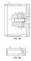
- Figures 4A and 4B show components of a pump in accordance with another embodiment of the invention.
- the embodiment of Figures 4A and 4B largely resembles that of Figure 1 , and the same reference numerals are used for components which are essentially common to the two embodiments.
- the plunger is as for Figure 1 and is not shown in Figure 4A .
- the sleeve 14a contains, instead of elongated slots, an annular groove 47 extending around the inner surface of the sleeve 14a.
- This annular groove acts as a single elongated port extending around a whole inner diameter of the sleeve.
- This groove 47 is then connected to the fluid passage through the pump body by one or more bores 48 in communication with the fluid feed ports 15, 16 in the pump body 13 - in this case, two bores 48 are provided, one at the top and one at the bottom of the sleeve 14a as shown (as best seen in the section shown in Figure 4B ).
- This approach has certain advantages. It offers more flexibility for adjustment at the point of constructing the whole assembly, and it provides a more symmetric and hence balanced port arrangement around the plunger
- Figure 3 shows an example of a pumping system in which embodiments of the present invention may be used effectively.
- This shows a structure for reducing exhaust gas emissions from an internal combustion engine.
- a dosing device is fitted so that it can spray a reducing agent, such as a urea solution, into an exhaust passage.
- the dosing device 1 is mounted within a tubular port 10 of an exhaust passage 4 of an internal combustion engine.
- the dosing device comprises a nozzle body 6 defining an injection bore which is supplied with a solution of a reducing agent 2.
- the tubular port 10 protrudes from, and partially extends into, the exhaust passage 4.
- the dosing device 1 provides a spray of the reducing agent 2 into the exhaust passage 4.
- the dosing device 1 may advantageously be constructed in accordance with embodiments of the invention as described here to achieve reliable dosing consistently between different dosing devices made according to the same design, wherein the design also allows for reliable and effective manufacture.
- Embodiments of the invention may similarly be used for an injector for a common rail diesel fuel injection system, or for other automotive uses such as for an engine pre-heater. This approach can be used to give similar effective dosing in other technical areas, such as medical dosing and manufacture of pharmaceuticals.
Landscapes
- Engineering & Computer Science (AREA)
- Mechanical Engineering (AREA)
- General Engineering & Computer Science (AREA)
- Details Of Reciprocating Pumps (AREA)
- Infusion, Injection, And Reservoir Apparatuses (AREA)
- Exhaust Gas After Treatment (AREA)
Abstract
Description
- The present invention relates to a pump for dosing fluids and for components for use in such a pump.
- Pumps for dosing fluids are required in a number of technical contexts. In certain of these technical contexts, it is desirable for the dose provided by the pump to be controllable with great accuracy, and for one pump to provide very similar dosing outputs to another pump according to the same design. One such technical context is the dosing of urea solution into the exhaust system of an internal combustion engine to allow a selective catalytic reduction (SCR) catalyst to reduce oxides of nitrogen. A dosing system for this purpose is described in
EP 1878920 . - In practice, it is difficult to achieve very high levels of dosing control together with very high levels of consistency in dosing performance between different pumps manufactured according to the same design. It is desirable to address this difficulty without increasing complexity and cost in the manufacturing process.
- Accordingly, the invention provides a pumping assembly comprising: a pump body with a pump bore, and a sleeve fixed within the pump bore and having a first end, a second end and a sleeve bore; and a plunger adapted to enter the first end of the sleeve and to reciprocate within the sleeve bore, wherein the sleeve has at least one port to allow fluid flow through a wall of the sleeve, and wherein the at least one port is elongated in a direction substantially orthogonal to a direction of reciprocation..
- Such an assembly may be used in a variety of dosing pump structures, for different pump types - such as an armature pump - and for different purposes. This arrangement allows for effective manufacture of a pump whose dosing properties may be accurately determined such that pumps made to the same design will have very sim ilar dosing properties - in particular, the start of the dosing process will be well controlled. This renders this type of pumping assembly particularly suitable for use in a pump for dosing a chemical reagent into an exhaust pipe of an internal combustion engine, such as a pump used to provide a reducing agent such as urea for selective catalytic reduction.
- Advantageously, said at least one port is formed as an elongate slot - preferably, the long edges of the elongate slot formed with the sleeve bore are substantially orthogonal to an axis of the sleeve bore. This allows for particularly precise control of the start of the dosing process, and hence of the dosing properties of a pump comprising such a pump assembly.
- Advantageously, the pumping assembly comprises two or more ports each formed as an elongate slot, and wherein the long edges of the elongate slot formed with the sleeve bore are substantially parallel to each other. In such an arrangement, it is desirable if one of the two or more ports has a leading edge closer to the second end of the sleeve than the leading edge of any other of the two or more ports, wherein the leading edge of a port is the long edge of the port closer to the second end of the sleeve. If this is the case, only this nearest leading edge is critical to the control of the start of the dosing process, and the other ports need not be formed with the same degree of precision.
- The pump body may comprises a gallery around the at least one port of the sleeve to form a fluid path with the at least one port. This may provide practical advantages, such as the provision of balanced forces around the sleeve.
- In an alternative arrangement, the at least one port comprises an annular groove formed on an inner surface of the sleeve. This allows for additional flexibility in manufacture at the assembly stage and provides a more symmetrical, and hence more balanced, arrangement around the plunger.
- In one preferred arrangement, both the sleeve and the plunger are formed of a harder material than the pump body. The harder material may be a martensitic steel (such as a high nitrogen steel), with the pump body formed of a ferritic steel. This allows only the components whose dimensions are critical for accurate dosing to be formed of harder material, and for other components to be formed from a conventional material which can be machined more easily, although with less exact tolerance.
- In a further aspect, the invention provides a sleeve adapted for use as the sleeve of a pumping assembly as described above.
- In a still further aspect, the invention provides a method of manufacturing a pumping assembly comprising: forming a pump body with a pump bore; forming a sleeve having a first end, a second end and a sleeve bore, and forming at least one port in the sleeve capable of allowing fluid flow through a wall of the sleeve; fixing the sleeve in the pump bore; and mounting a plunger such that it enters the first end of the sleeve and such that it is adapted to reciprocate within the sleeve bore.
- Preferably both the sleeve and the plunger are formed from a harder material than the pump body. Advantageously, the at least one port is formed by grinding an elongate slot in the sleeve such that the the long edges of the elongate slot formed with the sleeve bore are substantially orthogonal to an axis of the sleeve bore. This allows for effective manufacture of a dimension which is of particular importance in ensuring accurate and reproducible dosing.
- Preferably, fixing the sleeve to the pump body comprises press fitting the sleeve in the pump body.
- Embodiments of the invention will now be described, by way of example, with reference to the accompanying Figures, of which:
-
Figure 1 shows components of a pump according to an embodiment of the invention; -
Figures 2A to 2D show different views of the sleeve ofFigure 1 ; -
Figure 3 shows the use of a pump such as those according to embodiments of the invention for dosing a liquid into the exhaust system of an internal combustion engine; and -
Figure 4A shows components of a pump according to a further embodiment of the invention, and -
Figure 4B shows a sectional view of the sleeve ofFigure 4A from above. -
Figure 1 shows components of a pump in accordance with an embodiment of the invention. The pump comprises aplunger 11 adapted to reciprocate in abore 131 of apump body 13 withfluid feed ports bore 131 such that passage of fluid through thefluid feed ports face 19 of the plunger advances sufficiently far into thebore 131. Embodiments of the invention may generally be provided for pumps comprising these elements, whatever the overall structure and operating principle of the pump. -
Figure 1 shows an armature pump structure, with theplunger 11 located in anarmature 12, for example by press fitting. This structure is appropriate for a dosing pump, such as a dosing pump for introducing a chemical agent such as urea into an exhaust system of an internal combustion engine. Other elements of the pump are not shown here as their design is not affected by the design of embodiments of the invention. An example of an overall pump structure that may readily be adapted by incorporation of an embodiment of the invention as described here is set out inEP 1878920 . - A diameter of the
bore 131 itself is significantly greater than the diameter of theplunger 11, but the leadingface 19 of theplunger 11 reciprocates within an additional element,sleeve 14. Apumping chamber 191 is thus partly defined by the leadingface 19 of theplunger 11 and the interior side walls of thesleeve 14. Thesleeve 14 is cylindrical, and is fixed within thebore 131 of thepump body 13, for example by press fitting. Theplunger 11 and thearmature 12 thus form one subassembly, and thepump body 13 and thesleeve 14 form another subassembly. - The
sleeve 14 is shown in more detail inFigures 2A to 2D . Thesleeve 14 contains at least oneslot slots sleeve 14 as shown inFigures 1 and2 has twoslots slots fluid feed ports pump body 13. In this arrangement, thefluid feed ports pump body 13. In this case, the feed ports for the pumping chamber are effectively defined by theslots sleeve 14. - While the
slots slots 17 may be located further in to thepumping chamber 191 than theother slot 18. In such an arrangement, the leadingedge 17 will define the point at which fluid starts to flow between thefluid feed ports pumping chamber 191 and its disposition will be of particular importance in determining the dosing performance of the resulting pump. In this case, it will be desirable to control the formation of theslot 17 with sufficient accuracy to control the accuracy of dosing provided by the pump, but it may not be necessary to control the formation of theother slot 18 with the same level of accuracy as this will be of less significance to the performance of the pump. - Machining of a slot such as slot 17 (or
slot 18, if required) may be carried out by conventional machining processes with high levels of accuracy, allowing the production of a pump with very well controlled dosing properties. In particular,slots sleeve 14 is manufactured from a harder material than thepump body 13, this also allows for precise manufacture, particularly by grinding, to achieve tolerances of the order of 0.005mm on key component dimensions. A suitable material is a martensitic steel - a stainless steel such as 440C or high nitrogen steel such as XD15NW or XD15TN - this could also be used for theplunger 11. Use of a hard material for these components, but not for thearmature 12 or the pump body 13 (which may be made of a conventional ferritic steel), allows components that are key for dosing to be manufactured with demanding tolerances, while allowing more complex elements of the pump to be manufactured more easily from a softer material. This allows the process of manufacturing a dosing pump to be simplified without compromise to the effectiveness of the resulting pump. -
Figures 4A and 4B show components of a pump in accordance with another embodiment of the invention. The embodiment ofFigures 4A and 4B largely resembles that ofFigure 1 , and the same reference numerals are used for components which are essentially common to the two embodiments. The plunger is as forFigure 1 and is not shown inFigure 4A . - In the embodiment of
Figures 4A and 4B , thesleeve 14a contains, instead of elongated slots, anannular groove 47 extending around the inner surface of thesleeve 14a. This annular groove acts as a single elongated port extending around a whole inner diameter of the sleeve. Thisgroove 47 is then connected to the fluid passage through the pump body by one ormore bores 48 in communication with thefluid feed ports bores 48 are provided, one at the top and one at the bottom of thesleeve 14a as shown (as best seen in the section shown inFigure 4B ). This approach has certain advantages. It offers more flexibility for adjustment at the point of constructing the whole assembly, and it provides a more symmetric and hence balanced port arrangement around the plunger -
Figure 3 shows an example of a pumping system in which embodiments of the present invention may be used effectively. This shows a structure for reducing exhaust gas emissions from an internal combustion engine. A dosing device is fitted so that it can spray a reducing agent, such as a urea solution, into an exhaust passage. The dosing device 1 is mounted within atubular port 10 of anexhaust passage 4 of an internal combustion engine. The dosing device comprises anozzle body 6 defining an injection bore which is supplied with a solution of a reducing agent 2. Thetubular port 10 protrudes from, and partially extends into, theexhaust passage 4. During operation, the dosing device 1 provides a spray of the reducing agent 2 into theexhaust passage 4. - The dosing device 1 may advantageously be constructed in accordance with embodiments of the invention as described here to achieve reliable dosing consistently between different dosing devices made according to the same design, wherein the design also allows for reliable and effective manufacture.
- As indicated previously, this approach may be applied in other embodiments of the invention to other types of pump of the same general structure used for different purposes. Embodiments of the invention may similarly be used for an injector for a common rail diesel fuel injection system, or for other automotive uses such as for an engine pre-heater. This approach can be used to give similar effective dosing in other technical areas, such as medical dosing and manufacture of pharmaceuticals.
Claims (15)
- A pumping assembly comprising:a pump body (13) with a pump bore (131), and a sleeve (14, 14a) fixed within the pump bore (131) and having a first end, a second end and a sleeve bore; anda plunger (11) adapted to enter the first end of the sleeve (14, 14a) and to reciprocate within the sleeve bore;wherein the sleeve (14, 14a) has at least one port (17, 18; 47) to allow fluid flow through a wall of the sleeve (14, 14a), and wherein the at least one port (17, 18; 47) is elongated in a direction substantially orthogonal to a direction of reciprocation..
- A pumping assembly as claimed in claim 1, wherein said at least one port (17, 18) is formed as an elongate slot.
- A pumping assembly as claimed in claim 2, wherein the long edges of the elongate slot formed with the sleeve bore are substantially orthogonal to an axis of the sleeve bore.
- A pumping assembly as claimed in any preceding claim, wherein the pumping assembly comprises two or more ports (17, 18) each formed as an elongate slot, and wherein the long edges of the elongate slot formed with the sleeve bore are substantially parallel to each other.
- A pumping assembly as claimed in claim 4, wherein one of the two or more ports has a leading edge closer to the second end of the sleeve (14) than the leading edge of any other of the two or more ports, wherein the leading edge of a port is the long edge of the port closer to the second end of the sleeve (14).
- A pumping assembly as claimed in any preceding claim, wherein the pump body (13) comprises a gallery around the at least one port of the sleeve (14) to form a fluid path with the at least one port.
- A pumping assembly as claimed in claim 1, wherein the at least one port comprises an annular groove (47) formed on an inner surface of the sleeve (14a).
- A pumping assembly as claimed in any preceding claim, wherein the sleeve (14, 14a) and the plunger (11) are formed of a harder material than the pump body (13).
- A pumping assembly as claimed in any preceding claim, wherein the harder material is a martensitic steel, optionally a high nitrogen steel, wherein the pump body (13) is formed of a ferritic steel.
- A pumping assembly as claimed in any preceding claim, wherein the pumping assembly is comprised within an armature pump.
- A pumping assembly as claimed in any preceding claim, wherein the pumping assembly is comprised within a pump for dosing a chemical reagent into an exhaust pipe of an internal combustion engine.
- A sleeve adapted for use as the sleeve (14, 14a) of a pumping assembly as claimed in any of claims 1 to 11.
- A method of manufacturing a pumping assembly comprising:forming a pump body (13) with a pump bore (131);forming a sleeve (14, 14a) having a first end, a second end and a sleeve bore, and forming at least one port in the sleeve capable of allowing fluid flow through a wall of the sleeve (14, 14a);fixing the sleeve in the pump bore; andmounting a plunger (11) such that it enters the first end of the sleeve (14, 14a) and such that it is adapted to reciprocate within the sleeve bore wherein the at least one port is elongated in a direction substantially orthogonal to a direction of reciprocation.
- A method as claimed in claim 13, wherein fixing the sleeve (14, 14a) to the pump body (13) comprises press fitting the sleeve (14, 14a) in the pump body (13).
- A method as claimed in claim 13 or claim 14, in which the sleeve (14, 14a) and the plunger (11) are formed from a harder material than the pump body (13).
Priority Applications (1)
| Application Number | Priority Date | Filing Date | Title |
|---|---|---|---|
| EP11169942.7A EP2402609B1 (en) | 2010-07-02 | 2011-06-15 | Pump for dosing fluids |
Applications Claiming Priority (2)
| Application Number | Priority Date | Filing Date | Title |
|---|---|---|---|
| EP10168274A EP2402608A1 (en) | 2010-07-02 | 2010-07-02 | Pump for dosing fluids |
| EP11169942.7A EP2402609B1 (en) | 2010-07-02 | 2011-06-15 | Pump for dosing fluids |
Publications (2)
| Publication Number | Publication Date |
|---|---|
| EP2402609A1 true EP2402609A1 (en) | 2012-01-04 |
| EP2402609B1 EP2402609B1 (en) | 2018-12-19 |
Family
ID=42670630
Family Applications (2)
| Application Number | Title | Priority Date | Filing Date |
|---|---|---|---|
| EP10168274A Withdrawn EP2402608A1 (en) | 2010-07-02 | 2010-07-02 | Pump for dosing fluids |
| EP11169942.7A Active EP2402609B1 (en) | 2010-07-02 | 2011-06-15 | Pump for dosing fluids |
Family Applications Before (1)
| Application Number | Title | Priority Date | Filing Date |
|---|---|---|---|
| EP10168274A Withdrawn EP2402608A1 (en) | 2010-07-02 | 2010-07-02 | Pump for dosing fluids |
Country Status (3)
| Country | Link |
|---|---|
| US (1) | US9617987B2 (en) |
| EP (2) | EP2402608A1 (en) |
| JP (1) | JP5456724B2 (en) |
Cited By (1)
| Publication number | Priority date | Publication date | Assignee | Title |
|---|---|---|---|---|
| CN111911273A (en) * | 2020-08-20 | 2020-11-10 | 安徽江淮汽车集团股份有限公司 | Method and system for monitoring urea consumption of vehicle |
Families Citing this family (2)
| Publication number | Priority date | Publication date | Assignee | Title |
|---|---|---|---|---|
| CN102689165A (en) * | 2012-06-21 | 2012-09-26 | 张家口中地装备探矿工程机械有限公司 | Method and device for machining elongated opposite key grooves |
| CN110714819A (en) * | 2019-10-31 | 2020-01-21 | 中自环保科技股份有限公司 | SCR (Selective catalytic reduction) purification system for ship engine tail gas |
Citations (10)
| Publication number | Priority date | Publication date | Assignee | Title |
|---|---|---|---|---|
| US2222823A (en) * | 1938-03-10 | 1940-11-26 | Fluidpoise Mfg Company Inc | Pumping apparatus |
| US4424012A (en) * | 1981-10-09 | 1984-01-03 | Inotek-Westmoreland Venture | In-line fluid pump and shuttle valve therefor |
| US4808092A (en) * | 1986-01-08 | 1989-02-28 | Saphirwerk Industrieprodukte | Precision reciprocating metering pump |
| GB2281359A (en) * | 1993-08-31 | 1995-03-01 | Bosch Gmbh Robert | Reciprocating pump having a housing block and at least one reciprocating pump element |
| WO1996001946A1 (en) * | 1994-07-12 | 1996-01-25 | Andrzej Osiecki | Hydrostatic axial piston machine |
| US5860798A (en) * | 1995-03-03 | 1999-01-19 | Cryopump Ag | Pump for pumping a fluid comprising a liquefied gas and apparatus having a pump |
| US6283733B1 (en) * | 1997-07-30 | 2001-09-04 | Robert Bosch Gmbh | Piston pump for a vehicle brake system |
| US6334762B1 (en) * | 1997-07-30 | 2002-01-01 | Robert Bosch Gmbh | Piston pump including an easily produced flow conduit |
| EP1878920A1 (en) | 2006-07-12 | 2008-01-16 | Delphi Technologies, Inc. | Reagent dosing pump |
| US20100046862A1 (en) * | 2006-11-07 | 2010-02-25 | BSH Bosch und Siemens Hausgeräte GmbH | Linear compressor and gas thrust bearing therefor |
Family Cites Families (20)
| Publication number | Priority date | Publication date | Assignee | Title |
|---|---|---|---|---|
| US1735117A (en) * | 1928-02-04 | 1929-11-12 | Omar C Kiger | Relief valve for pressure pumps |
| US2569233A (en) * | 1947-09-17 | 1951-09-25 | Gen Motors Corp | Fuel injection pump |
| US2869945A (en) * | 1955-11-17 | 1959-01-20 | Virdean R Mattingly | Pump |
| US3838943A (en) * | 1968-12-23 | 1974-10-01 | Borg Warner | Pump apparatus |
| US3614944A (en) * | 1969-09-11 | 1971-10-26 | Ord Systems Ltd | Engine apparatus |
| US3885895A (en) * | 1971-09-18 | 1975-05-27 | Bosch Gmbh Robert | Fuel injection pump for internal combustion engines |
| DE3136749A1 (en) * | 1981-09-16 | 1983-03-31 | Robert Bosch Gmbh, 7000 Stuttgart | FUEL INJECTION PUMP FOR INTERNAL COMBUSTION ENGINES |
| DE3504789A1 (en) * | 1985-02-13 | 1986-08-14 | Webasto-Werk W. Baier GmbH & Co, 8035 Gauting | ELECTROMAGNETICALLY ACTUATED PISTON PUMP |
| DE3600341A1 (en) | 1986-01-08 | 1987-07-09 | Saphirwerk Ind Prod | Fine-dosing pump for liquids, in particular for use in HPLC technology |
| US4758135A (en) * | 1986-12-30 | 1988-07-19 | Weatherford U.S., Inc. | Pump head |
| DE3729938C1 (en) * | 1987-09-07 | 1989-03-30 | Eberspaecher J | Device for conveying and preheating fuel sensitive to cold |
| JPH03168355A (en) * | 1989-11-29 | 1991-07-22 | Zexel Corp | Fuel injection pump |
| US5372115A (en) * | 1991-09-10 | 1994-12-13 | Detroit Diesel Corporation | Fuel system for methanol fueled diesel cycle internal combustion engine |
| DE19806265C5 (en) * | 1998-02-16 | 2004-07-22 | Siemens Ag | dosing |
| JPH11303709A (en) * | 1998-04-24 | 1999-11-02 | Sumitomo Electric Ind Ltd | Fuel injection pump |
| EP1348864A4 (en) * | 2001-01-05 | 2005-03-16 | Hitachi Ltd | HIGH PRESSURE FUEL SUPPLY PUMP |
| KR100461232B1 (en) | 2001-12-03 | 2004-12-14 | 삼성광주전자 주식회사 | Apparatus for compressing fluid |
| DE10231216A1 (en) * | 2002-07-11 | 2004-01-22 | Hydraulik-Ring Gmbh | Device for exhaust gas aftertreatment of motor vehicles, in particular diesel motor vehicles |
| US7467749B2 (en) * | 2004-04-26 | 2008-12-23 | Tenneco Automotive Operating Company Inc. | Methods and apparatus for injecting atomized reagent |
| US8287256B2 (en) * | 2007-11-01 | 2012-10-16 | Caterpillar Inc. | Valve assembly |
-
2010
- 2010-07-02 EP EP10168274A patent/EP2402608A1/en not_active Withdrawn
-
2011
- 2011-06-15 EP EP11169942.7A patent/EP2402609B1/en active Active
- 2011-06-24 US US13/168,353 patent/US9617987B2/en active Active
- 2011-06-28 JP JP2011143071A patent/JP5456724B2/en not_active Expired - Fee Related
Patent Citations (10)
| Publication number | Priority date | Publication date | Assignee | Title |
|---|---|---|---|---|
| US2222823A (en) * | 1938-03-10 | 1940-11-26 | Fluidpoise Mfg Company Inc | Pumping apparatus |
| US4424012A (en) * | 1981-10-09 | 1984-01-03 | Inotek-Westmoreland Venture | In-line fluid pump and shuttle valve therefor |
| US4808092A (en) * | 1986-01-08 | 1989-02-28 | Saphirwerk Industrieprodukte | Precision reciprocating metering pump |
| GB2281359A (en) * | 1993-08-31 | 1995-03-01 | Bosch Gmbh Robert | Reciprocating pump having a housing block and at least one reciprocating pump element |
| WO1996001946A1 (en) * | 1994-07-12 | 1996-01-25 | Andrzej Osiecki | Hydrostatic axial piston machine |
| US5860798A (en) * | 1995-03-03 | 1999-01-19 | Cryopump Ag | Pump for pumping a fluid comprising a liquefied gas and apparatus having a pump |
| US6283733B1 (en) * | 1997-07-30 | 2001-09-04 | Robert Bosch Gmbh | Piston pump for a vehicle brake system |
| US6334762B1 (en) * | 1997-07-30 | 2002-01-01 | Robert Bosch Gmbh | Piston pump including an easily produced flow conduit |
| EP1878920A1 (en) | 2006-07-12 | 2008-01-16 | Delphi Technologies, Inc. | Reagent dosing pump |
| US20100046862A1 (en) * | 2006-11-07 | 2010-02-25 | BSH Bosch und Siemens Hausgeräte GmbH | Linear compressor and gas thrust bearing therefor |
Cited By (2)
| Publication number | Priority date | Publication date | Assignee | Title |
|---|---|---|---|---|
| CN111911273A (en) * | 2020-08-20 | 2020-11-10 | 安徽江淮汽车集团股份有限公司 | Method and system for monitoring urea consumption of vehicle |
| CN111911273B (en) * | 2020-08-20 | 2021-06-08 | 安徽江淮汽车集团股份有限公司 | Method and system for monitoring urea consumption of vehicle |
Also Published As
| Publication number | Publication date |
|---|---|
| US20120003110A1 (en) | 2012-01-05 |
| US9617987B2 (en) | 2017-04-11 |
| EP2402609B1 (en) | 2018-12-19 |
| EP2402608A1 (en) | 2012-01-04 |
| JP5456724B2 (en) | 2014-04-02 |
| JP2012013086A (en) | 2012-01-19 |
Similar Documents
| Publication | Publication Date | Title |
|---|---|---|
| KR102194371B1 (en) | High-pressure fuel pump for a fuel injection system | |
| EP1811165B1 (en) | Common rail having orifice | |
| EP2061956B1 (en) | Exhaust-gas aftertreatment system | |
| US9617987B2 (en) | Pump for dosing fluids | |
| JP4442567B2 (en) | Common rail | |
| US20060008363A1 (en) | High-pressure pump, in particular for a fuel injection system of an internal combustion engine | |
| JP5984838B2 (en) | Injection valve | |
| CN116113760B (en) | Fuel distributor rail for an injection system and injection system for a mixed compression, externally ignited internal combustion engine | |
| US8302888B2 (en) | Fuel injector | |
| US20120012681A1 (en) | Fuel injector having balanced and guided plunger | |
| EP1333173B1 (en) | Accumulator distribution type fuel injection pump | |
| JP4774126B2 (en) | Armature for solenoid actuator | |
| EP2333307A1 (en) | Fuel injection valve for internal combustion engine and method of manufacturing the same | |
| JP2009257216A (en) | Fuel injection valve | |
| EP2726717B1 (en) | Pump assembly | |
| EP2725227B1 (en) | Pump assembly | |
| RU2415295C2 (en) | Method for making injection hole in injector | |
| US11680514B2 (en) | Liquid injection nozzle | |
| WO2016208138A1 (en) | Fuel injection nozzle | |
| EP3443216B1 (en) | Swirl injector plunger | |
| EP1445476A1 (en) | Valve needle and metering device comprising same | |
| CN104074702A (en) | Reducing agent metering pump for tail gas purification aftertreatment system of internal combustion engine and assembly method thereof | |
| CN117167171A (en) | Electronically controlled fuel injector assembly structure | |
| WO2016206914A1 (en) | Injection device for a liquid reductant | |
| CN105927438B (en) | Oil inlet and oil return mounting structure has the Electrocontrolled high-pressure fuel injector of high-freedom degree |
Legal Events
| Date | Code | Title | Description |
|---|---|---|---|
| AK | Designated contracting states |
Kind code of ref document: A1 Designated state(s): AL AT BE BG CH CY CZ DE DK EE ES FI FR GB GR HR HU IE IS IT LI LT LU LV MC MK MT NL NO PL PT RO RS SE SI SK SM TR |
|
| AX | Request for extension of the european patent |
Extension state: BA ME |
|
| PUAI | Public reference made under article 153(3) epc to a published international application that has entered the european phase |
Free format text: ORIGINAL CODE: 0009012 |
|
| 17P | Request for examination filed |
Effective date: 20120704 |
|
| RAP1 | Party data changed (applicant data changed or rights of an application transferred) |
Owner name: DELPHI INTERNATIONAL OPERATIONS LUXEMBOURG S.A.R.L |
|
| STAA | Information on the status of an ep patent application or granted ep patent |
Free format text: STATUS: EXAMINATION IS IN PROGRESS |
|
| 17Q | First examination report despatched |
Effective date: 20170905 |
|
| GRAP | Despatch of communication of intention to grant a patent |
Free format text: ORIGINAL CODE: EPIDOSNIGR1 |
|
| STAA | Information on the status of an ep patent application or granted ep patent |
Free format text: STATUS: GRANT OF PATENT IS INTENDED |
|
| INTG | Intention to grant announced |
Effective date: 20180706 |
|
| GRAS | Grant fee paid |
Free format text: ORIGINAL CODE: EPIDOSNIGR3 |
|
| GRAA | (expected) grant |
Free format text: ORIGINAL CODE: 0009210 |
|
| STAA | Information on the status of an ep patent application or granted ep patent |
Free format text: STATUS: THE PATENT HAS BEEN GRANTED |
|
| AK | Designated contracting states |
Kind code of ref document: B1 Designated state(s): AL AT BE BG CH CY CZ DE DK EE ES FI FR GB GR HR HU IE IS IT LI LT LU LV MC MK MT NL NO PL PT RO RS SE SI SK SM TR |
|
| AX | Request for extension of the european patent |
Extension state: BA ME |
|
| REG | Reference to a national code |
Ref country code: GB Ref legal event code: FG4D |
|
| REG | Reference to a national code |
Ref country code: CH Ref legal event code: EP |
|
| REG | Reference to a national code |
Ref country code: DE Ref legal event code: R096 Ref document number: 602011054907 Country of ref document: DE |
|
| REG | Reference to a national code |
Ref country code: IE Ref legal event code: FG4D |
|
| REG | Reference to a national code |
Ref country code: AT Ref legal event code: REF Ref document number: 1079015 Country of ref document: AT Kind code of ref document: T Effective date: 20190115 |
|
| REG | Reference to a national code |
Ref country code: DE Ref legal event code: R081 Ref document number: 602011054907 Country of ref document: DE Owner name: DELPHI TECHNOLOGIES IP LIMITED, BB Free format text: FORMER OWNER: DELPHI INTERNATIONAL OPERATIONS LUXEMBOURG S.A.R.L., BASCHARAGE, LU |
|
| REG | Reference to a national code |
Ref country code: GB Ref legal event code: 732E Free format text: REGISTERED BETWEEN 20190222 AND 20190227 |
|
| REG | Reference to a national code |
Ref country code: NL Ref legal event code: MP Effective date: 20181219 |
|
| PG25 | Lapsed in a contracting state [announced via postgrant information from national office to epo] |
Ref country code: HR Free format text: LAPSE BECAUSE OF FAILURE TO SUBMIT A TRANSLATION OF THE DESCRIPTION OR TO PAY THE FEE WITHIN THE PRESCRIBED TIME-LIMIT Effective date: 20181219 Ref country code: LT Free format text: LAPSE BECAUSE OF FAILURE TO SUBMIT A TRANSLATION OF THE DESCRIPTION OR TO PAY THE FEE WITHIN THE PRESCRIBED TIME-LIMIT Effective date: 20181219 Ref country code: NO Free format text: LAPSE BECAUSE OF FAILURE TO SUBMIT A TRANSLATION OF THE DESCRIPTION OR TO PAY THE FEE WITHIN THE PRESCRIBED TIME-LIMIT Effective date: 20190319 Ref country code: BG Free format text: LAPSE BECAUSE OF FAILURE TO SUBMIT A TRANSLATION OF THE DESCRIPTION OR TO PAY THE FEE WITHIN THE PRESCRIBED TIME-LIMIT Effective date: 20190319 Ref country code: FI Free format text: LAPSE BECAUSE OF FAILURE TO SUBMIT A TRANSLATION OF THE DESCRIPTION OR TO PAY THE FEE WITHIN THE PRESCRIBED TIME-LIMIT Effective date: 20181219 Ref country code: LV Free format text: LAPSE BECAUSE OF FAILURE TO SUBMIT A TRANSLATION OF THE DESCRIPTION OR TO PAY THE FEE WITHIN THE PRESCRIBED TIME-LIMIT Effective date: 20181219 |
|
| REG | Reference to a national code |
Ref country code: LT Ref legal event code: MG4D |
|
| REG | Reference to a national code |
Ref country code: AT Ref legal event code: MK05 Ref document number: 1079015 Country of ref document: AT Kind code of ref document: T Effective date: 20181219 |
|
| PG25 | Lapsed in a contracting state [announced via postgrant information from national office to epo] |
Ref country code: RS Free format text: LAPSE BECAUSE OF FAILURE TO SUBMIT A TRANSLATION OF THE DESCRIPTION OR TO PAY THE FEE WITHIN THE PRESCRIBED TIME-LIMIT Effective date: 20181219 Ref country code: SE Free format text: LAPSE BECAUSE OF FAILURE TO SUBMIT A TRANSLATION OF THE DESCRIPTION OR TO PAY THE FEE WITHIN THE PRESCRIBED TIME-LIMIT Effective date: 20181219 Ref country code: GR Free format text: LAPSE BECAUSE OF FAILURE TO SUBMIT A TRANSLATION OF THE DESCRIPTION OR TO PAY THE FEE WITHIN THE PRESCRIBED TIME-LIMIT Effective date: 20190320 Ref country code: AL Free format text: LAPSE BECAUSE OF FAILURE TO SUBMIT A TRANSLATION OF THE DESCRIPTION OR TO PAY THE FEE WITHIN THE PRESCRIBED TIME-LIMIT Effective date: 20181219 |
|
| PG25 | Lapsed in a contracting state [announced via postgrant information from national office to epo] |
Ref country code: NL Free format text: LAPSE BECAUSE OF FAILURE TO SUBMIT A TRANSLATION OF THE DESCRIPTION OR TO PAY THE FEE WITHIN THE PRESCRIBED TIME-LIMIT Effective date: 20181219 |
|
| PG25 | Lapsed in a contracting state [announced via postgrant information from national office to epo] |
Ref country code: PL Free format text: LAPSE BECAUSE OF FAILURE TO SUBMIT A TRANSLATION OF THE DESCRIPTION OR TO PAY THE FEE WITHIN THE PRESCRIBED TIME-LIMIT Effective date: 20181219 Ref country code: CZ Free format text: LAPSE BECAUSE OF FAILURE TO SUBMIT A TRANSLATION OF THE DESCRIPTION OR TO PAY THE FEE WITHIN THE PRESCRIBED TIME-LIMIT Effective date: 20181219 Ref country code: IT Free format text: LAPSE BECAUSE OF FAILURE TO SUBMIT A TRANSLATION OF THE DESCRIPTION OR TO PAY THE FEE WITHIN THE PRESCRIBED TIME-LIMIT Effective date: 20181219 Ref country code: ES Free format text: LAPSE BECAUSE OF FAILURE TO SUBMIT A TRANSLATION OF THE DESCRIPTION OR TO PAY THE FEE WITHIN THE PRESCRIBED TIME-LIMIT Effective date: 20181219 Ref country code: PT Free format text: LAPSE BECAUSE OF FAILURE TO SUBMIT A TRANSLATION OF THE DESCRIPTION OR TO PAY THE FEE WITHIN THE PRESCRIBED TIME-LIMIT Effective date: 20190419 |
|
| PG25 | Lapsed in a contracting state [announced via postgrant information from national office to epo] |
Ref country code: IS Free format text: LAPSE BECAUSE OF FAILURE TO SUBMIT A TRANSLATION OF THE DESCRIPTION OR TO PAY THE FEE WITHIN THE PRESCRIBED TIME-LIMIT Effective date: 20190419 Ref country code: RO Free format text: LAPSE BECAUSE OF FAILURE TO SUBMIT A TRANSLATION OF THE DESCRIPTION OR TO PAY THE FEE WITHIN THE PRESCRIBED TIME-LIMIT Effective date: 20181219 Ref country code: EE Free format text: LAPSE BECAUSE OF FAILURE TO SUBMIT A TRANSLATION OF THE DESCRIPTION OR TO PAY THE FEE WITHIN THE PRESCRIBED TIME-LIMIT Effective date: 20181219 Ref country code: SM Free format text: LAPSE BECAUSE OF FAILURE TO SUBMIT A TRANSLATION OF THE DESCRIPTION OR TO PAY THE FEE WITHIN THE PRESCRIBED TIME-LIMIT Effective date: 20181219 Ref country code: SK Free format text: LAPSE BECAUSE OF FAILURE TO SUBMIT A TRANSLATION OF THE DESCRIPTION OR TO PAY THE FEE WITHIN THE PRESCRIBED TIME-LIMIT Effective date: 20181219 |
|
| REG | Reference to a national code |
Ref country code: DE Ref legal event code: R097 Ref document number: 602011054907 Country of ref document: DE |
|
| PLBE | No opposition filed within time limit |
Free format text: ORIGINAL CODE: 0009261 |
|
| STAA | Information on the status of an ep patent application or granted ep patent |
Free format text: STATUS: NO OPPOSITION FILED WITHIN TIME LIMIT |
|
| PG25 | Lapsed in a contracting state [announced via postgrant information from national office to epo] |
Ref country code: AT Free format text: LAPSE BECAUSE OF FAILURE TO SUBMIT A TRANSLATION OF THE DESCRIPTION OR TO PAY THE FEE WITHIN THE PRESCRIBED TIME-LIMIT Effective date: 20181219 Ref country code: DK Free format text: LAPSE BECAUSE OF FAILURE TO SUBMIT A TRANSLATION OF THE DESCRIPTION OR TO PAY THE FEE WITHIN THE PRESCRIBED TIME-LIMIT Effective date: 20181219 |
|
| 26N | No opposition filed |
Effective date: 20190920 |
|
| PG25 | Lapsed in a contracting state [announced via postgrant information from national office to epo] |
Ref country code: MC Free format text: LAPSE BECAUSE OF FAILURE TO SUBMIT A TRANSLATION OF THE DESCRIPTION OR TO PAY THE FEE WITHIN THE PRESCRIBED TIME-LIMIT Effective date: 20181219 |
|
| REG | Reference to a national code |
Ref country code: CH Ref legal event code: PL |
|
| PG25 | Lapsed in a contracting state [announced via postgrant information from national office to epo] |
Ref country code: SI Free format text: LAPSE BECAUSE OF FAILURE TO SUBMIT A TRANSLATION OF THE DESCRIPTION OR TO PAY THE FEE WITHIN THE PRESCRIBED TIME-LIMIT Effective date: 20181219 |
|
| REG | Reference to a national code |
Ref country code: BE Ref legal event code: MM Effective date: 20190630 |
|
| PG25 | Lapsed in a contracting state [announced via postgrant information from national office to epo] |
Ref country code: TR Free format text: LAPSE BECAUSE OF FAILURE TO SUBMIT A TRANSLATION OF THE DESCRIPTION OR TO PAY THE FEE WITHIN THE PRESCRIBED TIME-LIMIT Effective date: 20181219 |
|
| PG25 | Lapsed in a contracting state [announced via postgrant information from national office to epo] |
Ref country code: IE Free format text: LAPSE BECAUSE OF NON-PAYMENT OF DUE FEES Effective date: 20190615 |
|
| PG25 | Lapsed in a contracting state [announced via postgrant information from national office to epo] |
Ref country code: LU Free format text: LAPSE BECAUSE OF NON-PAYMENT OF DUE FEES Effective date: 20190615 Ref country code: BE Free format text: LAPSE BECAUSE OF NON-PAYMENT OF DUE FEES Effective date: 20190630 Ref country code: LI Free format text: LAPSE BECAUSE OF NON-PAYMENT OF DUE FEES Effective date: 20190630 Ref country code: CH Free format text: LAPSE BECAUSE OF NON-PAYMENT OF DUE FEES Effective date: 20190630 |
|
| PGFP | Annual fee paid to national office [announced via postgrant information from national office to epo] |
Ref country code: FR Payment date: 20200625 Year of fee payment: 10 |
|
| PGFP | Annual fee paid to national office [announced via postgrant information from national office to epo] |
Ref country code: GB Payment date: 20200629 Year of fee payment: 10 |
|
| PG25 | Lapsed in a contracting state [announced via postgrant information from national office to epo] |
Ref country code: CY Free format text: LAPSE BECAUSE OF FAILURE TO SUBMIT A TRANSLATION OF THE DESCRIPTION OR TO PAY THE FEE WITHIN THE PRESCRIBED TIME-LIMIT Effective date: 20181219 |
|
| PG25 | Lapsed in a contracting state [announced via postgrant information from national office to epo] |
Ref country code: MT Free format text: LAPSE BECAUSE OF FAILURE TO SUBMIT A TRANSLATION OF THE DESCRIPTION OR TO PAY THE FEE WITHIN THE PRESCRIBED TIME-LIMIT Effective date: 20181219 Ref country code: HU Free format text: LAPSE BECAUSE OF FAILURE TO SUBMIT A TRANSLATION OF THE DESCRIPTION OR TO PAY THE FEE WITHIN THE PRESCRIBED TIME-LIMIT; INVALID AB INITIO Effective date: 20110615 |
|
| GBPC | Gb: european patent ceased through non-payment of renewal fee |
Effective date: 20210615 |
|
| PG25 | Lapsed in a contracting state [announced via postgrant information from national office to epo] |
Ref country code: GB Free format text: LAPSE BECAUSE OF NON-PAYMENT OF DUE FEES Effective date: 20210615 |
|
| PG25 | Lapsed in a contracting state [announced via postgrant information from national office to epo] |
Ref country code: FR Free format text: LAPSE BECAUSE OF NON-PAYMENT OF DUE FEES Effective date: 20210630 |
|
| PG25 | Lapsed in a contracting state [announced via postgrant information from national office to epo] |
Ref country code: MK Free format text: LAPSE BECAUSE OF FAILURE TO SUBMIT A TRANSLATION OF THE DESCRIPTION OR TO PAY THE FEE WITHIN THE PRESCRIBED TIME-LIMIT Effective date: 20181219 |
|
| P01 | Opt-out of the competence of the unified patent court (upc) registered |
Effective date: 20230327 |
|
| REG | Reference to a national code |
Ref country code: DE Ref legal event code: R081 Ref document number: 602011054907 Country of ref document: DE Owner name: PHINIA DELPHI LUXEMBOURG SARL, LU Free format text: FORMER OWNER: DELPHI TECHNOLOGIES IP LIMITED, ST. MICHAEL, BB |
|
| PGFP | Annual fee paid to national office [announced via postgrant information from national office to epo] |
Ref country code: DE Payment date: 20250509 Year of fee payment: 15 |