EP2402557A2 - Turbine rotor assembly - Google Patents
Turbine rotor assembly Download PDFInfo
- Publication number
- EP2402557A2 EP2402557A2 EP11168586A EP11168586A EP2402557A2 EP 2402557 A2 EP2402557 A2 EP 2402557A2 EP 11168586 A EP11168586 A EP 11168586A EP 11168586 A EP11168586 A EP 11168586A EP 2402557 A2 EP2402557 A2 EP 2402557A2
- Authority
- EP
- European Patent Office
- Prior art keywords
- turbine rotor
- radially inner
- insulating material
- thermally insulating
- turbine
- Prior art date
- Legal status (The legal status is an assumption and is not a legal conclusion. Google has not performed a legal analysis and makes no representation as to the accuracy of the status listed.)
- Granted
Links
- 239000011810 insulating material Substances 0.000 claims abstract description 70
- 239000002826 coolant Substances 0.000 claims description 23
- 239000004965 Silica aerogel Substances 0.000 claims description 12
- VYPSYNLAJGMNEJ-UHFFFAOYSA-N Silicium dioxide Chemical compound O=[Si]=O VYPSYNLAJGMNEJ-UHFFFAOYSA-N 0.000 claims description 12
- 230000003014 reinforcing effect Effects 0.000 claims description 9
- 238000001816 cooling Methods 0.000 claims description 8
- 239000004964 aerogel Substances 0.000 claims description 7
- 239000003365 glass fiber Substances 0.000 claims description 3
- 230000008646 thermal stress Effects 0.000 abstract description 4
- 239000007789 gas Substances 0.000 description 13
- 238000011144 upstream manufacturing Methods 0.000 description 8
- 239000000463 material Substances 0.000 description 3
- 241000218642 Abies Species 0.000 description 2
- 239000002184 metal Substances 0.000 description 2
- 230000001141 propulsive effect Effects 0.000 description 2
- 108010047370 pyrogel Proteins 0.000 description 2
- 230000003068 static effect Effects 0.000 description 2
- 241000183024 Populus tremula Species 0.000 description 1
- 230000001133 acceleration Effects 0.000 description 1
- 239000012530 fluid Substances 0.000 description 1
- 239000000446 fuel Substances 0.000 description 1
- 239000007788 liquid Substances 0.000 description 1
- 239000007779 soft material Substances 0.000 description 1
- 239000007787 solid Substances 0.000 description 1
- 230000035882 stress Effects 0.000 description 1
Images


Classifications
-
- F—MECHANICAL ENGINEERING; LIGHTING; HEATING; WEAPONS; BLASTING
- F01—MACHINES OR ENGINES IN GENERAL; ENGINE PLANTS IN GENERAL; STEAM ENGINES
- F01D—NON-POSITIVE DISPLACEMENT MACHINES OR ENGINES, e.g. STEAM TURBINES
- F01D5/00—Blades; Blade-carrying members; Heating, heat-insulating, cooling or antivibration means on the blades or the members
- F01D5/02—Blade-carrying members, e.g. rotors
- F01D5/08—Heating, heat-insulating or cooling means
- F01D5/081—Cooling fluid being directed on the side of the rotor disc or at the roots of the blades
- F01D5/082—Cooling fluid being directed on the side of the rotor disc or at the roots of the blades on the side of the rotor disc
-
- F—MECHANICAL ENGINEERING; LIGHTING; HEATING; WEAPONS; BLASTING
- F01—MACHINES OR ENGINES IN GENERAL; ENGINE PLANTS IN GENERAL; STEAM ENGINES
- F01D—NON-POSITIVE DISPLACEMENT MACHINES OR ENGINES, e.g. STEAM TURBINES
- F01D5/00—Blades; Blade-carrying members; Heating, heat-insulating, cooling or antivibration means on the blades or the members
- F01D5/02—Blade-carrying members, e.g. rotors
- F01D5/08—Heating, heat-insulating or cooling means
- F01D5/081—Cooling fluid being directed on the side of the rotor disc or at the roots of the blades
-
- F—MECHANICAL ENGINEERING; LIGHTING; HEATING; WEAPONS; BLASTING
- F01—MACHINES OR ENGINES IN GENERAL; ENGINE PLANTS IN GENERAL; STEAM ENGINES
- F01D—NON-POSITIVE DISPLACEMENT MACHINES OR ENGINES, e.g. STEAM TURBINES
- F01D5/00—Blades; Blade-carrying members; Heating, heat-insulating, cooling or antivibration means on the blades or the members
- F01D5/30—Fixing blades to rotors; Blade roots ; Blade spacers
- F01D5/3092—Protective layers between blade root and rotor disc surfaces, e.g. anti-friction layers
-
- F—MECHANICAL ENGINEERING; LIGHTING; HEATING; WEAPONS; BLASTING
- F05—INDEXING SCHEMES RELATING TO ENGINES OR PUMPS IN VARIOUS SUBCLASSES OF CLASSES F01-F04
- F05D—INDEXING SCHEME FOR ASPECTS RELATING TO NON-POSITIVE-DISPLACEMENT MACHINES OR ENGINES, GAS-TURBINES OR JET-PROPULSION PLANTS
- F05D2260/00—Function
- F05D2260/20—Heat transfer, e.g. cooling
- F05D2260/221—Improvement of heat transfer
- F05D2260/2214—Improvement of heat transfer by increasing the heat transfer surface
- F05D2260/22141—Improvement of heat transfer by increasing the heat transfer surface using fins or ribs
Definitions
- the present invention relates to a turbine rotor assembly and in particular to a turbine rotor assembly for a gas turbine engine.
- a turbine rotor assembly comprises a turbine rotor carrying a plurality of circumferentially spaced radially outwardly extending turbine rotor blades.
- the turbine rotor has a rim and a plurality of circumferentially spaced slots provided in the rim of the turbine rotor.
- Each turbine rotor blade has a root and the root of each turbine rotor blade is arranged in a corresponding one of the slots in the rim of the turbine rotor.
- the roots of the turbine rotor blades are generally firtree shaped in cross-section and the slots in the turbine rotor are correspondingly shaped to receive the roots of the turbine rotor blades.
- the turbine rotor blades are hollow and are provided with internal cooling passages to allow a flow of coolant there-through to cool the turbine rotor blades.
- the coolant is supplied along each slot of the turbine rotor to an aperture, or to apertures, in a radially inner surface of the corresponding turbine rotor blade.
- the present invention seeks to provide a turbine rotor assembly which reduces, preferably overcomes, the above mentioned problem.
- the present invention provides a turbine rotor assembly comprising a turbine rotor and a plurality of circumferentially spaced radially outwardly extending turbine rotor blades, the turbine rotor having a hub, a rim and a plurality of circumferentially spaced slots provided in the rim of the turbine rotor, each turbine rotor blade having a root, the root of each turbine rotor blade being arranged in a corresponding one of the slots in the rim of the turbine rotor, each turbine rotor blade being hollow, each turbine rotor blade being provided with at least one internal cooling passage for a coolant, each turbine rotor blade having at least one aperture arranged to supply coolant to the at least one internal cooling passage in the turbine blade, at least one of the slots having a thermally insulating material adjacent the radially inner surface of the slot wherein the thermally insulating material reduces the temperature gradient between a region of the turbine rotor adjacent the at least one slot and the hub of the rotor.
- At least one of the slots may have a chocking device, the at least one chocking device abutting a radially inner surface of the slot, the chocking device abutting a radially inner surface of the root of the corresponding turbine rotor blade, the chocking device comprising a thermally insulating material adjacent the radially inner surface of the slot, and the chocking device forming a space between the thermally insulating material and the radially inner surface of the root of the corresponding turbine rotor blade.
- Each of the slots may have a chocking device, each chocking device abutting a radially inner surface of the slot, each chocking device abutting a radially inner surface of the root of the corresponding turbine rotor blade, each chocking device comprising a thermally insulating material adjacent the radially inner surface of the slot and each chocking device forming a space between the thermally insulating material and the radially inner surface of the root of the corresponding turbine rotor blade.
- Each chocking device may comprise a member, a thermally insulating material being arranged on a radially inner surface of the member and a plurality of projections extending radially outwardly from the member.
- Each chocking device may comprise a sheet member, a thermally insulating material being arranged on a radially inner surface of the sheet member and a plurality of projections extending radially outwardly from the sheet member.
- Each chocking device may comprise at least one wire member, a thermally insulating material being arranged on a radially inner surface of the wire member and a plurality of projections extending radially outwardly from the wire member.
- the wire member may comprise at least one bent wire member or a plurality of wires welded together.
- At least one of the slots may have a plate member, the at least one plate member abutting a radially inner surface of the slot, the plate member having a thermally insulating material adjacent the radially inner surface of the slot, and the plate member forming a space between the thermally insulating material and the radially inner surface of the root of the corresponding turbine rotor blade.
- Each of the slots may have a plate member, each plate member abutting a radially inner surface of the slot, each plate member comprising a thermally insulating material adjacent the radially inner surface of the slot and each plate member forming a space between the thermally insulating material and the radially inner surface of the root of the corresponding turbine rotor blade.
- the turbine rotor assembly may comprise a rim cover plate at a first axial end of the turbine rotor and a seal plate at a second axial end of the turbine rotor, each plate member being supported by the rim cover plate and/or the seal plate.
- a retaining structure on the radially inner end of at least one of the turbine rotor blades may retain the thermally insulating material.
- the thermally insulating material may comprise a material with low density and low thermal conductivity.
- the density may be about 0.18gc -3 .
- the thermal conductivity may be about 90W/m -K at 650°C.
- the thermally insulating material may have a thickness of 5mm to 10mm.
- the thermally insulating material may comprise an aerogel.
- the thermally insulating material comprises a silica aerogel.
- the thermally insulating material may comprise silica aerogel containing reinforcing fibres.
- the thermally insulating material may comprise silica aerogel containing non-woven reinforcing fibres.
- the thermally insulating material may comprise silica aerogel containing reinforcing glass fibres.
- Each turbine rotor blade may have at least one aperture in a radially inner surface of the root.
- Each turbine rotor blade may have at least one aperture in a surface of a shank.
- the thermally insulating material may comprise air.
- the turbine rotor may be a turbine disc.
- the turbine rotor assembly may be a gas turbine engine turbine rotor assembly.
- a turbofan gas turbine engine 10 as shown in figure 1 , comprises in flow series an intake 11, a fan 12, an intermediate pressure compressor 13, a high pressure compressor 14, a combustor 15, a high pressure turbine 16, an intermediate pressure turbine 17, a low pressure turbine 18 and an exhaust 19.
- the high pressure turbine 16 is arranged to drive the high pressure compressor 14 via a first shaft 26.
- the intermediate pressure turbine 17 is arranged to drive the intermediate pressure compressor 14 via a second shaft 28 and the low pressure turbine 19 is arranged to drive the fan 12 via a third shaft 30.
- air flows into the intake 11 and is compressed by the fan 12.
- a first portion of the air flows through, and is compressed by, the intermediate pressure compressor 13 and the high pressure compressor 14 and is supplied to the combustor 15.
- Fuel is injected into the combustor 15 and is burnt in the air to produce hot exhaust gases which flow through, and drive, the high pressure turbine 16, the intermediate pressure turbine 17 and the low pressure turbine 18.
- the hot exhaust gases leaving the low pressure turbine 18 flow through the exhaust 19 to provide propulsive thrust.
- a second portion of the air bypasses the main engine to provide propulsive thrust.
- the high pressure turbine 16 comprises a turbine rotor assembly 32 according to the present invention.
- the turbine rotor assembly 32 comprises a turbine rotor, a turbine disc, 34 and a plurality of circumferentially spaced radially outwardly extending turbine rotor blades 36.
- the turbine rotor, turbine disc, 34 has a hub 37 and a rim 38 and a plurality of circumferentially spaced slots 40 are provided in the rim 38 of the turbine rotor, turbine disc 34.
- Each turbine rotor blade 36 has a root 42 and the root 42 of each turbine rotor blade 36 is arranged in a corresponding one of the slots 40 in the rim 38 of the turbine rotor, turbine disc 34.
- the root 42 of each turbine rotor blade 36 is firtree shaped, or dovetail shaped, in cross-section and each slot 40 is correspondingly shaped to receive the root 42 of the corresponding turbine rotor blade 36.
- the turbine rotor blades 36 are hollow and are provided with internal cooling passages 44 to allow a flow of coolant there-through to cool the aerofoil 49 of the turbine rotor blades 36.
- the coolant is supplied along each slot 40 in the rim 38 of the turbine rotor, turbine disc, 34 to an aperture, or to apertures, 46 in a radially inner surface 48 of the root 42 of the corresponding turbine rotor blade 36.
- the aperture 46 in the radially inner surface 48 of the root 42 of each turbine rotor blade 36 supplies coolant to the internal cooling passages 44 in the turbine rotor blade 36.
- Each of the slots 40 in the rim 38 of the turbine rotor, turbine disc, 34 has a chocking device 50 and each chocking device 50 abuts a radially inner surface 52 of the corresponding slot 40 and each chocking device 50 also abuts a radially inner surface 48 of the root 42 of the corresponding turbine rotor blade 36.
- Each chocking device 50 comprises a thermally insulating material 54 adjacent the radially inner surface 52 of the corresponding slot 40 in the rim of the turbine rotor, turbine disc, 34 and each chocking device 50 forms a space 56 between the thermally insulating material 54 and the radially inner surface 48 of the root 42 of the corresponding turbine rotor blade 36.
- Each chocking device 50 comprises a member 58 and the thermally insulating material 54 is arranged on a radially inner surface 60 of the member 58 and a plurality of projections 62 extending radially outwardly from the member 58.
- Each chocking device 50 in figure 3 , comprises a sheet member 58, a thermally insulating material 54 arranged on the radially inner surface 60 of the sheet member 58 and a plurality of projections 62 extending radially outwardly from the sheet member 58.
- each chocking device 50B comprises at least one wire member 58B, a thermally insulating material 54B arranged on the radially inner surface 60B of the wire member 58B and a plurality of projections 62B extending radially outwardly from the wire member 58B.
- the wire member 58B comprises a single bent wire member or comprises a plurality of wires welded together.
- the wire member 58 may comprise an open framework.
- the wire member 58B is arranged such that there are no stress concentrations or sharp edges.
- the thermally insulating material 54, 54B comprises a material with low density and low thermal conductivity.
- the thermally insulating material 54, 54B has a density of about 0.18gc -3 and a thermal conductivity of about 90mW/m -K at 600°C.
- the thermally insulating material 54, 54B may have a thickness of 5mm or 10mm or thicknesses between 5mm and 10mm.
- the thermally insulating material may comprise an aerogel.
- the thermally insulating material may comprise a silica aerogel.
- the thermally insulating material may comprise a silica aerogel containing reinforcing fibres.
- the thermally insulating material may comprise silica aerogel containing non-woven reinforcing fibres.
- the thermally insulating material may comprise silica aerogel containing reinforcing glass fibres.
- the thermally insulating material may comprise Pyrogel XT (RTM) or Pyrogel XTF (RTM) and is obtainable from Aspen Aerogels, Inc, 30 Forbes Road, Building B, Northborough, MA 01532, USA.
- An aerogel is a highly porous solid formed from a gel and in which the liquid is replaced by a gas.
- coolant flows along and/or through each slot 40 in the rim 38 of the turbine rotor, turbine disc, 34 to the aperture, or apertures, 46 in the radially inner surface 48 of the root 42 of the corresponding turbine rotor blade 36.
- the coolant flows through the space 56 between the thermally insulating material 54 of each chocking device 50 and the radially inner surface 48 of the root 42 of the corresponding turbine rotor blade 36.
- the provision of the chocking devices 50 in the slots 40 in the rim 38 of the turbine rotor, turbine disc, 34 and in particular the thermally insulating material 54 reduces the heat transfer from the turbine rotor, turbine disc, 34, e.g.
- the thermally insulating material 54 introduces a thermal lag between the temperature of the coolant flow and the local metal temperature in the regions of the turbine rotor, turbine disc, 34 adjacent the slots 40 during thermal transients, e.g. variations in thrust of the gas turbine engine 10.
- the thermal lag between the temperature of the coolant flow and the local metal temperature in the regions of the turbine rotor, turbine disc, 34 adjacent the slots 40 reduces the difference between the thermal response of the region of the turbine rotor, turbine disc, 34 adjacent the slots 40 and the remainder of the turbine rotor, turbine disc, 34 for example the hub 37 and therefore reduces the thermal stresses in the region of the turbine rotor, turbine disc, 34 adjacent the slots 40 of the turbine rotor, turbine disc, 34.
- the thermal lag reduces the thermal gradient between the slots 40 in the rim 38 of the turbine rotor, turbine disc, 34 and the hub, or bore, 37 of the turbine rotor, turbine disc, 34, which in turn reduces the thermal stresses in the region of the turbine rotor, turbine disc, adjacent the slots 40.
- the aerogel is a soft material and prevents fretting between the radially inner surface 52 of the slots 40.
- the provision of a wire member 58 reduces the weight of the chocking device 50
- a further turbine rotor assembly 132 according to the present invention is shown in figure 5 .
- the turbine rotor assembly 132 is substantially the same as that shown in figure 2 , and like parts are denoted by like numerals.
- the turbine rotor assembly 132 differs in that each of the slots 40 in the rim 38 of the turbine rotor, turbine disc, 34 has a plate member 150 and each plate member 150 abuts a radially inner surface 52 of the corresponding slot 40 and each plate member 150 comprises a thermally insulating material 154 adjacent the radially inner surface 52 of the corresponding slot 40 in the rim of the turbine rotor, turbine disc, 34 and each plate member 150 forms a space 56 between the thermally insulating material 154 and the radially inner surface 48 of the root 42 of the corresponding turbine rotor blade 36.
- the thermally insulating material 154 is arranged on a radially inner surface 160 of the plate member 158.
- Each plate member 150 may comprise a sheet member.
- each plate member 150 locates in a slot 166 in a rim cover plate 168 and an axially downstream end 164 of each plate member 150 locates in a slot 170 in a downstream seal plate 172.
- the rim cover plate 168 and the downstream seal plate 172 support each plate member 150.
- An upstream seal plate 174 is provided radially outwardly of the rim cover plate 168. The rim cover plate 168 and the upstream seal plate 174 are located at the upstream end of the turbine rotor 34 and the downstream seal plate 172 is located at the downstream end of the turbine rotor 34.
- the rim cover plate 168, the upstream seal plate 174 and the downstream seal plate 172 prevent the leakage of fluid across the turbine rotor 34 through the gaps between the shanks of the turbine rotor blades 36 and/or between the gaps between the roots 42 of the turbine rotor blades 36 and the slots 40 in the turbine rotor 34.
- the coolant is arranged to flow to the slots 40 by flowing through the spaces circumferentially between adjacent plate members 150.
- each plate member may be integral with, or joined to, the rim cover plate or to arrange for each plate member to be integral with, or joined to, the downstream seal plate.
- Some of the plate members may be integral with, or joined to, the rim cover plate and some of the plate members may be integral with, or joined to, the downstream seal plate.
- the turbine rotor may be turbine disc or a turbine drum.
- the present invention has been described with reference to providing each slot with a chocking device or a plate member, the present invention is also applicable if at least one of the slots has a chocking device or a plate member.
- FIG. 6 shows a retaining structure 250 on the radially inner end of the/each turbine rotor blade 36 to retain the thermally insulating material 254.
- the retaining structure 250 may comprise a box structure.
- the box structure is open at its upstream end to receive the coolant flow and is closed at its downstream end.
- the retaining structure 250 allows the coolant to flow through the box structure 250 and into the aperture, or apertures, 46 in the radially inner surface 48 of the root 42 of the turbine rotor blade 36.
- the retaining structure 250 is spaced from the inner surface 52 and the side surfaces of the slot 40.
- the thermally insulating material 154 is adjacent the radially inner surface 52 of the corresponding slot 40 in the rim of the turbine rotor, turbine disc, 34 and each retaining member 250 forms a space 56 between the thermally insulating material 254 and the radially inner surface 48 of the root 42 of the corresponding turbine rotor blade 36.
- the thermally insulating material 254 is arranged on a radially inner surface of the retaining structure 250.
- the retaining structure 250 may be integral with, or secured to, the turbine rotor blade 36.
- each retaining structure may have a plate member arranged to abut the upstream face of the turbine rotor, turbine disc, 34 adjacent the respective slot 40 to form a dead zone between the radially inner surface 52 of the slot 40 in the turbine rotor, turbine disc, 34 and the radially inner surface of the retaining structure so that static air may be used as the thermally insulating material.
- thermally insulating material comprising an aerogel
- the thermally insulating material may be air.
- the turbine rotor blades are provided with internal cooling passages to allow a flow of coolant there-through to cool the aerofoil of the turbine rotor blades.
- the coolant is supplied between the rim of the turbine rotor, turbine disc, and the platforms of the turbine rotor blades to an aperture, or to apertures, in a surface of the shank of the corresponding turbine rotor blade.
- some coolant is supplied along each slot in the rim of the turbine rotor, turbine disc, and the coolant is arranged to produce a thermally insulating material, in a dead zone, between the radially inner surface of each slot in the rim of the turbine rotor, turbine disc, and the radially inner surface of the root of each turbine rotor blade.
- the thermally insulting material may be static air.
Landscapes
- Engineering & Computer Science (AREA)
- Mechanical Engineering (AREA)
- General Engineering & Computer Science (AREA)
- Turbine Rotor Nozzle Sealing (AREA)
Abstract

Description
- The present invention relates to a turbine rotor assembly and in particular to a turbine rotor assembly for a gas turbine engine.
- A turbine rotor assembly comprises a turbine rotor carrying a plurality of circumferentially spaced radially outwardly extending turbine rotor blades. The turbine rotor has a rim and a plurality of circumferentially spaced slots provided in the rim of the turbine rotor. Each turbine rotor blade has a root and the root of each turbine rotor blade is arranged in a corresponding one of the slots in the rim of the turbine rotor. The roots of the turbine rotor blades are generally firtree shaped in cross-section and the slots in the turbine rotor are correspondingly shaped to receive the roots of the turbine rotor blades.
- Commonly the turbine rotor blades are hollow and are provided with internal cooling passages to allow a flow of coolant there-through to cool the turbine rotor blades. The coolant is supplied along each slot of the turbine rotor to an aperture, or to apertures, in a radially inner surface of the corresponding turbine rotor blade.
- In operation heat is transferred from the turbine rotor to the coolant flowing along and/or through the slots in the turbine rotor. As a result of the heat transfer from the turbine rotor to the coolant flow in the slots of the turbine rotor the thermal response of the region of the turbine rotor adjacent the slots with variations in thrust of the gas turbine engine is relatively fast. However, the remainder, the bulk, of the turbine rotor especially the hub, or bore, of the turbine rotor has a much slower thermal response with variations in thrust of the gas turbine engine. This difference between the thermal response of the region of the turbine rotor adjacent the slots and the remainder of the turbine rotor results in high thermal stresses in the region of the turbine rotor adjacent the slots of the turbine rotor.
- Accordingly the present invention seeks to provide a turbine rotor assembly which reduces, preferably overcomes, the above mentioned problem.
- Accordingly the present invention provides a turbine rotor assembly comprising a turbine rotor and a plurality of circumferentially spaced radially outwardly extending turbine rotor blades, the turbine rotor having a hub, a rim and a plurality of circumferentially spaced slots provided in the rim of the turbine rotor, each turbine rotor blade having a root, the root of each turbine rotor blade being arranged in a corresponding one of the slots in the rim of the turbine rotor, each turbine rotor blade being hollow, each turbine rotor blade being provided with at least one internal cooling passage for a coolant, each turbine rotor blade having at least one aperture arranged to supply coolant to the at least one internal cooling passage in the turbine blade, at least one of the slots having a thermally insulating material adjacent the radially inner surface of the slot wherein the thermally insulating material reduces the temperature gradient between a region of the turbine rotor adjacent the at least one slot and the hub of the rotor.
- At least one of the slots may have a chocking device, the at least one chocking device abutting a radially inner surface of the slot, the chocking device abutting a radially inner surface of the root of the corresponding turbine rotor blade, the chocking device comprising a thermally insulating material adjacent the radially inner surface of the slot, and the chocking device forming a space between the thermally insulating material and the radially inner surface of the root of the corresponding turbine rotor blade.
- Each of the slots may have a chocking device, each chocking device abutting a radially inner surface of the slot, each chocking device abutting a radially inner surface of the root of the corresponding turbine rotor blade, each chocking device comprising a thermally insulating material adjacent the radially inner surface of the slot and each chocking device forming a space between the thermally insulating material and the radially inner surface of the root of the corresponding turbine rotor blade.
- Each chocking device may comprise a member, a thermally insulating material being arranged on a radially inner surface of the member and a plurality of projections extending radially outwardly from the member.
- Each chocking device may comprise a sheet member, a thermally insulating material being arranged on a radially inner surface of the sheet member and a plurality of projections extending radially outwardly from the sheet member.
- Each chocking device may comprise at least one wire member, a thermally insulating material being arranged on a radially inner surface of the wire member and a plurality of projections extending radially outwardly from the wire member.
- The wire member may comprise at least one bent wire member or a plurality of wires welded together.
- Alternatively at least one of the slots may have a plate member, the at least one plate member abutting a radially inner surface of the slot, the plate member having a thermally insulating material adjacent the radially inner surface of the slot, and the plate member forming a space between the thermally insulating material and the radially inner surface of the root of the corresponding turbine rotor blade.
- Each of the slots may have a plate member, each plate member abutting a radially inner surface of the slot, each plate member comprising a thermally insulating material adjacent the radially inner surface of the slot and each plate member forming a space between the thermally insulating material and the radially inner surface of the root of the corresponding turbine rotor blade.
- The turbine rotor assembly may comprise a rim cover plate at a first axial end of the turbine rotor and a seal plate at a second axial end of the turbine rotor, each plate member being supported by the rim cover plate and/or the seal plate.
- Alternatively a retaining structure on the radially inner end of at least one of the turbine rotor blades may retain the thermally insulating material.
- The thermally insulating material may comprise a material with low density and low thermal conductivity. The density may be about 0.18gc-3. The thermal conductivity may be about 90W/m-K at 650°C. The thermally insulating material may have a thickness of 5mm to 10mm.
- The thermally insulating material may comprise an aerogel. The thermally insulating material comprises a silica aerogel. The thermally insulating material may comprise silica aerogel containing reinforcing fibres. The thermally insulating material may comprise silica aerogel containing non-woven reinforcing fibres. The thermally insulating material may comprise silica aerogel containing reinforcing glass fibres.
- Each turbine rotor blade may have at least one aperture in a radially inner surface of the root.
- Each turbine rotor blade may have at least one aperture in a surface of a shank.
- The thermally insulating material may comprise air.
- The turbine rotor may be a turbine disc.
- The turbine rotor assembly may be a gas turbine engine turbine rotor assembly.
- The present invention will be more fully described by way of example with reference to the accompanying drawings, in which:-
-
Figure 1 is a cross-sectional view of an upper half of turbomachine, a turbofan gas turbine engine having a turbine rotor assembly according to the present invention. -
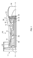
Figure 2 is an enlarged cross-sectional view through a portion of a turbine rotor assembly according to the present invention. -
Figure 3 is a perspective view of a chocking device of a turbine rotor assembly according to the present invention. -
Figure 4 is a perspective view of an alternative chocking device of a turbine rotor assembly according to the present invention. -
Figure 5 is an enlarged cross-sectional view through a portion of an alternative turbine rotor assembly according to the present invention. -
Figure 6 is an enlarged cross-sectional view through a portion of a further turbine rotor assembly according to the present invention. - A turbofan
gas turbine engine 10, as shown infigure 1 , comprises in flow series anintake 11, afan 12, an intermediate pressure compressor 13, ahigh pressure compressor 14, acombustor 15, ahigh pressure turbine 16, an intermediate pressure turbine 17, alow pressure turbine 18 and anexhaust 19. Thehigh pressure turbine 16 is arranged to drive thehigh pressure compressor 14 via afirst shaft 26. The intermediate pressure turbine 17 is arranged to drive theintermediate pressure compressor 14 via asecond shaft 28 and thelow pressure turbine 19 is arranged to drive thefan 12 via athird shaft 30. In operation air flows into theintake 11 and is compressed by thefan 12. A first portion of the air flows through, and is compressed by, the intermediate pressure compressor 13 and thehigh pressure compressor 14 and is supplied to thecombustor 15. Fuel is injected into thecombustor 15 and is burnt in the air to produce hot exhaust gases which flow through, and drive, thehigh pressure turbine 16, the intermediate pressure turbine 17 and thelow pressure turbine 18. The hot exhaust gases leaving thelow pressure turbine 18 flow through theexhaust 19 to provide propulsive thrust. A second portion of the air bypasses the main engine to provide propulsive thrust. - The
high pressure turbine 16, as shown infigure 2 , comprises aturbine rotor assembly 32 according to the present invention. Theturbine rotor assembly 32 comprises a turbine rotor, a turbine disc, 34 and a plurality of circumferentially spaced radially outwardly extendingturbine rotor blades 36. The turbine rotor, turbine disc, 34 has ahub 37 and arim 38 and a plurality of circumferentially spacedslots 40 are provided in therim 38 of the turbine rotor,turbine disc 34. Eachturbine rotor blade 36 has aroot 42 and theroot 42 of eachturbine rotor blade 36 is arranged in a corresponding one of theslots 40 in therim 38 of the turbine rotor,turbine disc 34. Theroot 42 of eachturbine rotor blade 36 is firtree shaped, or dovetail shaped, in cross-section and eachslot 40 is correspondingly shaped to receive theroot 42 of the correspondingturbine rotor blade 36. - The
turbine rotor blades 36 are hollow and are provided withinternal cooling passages 44 to allow a flow of coolant there-through to cool theaerofoil 49 of theturbine rotor blades 36. The coolant is supplied along eachslot 40 in therim 38 of the turbine rotor, turbine disc, 34 to an aperture, or to apertures, 46 in a radiallyinner surface 48 of theroot 42 of the correspondingturbine rotor blade 36. Theaperture 46 in the radiallyinner surface 48 of theroot 42 of eachturbine rotor blade 36 supplies coolant to theinternal cooling passages 44 in theturbine rotor blade 36. - Each of the
slots 40 in therim 38 of the turbine rotor, turbine disc, 34 has achocking device 50 and eachchocking device 50 abuts a radiallyinner surface 52 of thecorresponding slot 40 and eachchocking device 50 also abuts a radiallyinner surface 48 of theroot 42 of the correspondingturbine rotor blade 36. Eachchocking device 50 comprises a thermally insulatingmaterial 54 adjacent the radiallyinner surface 52 of thecorresponding slot 40 in the rim of the turbine rotor, turbine disc, 34 and eachchocking device 50 forms aspace 56 between the thermally insulatingmaterial 54 and the radiallyinner surface 48 of theroot 42 of the correspondingturbine rotor blade 36. - Each
chocking device 50, as shown infigure 3 , comprises amember 58 and the thermally insulatingmaterial 54 is arranged on a radiallyinner surface 60 of themember 58 and a plurality ofprojections 62 extending radially outwardly from themember 58. Eachchocking device 50, infigure 3 , comprises asheet member 58, a thermally insulatingmaterial 54 arranged on the radiallyinner surface 60 of thesheet member 58 and a plurality ofprojections 62 extending radially outwardly from thesheet member 58. - Alternatively each
chocking device 50B, as shown infigure 4 , comprises at least onewire member 58B, a thermally insulatingmaterial 54B arranged on the radiallyinner surface 60B of thewire member 58B and a plurality ofprojections 62B extending radially outwardly from thewire member 58B. Thewire member 58B comprises a single bent wire member or comprises a plurality of wires welded together. Thewire member 58 may comprise an open framework. Thewire member 58B is arranged such that there are no stress concentrations or sharp edges. - The thermally insulating
material material material - The thermally insulating material may comprise an aerogel. The thermally insulating material may comprise a silica aerogel. The thermally insulating material may comprise a silica aerogel containing reinforcing fibres. The thermally insulating material may comprise silica aerogel containing non-woven reinforcing fibres. The thermally insulating material may comprise silica aerogel containing reinforcing glass fibres. The thermally insulating material may comprise Pyrogel XT (RTM) or Pyrogel XTF (RTM) and is obtainable from Aspen Aerogels, Inc, 30 Forbes Road, Building B, Northborough, MA 01532, USA. An aerogel is a highly porous solid formed from a gel and in which the liquid is replaced by a gas.
- In operation of the turbofan
gas turbine engine 10, coolant flows along and/or through eachslot 40 in therim 38 of the turbine rotor, turbine disc, 34 to the aperture, or apertures, 46 in the radiallyinner surface 48 of theroot 42 of the correspondingturbine rotor blade 36. In particular the coolant flows through thespace 56 between the thermally insulatingmaterial 54 of each chockingdevice 50 and the radiallyinner surface 48 of theroot 42 of the correspondingturbine rotor blade 36. The provision of thechocking devices 50 in theslots 40 in therim 38 of the turbine rotor, turbine disc, 34 and in particular the thermally insulatingmaterial 54 reduces the heat transfer from the turbine rotor, turbine disc, 34, e.g. the radiallyinner surfaces 52 of theslots 40, to the coolant flow in theslots 34 in therim 38 of the turbine rotor, turbine disc, 34 and thus reduces the thermal response of those regions of the turbine rotor, turbine disc, 34 adjacent theslots 40 with variations in thrust of thegas turbine engine 10. In other words the thermally insulatingmaterial 54 introduces a thermal lag between the temperature of the coolant flow and the local metal temperature in the regions of the turbine rotor, turbine disc, 34 adjacent theslots 40 during thermal transients, e.g. variations in thrust of thegas turbine engine 10. The thermal lag between the temperature of the coolant flow and the local metal temperature in the regions of the turbine rotor, turbine disc, 34 adjacent theslots 40 reduces the difference between the thermal response of the region of the turbine rotor, turbine disc, 34 adjacent theslots 40 and the remainder of the turbine rotor, turbine disc, 34 for example thehub 37 and therefore reduces the thermal stresses in the region of the turbine rotor, turbine disc, 34 adjacent theslots 40 of the turbine rotor, turbine disc, 34. The thermal lag reduces the thermal gradient between theslots 40 in therim 38 of the turbine rotor, turbine disc, 34 and the hub, or bore, 37 of the turbine rotor, turbine disc, 34, which in turn reduces the thermal stresses in the region of the turbine rotor, turbine disc, adjacent theslots 40. It is predicted that during an acceleration of thegas turbine engine 10 the thermal gradient between theslots 40 and the bore of the turbine rotor, turbine disc, 34 will be reduced by 100°C and it is predicted that during a deceleration the thermal gradient will be reduced by about 50°C for temperatures of theturbine disc 34 up to 650°C. - The aerogel is a soft material and prevents fretting between the radially
inner surface 52 of theslots 40. The provision of awire member 58 reduces the weight of the chockingdevice 50 - A further
turbine rotor assembly 132 according to the present invention is shown infigure 5 . Theturbine rotor assembly 132 is substantially the same as that shown infigure 2 , and like parts are denoted by like numerals. Theturbine rotor assembly 132 differs in that each of theslots 40 in therim 38 of the turbine rotor, turbine disc, 34 has aplate member 150 and eachplate member 150 abuts a radiallyinner surface 52 of thecorresponding slot 40 and eachplate member 150 comprises a thermally insulatingmaterial 154 adjacent the radiallyinner surface 52 of thecorresponding slot 40 in the rim of the turbine rotor, turbine disc, 34 and eachplate member 150 forms aspace 56 between the thermally insulatingmaterial 154 and the radiallyinner surface 48 of theroot 42 of the correspondingturbine rotor blade 36. The thermally insulatingmaterial 154 is arranged on a radiallyinner surface 160 of the plate member 158. Eachplate member 150 may comprise a sheet member. - An axially
upstream end 162 of eachplate member 150 locates in aslot 166 in arim cover plate 168 and an axiallydownstream end 164 of eachplate member 150 locates in aslot 170 in adownstream seal plate 172. Thus therim cover plate 168 and thedownstream seal plate 172 support eachplate member 150. An upstream seal plate 174 is provided radially outwardly of therim cover plate 168. Therim cover plate 168 and the upstream seal plate 174 are located at the upstream end of theturbine rotor 34 and thedownstream seal plate 172 is located at the downstream end of theturbine rotor 34. Therim cover plate 168, the upstream seal plate 174 and thedownstream seal plate 172 prevent the leakage of fluid across theturbine rotor 34 through the gaps between the shanks of theturbine rotor blades 36 and/or between the gaps between theroots 42 of theturbine rotor blades 36 and theslots 40 in theturbine rotor 34. In this arrangement the coolant is arranged to flow to theslots 40 by flowing through the spaces circumferentially betweenadjacent plate members 150. - In another embodiment, it may be possible to arrange for each plate member to be integral with, or joined to, the rim cover plate or to arrange for each plate member to be integral with, or joined to, the downstream seal plate. Some of the plate members may be integral with, or joined to, the rim cover plate and some of the plate members may be integral with, or joined to, the downstream seal plate.
- The turbine rotor may be turbine disc or a turbine drum.
- Although the present invention has been described with reference to providing each slot with a chocking device or a plate member, the present invention is also applicable if at least one of the slots has a chocking device or a plate member.
-
Figure 6 shows a retainingstructure 250 on the radially inner end of the/eachturbine rotor blade 36 to retain the thermally insulatingmaterial 254. The retainingstructure 250 may comprise a box structure. The box structure is open at its upstream end to receive the coolant flow and is closed at its downstream end. The retainingstructure 250 allows the coolant to flow through thebox structure 250 and into the aperture, or apertures, 46 in the radiallyinner surface 48 of theroot 42 of theturbine rotor blade 36. The retainingstructure 250 is spaced from theinner surface 52 and the side surfaces of theslot 40. The thermally insulatingmaterial 154 is adjacent the radiallyinner surface 52 of thecorresponding slot 40 in the rim of the turbine rotor, turbine disc, 34 and each retainingmember 250 forms aspace 56 between the thermally insulatingmaterial 254 and the radiallyinner surface 48 of theroot 42 of the correspondingturbine rotor blade 36. The thermally insulatingmaterial 254 is arranged on a radially inner surface of the retainingstructure 250. The retainingstructure 250 may be integral with, or secured to, theturbine rotor blade 36. The upstream end of each retaining structure may have a plate member arranged to abut the upstream face of the turbine rotor, turbine disc, 34 adjacent therespective slot 40 to form a dead zone between the radiallyinner surface 52 of theslot 40 in the turbine rotor, turbine disc, 34 and the radially inner surface of the retaining structure so that static air may be used as the thermally insulating material. - Although the present invention has been described with reference to the use of a thermally insulating material comprising an aerogel, it is equally possible for other suitable thermally insulating materials to be used. For example the thermally insulating material may be air. If air is the thermally insulating material, the turbine rotor blades are provided with internal cooling passages to allow a flow of coolant there-through to cool the aerofoil of the turbine rotor blades. However, in this embodiment the coolant is supplied between the rim of the turbine rotor, turbine disc, and the platforms of the turbine rotor blades to an aperture, or to apertures, in a surface of the shank of the corresponding turbine rotor blade. In addition some coolant is supplied along each slot in the rim of the turbine rotor, turbine disc, and the coolant is arranged to produce a thermally insulating material, in a dead zone, between the radially inner surface of each slot in the rim of the turbine rotor, turbine disc, and the radially inner surface of the root of each turbine rotor blade. In this case the thermally insulting material may be static air.
Claims (15)
- A turbine rotor assembly (32) comprising a turbine rotor (34) and a plurality of circumferentially spaced radially outwardly extending turbine rotor blades (36), the turbine rotor (34) having a hub (37), a rim (38) and a plurality of circumferentially spaced slots (40) provided in the rim (38) of the turbine rotor (34), each turbine rotor blade (36) having a root (42), the root (42) of each turbine rotor blade (36) being arranged in a corresponding one of the slots (40) in the rim (38) of the turbine rotor (34), each turbine rotor blade (36) being hollow, each turbine rotor blade (36) being provided with at least one internal cooling passage (44) for a coolant, each turbine rotor blade (36) having at least one aperture (46) arranged to supply coolant to the at least one internal cooling passage (44) in the turbine blade (36), characterised in that at least one of the slots (40) having a thermally insulating material (54) adjacent the radially inner surface (52) of the slot (40) wherein the thermally insulating material (54) reduces the temperature gradient between a region of the turbine rotor (34) adjacent the at least one slot (40) and the hub (37) of the turbine rotor (34).
- A turbine rotor assembly as claimed in claim 1 wherein at least one of the slots (40) having a chocking device (50), the at least one chocking device (50) abutting a radially inner surface (52) of the slot (40), the chocking device (50) abutting a radially inner surface (48) of the root (42) of the corresponding turbine rotor blade (36), the chocking device (50) comprising a thermally insulating material (54) adjacent the radially inner surface (52) of the slot (40), and the chocking device (50) forming a space (56) between the thermally insulating material (54) and the radially inner surface (48) of the root (42) of the corresponding turbine rotor blade (36).
- A turbine rotor assembly as claimed in claim 2 wherein each of the slots (40) having a chocking device (50), each chocking device (50) abutting a radially inner surface (52) of the slot (40), each chocking device (50) abutting a radially inner surface (48) of the root (42) of the corresponding turbine rotor blade (36), each chocking device (50) comprising a thermally insulating material (54) adjacent the radially inner surface (52) of the slot (40) and each chocking device (50) forming a space (56) between the thermally insulating material (54) and the radially inner surface (48) of the root (42) of the corresponding turbine rotor blade (36).
- A turbine rotor assembly as claimed in claim 2 or claim 3 wherein each chocking device (50) comprising a member (58), a thermally insulating material (54) being arranged on a radially inner surface (60) of the member (58) and a plurality of projections (62) extending radially outwardly from the member (58).
- A turbine rotor assembly as claimed in claim 4 wherein each chocking device (50) comprising a sheet member (58), a thermally insulating material (54) being arranged on a radially inner surface (60) of the sheet member (58) and a plurality of projections (62) extending radially outwardly from the sheet member (58) or each chocking device (50B) comprising at least one wire member (58B), a thermally insulating material (54B) being arranged on a radially inner surface (60B) of the wire member (58B) and a plurality of projections (62B) extending radially outwardly from the wire member (58B).
- A turbine rotor assembly as claimed in claim 1 wherein at least one of the slots (40) having a plate member (150), the at least one plate member (150) abutting a radially inner surface (52) of the slot (40), the plate member (150) having a thermally insulating material (154) adjacent the radially inner surface (52) of the slot (40), and the plate member (150) forming a space (56) between the thermally insulating material (154) and the radially inner surface (48) of the root (42) of the corresponding turbine rotor blade (36).
- A turbine rotor assembly as claimed in claim 6 wherein each of the slots (40) having a plate member (150), each plate member (150) abutting a radially inner surface (52) of the slot (40), each plate member (150) comprising a thermally insulating material (154) adjacent the radially inner surface (52) of the slot (40) and each plate member (150) forming a space (56) between the thermally insulating material (154) and the radially inner surface (48) of the root (42) of the corresponding turbine rotor blade (36).
- A turbine rotor assembly as claimed in claim 6 or claim 7 wherein the turbine rotor assembly (32) comprises a rim cover plate (156) at a first axial end of the turbine rotor (34) and a seal plate (172) at a second axial end of the turbine rotor (34), each plate member (150) being supported by the rim cover plate (168) and/or the seal plate (172).
- A turbine rotor assembly as claimed in claim 1 wherein a retaining structure (250) on the radially inner end of at least one of the turbine rotor blades (36) retains the thermally insulating material (254).
- A turbine rotor assembly as claimed in any of claims 1 to 9 wherein the thermally insulating material comprises an aerogel, a silica aerogel, a silica aerogel containing reinforcing fibres, a silica aerogel containing non-woven reinforcing fibres or a silica aerogel containing reinforcing glass fibres.
- A turbine rotor assembly as claimed in any of claims 1 to 10 wherein each turbine rotor blade (36) has at least one aperture (46) in a radially inner surface (48) of the root (42).
- A turbine rotor assembly as claimed in claim 1 wherein each turbine rotor blade has at least one aperture in a surface of a shank.
- A turbine rotor assembly as claimed in claim 9 or claim 12 wherein the thermally insulating material comprises air.
- A turbine rotor assembly as claimed in any of claims 1 to 13 wherein the turbine rotor (34) is a turbine disc.
- A turbine rotor assembly as claimed in any of claims 1 to 14 wherein the turbine rotor assembly (32) is a gas turbine engine turbine rotor assembly.
Applications Claiming Priority (1)
| Application Number | Priority Date | Filing Date | Title |
|---|---|---|---|
| GBGB1010929.6A GB201010929D0 (en) | 2010-06-30 | 2010-06-30 | A turbine rotor assembly |
Publications (3)
| Publication Number | Publication Date |
|---|---|
| EP2402557A2 true EP2402557A2 (en) | 2012-01-04 |
| EP2402557A3 EP2402557A3 (en) | 2012-06-27 |
| EP2402557B1 EP2402557B1 (en) | 2018-01-17 |
Family
ID=42583154
Family Applications (1)
| Application Number | Title | Priority Date | Filing Date |
|---|---|---|---|
| EP11168586.3A Not-in-force EP2402557B1 (en) | 2010-06-30 | 2011-06-02 | Turbine rotor assembly |
Country Status (3)
| Country | Link |
|---|---|
| US (1) | US8845288B2 (en) |
| EP (1) | EP2402557B1 (en) |
| GB (1) | GB201010929D0 (en) |
Cited By (2)
| Publication number | Priority date | Publication date | Assignee | Title |
|---|---|---|---|---|
| WO2014052320A1 (en) * | 2012-09-28 | 2014-04-03 | United Technologies Corporation | Uber-cooled multi-alloy integrally bladed rotor |
| DE102014213911A1 (en) * | 2014-07-17 | 2016-01-21 | MTU Aero Engines AG | Airgel lining element for turbomachinery |
Families Citing this family (12)
| Publication number | Priority date | Publication date | Assignee | Title |
|---|---|---|---|---|
| IT1403416B1 (en) * | 2010-12-21 | 2013-10-17 | Avio Spa | BORED ROTOR OF A GAS TURBINE FOR AERONAUTICAL ENGINES AND METHOD FOR COOLING OF THE BORED ROTOR |
| US9869183B2 (en) * | 2014-08-01 | 2018-01-16 | United Technologies Corporation | Thermal barrier coating inside cooling channels |
| US10107102B2 (en) * | 2014-09-29 | 2018-10-23 | United Technologies Corporation | Rotor disk assembly for a gas turbine engine |
| US10280768B2 (en) | 2014-11-12 | 2019-05-07 | Rolls-Royce North American Technologies Inc. | Turbine blisk including ceramic matrix composite blades and methods of manufacture |
| US9909430B2 (en) | 2014-11-13 | 2018-03-06 | Rolls-Royce North American Technologies Inc. | Turbine disk assembly including seperable platforms for blade attachment |
| US20160146016A1 (en) * | 2014-11-24 | 2016-05-26 | General Electric Company | Rotor rim impingement cooling |
| ES2698504T3 (en) * | 2015-07-28 | 2019-02-05 | MTU Aero Engines AG | Gas turbine |
| US10294954B2 (en) | 2016-11-09 | 2019-05-21 | Rolls-Royce North American Technologies Inc. | Composite blisk |
| DE102016124806A1 (en) * | 2016-12-19 | 2018-06-21 | Rolls-Royce Deutschland Ltd & Co Kg | A turbine blade assembly for a gas turbine and method of providing sealing air in a turbine blade assembly |
| US10563665B2 (en) | 2017-01-30 | 2020-02-18 | Rolls-Royce North American Technologies, Inc. | Turbomachine stage and method of making same |
| WO2024079703A1 (en) * | 2022-10-13 | 2024-04-18 | Anglo American Technical & Sustainability Services Ltd | Low carbon fuels |
| US12410720B2 (en) * | 2023-11-02 | 2025-09-09 | General Electric Company | Turbine engine having a rotatable disk and a blade |
Family Cites Families (16)
| Publication number | Priority date | Publication date | Assignee | Title |
|---|---|---|---|---|
| US2874932A (en) | 1952-02-25 | 1959-02-24 | Maschf Augsburg Nuernberg Ag | Steel turbine rotors with ceramic blades |
| DE2108176A1 (en) | 1971-02-20 | 1972-08-31 | Motoren Turbinen Union | Fastening of ceramic turbine blades |
| GB1556274A (en) | 1977-04-19 | 1979-11-21 | Rolls Royce | Blade carrying disc for a gas turbine engine |
| GB2049068B (en) | 1979-05-15 | 1983-02-23 | Rolls Royce | Turbine bladed rotors |
| US4505640A (en) * | 1983-12-13 | 1985-03-19 | United Technologies Corporation | Seal means for a blade attachment slot of a rotor assembly |
| US4659285A (en) | 1984-07-23 | 1987-04-21 | United Technologies Corporation | Turbine cover-seal assembly |
| JPS63173801A (en) | 1987-01-12 | 1988-07-18 | Toshiba Corp | Gas turbine |
| JPS63306206A (en) | 1987-06-05 | 1988-12-14 | Toshiba Corp | Turbine moving blade installation structure |
| JP2785291B2 (en) | 1988-12-23 | 1998-08-13 | 石川島播磨重工業株式会社 | Gas turbine blades |
| JP2869984B2 (en) | 1988-12-23 | 1999-03-10 | 石川島播磨重工業株式会社 | Ceramic wing fitting structure |
| GB2265671A (en) | 1992-03-24 | 1993-10-06 | Rolls Royce Plc | Bladed rotor for a gas turbine engine |
| US5339619A (en) * | 1992-08-31 | 1994-08-23 | United Technologies Corporation | Active cooling of turbine rotor assembly |
| US5735671A (en) | 1996-11-29 | 1998-04-07 | General Electric Company | Shielded turbine rotor |
| JP2002201908A (en) | 2000-12-28 | 2002-07-19 | Ishikawajima Harima Heavy Ind Co Ltd | Turbine blade holding structure |
| GB2412699A (en) | 2004-03-30 | 2005-10-05 | Rolls Royce Plc | Heat shield for rotor blade hub |
| US7887937B2 (en) * | 2007-01-23 | 2011-02-15 | The Boeing Company | Thermal insulation assemblies and methods for fabricating the same |
-
2010
- 2010-06-30 GB GBGB1010929.6A patent/GB201010929D0/en not_active Ceased
-
2011
- 2011-06-02 US US13/151,770 patent/US8845288B2/en not_active Expired - Fee Related
- 2011-06-02 EP EP11168586.3A patent/EP2402557B1/en not_active Not-in-force
Non-Patent Citations (1)
| Title |
|---|
| None |
Cited By (2)
| Publication number | Priority date | Publication date | Assignee | Title |
|---|---|---|---|---|
| WO2014052320A1 (en) * | 2012-09-28 | 2014-04-03 | United Technologies Corporation | Uber-cooled multi-alloy integrally bladed rotor |
| DE102014213911A1 (en) * | 2014-07-17 | 2016-01-21 | MTU Aero Engines AG | Airgel lining element for turbomachinery |
Also Published As
| Publication number | Publication date |
|---|---|
| US20120003103A1 (en) | 2012-01-05 |
| EP2402557B1 (en) | 2018-01-17 |
| GB201010929D0 (en) | 2010-08-11 |
| EP2402557A3 (en) | 2012-06-27 |
| US8845288B2 (en) | 2014-09-30 |
Similar Documents
| Publication | Publication Date | Title |
|---|---|---|
| EP2402557B1 (en) | Turbine rotor assembly | |
| EP3044425B1 (en) | Blade outer air seal having angled retention hook | |
| US10323534B2 (en) | Blade outer air seal with cooling features | |
| US8753073B2 (en) | Turbine shroud sealing apparatus | |
| US9115596B2 (en) | Blade outer air seal having anti-rotation feature | |
| EP2055898B1 (en) | Gas turbine engine with circumferential array of airfoils with platform cooling | |
| US7597533B1 (en) | BOAS with multi-metering diffusion cooling | |
| US10392950B2 (en) | Turbine band anti-chording flanges | |
| EP3594452B1 (en) | Seal segment for a gas turbine engine | |
| EP3121382B1 (en) | Gas turbine engines including channel-cooled hooks for retaining a part relative to an engine casing structure | |
| EP2336497A2 (en) | Blade outer air seal formed of stacked panels | |
| CN106907182B (en) | Turbine airfoil with trailing edge cooling circuit | |
| US7600966B2 (en) | Turbine airfoil with improved cooling | |
| EP3214274B1 (en) | Encapsulated cooling for turbine shrouds | |
| EP1944468B1 (en) | A turbine blade | |
| CN101929357A (en) | Systems, methods, and apparatus for thermally isolating turbine rotor wheels | |
| US10519779B2 (en) | Radial CMC wall thickness variation for stress response | |
| US10280793B2 (en) | Insert and standoff design for a gas turbine engine vane | |
| US9115600B2 (en) | Insulated wall section | |
| EP3192972B1 (en) | Flow exchange baffle insert for a gas turbine engine component | |
| US20190376392A1 (en) | Gas turbine |
Legal Events
| Date | Code | Title | Description |
|---|---|---|---|
| AK | Designated contracting states |
Kind code of ref document: A2 Designated state(s): AL AT BE BG CH CY CZ DE DK EE ES FI FR GB GR HR HU IE IS IT LI LT LU LV MC MK MT NL NO PL PT RO RS SE SI SK SM TR |
|
| AX | Request for extension of the european patent |
Extension state: BA ME |
|
| PUAI | Public reference made under article 153(3) epc to a published international application that has entered the european phase |
Free format text: ORIGINAL CODE: 0009012 |
|
| PUAL | Search report despatched |
Free format text: ORIGINAL CODE: 0009013 |
|
| AK | Designated contracting states |
Kind code of ref document: A3 Designated state(s): AL AT BE BG CH CY CZ DE DK EE ES FI FR GB GR HR HU IE IS IT LI LT LU LV MC MK MT NL NO PL PT RO RS SE SI SK SM TR |
|
| AX | Request for extension of the european patent |
Extension state: BA ME |
|
| RIC1 | Information provided on ipc code assigned before grant |
Ipc: F01D 5/30 20060101ALI20120518BHEP Ipc: F01D 5/08 20060101AFI20120518BHEP |
|
| 17P | Request for examination filed |
Effective date: 20121115 |
|
| RAP1 | Party data changed (applicant data changed or rights of an application transferred) |
Owner name: ROLLS-ROYCE PLC |
|
| STAA | Information on the status of an ep patent application or granted ep patent |
Free format text: STATUS: EXAMINATION IS IN PROGRESS |
|
| 17Q | First examination report despatched |
Effective date: 20170831 |
|
| GRAP | Despatch of communication of intention to grant a patent |
Free format text: ORIGINAL CODE: EPIDOSNIGR1 |
|
| STAA | Information on the status of an ep patent application or granted ep patent |
Free format text: STATUS: GRANT OF PATENT IS INTENDED |
|
| GRAS | Grant fee paid |
Free format text: ORIGINAL CODE: EPIDOSNIGR3 |
|
| INTG | Intention to grant announced |
Effective date: 20171115 |
|
| GRAA | (expected) grant |
Free format text: ORIGINAL CODE: 0009210 |
|
| STAA | Information on the status of an ep patent application or granted ep patent |
Free format text: STATUS: THE PATENT HAS BEEN GRANTED |
|
| AK | Designated contracting states |
Kind code of ref document: B1 Designated state(s): AL AT BE BG CH CY CZ DE DK EE ES FI FR GB GR HR HU IE IS IT LI LT LU LV MC MK MT NL NO PL PT RO RS SE SI SK SM TR |
|
| REG | Reference to a national code |
Ref country code: GB Ref legal event code: FG4D |
|
| REG | Reference to a national code |
Ref country code: CH Ref legal event code: EP |
|
| REG | Reference to a national code |
Ref country code: IE Ref legal event code: FG4D |
|
| REG | Reference to a national code |
Ref country code: AT Ref legal event code: REF Ref document number: 964569 Country of ref document: AT Kind code of ref document: T Effective date: 20180215 |
|
| REG | Reference to a national code |
Ref country code: DE Ref legal event code: R096 Ref document number: 602011045095 Country of ref document: DE |
|
| REG | Reference to a national code |
Ref country code: NL Ref legal event code: MP Effective date: 20180117 |
|
| REG | Reference to a national code |
Ref country code: LT Ref legal event code: MG4D |
|
| REG | Reference to a national code |
Ref country code: AT Ref legal event code: MK05 Ref document number: 964569 Country of ref document: AT Kind code of ref document: T Effective date: 20180117 |
|
| REG | Reference to a national code |
Ref country code: FR Ref legal event code: PLFP Year of fee payment: 8 |
|
| PG25 | Lapsed in a contracting state [announced via postgrant information from national office to epo] |
Ref country code: NL Free format text: LAPSE BECAUSE OF FAILURE TO SUBMIT A TRANSLATION OF THE DESCRIPTION OR TO PAY THE FEE WITHIN THE PRESCRIBED TIME-LIMIT Effective date: 20180117 |
|
| PG25 | Lapsed in a contracting state [announced via postgrant information from national office to epo] |
Ref country code: CY Free format text: LAPSE BECAUSE OF FAILURE TO SUBMIT A TRANSLATION OF THE DESCRIPTION OR TO PAY THE FEE WITHIN THE PRESCRIBED TIME-LIMIT Effective date: 20180117 Ref country code: LT Free format text: LAPSE BECAUSE OF FAILURE TO SUBMIT A TRANSLATION OF THE DESCRIPTION OR TO PAY THE FEE WITHIN THE PRESCRIBED TIME-LIMIT Effective date: 20180117 Ref country code: HR Free format text: LAPSE BECAUSE OF FAILURE TO SUBMIT A TRANSLATION OF THE DESCRIPTION OR TO PAY THE FEE WITHIN THE PRESCRIBED TIME-LIMIT Effective date: 20180117 Ref country code: FI Free format text: LAPSE BECAUSE OF FAILURE TO SUBMIT A TRANSLATION OF THE DESCRIPTION OR TO PAY THE FEE WITHIN THE PRESCRIBED TIME-LIMIT Effective date: 20180117 Ref country code: NO Free format text: LAPSE BECAUSE OF FAILURE TO SUBMIT A TRANSLATION OF THE DESCRIPTION OR TO PAY THE FEE WITHIN THE PRESCRIBED TIME-LIMIT Effective date: 20180417 Ref country code: ES Free format text: LAPSE BECAUSE OF FAILURE TO SUBMIT A TRANSLATION OF THE DESCRIPTION OR TO PAY THE FEE WITHIN THE PRESCRIBED TIME-LIMIT Effective date: 20180117 |
|
| PG25 | Lapsed in a contracting state [announced via postgrant information from national office to epo] |
Ref country code: RS Free format text: LAPSE BECAUSE OF FAILURE TO SUBMIT A TRANSLATION OF THE DESCRIPTION OR TO PAY THE FEE WITHIN THE PRESCRIBED TIME-LIMIT Effective date: 20180117 Ref country code: AT Free format text: LAPSE BECAUSE OF FAILURE TO SUBMIT A TRANSLATION OF THE DESCRIPTION OR TO PAY THE FEE WITHIN THE PRESCRIBED TIME-LIMIT Effective date: 20180117 Ref country code: PL Free format text: LAPSE BECAUSE OF FAILURE TO SUBMIT A TRANSLATION OF THE DESCRIPTION OR TO PAY THE FEE WITHIN THE PRESCRIBED TIME-LIMIT Effective date: 20180117 Ref country code: GR Free format text: LAPSE BECAUSE OF FAILURE TO SUBMIT A TRANSLATION OF THE DESCRIPTION OR TO PAY THE FEE WITHIN THE PRESCRIBED TIME-LIMIT Effective date: 20180418 Ref country code: LV Free format text: LAPSE BECAUSE OF FAILURE TO SUBMIT A TRANSLATION OF THE DESCRIPTION OR TO PAY THE FEE WITHIN THE PRESCRIBED TIME-LIMIT Effective date: 20180117 Ref country code: IS Free format text: LAPSE BECAUSE OF FAILURE TO SUBMIT A TRANSLATION OF THE DESCRIPTION OR TO PAY THE FEE WITHIN THE PRESCRIBED TIME-LIMIT Effective date: 20180517 Ref country code: SE Free format text: LAPSE BECAUSE OF FAILURE TO SUBMIT A TRANSLATION OF THE DESCRIPTION OR TO PAY THE FEE WITHIN THE PRESCRIBED TIME-LIMIT Effective date: 20180117 Ref country code: BG Free format text: LAPSE BECAUSE OF FAILURE TO SUBMIT A TRANSLATION OF THE DESCRIPTION OR TO PAY THE FEE WITHIN THE PRESCRIBED TIME-LIMIT Effective date: 20180417 |
|
| REG | Reference to a national code |
Ref country code: DE Ref legal event code: R097 Ref document number: 602011045095 Country of ref document: DE |
|
| PG25 | Lapsed in a contracting state [announced via postgrant information from national office to epo] |
Ref country code: AL Free format text: LAPSE BECAUSE OF FAILURE TO SUBMIT A TRANSLATION OF THE DESCRIPTION OR TO PAY THE FEE WITHIN THE PRESCRIBED TIME-LIMIT Effective date: 20180117 Ref country code: EE Free format text: LAPSE BECAUSE OF FAILURE TO SUBMIT A TRANSLATION OF THE DESCRIPTION OR TO PAY THE FEE WITHIN THE PRESCRIBED TIME-LIMIT Effective date: 20180117 Ref country code: IT Free format text: LAPSE BECAUSE OF FAILURE TO SUBMIT A TRANSLATION OF THE DESCRIPTION OR TO PAY THE FEE WITHIN THE PRESCRIBED TIME-LIMIT Effective date: 20180117 Ref country code: RO Free format text: LAPSE BECAUSE OF FAILURE TO SUBMIT A TRANSLATION OF THE DESCRIPTION OR TO PAY THE FEE WITHIN THE PRESCRIBED TIME-LIMIT Effective date: 20180117 |
|
| PLBE | No opposition filed within time limit |
Free format text: ORIGINAL CODE: 0009261 |
|
| STAA | Information on the status of an ep patent application or granted ep patent |
Free format text: STATUS: NO OPPOSITION FILED WITHIN TIME LIMIT |
|
| PG25 | Lapsed in a contracting state [announced via postgrant information from national office to epo] |
Ref country code: SK Free format text: LAPSE BECAUSE OF FAILURE TO SUBMIT A TRANSLATION OF THE DESCRIPTION OR TO PAY THE FEE WITHIN THE PRESCRIBED TIME-LIMIT Effective date: 20180117 Ref country code: CZ Free format text: LAPSE BECAUSE OF FAILURE TO SUBMIT A TRANSLATION OF THE DESCRIPTION OR TO PAY THE FEE WITHIN THE PRESCRIBED TIME-LIMIT Effective date: 20180117 Ref country code: DK Free format text: LAPSE BECAUSE OF FAILURE TO SUBMIT A TRANSLATION OF THE DESCRIPTION OR TO PAY THE FEE WITHIN THE PRESCRIBED TIME-LIMIT Effective date: 20180117 Ref country code: SM Free format text: LAPSE BECAUSE OF FAILURE TO SUBMIT A TRANSLATION OF THE DESCRIPTION OR TO PAY THE FEE WITHIN THE PRESCRIBED TIME-LIMIT Effective date: 20180117 |
|
| 26N | No opposition filed |
Effective date: 20181018 |
|
| REG | Reference to a national code |
Ref country code: CH Ref legal event code: PL |
|
| PG25 | Lapsed in a contracting state [announced via postgrant information from national office to epo] |
Ref country code: SI Free format text: LAPSE BECAUSE OF FAILURE TO SUBMIT A TRANSLATION OF THE DESCRIPTION OR TO PAY THE FEE WITHIN THE PRESCRIBED TIME-LIMIT Effective date: 20180117 |
|
| REG | Reference to a national code |
Ref country code: BE Ref legal event code: MM Effective date: 20180630 |
|
| REG | Reference to a national code |
Ref country code: IE Ref legal event code: MM4A |
|
| PG25 | Lapsed in a contracting state [announced via postgrant information from national office to epo] |
Ref country code: MC Free format text: LAPSE BECAUSE OF FAILURE TO SUBMIT A TRANSLATION OF THE DESCRIPTION OR TO PAY THE FEE WITHIN THE PRESCRIBED TIME-LIMIT Effective date: 20180117 Ref country code: LU Free format text: LAPSE BECAUSE OF NON-PAYMENT OF DUE FEES Effective date: 20180602 |
|
| PG25 | Lapsed in a contracting state [announced via postgrant information from national office to epo] |
Ref country code: LI Free format text: LAPSE BECAUSE OF NON-PAYMENT OF DUE FEES Effective date: 20180630 Ref country code: IE Free format text: LAPSE BECAUSE OF NON-PAYMENT OF DUE FEES Effective date: 20180602 Ref country code: CH Free format text: LAPSE BECAUSE OF NON-PAYMENT OF DUE FEES Effective date: 20180630 |
|
| PG25 | Lapsed in a contracting state [announced via postgrant information from national office to epo] |
Ref country code: BE Free format text: LAPSE BECAUSE OF NON-PAYMENT OF DUE FEES Effective date: 20180630 |
|
| PG25 | Lapsed in a contracting state [announced via postgrant information from national office to epo] |
Ref country code: MT Free format text: LAPSE BECAUSE OF NON-PAYMENT OF DUE FEES Effective date: 20180602 |
|
| PG25 | Lapsed in a contracting state [announced via postgrant information from national office to epo] |
Ref country code: TR Free format text: LAPSE BECAUSE OF FAILURE TO SUBMIT A TRANSLATION OF THE DESCRIPTION OR TO PAY THE FEE WITHIN THE PRESCRIBED TIME-LIMIT Effective date: 20180117 |
|
| PG25 | Lapsed in a contracting state [announced via postgrant information from national office to epo] |
Ref country code: HU Free format text: LAPSE BECAUSE OF FAILURE TO SUBMIT A TRANSLATION OF THE DESCRIPTION OR TO PAY THE FEE WITHIN THE PRESCRIBED TIME-LIMIT; INVALID AB INITIO Effective date: 20110602 Ref country code: PT Free format text: LAPSE BECAUSE OF FAILURE TO SUBMIT A TRANSLATION OF THE DESCRIPTION OR TO PAY THE FEE WITHIN THE PRESCRIBED TIME-LIMIT Effective date: 20180117 |
|
| PG25 | Lapsed in a contracting state [announced via postgrant information from national office to epo] |
Ref country code: MK Free format text: LAPSE BECAUSE OF NON-PAYMENT OF DUE FEES Effective date: 20180117 |
|
| PGFP | Annual fee paid to national office [announced via postgrant information from national office to epo] |
Ref country code: FR Payment date: 20210625 Year of fee payment: 11 |
|
| PGFP | Annual fee paid to national office [announced via postgrant information from national office to epo] |
Ref country code: GB Payment date: 20210625 Year of fee payment: 11 |
|
| PGFP | Annual fee paid to national office [announced via postgrant information from national office to epo] |
Ref country code: DE Payment date: 20210827 Year of fee payment: 11 |
|
| REG | Reference to a national code |
Ref country code: DE Ref legal event code: R119 Ref document number: 602011045095 Country of ref document: DE |
|
| GBPC | Gb: european patent ceased through non-payment of renewal fee |
Effective date: 20220602 |
|
| PG25 | Lapsed in a contracting state [announced via postgrant information from national office to epo] |
Ref country code: FR Free format text: LAPSE BECAUSE OF NON-PAYMENT OF DUE FEES Effective date: 20220630 |
|
| PG25 | Lapsed in a contracting state [announced via postgrant information from national office to epo] |
Ref country code: GB Free format text: LAPSE BECAUSE OF NON-PAYMENT OF DUE FEES Effective date: 20220602 Ref country code: DE Free format text: LAPSE BECAUSE OF NON-PAYMENT OF DUE FEES Effective date: 20230103 |