EP2401938A1 - Hair care device - Google Patents
Hair care device Download PDFInfo
- Publication number
- EP2401938A1 EP2401938A1 EP11166912A EP11166912A EP2401938A1 EP 2401938 A1 EP2401938 A1 EP 2401938A1 EP 11166912 A EP11166912 A EP 11166912A EP 11166912 A EP11166912 A EP 11166912A EP 2401938 A1 EP2401938 A1 EP 2401938A1
- Authority
- EP
- European Patent Office
- Prior art keywords
- decorative
- generation unit
- light transmission
- ion generation
- care device
- Prior art date
- Legal status (The legal status is an assumption and is not a legal conclusion. Google has not performed a legal analysis and makes no representation as to the accuracy of the status listed.)
- Withdrawn
Links
- 230000008859 change Effects 0.000 claims abstract description 5
- 150000002500 ions Chemical class 0.000 claims description 56
- 230000005540 biological transmission Effects 0.000 claims description 28
- 239000000463 material Substances 0.000 claims description 12
- 229910003460 diamond Inorganic materials 0.000 abstract description 4
- 239000010432 diamond Substances 0.000 abstract description 4
- 230000004048 modification Effects 0.000 description 15
- 238000012986 modification Methods 0.000 description 15
- 229920003002 synthetic resin Polymers 0.000 description 8
- 239000000057 synthetic resin Substances 0.000 description 8
- 238000005034 decoration Methods 0.000 description 5
- 239000000428 dust Substances 0.000 description 4
- 230000000694 effects Effects 0.000 description 4
- 230000003247 decreasing effect Effects 0.000 description 3
- 239000002184 metal Substances 0.000 description 3
- 230000009467 reduction Effects 0.000 description 3
- 239000000470 constituent Substances 0.000 description 2
- 230000008878 coupling Effects 0.000 description 2
- 238000010168 coupling process Methods 0.000 description 2
- 238000005859 coupling reaction Methods 0.000 description 2
- 230000002349 favourable effect Effects 0.000 description 2
- 238000004519 manufacturing process Methods 0.000 description 2
- 238000000465 moulding Methods 0.000 description 2
- 239000003973 paint Substances 0.000 description 2
- 238000010422 painting Methods 0.000 description 2
- 238000007639 printing Methods 0.000 description 2
- 238000005549 size reduction Methods 0.000 description 2
- 239000013585 weight reducing agent Substances 0.000 description 2
- 230000008901 benefit Effects 0.000 description 1
- 239000003086 colorant Substances 0.000 description 1
- 238000005520 cutting process Methods 0.000 description 1
- 230000006866 deterioration Effects 0.000 description 1
- 238000001035 drying Methods 0.000 description 1
- 238000005516 engineering process Methods 0.000 description 1
- 230000009970 fire resistant effect Effects 0.000 description 1
- 239000011888 foil Substances 0.000 description 1
- 238000005470 impregnation Methods 0.000 description 1
- 230000008018 melting Effects 0.000 description 1
- 238000002844 melting Methods 0.000 description 1
- 230000002093 peripheral effect Effects 0.000 description 1
- 229920000728 polyester Polymers 0.000 description 1
- 229920005989 resin Polymers 0.000 description 1
- 239000011347 resin Substances 0.000 description 1
- 230000004044 response Effects 0.000 description 1
- 238000003466 welding Methods 0.000 description 1
Images









Classifications
-
- A—HUMAN NECESSITIES
- A45—HAND OR TRAVELLING ARTICLES
- A45D—HAIRDRESSING OR SHAVING EQUIPMENT; EQUIPMENT FOR COSMETICS OR COSMETIC TREATMENTS, e.g. FOR MANICURING OR PEDICURING
- A45D20/00—Hair drying devices; Accessories therefor
- A45D20/04—Hot-air producers
- A45D20/08—Hot-air producers heated electrically
- A45D20/10—Hand-held drying devices, e.g. air douches
- A45D20/12—Details thereof or accessories therefor, e.g. nozzles, stands
-
- A—HUMAN NECESSITIES
- A45—HAND OR TRAVELLING ARTICLES
- A45D—HAIRDRESSING OR SHAVING EQUIPMENT; EQUIPMENT FOR COSMETICS OR COSMETIC TREATMENTS, e.g. FOR MANICURING OR PEDICURING
- A45D2200/00—Details not otherwise provided for in A45D
- A45D2200/20—Additional enhancing means
- A45D2200/202—Ionisation
Definitions
- the present invention relates to a hair care device.
- a hair care device as a hair care device, a device has been known, in which a decorative body having patterns such as pictures and illustrations drawn thereon is inserted into an inner surface of a main body case, at least a part of which is made capable of being see-through.
- the present invention is a hair care device including: a housing having, in an inside thereof, a wind tunnel portion provided with an air inlet port and an air blower port; and an air blower unit that discharges, from the air blower port, air sucked from the air inlet port, characterized in that a transparent or translucent light transmission portion is formed in at least a part of the housing, and a decorative portion is provided on a back surface of the light transmission portion, and the decorative portion is formed of an aggregate of plural surfaces.
- a hair dryer is illustrated as a hair care device in this embodiment. Note that, in Fig. 1 , reference symbol Fr denotes a forward direction, and reference symbol Up denotes an upward direction.
- a hair dryer (hair care device) 1 includes: a housing 3 having a wind tunnel portion 2 that exerts a hair care function by hot wind/cold wind; and a grip portion 5 coupled, so as to be freely foldable, to a grip attachment portion 31 protruded from a lower side of a rear end portion of the housing 3 while interposing a coupling portion 3.
- the housing 3 is formed by combining and coupling housing parts, which are divided into right and left halves, to each other.
- an air inlet port 2a is provided, and on a front end portion thereof (that is, a left side in Fig. 1 ), air blower port 2b is provided.
- an air blower unit and a heater are arranged in series from the rear toward the front.
- the wind tunnel portion 2 is set to the housing 3 in a state of ensuring an air flow passage, which is cylindrical, with an inner surface of the housing 3, and these wind tunnel portion 2 and housing 3 are integrated with each other. Then, onto a tip end of the wind tunnel portion 2, a connection 9 for connecting a nozzle 7 is attached.
- the air blower port 2b is located on a tip end of the nozzle 7 attached onto the front end portion of the wind tunnel portion 2; however, in the case where this nozzle 7 is detached, the tip end (tip end of the connection portion 9) of the wind tunnel portion 2 serves as the air blower port 2b.
- the air blower unit 6 is composed of: a fan 61; a motor 62 that rotates this fan 61; and flow adjustment stems 63 63 which support the motor 62 in the inside of the wind tunnel portion 2 and have a low adjustment function for air passing therethrough; and the like. Then, the fan 61 is rotationally driven by the motor 62, whereby an air flow is generated in the wind tunnel portion 2, and the air sucked from the air inlet port 2a is blown out from the air blower port 2b. At this time, when the heater is energized and heated, then the air blown from the air blower port 2b can be turned to the hot wind.
- an ion generation unit 8 that generates and discharges negative ions (ions) is provided.
- This ion generation unit 8 includes an ion generation block 81 that generates the negative ions.
- the ion generation unit 8 introduces a part of the air, which flows in the wind tunnel portion 2, from an opening portion 2K formed by partially cutting away the upper part of the wind tunnel portion 2, and together with the introduced air, discharges the generated negative ions forward from an ion discharge port 83.
- the negative ions discharged from the ion discharge port 83 are blown to hair, whereby the hair can be given a gloss and a moist feeling, and curl of the hair can be taken out.
- the ion generation unit 8 is provided with an ion generation unit cover 85, which holds the ion generation block 81 (refer to Fig. 9 ), and in addition, forms an air introduction passage 84 for introducing the air from the wind tunnel portion 2, and forms the ion discharge port 83.
- This ion generation unit cover 85 is formed of a synthetic resin material.
- a switch SW that is freely switchable among a plurality of up and down stages is provided.
- ON/OFF of the motor 62 and the heater and adjustment of a quantity of the air are performed.
- a cord C to be connected to a power supply is attached to a lower end of the grip portion 5.
- a protection frame main body 10 is attached, which finely divides an opening region of the air inlet port 2a concerned.
- this protection frame main body 10 a relatively large foreign object is prevented from entering the wind tunnel portion 2 by mistake.
- a plurality of annular frame portions 10b arranged concentrically about a substantial center of the air inlet port 2a; and a plurality of linear frame portions 10c extended radially from the substantial center of the air inlet port 2a so as to intersect the respective annular frame portions 10b. Then, openings 10a are defined by these annular frame portions 10b and linear frame portions 10c.
- inside linear portions 10cA located in an inside of an annular frame portion 10bA, which serves as the innermost circumferential-side one among the plurality of annular frame portions 10b, and outside linear portions 10cB located on an outside of the annular frame portion 10bA concerned are shifted from each other with respect to linear directions as diameter directions.
- the inside linear frame portions 10cA and the outside linear portions 10cB are shifted from each other as described above, whereby an edge is not erected on an intersection of the center portion. Accordingly, strength of a metal mold can be ensured, and in addition, a mesh-like filter 11 can also be arranged in the annular frame portion 10bA serving as the innermost circumferential-side one.
- the mesh-like filter 11 is arranged, which divides the openings 10a of the protection frame main body 10 more finely.
- the mesh-like filter 11 has a function to suppress relatively small foreign objects such as dirt, dust and hair from entering the wind tunnel portion 2.
- the mesh-like filter 11 is formed of metal mesh or mesh composed of fire-resistant resin such as polyester, and preferably, the mesh-like filter 11 has a mesh width as fine as 300 to 650 ⁇ m, in which an aperture ratio ranges from 50 to 90 percent (preferably, 50 to 75 percent) .
- the protection frame main body 10 is formed of a synthetic resin material, and preferably, a thickness thereof is approximately 1.5 mm. Moreover, the protection frame main body 10 and the mesh-like filter 11 are molded integrally with each other by a synthetic resin material, and at this time, among such synthetic resin materials for use in the molding, it is preferable to use ABS, which has a low melting point, in terms of preventing a deterioration of the mesh-like filter 11 at the time of the molding.
- the mesh-like filter 11 becomes prone to be peeled off at the time of performing cleanup therefor; however, if the protection frame main body 10 and the mesh-like filter 11 are molded integrally with each other, then the mesh-like filter 11 can be suppressed from being peeled off from the protection frame main body 10.
- the protection frame main body 10 and the mesh-like filter 11 are molded integrally with each other, whereby it becomes possible to prevent the peeling off of the mesh-like filter 11 more surely at the time of performing the cleanup therefor.
- the protection frame main body 10 and the mesh-like filter 11 are molded integrally with each other, whereby a sense of togetherness of both thereof is enhanced, thus making it possible to further enhance the exterior appearance thereof.
- first frames 10c1 which serve as main frames
- second frames 10c2 and third frames 10c3, which serve as sub-frames preferably, a width of the first frames 10c1 is set at approximately 2 mm, and a width of the second frames 10c2 and the third frames 10c3 is set at approximately 1.5 mm.
- the number of first frames 10cl which serve as the main frames and have the largest width, is different from the number of flow adjustment stems 63 and the number of fins of the fan 61 in the air blower unit 6 in consideration of a problem of noise caused by a resonance.
- the number of flow adjustment stems 63 is set at seven
- the number of fins of the fan 61 is set at six
- the number of first frames 10c1 is set at eight.
- the second frames 10c2 are arranged at intermediate points between the first frames 10c1, whereby strength of the protection frame main body 10 can be further increased.
- the third frames 10c3 are made capable of ensuring strength of the mesh-like filter 11 at the time when the protection frame main body 10 is molded integrally with the mesh-like filter 11.
- strength of the air inlet port 2a is enhanced by increasing the arrangement number of bars such as the annular frame portions 10b and the linear frame portions 10c, and a breakage of the air inlet port 2a, which may be caused by droppage and an impact, can be further reduced. Meanwhile, in terms of performance, the quantity of the air is decreased by the increase of the bars. Therefore, in consideration of a balance among these factors, the number of annular frame portions 10b and the number of linear frame portions 10c in the protection frame main body 10 are decided.
- a shape of each of the openings 10a of the protection frame main body 10 is a substantially trapezoidal shape by the annular frame portions 10b and the linear frame portions 10c; however, without being limited to this, it is also possible to form the protection frame main body 10 so that a honeycomb structure in which each of the openings 10a becomes hexagonal can be adopted therefor.
- the honeycomb structure is adopted for the protection frame main body 10 including the openings 10a, then strength of the bar portions can be kept uniform. In addition, a total area of the openings 10a can be further increased. Accordingly, the quantity of the air can be further increased.
- a protection frame sub-body 12 is provided more on an outside of the mesh-like filter 11. Openings 12a of this protection frame main-body 12 corresponds to the openings 10a of the protection frame main body 10, and a shape thereof is substantially the same as the shape of the openings 10a. That is to say, the protection frame sub-body 12 includes annular frame portions 12b and linear frame portions 12c, which are similar to those of the protection frame main body 10. Then, the openings 10a and 12a of these protection frame main body 10 and support frame sub-body 12 are allowed to substantially coincide with an inflow direction of the air.
- the openings 10a of the protection frame main body 10 and the openings 12a of the protection frame sub-body 12 are allowed to coincide with each other, whereby strength thereof can be ensured while suppressing the quantity of the air from being decreased.
- the protection frame sub-body 12 is molded of a synthetic resin material in a similar way to the protection frame main body 10 and the mesh-like filter 11, and these protection frame main body 10, mesh-like filter 11 and protection frame sub-body 12 are molded integrally with one another.
- the protection frame main body 10 and the mesh-like filter 11 are molded integrally with each other, whereby it becomes possible to prevent the peeling off of the mesh-like filter 11 more surely. Moreover, the outside of the mesh-like filter 11 can be covered with the protection frame sub-body 12, and accordingly, the breakage of the mesh-like filter 11 owing to rubbing and the like can be suppressed, and durability of the mesh-like filter 11 can be further enhanced.
- the protection frame sub-body 12 is formed so that a thickness thereof can be thinner than the thickness of the protection frame main body 10.
- the thickness of the protection frame main body 10 is approximately 1.5 mm, it is preferable that the protection frame sub-body 12 be formed at a thickness of approximately 0.2 mm.
- the protection frame sub-body 12 is formed so that the thickness thereof can be thinner than the thickness of the protection frame main body 10, whereby it is facilitated to remove the dust in the case where the dust adheres onto the mesh-like filter 11.
- the protection frame main body 10 is coupled integrally or tightly to the housing 3 so as to be undetachable therefrom.
- the protection frame main body 10 is made undetachable, whereby the mesh-like filter 11 and the protection frame sub-body 12, which are molded integrally therewith, also become undetachable.
- attachment projections 10d are formed on a plurality of spots or entire circumference of a peripheral edge portion of the protection frame main body 10, and the attachment projections 10d are adhered or inserted with pressure to the housing 3 at the time of fitting the attachment projections 10d concerned to an outer circumference of the rear end portion of the housing 3. In such a way, the detachment of the protection frame main body 10 is not performed easily, and the protection frame main body 10 can be made undetachable in a usual operation.
- the protection frame main body 10 is coupled integrally or tightly to the housing 3 so as to be undetachable therefrom.
- the number of parts can be reduced, and a cost reduction, a weight reduction and a size reduction can be thereby achieved.
- the filter member is freely detachably attached to the air inlet port 2a, it is necessary to install still another filter on a depth side in order to prevent the finger and the like from entering the wind tunnel portion 2 in the case of detaching the filter member concerned.
- the filter member adopts a double structure, and accordingly, a cost increase, a weight increase and a size increase, which are caused by an increase of the number of parts, are brought about.
- the protection frame main body 10 is made undetachable as in this embodiment, whereby it becomes unnecessary to install another filter member, and the number of parts can be reduced. Accordingly, the cost reduction, the weight reduction and the size reduction can be achieved.
- the protection frame main body 10 is made undetachable in advance, whereby an apprehension is eliminated that the protection frame main body 10 may be lost.
- a transparent or translucent light transmission portion is formed in at least a part of the housing 3.
- At least a part of the housing 3, that is, a portion, which covers the ion generation unit 8 provided in an upper part of the housing 3 in this embodiment, is composed of a transparent or translucent decorative case 20 in which a decorative portion 21 is provided on a back side (a center direction side of the housing 3).
- This decorative case 20 is integrally molded of a transparent or translucent synthetic resin material.
- the decorative portion 21 formed of an aggregate of plural surfaces is provided.
- the decorative portion 21 provided on the back surface of the decorative case 20 is formed into a diamond cut-like polyhedral shape formed out by a thickness change of the decorative case 20 as shown in Fig. 10 .
- the decorative portion 21 with the polyhedral shape is coated with paint (an opaque material) having metallic gloss . That is to say, the decorative portion 21 contains an opaque material.
- the decorative portion 21 may be subjected to impregnation of metal foil and printing by various colors besides the metallic painting.
- an outer surface of the decorative case 20 may be subjected to the decoration by the printing.
- the decorative case 20 is attached to the housing 3 in such a manner that engagement pieces 23 provided on both sides of a substantial center portion thereof in a fore-and-aft direction are engaged with hook pieces 32 protruded from the inside of the housing 3.
- an engagement piece 24 provided on a rear end portion of the decorative case 20 is engaged with an engagement portion 2c that is located in the inside of the housing 3 and is protruded from the outside of the wind tunnel portion 2.
- hook portions 22 provided on both sides of a front end portion of the decorative case 20 are allowed to sink into insides of the connection portions 9, whereby the decorative case 20 is attached to the housing 3.
- the engagement pieces 23, the hook portions 22 and the engagement pieces 24 are allowed to individually perform the engagement at positions invisible from the outside.
- the ion generation unit cover 85 is arranged in the inside of the decorative case 20; however, this ion generation unit cover 85 is adapted not to be engaged with the decorative case 20. Specifically, as shown in Fig. 4 and Fig. 15 , an engagement portion (a right end portion in Fig. 4 ) 85a of the ion generation unit cover 85 is engaged with an engagement piece 33 of the housing 3, and in addition, as shown in Fig. 13 and Fig. 14 , engagement portions 85b formed on a front end of the ion generation unit cover 85 are allowed to sink into the insides of the connection portions 9 and to engage therewith.
- the engagement portions 85a and 85b of the ion generation unit cover 85 are set to state of being invisible from the outside through the transparent or translucent decorative case 20.
- the ion generation unit cover 85 in a state of being arranged in the inside of the decorative case (light transmission portion) 20, the ion generation unit cover 85 is engaged and held on a region of the housing 3, which is other than the decorative case (light transmission portion) 20, that is, a region in which the light transmission portion is not formed.
- the fan 61 rotates by turning on the switch SW, and the air is introduced into the wind tunnel portion 2. Then, the air introduced from the air inlet port 2a is blown out toward the hair from the air blower port 2b.
- a blown wind can be switched between a hot wind and a cold wind by turning on and off the heater, whereby styling and drying of the hair can be arbitrarily performed.
- the ion generation unit 8 is actuated, whereby the negative ions can be discharged toward the hair from the ion discharge port 83 of the ion generation unit 8. In such a way, the gloss and the moist feeling are given to the hair, and the curl of the hair is taken out effectively, and so on.
- the transparent or translucent light transmission portion is formed in the decorative case (at least a part of the housing 3) 20, and in addition, the decorative portion 21 formed of the polyhedral shape (the aggregate of the plural surfaces) is provided on the back surface of the light transmission portion. Therefore, when the decorative case 20 is viewed from the outside, light is reflected on the polyhedral shape of the decorative portion 21, whereby a shade pattern excellent in design can be generated. In such a way, a profound decorative effect that has not been present heretofore can be produced, an exterior appearance of the hair dryer 1 can be further enhanced, and a commercial value thereof can be thereby further enhanced.
- the decorative portion 21 is provided on the back side of the decorative case 20, whereby the number of parts is reduced, thus making it possible to suppress the cost increase and the weight increase.
- the hair dryer (hair care device) 1 excellent in decorativeness can be obtained while suppressing the cost increase and the weight increase. Furthermore, the number of parts can be reduced, and accordingly, a reduction of production steps can be achieved, and production efficiency can also be suppressed from being decreased.
- the decorative portion 21 is formed into the polyhedral shape by the thickness change of the decorative case 20. Therefore, the shade pattern of the light reflected on the decoration of the back surface of the decorative case 20 is changed in response to the thickness change of the transparent or translucent decorative case 20. In such a way, the hair dryer (hair care device) 1 with more profoundness and excellent design can be obtained.
- the decorative portion 21 contains the opaque material such as the metallic paint. Accordingly, when the transparent or translucent decorative case 20 is viewed from the outside, the engagement portions in the inside thereof can be made invisible by hiding the same by the opaque portion of the decorative portion 21. In such a way, the shade pattern of the light reflected by the decorative portion 21 on the back surface is prevented from being damaged by the engagement portions. Accordingly, the exterior appearance of the hair dryer (hair care device) 1 is made favorable, thus making it possible to further enhance the commercial value thereof.
- the hair dryer (hair care device) 1 includes the ion generation unit 8 that generates and discharges the ions.
- this ion generation unit 8 has the ion generation unit cover 85, and the ion generation unit cover 85 is engaged and held on the region of the housing 3, in which the decorative case (light transmission portion) 20 is not formed, in a state of being arranged in the inside of the decorative case (light transmission portion) 20.
- this ion generation unit cover 85 is held by being engaged with only the housing 3. In such a way, the ion generation unit cover 85 is not engaged with the decorative case 20, and the engagement portions of the ion generation unit cover 85 can be made invisible from the outside of the transparent or translucent decorative case 20. As a result, the exterior appearance of the portion of the decorative case 20 is made favorable, thus making it possible to further enhance the commercial value.
- the decorative case 20 which is replaceable (detachable), is used as the transparent or translucent light transmission portion.
- a plurality of the decorative cases 20 patterned with pictures and illustrations are prepared, and these decorative cases 20 are replaced, whereby the hair dryer (hair care device) 1, which have a variety of variations, can be obtained.
- Fig. 16 and Fig. 17 show a first modification example of the first embodiment.
- the decorative case 20 and the ion generation unit cover 85 which are formed of the synthetic resin material, are molded integrally with each other.
- the decorative portion 21 as a light reflection surface is formed on a boundary surface between the decorative case 20 and the ion generation unit cover 85.
- the decorative case 20 and the ion generation unit cover 85 are molded integrally with each other by the synthetic resin material, and accordingly, the number of parts can be reduced. Furthermore, at the time of assembly, only the decorative case 20 just needs to be engaged with the housing 3 side. Accordingly, enhancement of assembly workability can be achieved, and the hair dryer (hair care device) 1 with lower cost can be obtained.
- Fig. 18 to Fig. 20 show a second modification example of the first embodiment, and show the case where an outside of the decorative case 20 is covered with a transparent or translucent second decorative case (second light transmission portion) 30.
- the second decorative case 30 is formed substantially along an outer shape of the decorative case 20, and is formed a little smaller than the decorative case 20. Then, the second decorative case 30 is joined integrally to the outside of the decorative case 20. This second decorative case 30 is subjected to arbitrary decoration that enables the inside decorative case 20 to be seen through.
- the outside of the decorative case (light transmission portion) 20 is covered with the transparent or translucent second decorative case (second light transmission portion) 30. Accordingly, the decoration of the second decorative case 30 transmits through the decorative case 20, becomes a shade, and is projected on the decorative portion 21 on the back surface thereof. In such a way, in combination with the shade of the light of the decorative case 20, the hair dryer (hair care device) 1, which is excellent in design, can be obtained.
- a brush-added hair dryer 1A is illustrated as the hair care device.
- Fig. 21 and Fig. 22 show only a main body portion 100 of the hair dryer 1A, from which a brush portion is detached, and in Fig. 22 , reference symbol Fr denotes the forward direction, and reference symbol Up denotes the upward direction.
- the hair dryer 1A basically has a similar configuration to that of the hair dryer 1 of the above-mentioned first embodiment; however does not have the grip portion 5, and is used by directly gripping the main body portion 100.
- the main body portion 100 includes the wind tunnel portion 2 having the air blower unit 6. Then, onto the air inlet port 2a provided on the rear end portion of the wind tunnel portion 2, there are attached the protection frame main body 10, the mesh-like filter 11 and the protection frame sub-body 12 as shown in Fig. 23 . Note that these protection frame main body 10, mesh-like filter 11 and protection frame sub-body 12 are formed into shapes matched with the air inlet port 2a according to this embodiment.
- the cord C to be connected to the power supply penetrates the center portions of the protection frame main body 10, the mesh-like filter 11 and the protection frame sub-body 12, and is then connected to the inside of the housing 3.
- a heater device H is provided downstream of the air blower unit 6, and the switch SW that controls ON/OFF, the quantity of the air and a temperature of the hot wind is provided on a side surface of the main body portion 100.
- the air blower port 2b is provided on the front end portion of the wind tunnel portion 2, and this air blower port 2b serves as an attachment hole to which a brush (not shown) is freely detachably fitted.
- the ion generation unit 8 is provided on the upper part of the wind tunnel portion 2 in a similar way to the above-mentioned first embodiment, and the portion that covers this ion generation unit 8 is composed of a decorative case (light transmission portion) 20A.
- a decorative case 21 formed into a diamond cut shape is provided, and the decorative portion 21 is subjected to metallic painting and the like.
- the brush (not shown) is attached to the air blower port 2b, and the switch SW is turned on, whereby the wind such as the cold wind and the hot wind is blown out from the air blower port 2b. Then, the wind thus blown out passes through an inside of the brush, and is blown out from a surface on which bristles of the brush are formed. In such a way, the wind can be blown to the hair while combing the hair by the brush. Furthermore, the negative ions are discharged toward the hair from the ion generation unit 8, whereby the gloss and the moist feeling can be given to the hair, and the curl of the hair can be taken out effectively.
- the light transmission portion is provided in the portion that covers the ion generation unit; however, without being limited to this, the light transmission portion may be provided in a spot other than the ion generation unit, or may be provided entirely in the housing.
- each aggregate of the plural surfaces may be formed, for example, by combining a plurality of curved surfaces with one another or combining curved surfaces and flat surfaces with one another. At this time, boundary portions between the respective surfaces may be made linear or curved.
- the present invention is also applicable to a hair care device in which the ion generation unit is not provided.
- specifications (shapes, sizes, layout and the like) of the housing, the light transmission portion and other details are also appropriately changeable.
Landscapes
- Cleaning And Drying Hair (AREA)
Abstract
A portion that serves as a part of a housing 3 and covers an ion generation unit 8 is composed of a transparent or translucent decorative case 20 in which a decorative portion 21 is provided on a back surface, and the decorative portion 21 is formed into a diamond cut-like polyhedral shape formed out by a thickness change of the decorative case 20.
Description
- This application is based upon and claims the benefit of priority from prior Japanese Patent Application
P2010-149091 filed on June 30, 2010 - The present invention relates to a hair care device.
- Heretofore, as disclosed in Japanese Patent No.
3160654 - However, in the above-described conventional technology, it is necessary to separately form the decorative body on which decorations are put up, and to insert and attach the decorative body into an inside of the main body case, and accordingly, there has been a problem that a cost increase and a weight increase are brought about.
- In this connection, it is an object of the present invention to obtain a hair care device excellent in decorativeness while suppressing the cost increase and the weight increase.
- In order to achieve the foregoing object, the present invention is a hair care device including: a housing having, in an inside thereof, a wind tunnel portion provided with an air inlet port and an air blower port; and an air blower unit that discharges, from the air blower port, air sucked from the air inlet port, characterized in that a transparent or translucent light transmission portion is formed in at least a part of the housing, and a decorative portion is provided on a back surface of the light transmission portion, and the decorative portion is formed of an aggregate of plural surfaces.
-
-
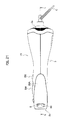
Fig. 1 is a side view of a hair dryer according to a first embodiment of the present invention. -
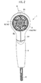
Fig. 2 is a back view of the hair dryer shown inFig. 1 . -
Fig. 3 is a plan view of the hair dryer shown inFig. 1 . -
Fig. 4 is a cross-sectional view along a line A-A inFig. 3 . -
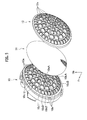
Fig. 5 is a perspective view where a protection frame main body, a mesh-like filter and a protection frame sub-body, which are attached to an air inlet port of the hair dryer shown inFig. 1 , are arrayed. -
Fig. 6 is a cross-sectional view showing a relationship between an ion generation unit cover of an ion generation unit provided in the hair dryer shown inFig. 1 and a decorative case provided thereon. -
Fig. 7 is a cross-sectional view along a line B-B inFig. 3 . -
Fig. 8 is an enlarged cross-sectional view of a portion C inFig. 7 . -
Fig. 9 is a cross-sectional view along a line D-D inFig. 4 . -
Fig. 10 is a cross-sectional view along a line E-E inFig. 4 . -
Fig. 11 is a cross-sectional view along a line F-F inFig. 3 . -
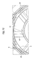
Fig. 12 is an enlarged cross-sectional view of a portion G inFig. 11 . -
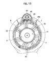
Fig. 13 is a cross-sectional view along a line H-H inFig. 3 . -
Fig. 14 is an enlarged cross-sectional view of a portion I inFig. 13 . -
Fig. 15 is an enlarged cross-sectional view of a portion J inFig. 4 . -
Fig. 16 is a bottom view of a decorative case, which shows a first modification example of the first embodiment of the present invention, when viewed from an inside thereof. -
Fig. 17 is a cross-sectional view along a line K-K inFig. 16 . -
Fig. 18 is a side view of a decorative case showing a second modification example of the first embodiment of the present invention. -
Fig. 19 is a back view of the decorative case shown inFig. 18 when viewed from rear. -
Fig. 20 is a front view of the decorative case shown inFig. 18 when viewed from front. -
Fig. 21 is a plan view showing a main body portion of a brush-added hair dryer according to a second embodiment of the present invention. -
Fig. 22 is a cross-sectional view along a line L-L inFig. 21 . -
Fig. 23 is a side view where a protection frame main body, a mesh-like filter and a protection frame sub-body, which are attached to an air inlet port of the hair dryer shown inFig. 21 , are arrayed. - A description is made below in detail of embodiments of the present invention while referring to the drawings. Note that similar constituents are included in a plurality of the following embodiments. Hence, in the following, common reference numerals are assigned to those similar constituents, and a duplicate description is omitted.
- A hair dryer is illustrated as a hair care device in this embodiment. Note that, in
Fig. 1 , reference symbol Fr denotes a forward direction, and reference symbol Up denotes an upward direction. - As shown in
Fig . 1 to Fig. 4 , a hair dryer (hair care device) 1 according to this embodiment includes: ahousing 3 having awind tunnel portion 2 that exerts a hair care function by hot wind/cold wind; and agrip portion 5 coupled, so as to be freely foldable, to agrip attachment portion 31 protruded from a lower side of a rear end portion of thehousing 3 while interposing acoupling portion 3. Note that thehousing 3 is formed by combining and coupling housing parts, which are divided into right and left halves, to each other. - In the
wind tunnel portion 2, on a rear end portion thereof (that is, a right side inFig. 1 ), anair inlet port 2a is provided, and on a front end portion thereof (that is, a left side inFig. 1 ),air blower port 2b is provided. In an inside of thewind tunnel portion 2, an air blower unit and a heater (not shown) are arranged in series from the rear toward the front. Moreover, thewind tunnel portion 2 is set to thehousing 3 in a state of ensuring an air flow passage, which is cylindrical, with an inner surface of thehousing 3, and thesewind tunnel portion 2 andhousing 3 are integrated with each other. Then, onto a tip end of thewind tunnel portion 2, aconnection 9 for connecting anozzle 7 is attached. Note that, in this embodiment, theair blower port 2b is located on a tip end of thenozzle 7 attached onto the front end portion of thewind tunnel portion 2; however, in the case where thisnozzle 7 is detached, the tip end (tip end of the connection portion 9) of thewind tunnel portion 2 serves as theair blower port 2b. - The
air blower unit 6 is composed of: afan 61; amotor 62 that rotates thisfan 61; and flow adjustment stems 63 63 which support themotor 62 in the inside of thewind tunnel portion 2 and have a low adjustment function for air passing therethrough; and the like. Then, thefan 61 is rotationally driven by themotor 62, whereby an air flow is generated in thewind tunnel portion 2, and the air sucked from theair inlet port 2a is blown out from theair blower port 2b. At this time, when the heater is energized and heated, then the air blown from theair blower port 2b can be turned to the hot wind. - Moreover, on an upper part of the
wind tunnel portion 2, anion generation unit 8 that generates and discharges negative ions (ions) is provided. Thision generation unit 8 includes anion generation block 81 that generates the negative ions. A high voltage, which is generated in a highvoltage generation unit 82 arranged in thegrip attachment portion 31, is applied to theion generation unit 8, and a corona discharge is caused, whereby the negative ions are generated. - The
ion generation unit 8 introduces a part of the air, which flows in thewind tunnel portion 2, from anopening portion 2K formed by partially cutting away the upper part of thewind tunnel portion 2, and together with the introduced air, discharges the generated negative ions forward from anion discharge port 83. As described above, the negative ions discharged from theion discharge port 83 are blown to hair, whereby the hair can be given a gloss and a moist feeling, and curl of the hair can be taken out. - In this embodiment, the
ion generation unit 8 is provided with an iongeneration unit cover 85, which holds the ion generation block 81 (refer toFig. 9 ), and in addition, forms anair introduction passage 84 for introducing the air from thewind tunnel portion 2, and forms theion discharge port 83. This iongeneration unit cover 85 is formed of a synthetic resin material. - On a front center portion of the
grip portion 5, a switch SW that is freely switchable among a plurality of up and down stages is provided. By this switch SW, ON/OFF of themotor 62 and the heater and adjustment of a quantity of the air are performed. Moreover, a cord C to be connected to a power supply is attached to a lower end of thegrip portion 5. - As shown in
Fig. 4 andFig. 5 , to theair inlet port 2a, a protection framemain body 10 is attached, which finely divides an opening region of theair inlet port 2a concerned. By this protection framemain body 10, a relatively large foreign object is prevented from entering thewind tunnel portion 2 by mistake. - In the protection frame
main body 10, as shown inFig. 5 , there are provided: a plurality ofannular frame portions 10b arranged concentrically about a substantial center of theair inlet port 2a; and a plurality oflinear frame portions 10c extended radially from the substantial center of theair inlet port 2a so as to intersect the respectiveannular frame portions 10b. Then,openings 10a are defined by theseannular frame portions 10b andlinear frame portions 10c. - At this time, with regard to the
linear frame portions 10c, inside linear portions 10cA located in an inside of an annular frame portion 10bA, which serves as the innermost circumferential-side one among the plurality ofannular frame portions 10b, and outside linear portions 10cB located on an outside of the annular frame portion 10bA concerned are shifted from each other with respect to linear directions as diameter directions. - The inside linear frame portions 10cA and the outside linear portions 10cB are shifted from each other as described above, whereby an edge is not erected on an intersection of the center portion. Accordingly, strength of a metal mold can be ensured, and in addition, a mesh-
like filter 11 can also be arranged in the annular frame portion 10bA serving as the innermost circumferential-side one. - More on an outside of the protection frame
main body 10, as shown inFig. 5 , the mesh-like filter 11 is arranged, which divides theopenings 10a of the protection framemain body 10 more finely. The mesh-like filter 11 has a function to suppress relatively small foreign objects such as dirt, dust and hair from entering thewind tunnel portion 2. - In this case, the mesh-
like filter 11 is formed of metal mesh or mesh composed of fire-resistant resin such as polyester, and preferably, the mesh-like filter 11 has a mesh width as fine as 300 to 650 µm, in which an aperture ratio ranges from 50 to 90 percent (preferably, 50 to 75 percent) . By using the mesh-like filter 11 with the fine mesh width as described above, small dust, hair and the like can be more effectively prevented from entering thefan 61, themotor 62 and the heater portion. - The protection frame
main body 10 is formed of a synthetic resin material, and preferably, a thickness thereof is approximately 1.5 mm. Moreover, the protection framemain body 10 and the mesh-like filter 11 are molded integrally with each other by a synthetic resin material, and at this time, among such synthetic resin materials for use in the molding, it is preferable to use ABS, which has a low melting point, in terms of preventing a deterioration of the mesh-like filter 11 at the time of the molding. - Incidentally, in the case where the protection frame
main body 10 and the mesh-like filter 11 are simply joined to each other by thermal welding and the like, the mesh-like filter 11 becomes prone to be peeled off at the time of performing cleanup therefor; however, if the protection framemain body 10 and the mesh-like filter 11 are molded integrally with each other, then the mesh-like filter 11 can be suppressed from being peeled off from the protection framemain body 10. As described above, the protection framemain body 10 and the mesh-like filter 11 are molded integrally with each other, whereby it becomes possible to prevent the peeling off of the mesh-like filter 11 more surely at the time of performing the cleanup therefor. Moreover, the protection framemain body 10 and the mesh-like filter 11 are molded integrally with each other, whereby a sense of togetherness of both thereof is enhanced, thus making it possible to further enhance the exterior appearance thereof. - Moreover, with regard to the
linear frame portions 10c of the protection framemain body 10, in this embodiment, there are provided: first frames 10c1, which serve as main frames; and second frames 10c2 and third frames 10c3, which serve as sub-frames. Then, preferably, a width of the first frames 10c1 is set at approximately 2 mm, and a width of the second frames 10c2 and the third frames 10c3 is set at approximately 1.5 mm. At this time, preferably, the number of first frames 10cl, which serve as the main frames and have the largest width, is different from the number of flow adjustment stems 63 and the number of fins of thefan 61 in theair blower unit 6 in consideration of a problem of noise caused by a resonance. In this embodiment, as shown inFig. 2 andFig. 7 , the number of flow adjustment stems 63 is set at seven, the number of fins of thefan 61 is set at six, and the number of first frames 10c1 is set at eight. - Furthermore, the second frames 10c2 are arranged at intermediate points between the first frames 10c1, whereby strength of the protection frame
main body 10 can be further increased. The third frames 10c3 are made capable of ensuring strength of the mesh-like filter 11 at the time when the protection framemain body 10 is molded integrally with the mesh-like filter 11. - Note that strength of the
air inlet port 2a is enhanced by increasing the arrangement number of bars such as theannular frame portions 10b and thelinear frame portions 10c, and a breakage of theair inlet port 2a, which may be caused by droppage and an impact, can be further reduced. Meanwhile, in terms of performance, the quantity of the air is decreased by the increase of the bars. Therefore, in consideration of a balance among these factors, the number ofannular frame portions 10b and the number oflinear frame portions 10c in the protection framemain body 10 are decided. - Moreover, in this embodiment, a shape of each of the
openings 10a of the protection framemain body 10 is a substantially trapezoidal shape by theannular frame portions 10b and thelinear frame portions 10c; however, without being limited to this, it is also possible to form the protection framemain body 10 so that a honeycomb structure in which each of theopenings 10a becomes hexagonal can be adopted therefor. - If the honeycomb structure is adopted for the protection frame
main body 10 including theopenings 10a, then strength of the bar portions can be kept uniform. In addition, a total area of theopenings 10a can be further increased. Accordingly, the quantity of the air can be further increased. - Moreover, as shown in
Fig. 5 , aprotection frame sub-body 12 is provided more on an outside of the mesh-like filter 11.Openings 12a of this protection frame main-body 12 corresponds to theopenings 10a of the protection framemain body 10, and a shape thereof is substantially the same as the shape of theopenings 10a. That is to say, theprotection frame sub-body 12 includes annular frame portions 12b and linear frame portions 12c, which are similar to those of the protection framemain body 10. Then, theopenings main body 10 andsupport frame sub-body 12 are allowed to substantially coincide with an inflow direction of the air. - As described above, the
openings 10a of the protection framemain body 10 and theopenings 12a of theprotection frame sub-body 12 are allowed to coincide with each other, whereby strength thereof can be ensured while suppressing the quantity of the air from being decreased. - Moreover, the
protection frame sub-body 12 is molded of a synthetic resin material in a similar way to the protection framemain body 10 and the mesh-like filter 11, and these protection framemain body 10, mesh-like filter 11 andprotection frame sub-body 12 are molded integrally with one another. - As described above, the protection frame
main body 10 and the mesh-like filter 11 are molded integrally with each other, whereby it becomes possible to prevent the peeling off of the mesh-like filter 11 more surely. Moreover, the outside of the mesh-like filter 11 can be covered with theprotection frame sub-body 12, and accordingly, the breakage of the mesh-like filter 11 owing to rubbing and the like can be suppressed, and durability of the mesh-like filter 11 can be further enhanced. - Furthermore, the
protection frame sub-body 12 is formed so that a thickness thereof can be thinner than the thickness of the protection framemain body 10. For example, in the case where the thickness of the protection framemain body 10 is approximately 1.5 mm, it is preferable that theprotection frame sub-body 12 be formed at a thickness of approximately 0.2 mm. - As described above, the
protection frame sub-body 12 is formed so that the thickness thereof can be thinner than the thickness of the protection framemain body 10, whereby it is facilitated to remove the dust in the case where the dust adheres onto the mesh-like filter 11. - Furthermore, in this embodiment, the protection frame
main body 10 is coupled integrally or tightly to thehousing 3 so as to be undetachable therefrom. As described above, the protection framemain body 10 is made undetachable, whereby the mesh-like filter 11 and theprotection frame sub-body 12, which are molded integrally therewith, also become undetachable. Specifically, as shown inFig. 4 ,attachment projections 10d are formed on a plurality of spots or entire circumference of a peripheral edge portion of the protection framemain body 10, and theattachment projections 10d are adhered or inserted with pressure to thehousing 3 at the time of fitting theattachment projections 10d concerned to an outer circumference of the rear end portion of thehousing 3. In such a way, the detachment of the protection framemain body 10 is not performed easily, and the protection framemain body 10 can be made undetachable in a usual operation. - As described above, the protection frame
main body 10 is coupled integrally or tightly to thehousing 3 so as to be undetachable therefrom. In such a way, in comparison with the case where a filter member such as a protection frame body is freely detachably attached to theair inlet port 2a, the number of parts can be reduced, and a cost reduction, a weight reduction and a size reduction can be thereby achieved. For example, when the filter member is freely detachably attached to theair inlet port 2a, it is necessary to install still another filter on a depth side in order to prevent the finger and the like from entering thewind tunnel portion 2 in the case of detaching the filter member concerned. In the case where another filter member is provided, the filter member adopts a double structure, and accordingly, a cost increase, a weight increase and a size increase, which are caused by an increase of the number of parts, are brought about. However, the protection framemain body 10 is made undetachable as in this embodiment, whereby it becomes unnecessary to install another filter member, and the number of parts can be reduced. Accordingly, the cost reduction, the weight reduction and the size reduction can be achieved. - Moreover, the protection frame
main body 10 is made undetachable in advance, whereby an apprehension is eliminated that the protection framemain body 10 may be lost. - Here, in this embodiment, a transparent or translucent light transmission portion is formed in at least a part of the
housing 3. - Specifically, at least a part of the
housing 3, that is, a portion, which covers theion generation unit 8 provided in an upper part of thehousing 3 in this embodiment, is composed of a transparent or translucentdecorative case 20 in which adecorative portion 21 is provided on a back side (a center direction side of the housing 3). Thisdecorative case 20 is integrally molded of a transparent or translucent synthetic resin material. - Then, on a back surface of this decorative case (light transmission) 20, the
decorative portion 21 formed of an aggregate of plural surfaces is provided. - In this embodiment, the
decorative portion 21 provided on the back surface of thedecorative case 20 is formed into a diamond cut-like polyhedral shape formed out by a thickness change of thedecorative case 20 as shown inFig. 10 . - Then, the
decorative portion 21 with the polyhedral shape is coated with paint (an opaque material) having metallic gloss . That is to say, thedecorative portion 21 contains an opaque material. Note that thedecorative portion 21 may be subjected to impregnation of metal foil and printing by various colors besides the metallic painting. Moreover, an outer surface of thedecorative case 20 may be subjected to the decoration by the printing. - As shown in
Fig. 7 andFig. 8 , thedecorative case 20 is attached to thehousing 3 in such a manner thatengagement pieces 23 provided on both sides of a substantial center portion thereof in a fore-and-aft direction are engaged withhook pieces 32 protruded from the inside of thehousing 3. Moreover, as shown inFig. 15 , anengagement piece 24 provided on a rear end portion of thedecorative case 20 is engaged with anengagement portion 2c that is located in the inside of thehousing 3 and is protruded from the outside of thewind tunnel portion 2. Furthermore, as shown inFig. 11 to Fig. 13 ,hook portions 22 provided on both sides of a front end portion of thedecorative case 20 are allowed to sink into insides of theconnection portions 9, whereby thedecorative case 20 is attached to thehousing 3. At this time, theengagement pieces 23, thehook portions 22 and theengagement pieces 24 are allowed to individually perform the engagement at positions invisible from the outside. - Moreover, the ion
generation unit cover 85 is arranged in the inside of thedecorative case 20; however, this iongeneration unit cover 85 is adapted not to be engaged with thedecorative case 20. Specifically, as shown inFig. 4 andFig. 15 , an engagement portion (a right end portion inFig. 4 ) 85a of the iongeneration unit cover 85 is engaged with anengagement piece 33 of thehousing 3, and in addition, as shown inFig. 13 andFig. 14 ,engagement portions 85b formed on a front end of the iongeneration unit cover 85 are allowed to sink into the insides of theconnection portions 9 and to engage therewith. At this time, theengagement portions generation unit cover 85 are set to state of being invisible from the outside through the transparent or translucentdecorative case 20. As described above, in this embodiment, in a state of being arranged in the inside of the decorative case (light transmission portion) 20, the iongeneration unit cover 85 is engaged and held on a region of thehousing 3, which is other than the decorative case (light transmission portion) 20, that is, a region in which the light transmission portion is not formed. - In the
hair dryer 1 with such a configuration, thefan 61 rotates by turning on the switch SW, and the air is introduced into thewind tunnel portion 2. Then, the air introduced from theair inlet port 2a is blown out toward the hair from theair blower port 2b. Note that such a blown wind can be switched between a hot wind and a cold wind by turning on and off the heater, whereby styling and drying of the hair can be arbitrarily performed. Moreover, theion generation unit 8 is actuated, whereby the negative ions can be discharged toward the hair from theion discharge port 83 of theion generation unit 8. In such a way, the gloss and the moist feeling are given to the hair, and the curl of the hair is taken out effectively, and so on. - As described above, in accordance with this embodiment, the transparent or translucent light transmission portion is formed in the decorative case (at least a part of the housing 3) 20, and in addition, the
decorative portion 21 formed of the polyhedral shape (the aggregate of the plural surfaces) is provided on the back surface of the light transmission portion. Therefore, when thedecorative case 20 is viewed from the outside, light is reflected on the polyhedral shape of thedecorative portion 21, whereby a shade pattern excellent in design can be generated. In such a way, a profound decorative effect that has not been present heretofore can be produced, an exterior appearance of thehair dryer 1 can be further enhanced, and a commercial value thereof can be thereby further enhanced. Moreover, thedecorative portion 21 is provided on the back side of thedecorative case 20, whereby the number of parts is reduced, thus making it possible to suppress the cost increase and the weight increase. As described above, in accordance with this embodiment, the hair dryer (hair care device) 1 excellent in decorativeness can be obtained while suppressing the cost increase and the weight increase. Furthermore, the number of parts can be reduced, and accordingly, a reduction of production steps can be achieved, and production efficiency can also be suppressed from being decreased. - Moreover, in this embodiment, the
decorative portion 21 is formed into the polyhedral shape by the thickness change of thedecorative case 20. Therefore, the shade pattern of the light reflected on the decoration of the back surface of thedecorative case 20 is changed in response to the thickness change of the transparent or translucentdecorative case 20. In such a way, the hair dryer (hair care device) 1 with more profoundness and excellent design can be obtained. - Moreover, the
decorative portion 21 contains the opaque material such as the metallic paint. Accordingly, when the transparent or translucentdecorative case 20 is viewed from the outside, the engagement portions in the inside thereof can be made invisible by hiding the same by the opaque portion of thedecorative portion 21. In such a way, the shade pattern of the light reflected by thedecorative portion 21 on the back surface is prevented from being damaged by the engagement portions. Accordingly, the exterior appearance of the hair dryer (hair care device) 1 is made favorable, thus making it possible to further enhance the commercial value thereof. - Moreover, in this embodiment, the hair dryer (hair care device) 1 includes the
ion generation unit 8 that generates and discharges the ions. In addition, thision generation unit 8 has the iongeneration unit cover 85, and the iongeneration unit cover 85 is engaged and held on the region of thehousing 3, in which the decorative case (light transmission portion) 20 is not formed, in a state of being arranged in the inside of the decorative case (light transmission portion) 20. - That is to say, in a state where the ion
generation unit cover 85 is arranged in the inside of thedecorative case 20, this iongeneration unit cover 85 is held by being engaged with only thehousing 3. In such a way, the iongeneration unit cover 85 is not engaged with thedecorative case 20, and the engagement portions of the ion generation unit cover 85 can be made invisible from the outside of the transparent or translucentdecorative case 20. As a result, the exterior appearance of the portion of thedecorative case 20 is made favorable, thus making it possible to further enhance the commercial value. - Moreover, the
decorative case 20, which is replaceable (detachable), is used as the transparent or translucent light transmission portion. In such a way, a plurality of thedecorative cases 20 patterned with pictures and illustrations are prepared, and thesedecorative cases 20 are replaced, whereby the hair dryer (hair care device) 1, which have a variety of variations, can be obtained. - Next, a description is made of modification examples of the hair dryer (hair care device) 1 according to this embodiment.
-
Fig. 16 andFig. 17 show a first modification example of the first embodiment. In this modification example, thedecorative case 20 and the iongeneration unit cover 85, which are formed of the synthetic resin material, are molded integrally with each other. At this time, thedecorative portion 21 as a light reflection surface is formed on a boundary surface between thedecorative case 20 and the iongeneration unit cover 85. - Also by this modification example described above, functions and effects, which are similar to those of the above-mentioned first embodiment, can be exerted.
- Moreover, in accordance with this modification example, the
decorative case 20 and the iongeneration unit cover 85 are molded integrally with each other by the synthetic resin material, and accordingly, the number of parts can be reduced. Furthermore, at the time of assembly, only thedecorative case 20 just needs to be engaged with thehousing 3 side. Accordingly, enhancement of assembly workability can be achieved, and the hair dryer (hair care device) 1 with lower cost can be obtained. -
Fig. 18 to Fig. 20 show a second modification example of the first embodiment, and show the case where an outside of thedecorative case 20 is covered with a transparent or translucent second decorative case (second light transmission portion) 30. - The second
decorative case 30 is formed substantially along an outer shape of thedecorative case 20, and is formed a little smaller than thedecorative case 20. Then, the seconddecorative case 30 is joined integrally to the outside of thedecorative case 20. This seconddecorative case 30 is subjected to arbitrary decoration that enables the insidedecorative case 20 to be seen through. - Also by this modification example described above, the functions and the effects, which are similar to those of the above-mentioned first embodiment, can be exerted.
- Moreover, in accordance with this modification example, the outside of the decorative case (light transmission portion) 20 is covered with the transparent or translucent second decorative case (second light transmission portion) 30. Accordingly, the decoration of the second
decorative case 30 transmits through thedecorative case 20, becomes a shade, and is projected on thedecorative portion 21 on the back surface thereof. In such a way, in combination with the shade of the light of thedecorative case 20, the hair dryer (hair care device) 1, which is excellent in design, can be obtained. - In this embodiment, a brush-added
hair dryer 1A is illustrated as the hair care device. Note thatFig. 21 andFig. 22 show only a main body portion 100 of thehair dryer 1A, from which a brush portion is detached, and inFig. 22 , reference symbol Fr denotes the forward direction, and reference symbol Up denotes the upward direction. - As shown in
Fig. 21 andFig. 22 , thehair dryer 1A according to this embodiment basically has a similar configuration to that of thehair dryer 1 of the above-mentioned first embodiment; however does not have thegrip portion 5, and is used by directly gripping the main body portion 100. - In the inside of the
housing 3, the main body portion 100 includes thewind tunnel portion 2 having theair blower unit 6. Then, onto theair inlet port 2a provided on the rear end portion of thewind tunnel portion 2, there are attached the protection framemain body 10, the mesh-like filter 11 and theprotection frame sub-body 12 as shown inFig. 23 . Note that these protection framemain body 10, mesh-like filter 11 andprotection frame sub-body 12 are formed into shapes matched with theair inlet port 2a according to this embodiment. - Moreover, in this embodiment, the cord C to be connected to the power supply penetrates the center portions of the protection frame
main body 10, the mesh-like filter 11 and theprotection frame sub-body 12, and is then connected to the inside of thehousing 3. Moreover, inFig. 22 , a heater device H is provided downstream of theair blower unit 6, and the switch SW that controls ON/OFF, the quantity of the air and a temperature of the hot wind is provided on a side surface of the main body portion 100. - Then, in this embodiment, the
air blower port 2b is provided on the front end portion of thewind tunnel portion 2, and thisair blower port 2b serves as an attachment hole to which a brush (not shown) is freely detachably fitted. - Moreover, also in this embodiment, the
ion generation unit 8 is provided on the upper part of thewind tunnel portion 2 in a similar way to the above-mentioned first embodiment, and the portion that covers thision generation unit 8 is composed of a decorative case (light transmission portion) 20A. In a similar way to the above-mentioned first embodiment, on a back surface of thisdecorative case 20A, adecorative portion 21 formed into a diamond cut shape is provided, and thedecorative portion 21 is subjected to metallic painting and the like. - In the event of using the brush-added
hair dryer 1A having such a configuration, the brush (not shown) is attached to theair blower port 2b, and the switch SW is turned on, whereby the wind such as the cold wind and the hot wind is blown out from theair blower port 2b. Then, the wind thus blown out passes through an inside of the brush, and is blown out from a surface on which bristles of the brush are formed. In such a way, the wind can be blown to the hair while combing the hair by the brush. Furthermore, the negative ions are discharged toward the hair from theion generation unit 8, whereby the gloss and the moist feeling can be given to the hair, and the curl of the hair can be taken out effectively. - Also by this embodiment described above, the functions and the effects, which are similar to those of the above-mentioned first embodiment, can be exerted.
- Note that, also in this embodiment, the modification examples illustrated in the above-mentioned first embodiment are applicable.
- The description has been made above of the preferred embodiments of the present invention; however, the present invention is not limited to the above-mentioned embodiments, and is modifiable in various ways.
- For example, in the respective embodiments and modification examples, which are mentioned above, those are illustrated, in each of which the light transmission portion is provided in the portion that covers the ion generation unit; however, without being limited to this, the light transmission portion may be provided in a spot other than the ion generation unit, or may be provided entirely in the housing.
- Moreover, in the respective embodiments and modification examples, which are mentioned above, the diamond cut-like polyhedrons are illustrated as the aggregates of the plural surfaces; however, without being limited to this, each aggregate of the plural surfaces may be formed, for example, by combining a plurality of curved surfaces with one another or combining curved surfaces and flat surfaces with one another. At this time, boundary portions between the respective surfaces may be made linear or curved.
- Moreover, the present invention is also applicable to a hair care device in which the ion generation unit is not provided.
- Furthermore, specifications (shapes, sizes, layout and the like) of the housing, the light transmission portion and other details are also appropriately changeable.
Claims (7)
- A hair care device (1) comprising:a housing (3) including, in an inside thereof, a wind tunnel portion (2) provided with an air inlet port (2a) and an air blower port (2b); andan air blower unit (6) that discharges, from the air blower port (2b), air sucked from the air inlet port (2a),wherein a transparent or translucent light transmission portion (20) is formed in at least a part of the housing (3), and a decorative portion (21) is provided on a back surface of the light transmission portion (20), andthe decorative portion (21) is formed of an aggregate of plural surfaces.
- The hair care device (1) according to claim 1, wherein the aggregate of the plural surfaces of the decorative portion (21) is formed by a thickness change of the light transmission portion (20) .
- The hair care device (1) according to claim 1 or 2, wherein the decorative portion (21) contains an opaque material.
- The hair care device (1) according to any one of claims 1 to 3,
wherein the hair care device (1) includes an ion generation unit (8) that generates and discharges ions, and the ion generation unit (8) has an ion generation unit cover (85), and
the ion generation unit cover (85) is engaged and held on a region of the housing (3) in a state of being arranged in an inside of the light transmission portion (20), the region being without the light transmission portion (20) formed therein. - The hair care device (1) according to claim 4, wherein the ion generation unit cover (85) is molded integrally with the inside of the light transmission portion (20).
- The hair care device (1) according to any one of claims 1 to 5, wherein a transparent or translucent second light transmission portion (30) is formed on an outside of the light transmission portion (20).
- The hair care device (1) according to any one of claims 1 to 6, wherein the housing (3) has a detachable decorative case (20), and the light transmission portion (20) is formed in the decorative case (20).
Applications Claiming Priority (1)
| Application Number | Priority Date | Filing Date | Title |
|---|---|---|---|
| JP2010149091A JP2012010864A (en) | 2010-06-30 | 2010-06-30 | Hair care device |
Publications (1)
| Publication Number | Publication Date |
|---|---|
| EP2401938A1 true EP2401938A1 (en) | 2012-01-04 |
Family
ID=44117857
Family Applications (1)
| Application Number | Title | Priority Date | Filing Date |
|---|---|---|---|
| EP11166912A Withdrawn EP2401938A1 (en) | 2010-06-30 | 2011-05-20 | Hair care device |
Country Status (4)
| Country | Link |
|---|---|
| EP (1) | EP2401938A1 (en) |
| JP (1) | JP2012010864A (en) |
| CN (1) | CN102309121A (en) |
| TW (1) | TW201206368A (en) |
Cited By (2)
| Publication number | Priority date | Publication date | Assignee | Title |
|---|---|---|---|---|
| CN107173963A (en) * | 2016-03-11 | 2017-09-19 | 松下知识产权经营株式会社 | Hair care devices |
| USD1017127S1 (en) | 2021-07-27 | 2024-03-05 | Helen Of Troy Limited | Hair dryer |
Families Citing this family (9)
| Publication number | Priority date | Publication date | Assignee | Title |
|---|---|---|---|---|
| BR112014032709A2 (en) | 2012-07-04 | 2017-06-27 | Dyson Technology Ltd | accessory for a portable device |
| GB2503687B (en) | 2012-07-04 | 2018-02-21 | Dyson Technology Ltd | An attachment for a hand held appliance |
| JP6506909B2 (en) * | 2014-02-27 | 2019-04-24 | シャープ株式会社 | Hairdryer |
| GB2533324B (en) * | 2014-12-16 | 2017-12-13 | Dyson Technology Ltd | A hand held appliance |
| GB2534176B (en) * | 2015-01-15 | 2018-08-08 | Dyson Technology Ltd | Motor mount |
| JP6712177B2 (en) * | 2016-04-28 | 2020-06-17 | 株式会社Lixil | Sanitary equipment |
| JP6578388B2 (en) * | 2018-02-06 | 2019-09-18 | シャープ株式会社 | Hairdryer |
| CN111213992A (en) * | 2020-03-04 | 2020-06-02 | 广东华能达电器有限公司 | Air inlet structure of a hair dryer and hair dryer |
| JP7526859B2 (en) * | 2022-06-17 | 2024-08-01 | ジヨンソン カンパニー リミテッド | hair dryer |
Citations (1)
| Publication number | Priority date | Publication date | Assignee | Title |
|---|---|---|---|---|
| WO2006013283A1 (en) * | 2004-07-07 | 2006-02-09 | Seb S.A. | Hair treatment apparatus |
Family Cites Families (4)
| Publication number | Priority date | Publication date | Assignee | Title |
|---|---|---|---|---|
| CN2636803Y (en) * | 2003-07-17 | 2004-09-01 | 厦门远新电器有限公司 | Electric air blower with luminous diode |
| JP5009853B2 (en) * | 2008-04-23 | 2012-08-22 | パナソニック株式会社 | Hair care equipment |
| JP4980998B2 (en) * | 2008-07-31 | 2012-07-18 | パナソニック株式会社 | Hair care equipment |
| CN201332799Y (en) * | 2008-12-11 | 2009-10-28 | 美的集团有限公司 | Electric hair drier |
-
2010
- 2010-06-30 JP JP2010149091A patent/JP2012010864A/en not_active Withdrawn
-
2011
- 2011-05-20 EP EP11166912A patent/EP2401938A1/en not_active Withdrawn
- 2011-05-20 TW TW100117809A patent/TW201206368A/en unknown
- 2011-05-25 CN CN2011101373354A patent/CN102309121A/en active Pending
Patent Citations (1)
| Publication number | Priority date | Publication date | Assignee | Title |
|---|---|---|---|---|
| WO2006013283A1 (en) * | 2004-07-07 | 2006-02-09 | Seb S.A. | Hair treatment apparatus |
Cited By (3)
| Publication number | Priority date | Publication date | Assignee | Title |
|---|---|---|---|---|
| CN107173963A (en) * | 2016-03-11 | 2017-09-19 | 松下知识产权经营株式会社 | Hair care devices |
| CN107173963B (en) * | 2016-03-11 | 2021-06-25 | 松下知识产权经营株式会社 | hair care device |
| USD1017127S1 (en) | 2021-07-27 | 2024-03-05 | Helen Of Troy Limited | Hair dryer |
Also Published As
| Publication number | Publication date |
|---|---|
| TW201206368A (en) | 2012-02-16 |
| JP2012010864A (en) | 2012-01-19 |
| CN102309121A (en) | 2012-01-11 |
Similar Documents
| Publication | Publication Date | Title |
|---|---|---|
| EP2401938A1 (en) | Hair care device | |
| EP2401939A1 (en) | Hair care device | |
| USD570471S1 (en) | Part of a propeller for an axial flow fan | |
| US11311090B2 (en) | Hair dryer | |
| CN113786051A (en) | Air moving device including an accessory | |
| CN212590831U (en) | hair dryer | |
| USD558324S1 (en) | Overlapping fan-blade structure for a fan wheel | |
| JP2003153731A (en) | Hair dryer | |
| JP7140375B2 (en) | A blower and a cooling suit fitted with it | |
| CN212394153U (en) | Hair drier | |
| KR20030083060A (en) | Air conditioner | |
| CN113040501A (en) | Hair drier | |
| CN113040494A (en) | Hair drier | |
| CN209135575U (en) | Mute hair dryer | |
| JP4752823B2 (en) | Heating blower | |
| CN212394156U (en) | Hair drier | |
| JP4674768B2 (en) | Hair dryer | |
| CN212394157U (en) | Hair drier | |
| JP4342405B2 (en) | Hair dryer | |
| USD892008S1 (en) | Rear spoiler for a vehicle | |
| CN113040500A (en) | Hair drier | |
| JP5580556B2 (en) | Hair dryer | |
| JPH11159499A (en) | Filter for removing dust or waste from fan | |
| CN212394154U (en) | Hair-dryer and can dismantle piece | |
| CN207920919U (en) | The front grille of the fan and the fan with it |
Legal Events
| Date | Code | Title | Description |
|---|---|---|---|
| 17P | Request for examination filed |
Effective date: 20110520 |
|
| AK | Designated contracting states |
Kind code of ref document: A1 Designated state(s): AL AT BE BG CH CY CZ DE DK EE ES FI FR GB GR HR HU IE IS IT LI LT LU LV MC MK MT NL NO PL PT RO RS SE SI SK SM TR |
|
| AX | Request for extension of the european patent |
Extension state: BA ME |
|
| PUAI | Public reference made under article 153(3) epc to a published international application that has entered the european phase |
Free format text: ORIGINAL CODE: 0009012 |
|
| RAP1 | Party data changed (applicant data changed or rights of an application transferred) |
Owner name: PANASONIC CORPORATION |
|
| STAA | Information on the status of an ep patent application or granted ep patent |
Free format text: STATUS: THE APPLICATION IS DEEMED TO BE WITHDRAWN |
|
| 18D | Application deemed to be withdrawn |
Effective date: 20120705 |