EP2401535B1 - Tolerance strips - Google Patents
Tolerance strips Download PDFInfo
- Publication number
- EP2401535B1 EP2401535B1 EP10706714.2A EP10706714A EP2401535B1 EP 2401535 B1 EP2401535 B1 EP 2401535B1 EP 10706714 A EP10706714 A EP 10706714A EP 2401535 B1 EP2401535 B1 EP 2401535B1
- Authority
- EP
- European Patent Office
- Prior art keywords
- strip
- tolerance
- corrugations
- components
- crests
- Prior art date
- Legal status (The legal status is an assumption and is not a legal conclusion. Google has not performed a legal analysis and makes no representation as to the accuracy of the status listed.)
- Not-in-force
Links
- 238000003825 pressing Methods 0.000 claims description 6
- 239000000956 alloy Substances 0.000 claims description 2
- 230000003247 decreasing effect Effects 0.000 claims description 2
- 239000007769 metal material Substances 0.000 claims description 2
- 238000000465 moulding Methods 0.000 claims description 2
- 239000012858 resilient material Substances 0.000 claims description 2
- 239000000463 material Substances 0.000 description 13
- 230000013011 mating Effects 0.000 description 12
- 230000015572 biosynthetic process Effects 0.000 description 8
- 230000006835 compression Effects 0.000 description 4
- 238000007906 compression Methods 0.000 description 4
- 238000000034 method Methods 0.000 description 3
- 238000004519 manufacturing process Methods 0.000 description 2
- 238000007789 sealing Methods 0.000 description 2
- 238000005482 strain hardening Methods 0.000 description 2
- 208000032837 Ring chromosome 16 syndrome Diseases 0.000 description 1
- 239000000919 ceramic Substances 0.000 description 1
- 229910010293 ceramic material Inorganic materials 0.000 description 1
- 230000008602 contraction Effects 0.000 description 1
- 230000000994 depressogenic effect Effects 0.000 description 1
- 239000012530 fluid Substances 0.000 description 1
- 239000002184 metal Substances 0.000 description 1
- 238000003892 spreading Methods 0.000 description 1
- 239000010935 stainless steel Substances 0.000 description 1
- 229910001220 stainless steel Inorganic materials 0.000 description 1
Images

Classifications
-
- B—PERFORMING OPERATIONS; TRANSPORTING
- B21—MECHANICAL METAL-WORKING WITHOUT ESSENTIALLY REMOVING MATERIAL; PUNCHING METAL
- B21D—WORKING OR PROCESSING OF SHEET METAL OR METAL TUBES, RODS OR PROFILES WITHOUT ESSENTIALLY REMOVING MATERIAL; PUNCHING METAL
- B21D13/00—Corrugating sheet metal, rods or profiles; Bending sheet metal, rods or profiles into wave form
- B21D13/08—Corrugating sheet metal, rods or profiles; Bending sheet metal, rods or profiles into wave form by combined methods
-
- F—MECHANICAL ENGINEERING; LIGHTING; HEATING; WEAPONS; BLASTING
- F16—ENGINEERING ELEMENTS AND UNITS; GENERAL MEASURES FOR PRODUCING AND MAINTAINING EFFECTIVE FUNCTIONING OF MACHINES OR INSTALLATIONS; THERMAL INSULATION IN GENERAL
- F16D—COUPLINGS FOR TRANSMITTING ROTATION; CLUTCHES; BRAKES
- F16D1/00—Couplings for rigidly connecting two coaxial shafts or other movable machine elements
- F16D1/06—Couplings for rigidly connecting two coaxial shafts or other movable machine elements for attachment of a member on a shaft or on a shaft-end
- F16D1/08—Couplings for rigidly connecting two coaxial shafts or other movable machine elements for attachment of a member on a shaft or on a shaft-end with clamping hub; with hub and longitudinal key
- F16D1/0829—Couplings for rigidly connecting two coaxial shafts or other movable machine elements for attachment of a member on a shaft or on a shaft-end with clamping hub; with hub and longitudinal key with radial loading of both hub and shaft by an intermediate ring or sleeve
- F16D1/0835—Couplings for rigidly connecting two coaxial shafts or other movable machine elements for attachment of a member on a shaft or on a shaft-end with clamping hub; with hub and longitudinal key with radial loading of both hub and shaft by an intermediate ring or sleeve due to the elasticity of the ring or sleeve
-
- F—MECHANICAL ENGINEERING; LIGHTING; HEATING; WEAPONS; BLASTING
- F16—ENGINEERING ELEMENTS AND UNITS; GENERAL MEASURES FOR PRODUCING AND MAINTAINING EFFECTIVE FUNCTIONING OF MACHINES OR INSTALLATIONS; THERMAL INSULATION IN GENERAL
- F16J—PISTONS; CYLINDERS; SEALINGS
- F16J15/00—Sealings
- F16J15/02—Sealings between relatively-stationary surfaces
- F16J15/021—Sealings between relatively-stationary surfaces with elastic packing
- F16J15/022—Sealings between relatively-stationary surfaces with elastic packing characterised by structure or material
-
- F—MECHANICAL ENGINEERING; LIGHTING; HEATING; WEAPONS; BLASTING
- F16—ENGINEERING ELEMENTS AND UNITS; GENERAL MEASURES FOR PRODUCING AND MAINTAINING EFFECTIVE FUNCTIONING OF MACHINES OR INSTALLATIONS; THERMAL INSULATION IN GENERAL
- F16J—PISTONS; CYLINDERS; SEALINGS
- F16J15/00—Sealings
- F16J15/02—Sealings between relatively-stationary surfaces
- F16J15/06—Sealings between relatively-stationary surfaces with solid packing compressed between sealing surfaces
- F16J15/08—Sealings between relatively-stationary surfaces with solid packing compressed between sealing surfaces with exclusively metal packing
-
- F—MECHANICAL ENGINEERING; LIGHTING; HEATING; WEAPONS; BLASTING
- F16—ENGINEERING ELEMENTS AND UNITS; GENERAL MEASURES FOR PRODUCING AND MAINTAINING EFFECTIVE FUNCTIONING OF MACHINES OR INSTALLATIONS; THERMAL INSULATION IN GENERAL
- F16J—PISTONS; CYLINDERS; SEALINGS
- F16J15/00—Sealings
- F16J15/16—Sealings between relatively-moving surfaces
- F16J15/18—Sealings between relatively-moving surfaces with stuffing-boxes for elastic or plastic packings
- F16J15/20—Packing materials therefor
- F16J15/22—Packing materials therefor shaped as strands, ropes, threads, ribbons, or the like
-
- F—MECHANICAL ENGINEERING; LIGHTING; HEATING; WEAPONS; BLASTING
- F16—ENGINEERING ELEMENTS AND UNITS; GENERAL MEASURES FOR PRODUCING AND MAINTAINING EFFECTIVE FUNCTIONING OF MACHINES OR INSTALLATIONS; THERMAL INSULATION IN GENERAL
- F16J—PISTONS; CYLINDERS; SEALINGS
- F16J15/00—Sealings
- F16J15/16—Sealings between relatively-moving surfaces
- F16J15/34—Sealings between relatively-moving surfaces with slip-ring pressed against a more or less radial face on one member
- F16J15/3404—Sealings between relatively-moving surfaces with slip-ring pressed against a more or less radial face on one member and characterised by parts or details relating to lubrication, cooling or venting of the seal
- F16J15/3408—Sealings between relatively-moving surfaces with slip-ring pressed against a more or less radial face on one member and characterised by parts or details relating to lubrication, cooling or venting of the seal at least one ring having an uneven slipping surface
- F16J15/3428—Sealings between relatively-moving surfaces with slip-ring pressed against a more or less radial face on one member and characterised by parts or details relating to lubrication, cooling or venting of the seal at least one ring having an uneven slipping surface with a wavy surface
-
- F—MECHANICAL ENGINEERING; LIGHTING; HEATING; WEAPONS; BLASTING
- F16—ENGINEERING ELEMENTS AND UNITS; GENERAL MEASURES FOR PRODUCING AND MAINTAINING EFFECTIVE FUNCTIONING OF MACHINES OR INSTALLATIONS; THERMAL INSULATION IN GENERAL
- F16J—PISTONS; CYLINDERS; SEALINGS
- F16J15/00—Sealings
- F16J15/16—Sealings between relatively-moving surfaces
- F16J15/34—Sealings between relatively-moving surfaces with slip-ring pressed against a more or less radial face on one member
- F16J15/3464—Mounting of the seal
- F16J15/3472—Means for centering or aligning the contacting faces
-
- B—PERFORMING OPERATIONS; TRANSPORTING
- B21—MECHANICAL METAL-WORKING WITHOUT ESSENTIALLY REMOVING MATERIAL; PUNCHING METAL
- B21D—WORKING OR PROCESSING OF SHEET METAL OR METAL TUBES, RODS OR PROFILES WITHOUT ESSENTIALLY REMOVING MATERIAL; PUNCHING METAL
- B21D13/00—Corrugating sheet metal, rods or profiles; Bending sheet metal, rods or profiles into wave form
-
- Y—GENERAL TAGGING OF NEW TECHNOLOGICAL DEVELOPMENTS; GENERAL TAGGING OF CROSS-SECTIONAL TECHNOLOGIES SPANNING OVER SEVERAL SECTIONS OF THE IPC; TECHNICAL SUBJECTS COVERED BY FORMER USPC CROSS-REFERENCE ART COLLECTIONS [XRACs] AND DIGESTS
- Y10—TECHNICAL SUBJECTS COVERED BY FORMER USPC
- Y10T—TECHNICAL SUBJECTS COVERED BY FORMER US CLASSIFICATION
- Y10T428/00—Stock material or miscellaneous articles
- Y10T428/12—All metal or with adjacent metals
- Y10T428/1241—Nonplanar uniform thickness or nonlinear uniform diameter [e.g., L-shape]
-
- Y—GENERAL TAGGING OF NEW TECHNOLOGICAL DEVELOPMENTS; GENERAL TAGGING OF CROSS-SECTIONAL TECHNOLOGIES SPANNING OVER SEVERAL SECTIONS OF THE IPC; TECHNICAL SUBJECTS COVERED BY FORMER USPC CROSS-REFERENCE ART COLLECTIONS [XRACs] AND DIGESTS
- Y10—TECHNICAL SUBJECTS COVERED BY FORMER USPC
- Y10T—TECHNICAL SUBJECTS COVERED BY FORMER US CLASSIFICATION
- Y10T428/00—Stock material or miscellaneous articles
- Y10T428/24—Structurally defined web or sheet [e.g., overall dimension, etc.]
- Y10T428/24628—Nonplanar uniform thickness material
- Y10T428/24669—Aligned or parallel nonplanarities
- Y10T428/24694—Parallel corrugations
-
- Y—GENERAL TAGGING OF NEW TECHNOLOGICAL DEVELOPMENTS; GENERAL TAGGING OF CROSS-SECTIONAL TECHNOLOGIES SPANNING OVER SEVERAL SECTIONS OF THE IPC; TECHNICAL SUBJECTS COVERED BY FORMER USPC CROSS-REFERENCE ART COLLECTIONS [XRACs] AND DIGESTS
- Y10—TECHNICAL SUBJECTS COVERED BY FORMER USPC
- Y10T—TECHNICAL SUBJECTS COVERED BY FORMER US CLASSIFICATION
- Y10T428/00—Stock material or miscellaneous articles
- Y10T428/24—Structurally defined web or sheet [e.g., overall dimension, etc.]
- Y10T428/24628—Nonplanar uniform thickness material
- Y10T428/24669—Aligned or parallel nonplanarities
- Y10T428/24694—Parallel corrugations
- Y10T428/24702—Parallel corrugations with locally deformed crests or intersecting series of corrugations
Definitions
- the present invention relates to tolerance strips and in particular tolerance strips which may be mounted between components to maintain spacing between the components while allowing variation in the spacing to accommodate differential thermal expansion.
- tolerance strips are typically used for the mounting of concentric components, for example on mechanical seals to centre one component with respect to another, while accommodating tolerance variations in the diameters of the components as well as variations in those dimensions due to thermal expansion.
- tolerance strips have been formed from resilient metal strip in which a series of transversely orientated projections are pressed to one side of the strip, the projections having inclined transverse and end walls, said end walls being spaced inwardly from the edges of the strip, the edges of the strip being coplanar with portions of strip between the projections, to form a continuous bearing surface, for example as disclosed in AT 174257B , which forms the basis of the preamble of the claims appended hereto.
- the crests of the projections are rounded or pointed.
- the projections are formed by pressing the strip between rollers, so that the material undergoes plastic deformation. As a result, the material becomes work hardened and rigid. As a consequence the tolerance strip is not resilient. If consequently the tolerance strip is compressed due to differential thermal expansion of the components between which it is fitted, when the gap between the components increases as the temperature lowers, the tolerance strip will remain compressed and would not return to its original state and fill the gap between the components.
- the components will be highly loaded as the components expand towards one another with potential damage to the components, particularly where the components are made of brittle material, for example ceramic materials. This problem is exacerbated by the shape of the crests of the projections which make line contact with the component on that side of the tolerance strip.
- the tolerance strip used hitherto is not consequently suitable for high temperature applications, particularly where one or both of the components are made of brittle material.
- a further disadvantage of the known tolerance strip is that as the strip is pressed, the material yields and causes the areas around the projections to contract causing width of the strip to narrow.
- the pressure applied by the rollers must consequently be accurately controlled in order to ensure that the manufacturing tolerances of the finished strip are acceptable. Even with accurate control of the pressing process, the scrap rate is high.
- a tolerance strip comprises a strip of resilient material formed with corrugations, the corrugations extending transversely across the full width of the strip, the corrugations defining crests with troughs between adjacent corrugations, a central portion of the corrugations being of substantially uniform height across the strip, portions of the corrugations adjacent each longitudinal edge of the strip decreasing in height towards the edge of the strip.
- the corrugations of the present invention may be formed in similar manner to the projections of the prior art, the corrugations do not yield as much and consequently there is far less work hardening and the corrugated strip retains much more of the resilience of the material. Moreover, the corrugations will only engage the components between which they act along the troughs and crests of the corrugations. Unlike the prior art, the tapered portions of the strip are also used to control the amount of compliance in the strip. Accordingly, the tolerance strip of the present invention will consequently be far more resilient than the tolerance strips of the prior art and will impose lower loads on the components with which they are used. Moreover as the corrugations do not yield as much there will be less contraction of the material around the corrugations and, control of the dimensions of the strip to manufacturing tolerances will be easier, with less likelyhood of scrap.
- the tolerance strips are generally manufactured by the pressing process, the material will yield.
- the tolerance strip of the present invention does not yield as much in comparison to the tolerance strips of the prior art because the tapered portions does not fully extend downwardly to the same axis as the troughs. As mentioned above, the tapered portions are used to control the amount of compliance in the strip.
- the reduction in the height of the corrugations at the ends provided a lead-in portion, facilitating assembly of the tolerance strip between adjacent components.
- the reduction in the height of the corrugations at the ends, i.e. the tapered portions provide the tolerance strip with longitudinal rigidity, such that during compression the longitudinal expansion of the tolerance strip is controlled.
- the crests and troughs of the corrugations have a substantially flat longitudinally extending surface, so that contact pressure with the components between which the tolerance strip is located, will be spread over an elongate area when the corrugations are compressed.
- the tolerance strip of the present invention makes it suitable for applications which experience high levels of differential expansion. Moreover in view of the lower loads that will be applied upon compression of the tolerance strip and the spreading of these loads, the tolerance strip of the present invention will make it suitable for use with components formed of brittle material.
- FIG 1 illustrates a typical gas seal having two seal interfaces, an inboard seal interface 10 and an outboard seal interface 12.
- Each seal interface 10, 12 comprises a mating ring 14 and a primary ring 16.
- the primary rings 16 are slidably mounted and sealed with respect to a housing assembly 18, in known manner.
- the primary rings 16 are fixed rotationally with respect to the housing assembly 18 and are resiliently urged towards the mating rings 14.
- the mating rings 14 are located in fixed axial and rotational relationship on a shaft 20 by means of a sleeve assembly 22.
- the sleeve assembly 22 has an inner sleeve 24 that is a sliding fit over the shaft 20 and is located axially of the shaft 20 against a shoulder 26.
- the inner sleeve member 24 has an outwardly extending flange formation 28 at its inboard end, the out board face of the flange formation 28 defining an annular recess 30.
- the mating ring 14 of the inboard seal interface 10 is a sliding fit on the inner sleeve member 24 and locates in the annular recess 30.
- a secondary sealing element 32 provides a fluid tight seal between the mating ring 14 and flange formation 28.
- a first outer sleeve member 34 is slidingly located on the inner sleeve member 24, the inboard end of outer sleeve member 34 abutting the outboard face of the mating ring 14 of the inboard seal interface 10, to clamp the mating ring 14 against the flange formation 28 and locate it axially of the shaft 20.
- outer sleeve member 34 has an outwardly extending flange formation 36, the outboard face of the flange formation 36 defining an annular recess 38.
- the mating ring 14 of the outboard seal interface 12 is a sliding fit on the inner sleeve 24 and locates in the recess 38 and is sealed with respect to flange formation 36 by secondary seal 40.
- a second outer sleeve member 42 is a sliding fit over the inner sleeve 24 the inboard end of sleeve member 42 abutting the outboard mating ring 14 to clamp it against flange formation 36.
- Clamping means (not shown) abuts the outboard end of the second outer sleeve member 42 to clamp the sleeve assembly 22 axially of the shaft 20 against the shoulder 26.
- Secondary sealing elements 44, 46 are provided between the inner sleeve member 24 and shaft 20 and between the inner sleeve member 24 and first outer sleeve member 34.
- tolerance strips 50 are located between, the shaft 20 and the inner sleeve 24 and between the inner sleeve 24 and the mating rings 14 and outer sleeves 34 and 42.
- the tolerance strips 50 are located in circumferential grooves 52 formed in one of each pair of components between which the tolerance strip 50 is located.
- the tolerance strip 50 comprises a length of resilient strip of a metallic or alloy material, for example stainless steel.
- the strip 50 is formed with transverse corrugations 54 that extend across the full width of the strip 50, the corrugations 54 defining transversely extending crests 56 with transversely extending troughs 58 between adjacent corrugations.
- the corrugations 54 have a central portion, the height of which is substantially uniform across the width of the strip 50. End portions of the corrugations decrease in height towards the longitudinal edges of the strip 50 to form a tapered portion 60.
- the height of tapered portions 60 at the ends of each corrugation 54 are intermediate of the heights of the central portions of the crests 56 and the troughs 58.
- the crests 56 and troughs 58 are substantially flat longitudinally of the strip 50.
- the overall thickness of the strip 50, from the outer surface of the troughs 58 to the outer surface of the crests 56 is designed such that when located in a circumferential groove 52 in one of a pair of opposed surfaces, it will be partially compressed between the surfaces at maximum tolerance and maximum differential expansion, for a particular application.
- the width of the groove 52 is a tolerance fit with the width of the strip 50, the length of the strip 50 being sufficiently shorter that the circumference of the surfaces of the components, to permit longitudinal expansion of the strip 50, when the corrugations are depressed between the opposed surfaces.
- tapered portions 60 provide the tolerance strip 50 with longitudinal rigidity, such that during compression the longitudinal expansion of the tolerance strip 50 is controlled and the ends of the tolerance strip 50 are prevented from overlapping each other in the circumferential groove 52.
- the strip 50 is located in the circumferential groove 52 of one component, the adjacent components are then assembled together, the tapered portions 60 of the corrugations providing a lead in portion, so that as the components are assembled, the corrugations 54 will be resiliently compressed between the opposed surfaces of the components.
- the leading edges of the components that will engage the strip 50 are also preferably radiused in order to facilitate assembly.
- the resilient compression of the corrugations 54 will take up any tolerance variations in the opposed surfaces of the components and also be compressed and expand with differential thermal expansion of the components, to ensure that the components remain centred over the operating conditions of the assembly.
- the tolerance strip 50 can consequently be used with components, for example mating rings 14, made of brittle materials, for example ceramics.
- the tolerance strip 50 may be formed by a pressing process, for example between a pair of rollers. Because the material of the strip 50 does not yield as much, as compared to tolerance strips formed hitherto, work hardening is minimised and the resilience of the material is maintained. As a consequence the loads required to compress the convolutions will also be reduced.
- the strip 50 does not yield as much because the tapered portions 60 do not fully extend downwardly to the same axis as the troughs 58.
- the crests 56 and troughs 58 have longitudinally extending flattened surfaces to spread the compressive loads, only the surface that will bear against the brittle component need be flattened.
- the crests and troughs may be formed as a continuous curve.
- the tolerance strip of the present invention is formed by pressing
- the strip may alternatively be formed by moulding.
Landscapes
- Engineering & Computer Science (AREA)
- General Engineering & Computer Science (AREA)
- Mechanical Engineering (AREA)
- Gasket Seals (AREA)
- Mechanical Sealing (AREA)
- Sealing Devices (AREA)
Description
- The present invention relates to tolerance strips and in particular tolerance strips which may be mounted between components to maintain spacing between the components while allowing variation in the spacing to accommodate differential thermal expansion. Such tolerance strips are typically used for the mounting of concentric components, for example on mechanical seals to centre one component with respect to another, while accommodating tolerance variations in the diameters of the components as well as variations in those dimensions due to thermal expansion.
- Hitherto, tolerance strips have been formed from resilient metal strip in which a series of transversely orientated projections are pressed to one side of the strip, the projections having inclined transverse and end walls, said end walls being spaced inwardly from the edges of the strip, the edges of the strip being coplanar with portions of strip between the projections, to form a continuous bearing surface, for example as disclosed in
AT 174257B - Moreover due to the high rigidity and lack of compliance of the tolerance strip, the components will be highly loaded as the components expand towards one another with potential damage to the components, particularly where the components are made of brittle material, for example ceramic materials. This problem is exacerbated by the shape of the crests of the projections which make line contact with the component on that side of the tolerance strip.
- The tolerance strip used hitherto is not consequently suitable for high temperature applications, particularly where one or both of the components are made of brittle material.
- A further disadvantage of the known tolerance strip is that as the strip is pressed, the material yields and causes the areas around the projections to contract causing width of the strip to narrow. The pressure applied by the rollers must consequently be accurately controlled in order to ensure that the manufacturing tolerances of the finished strip are acceptable. Even with accurate control of the pressing process, the scrap rate is high.
- According to one aspect of the present invention a tolerance strip comprises a strip of resilient material formed with corrugations, the corrugations extending transversely across the full width of the strip, the corrugations defining crests with troughs between adjacent corrugations, a central portion of the corrugations being of substantially uniform height across the strip, portions of the corrugations adjacent each longitudinal edge of the strip decreasing in height towards the edge of the strip.
- While the corrugations of the present invention may be formed in similar manner to the projections of the prior art, the corrugations do not yield as much and consequently there is far less work hardening and the corrugated strip retains much more of the resilience of the material. Moreover, the corrugations will only engage the components between which they act along the troughs and crests of the corrugations. Unlike the prior art, the tapered portions of the strip are also used to control the amount of compliance in the strip. Accordingly, the tolerance strip of the present invention will consequently be far more resilient than the tolerance strips of the prior art and will impose lower loads on the components with which they are used. Moreover as the corrugations do not yield as much there will be less contraction of the material around the corrugations and, control of the dimensions of the strip to manufacturing tolerances will be easier, with less likelyhood of scrap.
- Because the tolerance strips are generally manufactured by the pressing process, the material will yield. However, the tolerance strip of the present invention does not yield as much in comparison to the tolerance strips of the prior art because the tapered portions does not fully extend downwardly to the same axis as the troughs. As mentioned above, the tapered portions are used to control the amount of compliance in the strip.
- The reduction in the height of the corrugations at the ends provided a lead-in portion, facilitating assembly of the tolerance strip between adjacent components.
- In addition, the reduction in the height of the corrugations at the ends, i.e. the tapered portions provide the tolerance strip with longitudinal rigidity, such that during compression the longitudinal expansion of the tolerance strip is controlled.
- According to a preferred embodiment of the invention, the crests and troughs of the corrugations have a substantially flat longitudinally extending surface, so that contact pressure with the components between which the tolerance strip is located, will be spread over an elongate area when the corrugations are compressed.
- The enhanced resilience of the tolerance strip of the present invention make it suitable for applications which experience high levels of differential expansion. Moreover in view of the lower loads that will be applied upon compression of the tolerance strip and the spreading of these loads, the tolerance strip of the present invention will make it suitable for use with components formed of brittle material.
- The invention will now be described, by way of example only, with reference to the accompanying drawings, in which:-
-
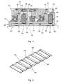
Figure 1 is a cross sectional side elevation of a mechanical face seal incorporating tolerance strips in accordance with the present invention; -
Figure 2 is a perspective view of a length of tolerance strip in accordance with the present invention; -
Figure 3 is a side elevation of the tolerance strip shown infigure 2 ; and -
Figure 4 is a section along the line IV-IV offigure 3 . -
Figure 1 illustrates a typical gas seal having two seal interfaces, aninboard seal interface 10 and anoutboard seal interface 12. Eachseal interface mating ring 14 and aprimary ring 16. Theprimary rings 16 are slidably mounted and sealed with respect to ahousing assembly 18, in known manner. Theprimary rings 16 are fixed rotationally with respect to thehousing assembly 18 and are resiliently urged towards themating rings 14. - The
mating rings 14 are located in fixed axial and rotational relationship on ashaft 20 by means of asleeve assembly 22. Thesleeve assembly 22 has aninner sleeve 24 that is a sliding fit over theshaft 20 and is located axially of theshaft 20 against ashoulder 26. Theinner sleeve member 24 has an outwardly extendingflange formation 28 at its inboard end, the out board face of theflange formation 28 defining anannular recess 30. Themating ring 14 of theinboard seal interface 10 is a sliding fit on theinner sleeve member 24 and locates in theannular recess 30. Asecondary sealing element 32 provides a fluid tight seal between themating ring 14 andflange formation 28. - A first
outer sleeve member 34 is slidingly located on theinner sleeve member 24, the inboard end ofouter sleeve member 34 abutting the outboard face of themating ring 14 of theinboard seal interface 10, to clamp themating ring 14 against theflange formation 28 and locate it axially of theshaft 20. - The out board end of
outer sleeve member 34 has an outwardly extendingflange formation 36, the outboard face of theflange formation 36 defining anannular recess 38. Themating ring 14 of theoutboard seal interface 12 is a sliding fit on theinner sleeve 24 and locates in therecess 38 and is sealed with respect toflange formation 36 bysecondary seal 40. A secondouter sleeve member 42 is a sliding fit over theinner sleeve 24 the inboard end ofsleeve member 42 abutting theoutboard mating ring 14 to clamp it againstflange formation 36. Clamping means (not shown) abuts the outboard end of the secondouter sleeve member 42 to clamp thesleeve assembly 22 axially of theshaft 20 against theshoulder 26.Secondary sealing elements inner sleeve member 24 andshaft 20 and between theinner sleeve member 24 and firstouter sleeve member 34. - In order to accommodate any tolerance variations in the external diameter of the
shaft 20, the internal and external diameters of theinner sleeve member 24 and the internal diameters ofouter sleeve members mating rings 14, and to accommodate any differential expansion of the components, to ensure centring of the components,tolerance strips 50 are located between, theshaft 20 and theinner sleeve 24 and between theinner sleeve 24 and themating rings 14 andouter sleeves tolerance strips 50 are located incircumferential grooves 52 formed in one of each pair of components between which thetolerance strip 50 is located. - As illustrated in greater detail in
figures 2 to 4 thetolerance strip 50 comprises a length of resilient strip of a metallic or alloy material, for example stainless steel. Thestrip 50 is formed withtransverse corrugations 54 that extend across the full width of thestrip 50, thecorrugations 54 defining transversely extendingcrests 56 with transversely extendingtroughs 58 between adjacent corrugations. Thecorrugations 54 have a central portion, the height of which is substantially uniform across the width of thestrip 50. End portions of the corrugations decrease in height towards the longitudinal edges of thestrip 50 to form atapered portion 60. The height oftapered portions 60 at the ends of eachcorrugation 54 are intermediate of the heights of the central portions of thecrests 56 and thetroughs 58. Thecrests 56 andtroughs 58 are substantially flat longitudinally of thestrip 50. - The overall thickness of the
strip 50, from the outer surface of thetroughs 58 to the outer surface of thecrests 56 is designed such that when located in acircumferential groove 52 in one of a pair of opposed surfaces, it will be partially compressed between the surfaces at maximum tolerance and maximum differential expansion, for a particular application. - The width of the
groove 52 is a tolerance fit with the width of thestrip 50, the length of thestrip 50 being sufficiently shorter that the circumference of the surfaces of the components, to permit longitudinal expansion of thestrip 50, when the corrugations are depressed between the opposed surfaces. - In addition, the
tapered portions 60 provide thetolerance strip 50 with longitudinal rigidity, such that during compression the longitudinal expansion of thetolerance strip 50 is controlled and the ends of thetolerance strip 50 are prevented from overlapping each other in thecircumferential groove 52. - The
strip 50 is located in thecircumferential groove 52 of one component, the adjacent components are then assembled together, thetapered portions 60 of the corrugations providing a lead in portion, so that as the components are assembled, thecorrugations 54 will be resiliently compressed between the opposed surfaces of the components. The leading edges of the components that will engage thestrip 50 are also preferably radiused in order to facilitate assembly. - The resilient compression of the
corrugations 54 will take up any tolerance variations in the opposed surfaces of the components and also be compressed and expand with differential thermal expansion of the components, to ensure that the components remain centred over the operating conditions of the assembly. - The flat surfaces of the
crests 56 andtroughs 58, which bear against the opposed surfaces of the components, will spread the loads over relative large areas. Thetolerance strip 50 can consequently be used with components, forexample mating rings 14, made of brittle materials, for example ceramics. - The
tolerance strip 50 may be formed by a pressing process, for example between a pair of rollers. Because the material of thestrip 50 does not yield as much, as compared to tolerance strips formed hitherto, work hardening is minimised and the resilience of the material is maintained. As a consequence the loads required to compress the convolutions will also be reduced. - The
strip 50 does not yield as much because thetapered portions 60 do not fully extend downwardly to the same axis as thetroughs 58. - While in the above embodiment, the
crests 56 andtroughs 58 have longitudinally extending flattened surfaces to spread the compressive loads, only the surface that will bear against the brittle component need be flattened. Alternatively, where the tolerance strip is to be used with components made of strong material, the crests and troughs may be formed as a continuous curve. - While the tolerance strip of the present invention, as described above, is formed by pressing, the strip may alternatively be formed by moulding.
Claims (7)
- A tolerance strip (50) comprising a strip of resilient material formed with corrugations (54), the corrugations (54) extending transversely across the strip (50), the corrugations (54) defining crests (56) with troughs (58) between adjacent crests (56), a central portion of the corrugations (54) being of substantially uniform height across the strip (50), characterised in that the corrugations (54) extend across the full width of the strip (50), portions (60) of the corrugations (54) adjacent each longitudinal edge of the strip (50) decreasing in height towards the edge of the strip (60).
- A tolerance strip (50) according to claim 1 characterised in that the height of the corrugations (54) at the edges of the strip (50) is intermediate of the crests (56) and troughs (58) centrally of the strip (50).
- A tolerance strip (50) according to claim 1 or 2 characterised in that the troughs (58) and/or crests (56) of the corrugations (54) are flat longitudinally of the strip (50).
- A tolerance strip (50) according to any one of the preceding claims characterised in that the strip (50) is formed from a metallic or alloy material.
- A tolerance strip (50) according to any one of the preceding claims characterised in that the strip (50) is formed by pressing.
- A tolerance strip (50) according to claim 5 characterised in that the strip (50) is pressed between shaped rollers.
- A tolerance strip (50) according to any one of claims 1 to 4 characterised in that the strip (50) is formed by moulding.
Applications Claiming Priority (2)
| Application Number | Priority Date | Filing Date | Title |
|---|---|---|---|
| GBGB0903290.5A GB0903290D0 (en) | 2009-02-26 | 2009-02-26 | Tolerance strips |
| PCT/GB2010/000315 WO2010097574A1 (en) | 2009-02-26 | 2010-02-23 | Tolerance strips |
Publications (2)
| Publication Number | Publication Date |
|---|---|
| EP2401535A1 EP2401535A1 (en) | 2012-01-04 |
| EP2401535B1 true EP2401535B1 (en) | 2013-05-29 |
Family
ID=40565772
Family Applications (1)
| Application Number | Title | Priority Date | Filing Date |
|---|---|---|---|
| EP10706714.2A Not-in-force EP2401535B1 (en) | 2009-02-26 | 2010-02-23 | Tolerance strips |
Country Status (5)
| Country | Link |
|---|---|
| US (1) | US8715835B2 (en) |
| EP (1) | EP2401535B1 (en) |
| JP (1) | JP5576887B2 (en) |
| GB (1) | GB0903290D0 (en) |
| WO (1) | WO2010097574A1 (en) |
Families Citing this family (1)
| Publication number | Priority date | Publication date | Assignee | Title |
|---|---|---|---|---|
| US9493301B2 (en) * | 2011-06-03 | 2016-11-15 | Metal Fabricating Corporation | Bin retainer panel |
Family Cites Families (38)
| Publication number | Priority date | Publication date | Assignee | Title |
|---|---|---|---|---|
| US2636968A (en) * | 1953-04-28 | Waiter | ||
| US1681819A (en) * | 1927-09-10 | 1928-08-21 | P H Murphy Co | Railway-car roof |
| US1748772A (en) * | 1927-12-02 | 1930-02-25 | Reeves Mfg Company | Method of making tapered tubular objects |
| US2059292A (en) * | 1933-04-13 | 1936-11-03 | George D Ellis And Sons Inc | Art of working sheet metal |
| US1996004A (en) * | 1933-11-28 | 1935-03-26 | Nat Steel Car Corp Ltd | Corrugated structural unit |
| US2169025A (en) * | 1937-09-16 | 1939-08-08 | Westinghouse Electric & Mfg Co | Method of producing corrugated cases |
| US2217110A (en) * | 1938-04-04 | 1940-10-08 | Standard Railway Equipment Mfg | Railway car construction |
| US2196582A (en) * | 1939-01-04 | 1940-04-09 | Garlock Packing Co | Gasket, gasket-centering means, and assembly thereof |
| US2262086A (en) * | 1940-01-20 | 1941-11-11 | Columbiana Boiler Company | Method of forming corrugated plates |
| AT174257B (en) | 1950-05-10 | 1953-03-10 | Star Kugelhalter Gmbh Dt | Resilient band or resilient rings made of corrugated sheet metal for storing machine parts with any seat type |
| US2833031A (en) * | 1954-11-09 | 1958-05-06 | Columbus Auto Parts | Method of making curved corrugated wedge members |
| US3119446A (en) * | 1959-09-17 | 1964-01-28 | American Thermocatalytic Corp | Heat exchangers |
| US3372963A (en) * | 1965-12-02 | 1968-03-12 | Rotron Mfg Co | Corrugated bearing ring |
| US3633398A (en) | 1970-01-21 | 1972-01-11 | Roller Bearing Co Of America | Making corrugated elastic shims |
| US3961799A (en) | 1975-09-29 | 1976-06-08 | Sealol, Inc. | Conversion kit |
| FR2329371A1 (en) * | 1975-10-28 | 1977-05-27 | Alsthom Cgee | PROCESS FOR MANUFACTURING STRUCTURAL PANELS |
| US4165081A (en) | 1978-04-14 | 1979-08-21 | The United States Of America As Represented By The Secretary Of The Army | Constant force face seal |
| US4274683A (en) | 1978-12-29 | 1981-06-23 | Mechanical Technology Incorporated | Support element for compliant hydrodynamic journal bearings |
| US4241664A (en) * | 1979-03-13 | 1980-12-30 | Weld Tooling Corporation | Formable drive rails |
| US4286894A (en) * | 1979-03-21 | 1981-09-01 | Roller Bearing Company Of America | Tolerance rings |
| DE3428744A1 (en) * | 1983-08-12 | 1985-02-28 | Dickow-Pumpen KG, 8264 Waldkraiburg | Fixing of annular silicon-carbide components on metal supporting parts |
| US4762743A (en) * | 1987-07-31 | 1988-08-09 | Bio-Rad Laboratories, Inc. | Corrugated wedge spacers for slab gel molds |
| SU1609963A1 (en) * | 1988-02-10 | 1990-11-30 | Северо-Кавказский Государственный Научно-Исследовательский И Проектный Институт Нефтяной Промышленности | Sealing member of packer |
| US5039113A (en) | 1990-01-17 | 1991-08-13 | Eg&G Sealol, Inc. | Spiral groove gas lubricated seal |
| JPH0756344B2 (en) * | 1991-09-09 | 1995-06-14 | 日本ピラー工業株式会社 | mechanical seal |
| SE470229B (en) * | 1991-09-20 | 1993-12-13 | Jan Gunnar Sergenius | Material in the form of tape, sheet, foil, sheet, sheet or equivalent, which is provided with stiffening corrugation or embossing |
| JPH05141461A (en) * | 1991-10-23 | 1993-06-08 | F Pureba Walter | Improved spring uniformly withstanding load |
| US5533739A (en) | 1992-06-10 | 1996-07-09 | Durametallic Corporation | Non-contacting seal with centering spring mounted in dovetailed grooved |
| US5388843A (en) * | 1993-02-16 | 1995-02-14 | Durametallic Corporation | Fluid film seal |
| DE69629366D1 (en) | 1995-03-31 | 2003-09-11 | Crane John Inc | MECHANICAL SEAL WITH FLEXIBLE METAL MEMBRANE |
| US6314664B1 (en) | 1997-04-18 | 2001-11-13 | Mizuno Corporation | Athletic shoe midsole design and construction |
| JP3692239B2 (en) * | 1998-04-16 | 2005-09-07 | 三菱重工業株式会社 | Dry gas seal |
| JP4426049B2 (en) | 1999-03-31 | 2010-03-03 | エドワーズ株式会社 | Magnetic bearing device and vacuum pump |
| US7625023B2 (en) * | 2000-02-07 | 2009-12-01 | Oakwood Energy Management, Inc. | Modular energy absorber with ribbed wall structure |
| US7704292B2 (en) * | 2003-12-17 | 2010-04-27 | Ruihua Hu | Fluid filter |
| EP1693635A1 (en) * | 2005-02-22 | 2006-08-23 | Vesuvius Crucible Company | Ceramic conveyor roll with metal end caps and its assembly |
| JP2007327577A (en) * | 2006-06-08 | 2007-12-20 | Toyota Motor Corp | Mechanical pump |
| US7554771B2 (en) * | 2006-09-11 | 2009-06-30 | Intri-Plex Technologies, Inc. | Tolerance ring for data storage with overlapping tab feature for mass control |
-
2009
- 2009-02-26 GB GBGB0903290.5A patent/GB0903290D0/en not_active Ceased
-
2010
- 2010-02-23 EP EP10706714.2A patent/EP2401535B1/en not_active Not-in-force
- 2010-02-23 US US13/202,514 patent/US8715835B2/en not_active Expired - Fee Related
- 2010-02-23 JP JP2011551516A patent/JP5576887B2/en not_active Expired - Fee Related
- 2010-02-23 WO PCT/GB2010/000315 patent/WO2010097574A1/en not_active Ceased
Also Published As
| Publication number | Publication date |
|---|---|
| US8715835B2 (en) | 2014-05-06 |
| WO2010097574A1 (en) | 2010-09-02 |
| US20110300399A1 (en) | 2011-12-08 |
| JP5576887B2 (en) | 2014-08-20 |
| GB0903290D0 (en) | 2009-04-08 |
| JP2012518768A (en) | 2012-08-16 |
| EP2401535A1 (en) | 2012-01-04 |
Similar Documents
| Publication | Publication Date | Title |
|---|---|---|
| JP5591896B2 (en) | Sealing device | |
| US6352267B1 (en) | Adjustaby sizeable ring seal | |
| EP3312482B1 (en) | Seal assemblies for extreme temperatures and related methods | |
| CN105308370B (en) | sealing ring | |
| KR101920619B1 (en) | Tolerance ring with divided torque slip | |
| EP0939265A2 (en) | Metal hose fitting and method of making | |
| JPS6065959A (en) | Seal ring for piston rod | |
| EP2857720B1 (en) | Combined oil control ring | |
| US5520092A (en) | Piston of shock absorber | |
| CN108431467B (en) | Multi-piece oil controlled piston rings with reduced friction | |
| CA2716934A1 (en) | Hoop retaining ring | |
| US5380015A (en) | Machined shaft seal encased in an elastomeric sleeve | |
| US8715835B2 (en) | Tolerance strips | |
| JP2007071329A (en) | Back-up ring | |
| US11566710B2 (en) | Seals | |
| US9845876B2 (en) | Gasket and method of producing gasket | |
| KR102576874B1 (en) | Sealing device and installation method of the sealing device | |
| CN105987083B (en) | Bearing and sealing method thereof | |
| EP2923096B1 (en) | Bearing shell with alignment projecting feature | |
| EP3205909B1 (en) | Oil ring | |
| US10323753B2 (en) | Gasket seal seat ring | |
| KR101919648B1 (en) | Static gasket with wire compression limiter | |
| EP4217627B1 (en) | Pressure retained gasket seal with enhanced unloading resistance | |
| JP7475778B2 (en) | Metal Gasket | |
| GB2235260A (en) | Seals |
Legal Events
| Date | Code | Title | Description |
|---|---|---|---|
| PUAI | Public reference made under article 153(3) epc to a published international application that has entered the european phase |
Free format text: ORIGINAL CODE: 0009012 |
|
| 17P | Request for examination filed |
Effective date: 20110916 |
|
| AK | Designated contracting states |
Kind code of ref document: A1 Designated state(s): AT BE BG CH CY CZ DE DK EE ES FI FR GB GR HR HU IE IS IT LI LT LU LV MC MK MT NL NO PL PT RO SE SI SK SM TR |
|
| DAX | Request for extension of the european patent (deleted) | ||
| 17Q | First examination report despatched |
Effective date: 20120615 |
|
| GRAP | Despatch of communication of intention to grant a patent |
Free format text: ORIGINAL CODE: EPIDOSNIGR1 |
|
| GRAS | Grant fee paid |
Free format text: ORIGINAL CODE: EPIDOSNIGR3 |
|
| GRAA | (expected) grant |
Free format text: ORIGINAL CODE: 0009210 |
|
| AK | Designated contracting states |
Kind code of ref document: B1 Designated state(s): AT BE BG CH CY CZ DE DK EE ES FI FR GB GR HR HU IE IS IT LI LT LU LV MC MK MT NL NO PL PT RO SE SI SK SM TR |
|
| REG | Reference to a national code |
Ref country code: GB Ref legal event code: FG4D |
|
| REG | Reference to a national code |
Ref country code: CH Ref legal event code: EP |
|
| REG | Reference to a national code |
Ref country code: AT Ref legal event code: REF Ref document number: 614620 Country of ref document: AT Kind code of ref document: T Effective date: 20130615 |
|
| REG | Reference to a national code |
Ref country code: IE Ref legal event code: FG4D |
|
| REG | Reference to a national code |
Ref country code: DE Ref legal event code: R096 Ref document number: 602010007326 Country of ref document: DE Effective date: 20130725 |
|
| REG | Reference to a national code |
Ref country code: AT Ref legal event code: MK05 Ref document number: 614620 Country of ref document: AT Kind code of ref document: T Effective date: 20130529 |
|
| REG | Reference to a national code |
Ref country code: LT Ref legal event code: MG4D |
|
| PG25 | Lapsed in a contracting state [announced via postgrant information from national office to epo] |
Ref country code: NO Free format text: LAPSE BECAUSE OF FAILURE TO SUBMIT A TRANSLATION OF THE DESCRIPTION OR TO PAY THE FEE WITHIN THE PRESCRIBED TIME-LIMIT Effective date: 20130829 Ref country code: SE Free format text: LAPSE BECAUSE OF FAILURE TO SUBMIT A TRANSLATION OF THE DESCRIPTION OR TO PAY THE FEE WITHIN THE PRESCRIBED TIME-LIMIT Effective date: 20130529 Ref country code: ES Free format text: LAPSE BECAUSE OF FAILURE TO SUBMIT A TRANSLATION OF THE DESCRIPTION OR TO PAY THE FEE WITHIN THE PRESCRIBED TIME-LIMIT Effective date: 20130909 Ref country code: AT Free format text: LAPSE BECAUSE OF FAILURE TO SUBMIT A TRANSLATION OF THE DESCRIPTION OR TO PAY THE FEE WITHIN THE PRESCRIBED TIME-LIMIT Effective date: 20130529 Ref country code: GR Free format text: LAPSE BECAUSE OF FAILURE TO SUBMIT A TRANSLATION OF THE DESCRIPTION OR TO PAY THE FEE WITHIN THE PRESCRIBED TIME-LIMIT Effective date: 20130830 Ref country code: PT Free format text: LAPSE BECAUSE OF FAILURE TO SUBMIT A TRANSLATION OF THE DESCRIPTION OR TO PAY THE FEE WITHIN THE PRESCRIBED TIME-LIMIT Effective date: 20130930 Ref country code: LT Free format text: LAPSE BECAUSE OF FAILURE TO SUBMIT A TRANSLATION OF THE DESCRIPTION OR TO PAY THE FEE WITHIN THE PRESCRIBED TIME-LIMIT Effective date: 20130529 Ref country code: FI Free format text: LAPSE BECAUSE OF FAILURE TO SUBMIT A TRANSLATION OF THE DESCRIPTION OR TO PAY THE FEE WITHIN THE PRESCRIBED TIME-LIMIT Effective date: 20130529 Ref country code: IS Free format text: LAPSE BECAUSE OF FAILURE TO SUBMIT A TRANSLATION OF THE DESCRIPTION OR TO PAY THE FEE WITHIN THE PRESCRIBED TIME-LIMIT Effective date: 20130929 Ref country code: SI Free format text: LAPSE BECAUSE OF FAILURE TO SUBMIT A TRANSLATION OF THE DESCRIPTION OR TO PAY THE FEE WITHIN THE PRESCRIBED TIME-LIMIT Effective date: 20130529 |
|
| REG | Reference to a national code |
Ref country code: NL Ref legal event code: VDEP Effective date: 20130529 |
|
| PG25 | Lapsed in a contracting state [announced via postgrant information from national office to epo] |
Ref country code: PL Free format text: LAPSE BECAUSE OF FAILURE TO SUBMIT A TRANSLATION OF THE DESCRIPTION OR TO PAY THE FEE WITHIN THE PRESCRIBED TIME-LIMIT Effective date: 20130529 Ref country code: HR Free format text: LAPSE BECAUSE OF FAILURE TO SUBMIT A TRANSLATION OF THE DESCRIPTION OR TO PAY THE FEE WITHIN THE PRESCRIBED TIME-LIMIT Effective date: 20130529 Ref country code: BG Free format text: LAPSE BECAUSE OF FAILURE TO SUBMIT A TRANSLATION OF THE DESCRIPTION OR TO PAY THE FEE WITHIN THE PRESCRIBED TIME-LIMIT Effective date: 20130829 |
|
| PG25 | Lapsed in a contracting state [announced via postgrant information from national office to epo] |
Ref country code: LV Free format text: LAPSE BECAUSE OF FAILURE TO SUBMIT A TRANSLATION OF THE DESCRIPTION OR TO PAY THE FEE WITHIN THE PRESCRIBED TIME-LIMIT Effective date: 20130529 |
|
| PG25 | Lapsed in a contracting state [announced via postgrant information from national office to epo] |
Ref country code: BE Free format text: LAPSE BECAUSE OF FAILURE TO SUBMIT A TRANSLATION OF THE DESCRIPTION OR TO PAY THE FEE WITHIN THE PRESCRIBED TIME-LIMIT Effective date: 20130529 Ref country code: SK Free format text: LAPSE BECAUSE OF FAILURE TO SUBMIT A TRANSLATION OF THE DESCRIPTION OR TO PAY THE FEE WITHIN THE PRESCRIBED TIME-LIMIT Effective date: 20130529 Ref country code: DK Free format text: LAPSE BECAUSE OF FAILURE TO SUBMIT A TRANSLATION OF THE DESCRIPTION OR TO PAY THE FEE WITHIN THE PRESCRIBED TIME-LIMIT Effective date: 20130529 Ref country code: CZ Free format text: LAPSE BECAUSE OF FAILURE TO SUBMIT A TRANSLATION OF THE DESCRIPTION OR TO PAY THE FEE WITHIN THE PRESCRIBED TIME-LIMIT Effective date: 20130529 Ref country code: EE Free format text: LAPSE BECAUSE OF FAILURE TO SUBMIT A TRANSLATION OF THE DESCRIPTION OR TO PAY THE FEE WITHIN THE PRESCRIBED TIME-LIMIT Effective date: 20130529 |
|
| PG25 | Lapsed in a contracting state [announced via postgrant information from national office to epo] |
Ref country code: RO Free format text: LAPSE BECAUSE OF FAILURE TO SUBMIT A TRANSLATION OF THE DESCRIPTION OR TO PAY THE FEE WITHIN THE PRESCRIBED TIME-LIMIT Effective date: 20130529 Ref country code: NL Free format text: LAPSE BECAUSE OF FAILURE TO SUBMIT A TRANSLATION OF THE DESCRIPTION OR TO PAY THE FEE WITHIN THE PRESCRIBED TIME-LIMIT Effective date: 20130529 |
|
| PLBE | No opposition filed within time limit |
Free format text: ORIGINAL CODE: 0009261 |
|
| STAA | Information on the status of an ep patent application or granted ep patent |
Free format text: STATUS: NO OPPOSITION FILED WITHIN TIME LIMIT |
|
| 26N | No opposition filed |
Effective date: 20140303 |
|
| REG | Reference to a national code |
Ref country code: DE Ref legal event code: R097 Ref document number: 602010007326 Country of ref document: DE Effective date: 20140303 |
|
| PG25 | Lapsed in a contracting state [announced via postgrant information from national office to epo] |
Ref country code: MC Free format text: LAPSE BECAUSE OF FAILURE TO SUBMIT A TRANSLATION OF THE DESCRIPTION OR TO PAY THE FEE WITHIN THE PRESCRIBED TIME-LIMIT Effective date: 20130529 Ref country code: LU Free format text: LAPSE BECAUSE OF FAILURE TO SUBMIT A TRANSLATION OF THE DESCRIPTION OR TO PAY THE FEE WITHIN THE PRESCRIBED TIME-LIMIT Effective date: 20140223 |
|
| REG | Reference to a national code |
Ref country code: CH Ref legal event code: PL |
|
| PG25 | Lapsed in a contracting state [announced via postgrant information from national office to epo] |
Ref country code: CH Free format text: LAPSE BECAUSE OF NON-PAYMENT OF DUE FEES Effective date: 20140228 Ref country code: LI Free format text: LAPSE BECAUSE OF NON-PAYMENT OF DUE FEES Effective date: 20140228 |
|
| REG | Reference to a national code |
Ref country code: DE Ref legal event code: R082 Ref document number: 602010007326 Country of ref document: DE Representative=s name: FRIESE GOEDEN PATENTANWAELTE PARTGMBB, DE Ref country code: DE Ref legal event code: R082 Ref document number: 602010007326 Country of ref document: DE Representative=s name: ANDRAE WESTENDORP PATENTANWAELTE PARTNERSCHAFT, DE |
|
| REG | Reference to a national code |
Ref country code: IE Ref legal event code: MM4A |
|
| PG25 | Lapsed in a contracting state [announced via postgrant information from national office to epo] |
Ref country code: IE Free format text: LAPSE BECAUSE OF NON-PAYMENT OF DUE FEES Effective date: 20140223 |
|
| REG | Reference to a national code |
Ref country code: FR Ref legal event code: PLFP Year of fee payment: 7 |
|
| PG25 | Lapsed in a contracting state [announced via postgrant information from national office to epo] |
Ref country code: MT Free format text: LAPSE BECAUSE OF FAILURE TO SUBMIT A TRANSLATION OF THE DESCRIPTION OR TO PAY THE FEE WITHIN THE PRESCRIBED TIME-LIMIT Effective date: 20130529 |
|
| PG25 | Lapsed in a contracting state [announced via postgrant information from national office to epo] |
Ref country code: SM Free format text: LAPSE BECAUSE OF FAILURE TO SUBMIT A TRANSLATION OF THE DESCRIPTION OR TO PAY THE FEE WITHIN THE PRESCRIBED TIME-LIMIT Effective date: 20130529 |
|
| PGFP | Annual fee paid to national office [announced via postgrant information from national office to epo] |
Ref country code: DE Payment date: 20160216 Year of fee payment: 7 Ref country code: IT Payment date: 20160222 Year of fee payment: 7 |
|
| PGFP | Annual fee paid to national office [announced via postgrant information from national office to epo] |
Ref country code: GB Payment date: 20160217 Year of fee payment: 7 Ref country code: FR Payment date: 20160108 Year of fee payment: 7 |
|
| PG25 | Lapsed in a contracting state [announced via postgrant information from national office to epo] |
Ref country code: CY Free format text: LAPSE BECAUSE OF FAILURE TO SUBMIT A TRANSLATION OF THE DESCRIPTION OR TO PAY THE FEE WITHIN THE PRESCRIBED TIME-LIMIT Effective date: 20130529 |
|
| PG25 | Lapsed in a contracting state [announced via postgrant information from national office to epo] |
Ref country code: TR Free format text: LAPSE BECAUSE OF FAILURE TO SUBMIT A TRANSLATION OF THE DESCRIPTION OR TO PAY THE FEE WITHIN THE PRESCRIBED TIME-LIMIT Effective date: 20130529 Ref country code: HU Free format text: LAPSE BECAUSE OF FAILURE TO SUBMIT A TRANSLATION OF THE DESCRIPTION OR TO PAY THE FEE WITHIN THE PRESCRIBED TIME-LIMIT; INVALID AB INITIO Effective date: 20100223 |
|
| REG | Reference to a national code |
Ref country code: DE Ref legal event code: R082 Ref document number: 602010007326 Country of ref document: DE Representative=s name: FRIESE GOEDEN PATENTANWAELTE PARTGMBB, DE |
|
| REG | Reference to a national code |
Ref country code: DE Ref legal event code: R119 Ref document number: 602010007326 Country of ref document: DE |
|
| GBPC | Gb: european patent ceased through non-payment of renewal fee |
Effective date: 20170223 |
|
| REG | Reference to a national code |
Ref country code: FR Ref legal event code: ST Effective date: 20171031 |
|
| PG25 | Lapsed in a contracting state [announced via postgrant information from national office to epo] |
Ref country code: DE Free format text: LAPSE BECAUSE OF NON-PAYMENT OF DUE FEES Effective date: 20170901 Ref country code: FR Free format text: LAPSE BECAUSE OF NON-PAYMENT OF DUE FEES Effective date: 20170228 |
|
| PG25 | Lapsed in a contracting state [announced via postgrant information from national office to epo] |
Ref country code: IT Free format text: LAPSE BECAUSE OF NON-PAYMENT OF DUE FEES Effective date: 20170223 Ref country code: GB Free format text: LAPSE BECAUSE OF NON-PAYMENT OF DUE FEES Effective date: 20170223 |
|
| PG25 | Lapsed in a contracting state [announced via postgrant information from national office to epo] |
Ref country code: MK Free format text: LAPSE BECAUSE OF FAILURE TO SUBMIT A TRANSLATION OF THE DESCRIPTION OR TO PAY THE FEE WITHIN THE PRESCRIBED TIME-LIMIT Effective date: 20130529 |
|
| P01 | Opt-out of the competence of the unified patent court (upc) registered |
Effective date: 20230523 |