EP2400741A1 - Image processing device, method, and program - Google Patents
Image processing device, method, and program Download PDFInfo
- Publication number
- EP2400741A1 EP2400741A1 EP10743751A EP10743751A EP2400741A1 EP 2400741 A1 EP2400741 A1 EP 2400741A1 EP 10743751 A EP10743751 A EP 10743751A EP 10743751 A EP10743751 A EP 10743751A EP 2400741 A1 EP2400741 A1 EP 2400741A1
- Authority
- EP
- European Patent Office
- Prior art keywords
- noise
- model
- image
- value region
- capturing
- Prior art date
- Legal status (The legal status is an assumption and is not a legal conclusion. Google has not performed a legal analysis and makes no representation as to the accuracy of the status listed.)
- Granted
Links
Images


Classifications
-
- A—HUMAN NECESSITIES
- A61—MEDICAL OR VETERINARY SCIENCE; HYGIENE
- A61B—DIAGNOSIS; SURGERY; IDENTIFICATION
- A61B1/00—Instruments for performing medical examinations of the interior of cavities or tubes of the body by visual or photographical inspection, e.g. endoscopes; Illuminating arrangements therefor
- A61B1/04—Instruments for performing medical examinations of the interior of cavities or tubes of the body by visual or photographical inspection, e.g. endoscopes; Illuminating arrangements therefor combined with photographic or television appliances
-
- G—PHYSICS
- G06—COMPUTING OR CALCULATING; COUNTING
- G06T—IMAGE DATA PROCESSING OR GENERATION, IN GENERAL
- G06T5/00—Image enhancement or restoration
- G06T5/70—Denoising; Smoothing
-
- H—ELECTRICITY
- H04—ELECTRIC COMMUNICATION TECHNIQUE
- H04N—PICTORIAL COMMUNICATION, e.g. TELEVISION
- H04N23/00—Cameras or camera modules comprising electronic image sensors; Control thereof
- H04N23/60—Control of cameras or camera modules
-
- H—ELECTRICITY
- H04—ELECTRIC COMMUNICATION TECHNIQUE
- H04N—PICTORIAL COMMUNICATION, e.g. TELEVISION
- H04N23/00—Cameras or camera modules comprising electronic image sensors; Control thereof
- H04N23/60—Control of cameras or camera modules
- H04N23/667—Camera operation mode switching, e.g. between still and video, sport and normal or high- and low-resolution modes
-
- H—ELECTRICITY
- H04—ELECTRIC COMMUNICATION TECHNIQUE
- H04N—PICTORIAL COMMUNICATION, e.g. TELEVISION
- H04N23/00—Cameras or camera modules comprising electronic image sensors; Control thereof
- H04N23/80—Camera processing pipelines; Components thereof
- H04N23/81—Camera processing pipelines; Components thereof for suppressing or minimising disturbance in the image signal generation
-
- G—PHYSICS
- G06—COMPUTING OR CALCULATING; COUNTING
- G06T—IMAGE DATA PROCESSING OR GENERATION, IN GENERAL
- G06T2207/00—Indexing scheme for image analysis or image enhancement
- G06T2207/20—Special algorithmic details
- G06T2207/20004—Adaptive image processing
- G06T2207/20012—Locally adaptive
Definitions
- the present invention relates to an image processing apparatus, an image processing method, and an image processing program that are suitable for performing noise reduction of input image signals.
- Patent Literature 1 As a method of reducing noise in video signals, a method has been proposed in which generated noise levels are modeled, noise levels generated in input video signals are estimated on the basis of the noise model, and then noise reduction processing is performed. For example, in Patent Literature 1, a method is proposed in which a noise level is calculated on the basis of input video signals and a reference noise model.
- the present invention has been conceived in order to solve the above-described problems, and an object thereof is to provide an image processing apparatus, an image processing method, and an image processing program that are capable of creating a difference in noise reduction between a predetermined signal-value region, such as a dark part, etc., and other regions.
- a first aspect of the present invention is an image processing apparatus including image-capturing-mode selecting means for selecting one image-capturing mode from a plurality of image-capturing modes; and noise-reduction processing means for performing noise reduction processing on input image signals by employing, in the case in which an image-capturing mode selected by the image-capturing-mode selecting means is a specific image-capturing mode, an applied noise model in which a noise model for a predetermined signal-value region differs from a reference noise model determined on the basis of properties of an image-acquisition element.
- a second aspect of the present invention is an image processing program for causing a computer to execute, image-capturing-mode selecting processing for selecting one image-capturing mode from a plurality of image-capturing modes; and noise-reduction processing for performing noise reduction processing on input image signals by employing, in the case in which the selected image-capturing mode is a specific image-capturing mode, an applied noise model in which a noise model for a predetermined signal-value region differs from a reference noise model determined on the basis of properties of an image-acquisition element.
- a third aspect of the present invention is an image processing method including a step of selecting one image-capturing mode from a plurality of image-capturing modes; and a step of performing noise reduction processing on input image signals by employing, in the case in which the selected image-capturing mode is a specific image-capturing mode, an applied noise model in which a noise model for a predetermined signal-value region differs from a reference noise model determined on the basis of properties of an image-acquisition element.
- the present invention affords an advantage in that noise reduction in a dark part can be improved.
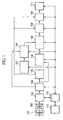
- Fig. 1 is a block diagram showing an example configuration of an image acquisition system according to a first embodiment of the present invention.
- the image acquisition system according to this embodiment is, for example, a digital camera and is provided with an image acquisition apparatus, which includes a lens system 101 and a CCD 102, and an image processing apparatus that applies various kinds of image processing, such as noise-reduction processing, etc., to image signals acquired by the image acquisition apparatus.
- an A/D converter 103 is connected to an image-capturing-mode selecting portion 104.
- the image-capturing-mode selecting portion 104 is connected to a buffer 105 and a signal-value-region setting portion 106.
- the buffer 105 is connected to a noise-level calculating portion 109 and a noise-reduction processing portion 110.
- the signal-value-region setting portion 106 is connected to an applied-noise-model setting portion 108.
- a reference-noise-model storing portion 107 is connected to a reference-noise-model selecting portion 114.
- the reference-noise-model selecting portion 114 is connected to an applied-noise-model setting portion 108.
- the applied-noise-model setting portion 108 is connected to the noise-level calculating portion 109.
- the noise-level calculating portion 109 is connected to the noise-reduction processing portion 110.
- the noise-reduction processing portion 110 is connected to an output portion 111.
- a controller 112 such as a microcomputer, is bidirectionally connected to the A/D converter 103, the image-capturing-mode selecting portion 104, the signal-value-region setting portion 106, the reference-noise-model storing portion 107, the applied-noise-model setting portion 108, the noise-level calculating portion 109, the noise-reduction processing portion 110, and the output portion 111.
- an external interface (hereinafter, abbreviated as I/F) portion 113 provided with a power switch and an interface for setting variables is also bidirectionally connected to the controller 112.
- the A/D converter 103 converts analog image signals input via the lens system 101 and the CCD (image acquisition element) 102 and outputs the input image signals that have been converted to digital image signals to the image-capturing-mode selecting portion 104.
- the image-capturing-mode selecting portion 104 possesses a plurality of image-capturing modes in advance and, from these, selects an image-capturing mode input by a user via the external I/F portion 113. Furthermore, the image-capturing-mode selecting portion 104 applies image processing to the input image signals acquired from the A/D converter 103 in accordance with the selected image-capturing mode and outputs the processed signals to the signal-value-region setting portion 106 and the buffer 105.
- the image-capturing modes include modes such as a firework mode and a night-view mode that are suitable for capturing subjects with a large brightness difference.
- the buffer 105 temporarily stores the image signals to which the image processing in accordance with the image-capturing mode has been applied and information about the image-capturing mode and outputs the processed image signals and the information to the noise-level calculating portion 109 and the noise-reduction processing portion 110.
- the signal-value-region setting portion 106 possesses information in which the image-capturing modes are associated with thresholds for setting a signal-value region, and, only when an image-capturing mode selected by the image-capturing-mode selecting portion 104 corresponds to a specific image-capturing mode, the signal-value-region setting portion 106 extracts a threshold corresponding to the image-capturing mode, sets a signal-value region at or below the threshold as a predetermined signal-value region, and outputs this information to the applied-noise-model setting portion 108.
- the image-capturing mode selected by the image-capturing-mode selecting portion 104 does not correspond to a pre-registered specific image-capturing mode, the information about the predetermined signal-value region is not output to the applied-noise-model setting portion 108 from the signal-value-region setting portion 106.
- the reference-noise-model storing portion 107 stores a plurality of reference noise models determined by the properties of the CCD 102. Specifically, a reference noise model stores a reference noise model corresponding to the type and image-capturing mode of the CCD 102.
- Fig. 3 shows an example of the reference noise model. In Fig. 3 , the horizontal axis is signal value and the vertical axis is noise level, and Fig. 3 shows that the noise level increases with an increase in the signal value.
- the reference-noise-model selecting portion 114 selects a reference noise model that corresponds to the CCD 102 and the image-capturing mode used when the input image signals are acquired.
- the reference noise model selected by the reference-noise-model selecting portion 114 is output to the applied-noise-model setting portion 108.
- the applied-noise-model setting portion 108 changes teh noise model for the predetermined signal-value region in the reference noise model that has been input from the reference-noise-model selecting portion 114, and sets this as an applied noise model. Accordingly, it becomes possible to set an applied noise model in which the noise model for the predetermined signal-value region is different from the noise model for a signal-value region other than the predetermined signal-value region. At this time, the applied-noise-model setting portion 108 also sets the applied noise model so that noise levels at boundary between the predetermined signal-value region and the signal-value region other than the predetermined signal-value region are matched.
- the applied-noise-model setting portion 108 outputs a reference noise model that has been input from the reference-noise-model selecting portion 114 to the noise-level calculating portion 109 without modification.
- the applied-noise-model setting portion 108 will be described below in detail, using Fig. 2 .
- the applied-noise-model setting portion 108 is formed of a function setting portion 301 and an applied-noise-model creating portion 302.
- the function setting portion 301 sets a function for transforming the noise model for the predetermined signal-value region in the reference noise model acquired from the reference-noise-model selecting portion 114. This function is given by the following Expression (1).
- f(x)' is a noise model after the transformation
- f(x) is a reference noise model before the transformation
- ⁇ is a negative coefficient
- ⁇ is a positive coefficient
- the above-described Expression (1) is, for example, represented as shown in Fig. 5 .
- the above-described Expression (1) is a function in which a reference noise model acquired from the reference-noise selecting portion 114 is multiplied by the negative coefficient ⁇ , and the positive value ⁇ is added thereto.
- the negative coefficient ⁇ and the positive value ⁇ may be such that the user can set them through the external I/F portion 113 or may be predefined in accordance with the image image-capturing mode.
- the applied-noise-model creating portion 302 uses the function expressed by the above-described Expression (1) set by the function setting portion 301 to transform the noise model for the predetermined signal-value region in the reference noise model, and thereby creates an applied noise model. Accordingly, the applied noise model becomes a noise model in which the noise model for the predetermined signal-value region is expressed as the above-described function and in which the reference noise model is employed, without modification, as the noise model for the signal-value region other than the predetermined signal-value region. At this time, the applied-noise-model creating portion 302 creates the applied noise model so that noise levels at boundary between the predetermined signal-value region and the signal-value region other than the predetermined signal-value region are matched.
- the applied noise model created in this way is output to the noise-level calculating portion 109.
- the applied-noise-model setting portion 108 outputs the reference noise model that has been input from the reference-noise-model selecting portion 114 to the noise-level calculating portion 109 without performing the above-described setting processing for the applied noise model.
- the noise-level calculating portion 109 calculates a noise level for each signal value on the basis of the applied noise model set by the applied-noise-model setting portion 108, and outputs it to the noise-reduction processing portion 110.
- the noise-reduction processing portion 110 reads out the input image signals stored in the buffer 105 and applies noise-reduction processing to the input image signals on the basis of the noise levels calculated by the noise-level calculating portion 109. Image signals to which the noise-reduction processing has been applied are output to the output portion 111.
- the output portion 111 stores and saves the image signals to which the noise-reduction processing has been applied by the noise-reduction processing portion 110 in a storage medium such as a memory card or the like.
- image-capturing is performed by the user after image-capturing conditions, such as image-acquisition size, etc. are set via the external I/F portion 113, optical information about a subject is converted to analog image signals by the lens system 101 and the CCD 102, and the signals are input to the A/D converter 103.
- the input image signals which are analog signals input to the A/D converter 103, are converted to digital image signals and the converted input image signals are output to the image-capturing-mode selecting portion 104.
- the image-capturing mode at the time of acquiring the input image signals is determined, and image processing in accordance with the this image-capturing mode is applied to the input image signals.
- the input image signals after the image processing are output to the buffer 105, the signal-value-region setting portion 106, and the reference-noise-model selecting portion 114 along with the information about the image-capturing mode.
- the information about the image-capturing mode and the input image signals are temporarily stored and are then output to the noise-level calculating portion 109 and the noise-reduction processing portion 110.
- the signal-value-region setting portion 106 in the case in which the image-capturing mode selected by the image-capturing-mode selecting portion 104 is the specific image-capturing mode, a predetermined signal-value region that corresponds to this image-capturing mode is selected and output to the applied-noise-model setting portion 108.
- a reference noise model corresponding to the CCD 102 is extracted from the reference-noise-model storing portion 107 and output to the applied-noise-model setting portion 108.
- the noise model for the predetermined signal-value region is transformed with the function expressed as the above-described Expression (1), thereby creating an applied noise model, and this applied noise model is output to the noise-level calculating portion 109.
- the applied-noise-model creating processing is not performed by the applied-noise-model setting portion 108, and the reference noise model input from the reference-noise-model selecting portion 114 is output to the noise-level calculating portion 109 without modification.
- noise levels are calculated on the basis of the applied noise model set by the applied-noise-model setting portion 108, and the calculated noise levels are output to the noise-reduction processing portion 110.
- noise-reduction processing portion 110 noise-reduction processing is applied to the input image signals, which have temporarily been stored in the buffer 105, on the basis of the noise levels calculated by the noise-level calculating portion 109, and the image signals to which the noise-reduction processing has been applied are output to the output portion 111.
- the image signals to which the noise-reduction processing has been applied are stored and saved in a storage medium such as a memory card, or the like.
- an image acquisition system that is integrated with the image acquisition apparatus provided with the lens system 101 and the CCD 102 has been described; however, the system need not be limited to such a configuration, and the image acquisition apparatus may be separately provided.
- image signals acquired by a separate image-acquisition apparatus and stored in a storage medium, such as a memory card, or the like, in the form of unprocessed raw data may be read out from the storage medium and processed by an image processing apparatus.
- information about image capturing ISO speed, white balance factor, etc.
- transmission of various information from the separate image-acquisition apparatus to the image-signal processing apparatus is not limited to transmission via the storage medium, and it may be performed via a communication circuit, etc.
- image-signal processing is assumed to be performed by hardware; however, it need not be limited to such a configuration.
- signals from the CCD 102 may be stored in a computer-readable storage medium, such as a memory card, or the like, as unprocessed raw data, and the information about image-capturing (ISO speed, white balance factor, etc.) from the controller 112 may also be stored in the storage medium as header information.
- an image-signal processing program which is separate software
- transmission of various information from the image-acquisition apparatus to the computer is not limited to the transmission via the storage medium, as with the case described above, and the transmission may be performed via a communication circuit, etc.
- Fig. 9 is a diagram showing the operation flow with regard to the image-signal processing realized by the above-described image processing apparatus.
- Step SA 1-1 when input image signals and header information are input (Step SA 1-1), an image-capturing mode is selected on the basis of this header information (Step SA 1-2). Subsequently, a reference noise model corresponding to the image-capturing mode selected in Step SA 1-2 is set (Step SA 1-3), and, furthermore, a signal-value region is set (Step SA 1-4).
- an applied noise model is set by using the reference noise model selected in Step SA 1-3 and the predetermined signal-value region set in Step SA 1-4 (Step SA 1-5); noise levels of the input image signals are calculated by using the applied noise model (Step SA 1-6); and noise-reduction processing is performed on the basis of the calculated noise level (Step SA 1-7).
- the noise-reduced image signals that have been processed in Step SA 1-7 are output, and this processing is completed (Step SA 1-8).
- Fig. 10 shows the operation flow with regard to the applied-noise-model setting processing in the above-described Steps SA 1-5.
- a function for transforming the reference noise model is set (Step SA 2-1).
- an applied noise model is created by using the function set in Step SA 2-1 (Step SA 2-2).
- the noise model for the predetermined signal-value region and the noise model for a signal-value region other than the predetermined signal-value region are different, it becomes possible to create a difference in noise reduction between the predetermined signal-value region and the signal-value region other than the predetermined signal-value region. Accordingly, noise-reduction processing can be more reliably applied to the predetermined signal-value region among the input image signals, such as a dark part, etc., in accordance with the image-capturing mode, and it becomes possible to perform optimal noise-reduction processing for the input image signals.
- the function setting portion is configured to set a function such as one expressed as the above-described Expression (1); however, this function is not limited to this example.
- a function in which the noise level in the predetermined signal-value region is set to be constant at f(i), as represented by Expression (2) below, may be set.
- f(x)' is a converted noise model
- f(i) is a noise level of a reference noise model at boundary i between a predetermined signal-value region and signal-value region other than the predetermined signal-value region.
- the reference noise model is assumed to be continuous values expressed by a function; however, it is not limited to this example.
- a reference noise model may be expressed by a plurality of discrete signal values, information about noise levels for these signal values, and information about the inclination of a straight line that connects the noise levels.
- Such a reference noise model is expressed, for example, as shown in Fig. 6 .
- the applied-noise-model setting portion 108 creates a reference noise model that is expressed as continuous values from these values, and creates an applied noise model by using this model.
- the reference noise model is not subjected to processing, and the reference noise model is set without modification; however, it is not limited to this example.
- the noise level may be set as 0 for the signal-value region other than the predetermined signal-value region. Such an example is shown in Fig. 7 .
- the setting is performed on the basis of the thresholds stored in advance for specific image-capturing modes; however, it is not limited thereto, and a threshold for setting a signal-value region in which noise reduction needs to be increased may be manually set by a user through the external I/F portion 113.
- an applied noise model is set by performing conversion processing of the noise level by using a function on the basis of the reference noise model; however, it is not limited thereto, and the setting may be performed by preregistering applied noise models in which noise models differ between the predetermined signal-value region and the signal-value region other than the predetermined signal-value region and by extracting a predefined applied noise model corresponding to an image-capturing mode.
- Fig. 1 is a block diagram showing an example configuration of the image acquisition system according to the second embodiment of the present invention.
- the lens system 101 and the CCD 102 in Fig. 1 are included in an endoscope scope.
- image-capturing modes include a normal image-capturing mode, in which image-capturing observation is performed with normal light, and a special image-capturing mode, in which image-capturing observation is performed with special light.
- a normal image-capturing mode in which image-capturing observation is performed with normal light
- a special image-capturing mode in which image-capturing observation is performed with special light.
- NBI narrow-band imaging
- the reference-noise-model storing portion 107 stores a plurality of reference noise models corresponding to the above-described image-capturing modes and each endoscope scope. At this time, in the case in which gain is automatically changed in accordance with illumination intensities, reference noise models for each gain may be additionally stored.
- Fig. 8 shows an example of the reference noise model. In Fig. 8 , the horizontal axis is the signal value and the vertical axis is the noise level, and the model has a characteristic that the noise level increases with increasing signal value. This characteristic differs depending on the type and gain of the image-capturing mode and the endoscope scope.
- the reference-noise-model selecting portion 114 selects a reference noise model that corresponds to the image-capturing mode, the installed endoscope scope, and the gain.
- a noise model for a predetermined signal-value region and a noise model for a signal-value region other than the predetermined signal-value region are different, it becomes possible to create a difference in noise reduction between the predetermined signal-value region and the signal-value region other than the predetermined signal-value region. Accordingly, for example, in a case such as observing a blood vessel at a high contrast by using the narrow band imaging (NBI), a difference can be created in noise reduction between noise reduction for blood and a mucosal surface layer, and it becomes possible to improve the precision of observing a diseased portion.
- NBI narrow band imaging
- the gain is automatically changed in accordance with the illumination intensity in an input image
- a reference noise model in accordance with the gain
- NBI narrow band imaging
- the image acquisition system according to this embodiment may be, as in the case of the above-described first embodiment, an image acquisition system in which the image acquisition apparatus is separately provided.
- similar processing may be performed by causing a computer to execute an image-signal processing program.
- digital cameras and endoscope apparatuses are described as examples of image acquisition systems; however, without limitation to these, the image processing apparatus, method, and program of the present invention can be applied to a wide variety of systems that process image signals.
- the present invention can be applied to video digital cameras that handle video images.
Landscapes
- Engineering & Computer Science (AREA)
- Health & Medical Sciences (AREA)
- Life Sciences & Earth Sciences (AREA)
- Multimedia (AREA)
- Signal Processing (AREA)
- Surgery (AREA)
- Physics & Mathematics (AREA)
- Biomedical Technology (AREA)
- Animal Behavior & Ethology (AREA)
- Pathology (AREA)
- Radiology & Medical Imaging (AREA)
- Nuclear Medicine, Radiotherapy & Molecular Imaging (AREA)
- Biophysics (AREA)
- Heart & Thoracic Surgery (AREA)
- Medical Informatics (AREA)
- Molecular Biology (AREA)
- Optics & Photonics (AREA)
- General Health & Medical Sciences (AREA)
- Public Health (AREA)
- Veterinary Medicine (AREA)
- General Physics & Mathematics (AREA)
- Theoretical Computer Science (AREA)
- Studio Devices (AREA)
- Image Processing (AREA)
- Endoscopes (AREA)
Abstract
Description
- The present invention relates to an image processing apparatus, an image processing method, and an image processing program that are suitable for performing noise reduction of input image signals.
- In the related art, as a method of reducing noise in video signals, a method has been proposed in which generated noise levels are modeled, noise levels generated in input video signals are estimated on the basis of the noise model, and then noise reduction processing is performed. For example, in Patent Literature 1, a method is proposed in which a noise level is calculated on the basis of input video signals and a reference noise model.
-
- {PTL 1} Japanese Unexamined Patent Application, Publication No.
2005-303802 - However, with the method disclosed in the above-described Patent Literature 1, there is a problem in that noise in dark parts is hardly reduced for the following reasons.
For example, in the case of noise reduction employing the reference noise model, the amount of noise corresponding to an image acquisition element increases with increasing brightness of input video signals. Therefore, if noise reduction is performed by employing the reference noise model, it is determined that a noise level is high in bright portions and the noise reduction effect thereof is improved; however, noise reduction is not very effective in dark parts. - The present invention has been conceived in order to solve the above-described problems, and an object thereof is to provide an image processing apparatus, an image processing method, and an image processing program that are capable of creating a difference in noise reduction between a predetermined signal-value region, such as a dark part, etc., and other regions.
- In order to solve the above-described problems, the present invention employs the following solutions.
A first aspect of the present invention is an image processing apparatus including image-capturing-mode selecting means for selecting one image-capturing mode from a plurality of image-capturing modes; and noise-reduction processing means for performing noise reduction processing on input image signals by employing, in the case in which an image-capturing mode selected by the image-capturing-mode selecting means is a specific image-capturing mode, an applied noise model in which a noise model for a predetermined signal-value region differs from a reference noise model determined on the basis of properties of an image-acquisition element. - A second aspect of the present invention is an image processing program for causing a computer to execute, image-capturing-mode selecting processing for selecting one image-capturing mode from a plurality of image-capturing modes; and noise-reduction processing for performing noise reduction processing on input image signals by employing, in the case in which the selected image-capturing mode is a specific image-capturing mode, an applied noise model in which a noise model for a predetermined signal-value region differs from a reference noise model determined on the basis of properties of an image-acquisition element.
- A third aspect of the present invention is an image processing method including a step of selecting one image-capturing mode from a plurality of image-capturing modes; and a step of performing noise reduction processing on input image signals by employing, in the case in which the selected image-capturing mode is a specific image-capturing mode, an applied noise model in which a noise model for a predetermined signal-value region differs from a reference noise model determined on the basis of properties of an image-acquisition element.
- The present invention affords an advantage in that noise reduction in a dark part can be improved.
-
- {
Fig. 1} Fig. 1 is a diagram showing an example configuration of an image processing apparatus according to first and second embodiments of the present invention. - {
Fig. 2} Fig. 2 is a diagram showing, in outline, the configuration of an applied-noise-model setting portion for the case in which a reference noise model shown inFig. 1 is represented by a function. - {
Fig. 3} Fig. 3 is a diagram of the reference noise model represented by discrete points. - {
Fig. 4} Fig. 4 is a diagram showing an example of an applied noise model for the case in which the reference noise model is represented by discrete points. - {
Fig. 5} Fig. 5 is a diagram showing an example of an applied noise model for the case in which the reference noise model is represented by a function. - {
Fig. 6} Fig. 6 is a diagram showing an example of an applied noise model for the case in which the reference noise model is represented by discrete points. - {
Fig. 7} Fig. 7 is a diagram showing an example of an applied noise model for the case in which the reference noise model is represented by discrete points. - {
Fig. 8} Fig. 8 is a diagram showing an example of a case in which there are a plurality of reference noise models represented by functions. - {
Fig. 9} Fig. 9 is a diagram showing the operation flow of processing according to the first and second embodiments of the present invention. - {
Fig. 10} Fig. 10 is a diagram showing the operation flow of applied-noise-model setting processing. - Embodiments of an image processing apparatus according to the present invention will be described below in detail with reference to the drawings.
-
Fig. 1 is a block diagram showing an example configuration of an image acquisition system according to a first embodiment of the present invention. The image acquisition system according to this embodiment is, for example, a digital camera and is provided with an image acquisition apparatus, which includes alens system 101 and aCCD 102, and an image processing apparatus that applies various kinds of image processing, such as noise-reduction processing, etc., to image signals acquired by the image acquisition apparatus. - In the image processing apparatus of the image acquisition system, an A/
D converter 103 is connected to an image-capturing-mode selecting portion 104. The image-capturing-mode selecting portion 104 is connected to abuffer 105 and a signal-value-region setting portion 106. Thebuffer 105 is connected to a noise-level calculating portion 109 and a noise-reduction processing portion 110. The signal-value-region setting portion 106 is connected to an applied-noise-model setting portion 108. A reference-noise-model storing portion 107 is connected to a reference-noise-model selecting portion 114. The reference-noise-model selecting portion 114 is connected to an applied-noise-model setting portion 108. The applied-noise-model setting portion 108 is connected to the noise-level calculating portion 109. The noise-level calculating portion 109 is connected to the noise-reduction processing portion 110. The noise-reduction processing portion 110 is connected to anoutput portion 111. - In addition, a
controller 112, such as a microcomputer, is bidirectionally connected to the A/D converter 103, the image-capturing-mode selecting portion 104, the signal-value-region setting portion 106, the reference-noise-model storing portion 107, the applied-noise-model setting portion 108, the noise-level calculating portion 109, the noise-reduction processing portion 110, and theoutput portion 111. In addition, an external interface (hereinafter, abbreviated as I/F)portion 113 provided with a power switch and an interface for setting variables is also bidirectionally connected to thecontroller 112. - The A/
D converter 103 converts analog image signals input via thelens system 101 and the CCD (image acquisition element) 102 and outputs the input image signals that have been converted to digital image signals to the image-capturing-mode selecting portion 104. - The image-capturing-
mode selecting portion 104 possesses a plurality of image-capturing modes in advance and, from these, selects an image-capturing mode input by a user via the external I/F portion 113. Furthermore, the image-capturing-mode selecting portion 104 applies image processing to the input image signals acquired from the A/D converter 103 in accordance with the selected image-capturing mode and outputs the processed signals to the signal-value-region setting portion 106 and thebuffer 105. For example, in addition to a normal mode, the image-capturing modes include modes such as a firework mode and a night-view mode that are suitable for capturing subjects with a large brightness difference. - The
buffer 105 temporarily stores the image signals to which the image processing in accordance with the image-capturing mode has been applied and information about the image-capturing mode and outputs the processed image signals and the information to the noise-level calculating portion 109 and the noise-reduction processing portion 110. - With regard to specific image-capturing modes, the signal-value-
region setting portion 106 possesses information in which the image-capturing modes are associated with thresholds for setting a signal-value region, and, only when an image-capturing mode selected by the image-capturing-mode selecting portion 104 corresponds to a specific image-capturing mode, the signal-value-region setting portion 106 extracts a threshold corresponding to the image-capturing mode, sets a signal-value region at or below the threshold as a predetermined signal-value region, and outputs this information to the applied-noise-model setting portion 108. Accordingly, when the image-capturing mode selected by the image-capturing-mode selecting portion 104 does not correspond to a pre-registered specific image-capturing mode, the information about the predetermined signal-value region is not output to the applied-noise-model setting portion 108 from the signal-value-region setting portion 106. - The reference-noise-
model storing portion 107 stores a plurality of reference noise models determined by the properties of theCCD 102. Specifically, a reference noise model stores a reference noise model corresponding to the type and image-capturing mode of theCCD 102.Fig. 3 shows an example of the reference noise model. InFig. 3 , the horizontal axis is signal value and the vertical axis is noise level, andFig. 3 shows that the noise level increases with an increase in the signal value. - Of the plurality of reference noise models stored in the reference-noise-
model storing portion 107, the reference-noise-model selecting portion 114 selects a reference noise model that corresponds to theCCD 102 and the image-capturing mode used when the input image signals are acquired. The reference noise model selected by the reference-noise-model selecting portion 114 is output to the applied-noise-model setting portion 108. - In the case in which the predetermined signal-value region is input by the signal-value-
region setting portion 106, the applied-noise-model setting portion 108 changes teh noise model for the predetermined signal-value region in the reference noise model that has been input from the reference-noise-model selecting portion 114, and sets this as an applied noise model. Accordingly, it becomes possible to set an applied noise model in which the noise model for the predetermined signal-value region is different from the noise model for a signal-value region other than the predetermined signal-value region. At this time, the applied-noise-model setting portion 108 also sets the applied noise model so that noise levels at boundary between the predetermined signal-value region and the signal-value region other than the predetermined signal-value region are matched. - Accordingly, among the input image signals, a difference can be created in noise reduction between the predetermined signal-value region, such as a dark part, and the signal-value region other than the predetermined signal-value region. On the other hand, in the case in which the information about the predetermined signal-value region is not input by the signal-value-
region setting portion 106, the applied-noise-model setting portion 108 outputs a reference noise model that has been input from the reference-noise-model selecting portion 114 to the noise-level calculating portion 109 without modification. - The applied-noise-
model setting portion 108 will be described below in detail, usingFig. 2 .
As shown inFig. 2 , the applied-noise-model setting portion 108 is formed of afunction setting portion 301 and an applied-noise-model creating portion 302. - The
function setting portion 301 sets a function for transforming the noise model for the predetermined signal-value region in the reference noise model acquired from the reference-noise-model selecting portion 114. This function is given by the following Expression (1). -

- In the above-described Expression (1), f(x)' is a noise model after the transformation, f(x) is a reference noise model before the transformation, α is a negative coefficient, and β is a positive coefficient. In addition, the above-described Expression (1) is, for example, represented as shown in
Fig. 5 . - The above-described Expression (1) is a function in which a reference noise model acquired from the reference-
noise selecting portion 114 is multiplied by the negative coefficient α, and the positive value β is added thereto. The negative coefficient α and the positive value β may be such that the user can set them through the external I/F portion 113 or may be predefined in accordance with the image image-capturing mode. - The applied-noise-
model creating portion 302 uses the function expressed by the above-described Expression (1) set by thefunction setting portion 301 to transform the noise model for the predetermined signal-value region in the reference noise model, and thereby creates an applied noise model. Accordingly, the applied noise model becomes a noise model in which the noise model for the predetermined signal-value region is expressed as the above-described function and in which the reference noise model is employed, without modification, as the noise model for the signal-value region other than the predetermined signal-value region. At this time, the applied-noise-model creating portion 302 creates the applied noise model so that noise levels at boundary between the predetermined signal-value region and the signal-value region other than the predetermined signal-value region are matched. - The applied noise model created in this way is output to the noise-
level calculating portion 109. Note that, as described above, in the case in which the information about the predetermined signal-value region is not input by the signal-value-region setting portion 106, that is, when an image-capturing mode does not correspond to a preregistered specific image-capturing mode, the applied-noise-model setting portion 108 outputs the reference noise model that has been input from the reference-noise-model selecting portion 114 to the noise-level calculating portion 109 without performing the above-described setting processing for the applied noise model. - The noise-
level calculating portion 109 calculates a noise level for each signal value on the basis of the applied noise model set by the applied-noise-model setting portion 108, and outputs it to the noise-reduction processing portion 110. - The noise-
reduction processing portion 110 reads out the input image signals stored in thebuffer 105 and applies noise-reduction processing to the input image signals on the basis of the noise levels calculated by the noise-level calculating portion 109. Image signals to which the noise-reduction processing has been applied are output to theoutput portion 111. - The
output portion 111 stores and saves the image signals to which the noise-reduction processing has been applied by the noise-reduction processing portion 110 in a storage medium such as a memory card or the like. - Next, the operation of an image processing system having the above-described configuration will be described.
Once image-capturing is performed by the user after image-capturing conditions, such as image-acquisition size, etc. are set via the external I/F portion 113, optical information about a subject is converted to analog image signals by thelens system 101 and theCCD 102, and the signals are input to the A/D converter 103. The input image signals, which are analog signals input to the A/D converter 103, are converted to digital image signals and the converted input image signals are output to the image-capturing-mode selecting portion 104. At the image-capturing-mode selecting portion 104, the image-capturing mode at the time of acquiring the input image signals is determined, and image processing in accordance with the this image-capturing mode is applied to the input image signals. The input image signals after the image processing are output to thebuffer 105, the signal-value-region setting portion 106, and the reference-noise-model selecting portion 114 along with the information about the image-capturing mode. - At the
buffer 105, the information about the image-capturing mode and the input image signals are temporarily stored and are then output to the noise-level calculating portion 109 and the noise-reduction processing portion 110. At the signal-value-region setting portion 106, in the case in which the image-capturing mode selected by the image-capturing-mode selecting portion 104 is the specific image-capturing mode, a predetermined signal-value region that corresponds to this image-capturing mode is selected and output to the applied-noise-model setting portion 108. At the reference-noise-model selecting portion 114, a reference noise model corresponding to theCCD 102 is extracted from the reference-noise-model storing portion 107 and output to the applied-noise-model setting portion 108. - At the applied-noise-
model setting portion 108, in the case in which the information about the predetermined signal-value region is input by the signal-value-region setting portion 106, in the reference noise model input from the reference-noise-model selecting portion 114, the noise model for the predetermined signal-value region is transformed with the function expressed as the above-described Expression (1), thereby creating an applied noise model, and this applied noise model is output to the noise-level calculating portion 109. On the other hand, in the case in which the information about the predetermined signal-value region is not input from the signal-value-region setting portion 106, the applied-noise-model creating processing is not performed by the applied-noise-model setting portion 108, and the reference noise model input from the reference-noise-model selecting portion 114 is output to the noise-level calculating portion 109 without modification. - At the noise-
level calculating portion 109, noise levels are calculated on the basis of the applied noise model set by the applied-noise-model setting portion 108, and the calculated noise levels are output to the noise-reduction processing portion 110. At the noise-reduction processing portion 110, noise-reduction processing is applied to the input image signals, which have temporarily been stored in thebuffer 105, on the basis of the noise levels calculated by the noise-level calculating portion 109, and the image signals to which the noise-reduction processing has been applied are output to theoutput portion 111. At theoutput portion 111, the image signals to which the noise-reduction processing has been applied are stored and saved in a storage medium such as a memory card, or the like. - Note that, in the above-described embodiment, an image acquisition system that is integrated with the image acquisition apparatus provided with the
lens system 101 and theCCD 102 has been described; however, the system need not be limited to such a configuration, and the image acquisition apparatus may be separately provided.
In other words, image signals acquired by a separate image-acquisition apparatus and stored in a storage medium, such as a memory card, or the like, in the form of unprocessed raw data may be read out from the storage medium and processed by an image processing apparatus.
In this case, however, information about image capturing (ISO speed, white balance factor, etc.) should be stored in a header portion, etc. Note that, transmission of various information from the separate image-acquisition apparatus to the image-signal processing apparatus is not limited to transmission via the storage medium, and it may be performed via a communication circuit, etc. - Furthermore, in this embodiment, image-signal processing is assumed to be performed by hardware; however, it need not be limited to such a configuration. For example, signals from the
CCD 102 may be stored in a computer-readable storage medium, such as a memory card, or the like, as unprocessed raw data, and the information about image-capturing (ISO speed, white balance factor, etc.) from thecontroller 112 may also be stored in the storage medium as header information. Then, by causing a computer to execute an image-signal processing program, which is separate software, the information in the storage medium can be read out and processed by the computer.
In addition, transmission of various information from the image-acquisition apparatus to the computer is not limited to the transmission via the storage medium, as with the case described above, and the transmission may be performed via a communication circuit, etc. - The processing procedure of an image processing method realized by causing the computer to execute an image-processing program will be described with reference to
Fig. 9. Fig. 9 is a diagram showing the operation flow with regard to the image-signal processing realized by the above-described image processing apparatus. - First, when input image signals and header information are input (Step SA 1-1), an image-capturing mode is selected on the basis of this header information (Step SA 1-2). Subsequently, a reference noise model corresponding to the image-capturing mode selected in Step SA 1-2 is set (Step SA 1-3), and, furthermore, a signal-value region is set (Step SA 1-4). Next, an applied noise model is set by using the reference noise model selected in Step SA 1-3 and the predetermined signal-value region set in Step SA 1-4 (Step SA 1-5); noise levels of the input image signals are calculated by using the applied noise model (Step SA 1-6); and noise-reduction processing is performed on the basis of the calculated noise level (Step SA 1-7). The noise-reduced image signals that have been processed in Step SA 1-7 are output, and this processing is completed (Step SA 1-8).
-
Fig. 10 shows the operation flow with regard to the applied-noise-model setting processing in the above-described Steps SA 1-5. First, a function for transforming the reference noise model is set (Step SA 2-1). Next, an applied noise model is created by using the function set in Step SA 2-1 (Step SA 2-2). - As has been described, with the image-processing apparatus, method, and program according to this embodiment, because the noise model for the predetermined signal-value region and the noise model for a signal-value region other than the predetermined signal-value region are different, it becomes possible to create a difference in noise reduction between the predetermined signal-value region and the signal-value region other than the predetermined signal-value region. Accordingly, noise-reduction processing can be more reliably applied to the predetermined signal-value region among the input image signals, such as a dark part, etc., in accordance with the image-capturing mode, and it becomes possible to perform optimal noise-reduction processing for the input image signals.
- In this embodiment, the function setting portion is configured to set a function such as one expressed as the above-described Expression (1); however, this function is not limited to this example. For example, a function in which the noise level in the predetermined signal-value region is set to be constant at f(i), as represented by Expression (2) below, may be set.

- Note that, the above-described Expression (2) is represented, for example, as shown in
Fig. 4 . In addition, in the above-described Expression (2), f(x)' is a converted noise model, f(i) is a noise level of a reference noise model at boundary i between a predetermined signal-value region and signal-value region other than the predetermined signal-value region. - In addition, in this embodiment described above, the reference noise model is assumed to be continuous values expressed by a function; however, it is not limited to this example. For example, a reference noise model may be expressed by a plurality of discrete signal values, information about noise levels for these signal values, and information about the inclination of a straight line that connects the noise levels. Such a reference noise model is expressed, for example, as shown in
Fig. 6 . In this case, the applied-noise-model setting portion 108 creates a reference noise model that is expressed as continuous values from these values, and creates an applied noise model by using this model. - In this embodiment, for the signal-value region other than the predetermined signal-value region in the applied noise model, the reference noise model is not subjected to processing, and the reference noise model is set without modification; however, it is not limited to this example. For example, the noise level may be set as 0 for the signal-value region other than the predetermined signal-value region. Such an example is shown in
Fig. 7 . - Note that, in this embodiment, a case in which the image processing apparatus of the present invention is applied to a digital camera has been described as an example; however, it is not limited thereto, and applications for other image-acquisition systems assumed for video image are also possible.
- In addition, in this embodiment, with regard to the method of setting the signal-value region, the setting is performed on the basis of the thresholds stored in advance for specific image-capturing modes; however, it is not limited thereto, and a threshold for setting a signal-value region in which noise reduction needs to be increased may be manually set by a user through the external I/
F portion 113. - Additionally, in this embodiment, for setting the applied noise reduction model, in the case of a specific image-capturing mode, an applied noise model is set by performing conversion processing of the noise level by using a function on the basis of the reference noise model; however, it is not limited thereto, and the setting may be performed by preregistering applied noise models in which noise models differ between the predetermined signal-value region and the signal-value region other than the predetermined signal-value region and by extracting a predefined applied noise model corresponding to an image-capturing mode.
- Next, an image-processing apparatus according to a second embodiment of the present invention will be described with reference to the drawings.
In this embodiment, a case in which the image processing apparatus of the present invention is applied to an endoscope apparatus will be described. In the following descriptions of the image processing apparatus according to this embodiment, descriptions of components in common with those in the first embodiment will be omitted and differences will be mainly described. -
Fig. 1 is a block diagram showing an example configuration of the image acquisition system according to the second embodiment of the present invention. As shown inFig. 1 , in the image processing apparatus according to this embodiment, although components provided in the above-described first embodiment are the same, thelens system 101 and theCCD 102 inFig. 1 are included in an endoscope scope. - In an endoscope apparatus, image-capturing modes include a normal image-capturing mode, in which image-capturing observation is performed with normal light, and a special image-capturing mode, in which image-capturing observation is performed with special light. For example, an example of the special image-capturing mode is known narrow-band imaging (NBI).
- In addition, the reference-noise-
model storing portion 107 stores a plurality of reference noise models corresponding to the above-described image-capturing modes and each endoscope scope. At this time, in the case in which gain is automatically changed in accordance with illumination intensities, reference noise models for each gain may be additionally stored.
Fig. 8 shows an example of the reference noise model. InFig. 8 , the horizontal axis is the signal value and the vertical axis is the noise level, and the model has a characteristic that the noise level increases with increasing signal value. This characteristic differs depending on the type and gain of the image-capturing mode and the endoscope scope. - In addition, in this embodiment, from the plurality of reference noise models, the reference-noise-
model selecting portion 114 selects a reference noise model that corresponds to the image-capturing mode, the installed endoscope scope, and the gain. - As has been described, with the image processing apparatus, method, and program according to this embodiment, because a noise model for a predetermined signal-value region and a noise model for a signal-value region other than the predetermined signal-value region are different, it becomes possible to create a difference in noise reduction between the predetermined signal-value region and the signal-value region other than the predetermined signal-value region. Accordingly, for example, in a case such as observing a blood vessel at a high contrast by using the narrow band imaging (NBI), a difference can be created in noise reduction between noise reduction for blood and a mucosal surface layer, and it becomes possible to improve the precision of observing a diseased portion.
- Furthermore, in the case in which the gain is automatically changed in accordance with the illumination intensity in an input image, by selecting a reference noise model in accordance with the gain, it becomes possible to perform noise reduction in accordance with the illumination intensity. Accordingly, for example, in the case where the narrow band imaging (NBI) is employed, it becomes possible to improve the precision of observing a diseased portion.
- Note that the image acquisition system according to this embodiment may be, as in the case of the above-described first embodiment, an image acquisition system in which the image acquisition apparatus is separately provided. In addition, similar processing may be performed by causing a computer to execute an image-signal processing program.
- Note that, in the above descriptions, digital cameras and endoscope apparatuses are described as examples of image acquisition systems; however, without limitation to these, the image processing apparatus, method, and program of the present invention can be applied to a wide variety of systems that process image signals. For example, the present invention can be applied to video digital cameras that handle video images.
-
- 104
- image-capturing-mode selecting portion
- 106
- signal-value-region setting portion
- 107
- reference-noise-model storing portion
- 108
- reference-noise-model setting portion
- 109
- noise-level calculating portion
- 110
- noise-reduction processing portion
- 114
- reference-noise-model selecting portion
- 301
- function setting portion
- 302
- applied-noise-model creating portion
Claims (23)
- An image processing apparatus comprising:image-capturing-mode selecting means for selecting one image-capturing mode from a plurality of image-capturing modes; andnoise-reduction processing means for performing noise reduction processing on input image signals by employing, in the case in which an image-capturing mode selected by the image-capturing-mode selecting means is a specific image-capturing mode, an applied noise model in which a noise model for a predetermined signal-value region differs from a reference noise model determined on the basis of properties of an image-acquisition element.
- An image processing apparatus according to Claim 1, further comprising:reference-noise-model storing means for storing a reference noise model determined in accordance with the image-acquisition element; andapplied-noise-model setting means for setting the applied noise model by changing the noise model for the predetermined signal-value region in the reference noise model stored in the reference-noise-model storing means in accordance with preset conditions.
- An image processing apparatus according to Claim 2 wherein,
the reference-noise-model storing means stores identification information for a plurality of image-acquisition elements in association with the plurality of reference noise models; and
reference-noise-model selecting means for acquiring the reference noise model that corresponds to an image-acquisition element in use from the reference-noise-model storing means, and for outputting the reference noise model to the applied-noise-model setting means is provided. - An image processing apparatus according to Claim 2 or 3, wherein the applied-noise-model setting means matches noise levels at a boundary between the predetermined signal-value region and the signal-value region other than the predetermined signal-value region in the applied noise model.
- An image processing apparatus according to any one of Claims 2 to 4, wherein the applied-noise-model setting means includes
function setting means for setting a function for transforming the noise model for the predetermined signal-value region in the reference noise model; and
applied-noise-model creating means for creating the applied noise model by changing the noise model for the predetermined signal-value region in the reference noise model by using the function set by the function setting means. - An image processing apparatus according to Claim 5, wherein the function setting means sets a function that makes the noise level in the predetermined signal-value region constant.
- An image processing apparatus according to Claim 5, wherein the function setting means sets a function that multiplies the reference noise model by a negative coefficient and adds a positive value thereto.
- An image processing apparatus according to any one of Claims 2 to 7, wherein
the reference noise model is expressed by noise levels that correspond to a plurality of discrete signal values; and
the applied-noise-model creating means obtains a continuous curve by interpolating the noise levels and treat the curve as the reference noise model. - An image processing apparatus according to any one of Claims 2 to 8, wherein the applied-noise-model creating means creates the applied noise means by setting the noise level in the signal-value region other than the predetermined signal-value region to zero.
- An image processing apparatus according to any one of Claims 1 to 9, wherein the predetermined signal-value region is set by a user.
- An image processing apparatus according to any one of Claims 1 to 9, wherein a predefined value in accordance with the image-capturing mode is set for the predetermined signal-value region.
- An image processing apparatus according to any one of Claims 1 to 11, wherein, in the case in which the image-capturing mode selected by the image-capturing mode selecting means is not a specific image-capturing mode, the noise-reduction processing means performs noise-reduction processing by using the reference noise model.
- An image processing apparatus according to any one of Claims 1 to 12, wherein the specific image-capturing mode is a special image-capturing mode in which an observation is performed with special light.
- An image processing apparatus according to Claim 1 or 2, wherein the specific image-capturing mode is a mode that is suitable for capturing an imaging subject with a large brightness difference, such as a night-view mode, a firework mode, etc.
- An image processing program for causing a computer to execute
image-capturing-mode selecting processing for selecting one image-capturing mode from a plurality of image-capturing modes; and
noise-reduction processing for performing noise reduction processing on input image signals by employing, in the case in which the selected image-capturing mode is a specific image-capturing mode, an applied noise model in which a noise model for a predetermined signal-value region differs from a reference noise model determined on the basis of properties of an image-acquisition element. - An image processing program according to Claim 15 including applied-noise-model setting processing for setting the applied noise model by changing the noise model for the predetermined signal-value region in the reference noise model in accordance with preset conditions,
wherein, in the noise-reduction processing, the noise-reduction processing is performed by using the applied noise model set in the applied-noise-model setting processing. - An image processing program according to Claim 16 further including
processing for storing in advance identification information of a plurality of image-acquisition elements and a plurality of reference noise models in association with each other; and
reference-noise-model selecting processing for acquiring the reference noise model that corresponds to an image-acquisition element in use from the plurality of reference noise models, and for outputting the reference noise model to the applied-noise-model setting processing. - An image processing program according to Claim 16 or 17, wherein the applied-noise-model setting processing includes
function setting processing for setting a function for transforming the noise model for the predetermined signal-value region in the reference noise model; and
applied-noise-model creating processing for creating the applied noise model by changing the noise model for the predetermined signal-value region in the reference noise model by using the function set by the function setting processing. - An image processing method comprising:a step of selecting one image-capturing mode from a plurality of image-capturing modes; anda step of performing noise reduction processing on input image signals by employing, in the case in which the selected image-capturing mode is a specific image-capturing mode, an applied noise model in which a noise model for a predetermined signal-value region differs from a reference noise model determined on the basis of properties of an image-acquisition element.
- An image processing method according to Claim 19, further comprising an applied-noise-model setting step of setting the applied noise model by changing the noise model for the predetermined signal-value region in the reference noise model in accordance with preset conditions.
- An image processing method according to Claim 20, further comprising:a step of storing in advance identification information of a plurality of image-acquisition elements and a plurality of reference noise models in association with each other; anda reference-noise-model selecting step of acquiring the reference noise model that corresponds to an image-acquisition element in use from the plurality of reference noise models and of outputting the reference noise model to the applied-noise-model setting processing.
- An image processing method according to Claim 20 or 21, wherein the applied-noise-model setting step includes
a function setting step of setting a function for converting the noise model for the predetermined signal-value region in the reference noise model; and
an applied-noise-model creating step of creating the applied noise model by changing the noise model for the predetermined signal-value region in the reference noise model by using the function set by the function setting processing. - An image acquisition system comprising:an image acquisition apparatus; andan image processing apparatus according to any one of Claims 1 to 14.
Applications Claiming Priority (2)
| Application Number | Priority Date | Filing Date | Title |
|---|---|---|---|
| JP2009035597A JP5197423B2 (en) | 2009-02-18 | 2009-02-18 | Image processing device |
| PCT/JP2010/052297 WO2010095625A1 (en) | 2009-02-18 | 2010-02-17 | Image processing device, method, and program |
Publications (3)
| Publication Number | Publication Date |
|---|---|
| EP2400741A1 true EP2400741A1 (en) | 2011-12-28 |
| EP2400741A4 EP2400741A4 (en) | 2013-01-02 |
| EP2400741B1 EP2400741B1 (en) | 2016-04-13 |
Family
ID=42633905
Family Applications (1)
| Application Number | Title | Priority Date | Filing Date |
|---|---|---|---|
| EP10743751.9A Not-in-force EP2400741B1 (en) | 2009-02-18 | 2010-02-17 | Image processing device, method, and program |
Country Status (5)
| Country | Link |
|---|---|
| US (1) | US8896727B2 (en) |
| EP (1) | EP2400741B1 (en) |
| JP (1) | JP5197423B2 (en) |
| CN (1) | CN102318333B (en) |
| WO (1) | WO2010095625A1 (en) |
Families Citing this family (5)
| Publication number | Priority date | Publication date | Assignee | Title |
|---|---|---|---|---|
| CN102819827B (en) * | 2012-07-10 | 2015-05-13 | 武汉大学 | Self-adaption moment matching stripe noise removing method based on gray-level segmentation |
| CN103020913B (en) * | 2012-12-18 | 2015-06-24 | 武汉大学 | Remote-sensing image stripe noise removing method based on segmented correction |
| WO2014144443A2 (en) * | 2013-03-15 | 2014-09-18 | Yale University | Techniques for processing imaging data having sensor-dependent noise |
| CN109785254A (en) * | 2018-12-29 | 2019-05-21 | 努比亚技术有限公司 | Picture noise-reduction method, picture noise reduction model generating method, terminal and storage medium |
| CN115604576A (en) * | 2022-10-19 | 2023-01-13 | Oppo广东移动通信有限公司(Cn) | Shooting equipment scene switching method, device, shooting equipment and storage medium |
Family Cites Families (18)
| Publication number | Priority date | Publication date | Assignee | Title |
|---|---|---|---|---|
| JPH06190179A (en) * | 1992-10-27 | 1994-07-12 | Mitsubishi Electric Corp | Sewing machine controller |
| JPH11298847A (en) * | 1998-04-13 | 1999-10-29 | Minolta Co Ltd | Digital camera |
| JP3757747B2 (en) * | 2000-04-03 | 2006-03-22 | 株式会社ニコン | Electronic camera, recording medium storing image processing program, and image processing method |
| JP3762725B2 (en) * | 2002-08-22 | 2006-04-05 | オリンパス株式会社 | Imaging system and image processing program |
| JP2004304526A (en) * | 2003-03-31 | 2004-10-28 | Konica Minolta Holdings Inc | Digital camera |
| JP2005303802A (en) * | 2004-04-14 | 2005-10-27 | Olympus Corp | Imaging apparatus and image processing program |
| JP2006023959A (en) * | 2004-07-07 | 2006-01-26 | Olympus Corp | Signal processing system and signal processing program |
| JP2006279162A (en) * | 2005-03-28 | 2006-10-12 | Fuji Xerox Co Ltd | Image input method and image input apparatus using the same |
| JP2006308891A (en) * | 2005-04-28 | 2006-11-09 | Canon Inc | Lens device |
| WO2007037325A1 (en) | 2005-09-28 | 2007-04-05 | Olympus Corporation | Imaging device |
| JP4660342B2 (en) * | 2005-10-12 | 2011-03-30 | オリンパス株式会社 | Image processing system and image processing program |
| JP4961182B2 (en) | 2005-10-18 | 2012-06-27 | 株式会社リコー | Noise removal apparatus, noise removal method, noise removal program, and recording medium |
| JPWO2007049418A1 (en) * | 2005-10-26 | 2009-04-30 | オリンパス株式会社 | Image processing system and image processing program |
| WO2007111114A1 (en) * | 2006-03-29 | 2007-10-04 | Pioneer Corporation | Optical recording/reproducing device |
| JP5355846B2 (en) | 2006-05-08 | 2013-11-27 | オリンパスメディカルシステムズ株式会社 | Endoscope image processing device |
| JP2008085975A (en) * | 2006-08-31 | 2008-04-10 | Nikon Corp | Image sensor characteristic evaluation method and image sensor characteristic evaluation apparatus |
| US8711249B2 (en) * | 2007-03-29 | 2014-04-29 | Sony Corporation | Method of and apparatus for image denoising |
| JP4925198B2 (en) * | 2007-05-01 | 2012-04-25 | 富士フイルム株式会社 | Signal processing apparatus and method, noise reduction apparatus and method, and program |
-
2009
- 2009-02-18 JP JP2009035597A patent/JP5197423B2/en not_active Expired - Fee Related
-
2010
- 2010-02-17 EP EP10743751.9A patent/EP2400741B1/en not_active Not-in-force
- 2010-02-17 CN CN201080007972.3A patent/CN102318333B/en not_active Expired - Fee Related
- 2010-02-17 WO PCT/JP2010/052297 patent/WO2010095625A1/en not_active Ceased
-
2011
- 2011-08-11 US US13/207,699 patent/US8896727B2/en active Active
Also Published As
| Publication number | Publication date |
|---|---|
| US20120033108A1 (en) | 2012-02-09 |
| CN102318333B (en) | 2015-04-22 |
| US8896727B2 (en) | 2014-11-25 |
| EP2400741B1 (en) | 2016-04-13 |
| WO2010095625A1 (en) | 2010-08-26 |
| JP5197423B2 (en) | 2013-05-15 |
| CN102318333A (en) | 2012-01-11 |
| EP2400741A4 (en) | 2013-01-02 |
| JP2010193179A (en) | 2010-09-02 |
Similar Documents
| Publication | Publication Date | Title |
|---|---|---|
| JP4848965B2 (en) | Imaging device | |
| US12303098B2 (en) | Image processing device, image processing method, and image processing system | |
| KR101341101B1 (en) | Apparatus and Method for restoring image | |
| JP6635799B2 (en) | Image processing apparatus, image processing method, and program | |
| US9185265B2 (en) | Image processing method and image processing apparatus for performing a tone correction to acquire a combined image | |
| EP2400741A1 (en) | Image processing device, method, and program | |
| JP6818463B2 (en) | Image processing equipment, image processing methods and programs | |
| WO2016084608A1 (en) | Endoscope system, method for operating endoscope system, and program | |
| JP2009021905A (en) | Contour enhancement apparatus | |
| KR20100019969A (en) | Solid-state image-capturing apparatus, camera, and method of processing signal | |
| US20130016198A1 (en) | Image processing device, endoscope apparatus, information storage device, and image processing method | |
| US20190108629A1 (en) | Image processing device, image processing method, and image processing program | |
| US20100225782A1 (en) | Image processing apparatus and image processing program | |
| KR101650050B1 (en) | Image processing apparatus, method, and program | |
| JP2010147660A (en) | Image processor, electronic camera and image processing program | |
| US20100303355A1 (en) | Image processing apparatus, image processing method, and image processing program | |
| JP5115297B2 (en) | Image processing apparatus, imaging apparatus, image processing method, and program | |
| JP2012165224A (en) | Image processing apparatus, electronic camera and image processing program | |
| JP5218634B2 (en) | Pseudo gray image generating apparatus and program | |
| US12041385B2 (en) | Image recording system, image recording method, and recording medium | |
| CN115136191B (en) | Image processing device and image processing method | |
| US20180152649A1 (en) | Image processing apparatus, image pickup apparatus, image processing method, and storage medium | |
| JP4801626B2 (en) | Outline enhancement device | |
| JP2000350193A (en) | Image processing unit and endoscope system | |
| JP2010273392A (en) | Image processing method and image processing apparatus |
Legal Events
| Date | Code | Title | Description |
|---|---|---|---|
| PUAI | Public reference made under article 153(3) epc to a published international application that has entered the european phase |
Free format text: ORIGINAL CODE: 0009012 |
|
| 17P | Request for examination filed |
Effective date: 20110812 |
|
| AK | Designated contracting states |
Kind code of ref document: A1 Designated state(s): AT BE BG CH CY CZ DE DK EE ES FI FR GB GR HR HU IE IS IT LI LT LU LV MC MK MT NL NO PL PT RO SE SI SK SM TR |
|
| DAX | Request for extension of the european patent (deleted) | ||
| A4 | Supplementary search report drawn up and despatched |
Effective date: 20121203 |
|
| RIC1 | Information provided on ipc code assigned before grant |
Ipc: G06T 5/00 20060101ALI20121127BHEP Ipc: H04N 5/232 20060101AFI20121127BHEP Ipc: A61B 1/04 20060101ALI20121127BHEP Ipc: A61B 1/00 20060101ALI20121127BHEP |
|
| GRAP | Despatch of communication of intention to grant a patent |
Free format text: ORIGINAL CODE: EPIDOSNIGR1 |
|
| INTG | Intention to grant announced |
Effective date: 20150930 |
|
| GRAS | Grant fee paid |
Free format text: ORIGINAL CODE: EPIDOSNIGR3 |
|
| GRAA | (expected) grant |
Free format text: ORIGINAL CODE: 0009210 |
|
| AK | Designated contracting states |
Kind code of ref document: B1 Designated state(s): AT BE BG CH CY CZ DE DK EE ES FI FR GB GR HR HU IE IS IT LI LT LU LV MC MK MT NL NO PL PT RO SE SI SK SM TR |
|
| REG | Reference to a national code |
Ref country code: GB Ref legal event code: FG4D |
|
| REG | Reference to a national code |
Ref country code: AT Ref legal event code: REF Ref document number: 791185 Country of ref document: AT Kind code of ref document: T Effective date: 20160415 Ref country code: CH Ref legal event code: EP |
|
| REG | Reference to a national code |
Ref country code: IE Ref legal event code: FG4D |
|
| REG | Reference to a national code |
Ref country code: DE Ref legal event code: R096 Ref document number: 602010032249 Country of ref document: DE |
|
| REG | Reference to a national code |
Ref country code: LT Ref legal event code: MG4D |
|
| REG | Reference to a national code |
Ref country code: AT Ref legal event code: MK05 Ref document number: 791185 Country of ref document: AT Kind code of ref document: T Effective date: 20160413 |
|
| REG | Reference to a national code |
Ref country code: NL Ref legal event code: MP Effective date: 20160413 |
|
| RAP2 | Party data changed (patent owner data changed or rights of a patent transferred) |
Owner name: OLYMPUS CORPORATION |
|
| RIN2 | Information on inventor provided after grant (corrected) |
Inventor name: HIGUCHI, KEIJI |
|
| PG25 | Lapsed in a contracting state [announced via postgrant information from national office to epo] |
Ref country code: FI Free format text: LAPSE BECAUSE OF FAILURE TO SUBMIT A TRANSLATION OF THE DESCRIPTION OR TO PAY THE FEE WITHIN THE PRESCRIBED TIME-LIMIT Effective date: 20160413 Ref country code: LT Free format text: LAPSE BECAUSE OF FAILURE TO SUBMIT A TRANSLATION OF THE DESCRIPTION OR TO PAY THE FEE WITHIN THE PRESCRIBED TIME-LIMIT Effective date: 20160413 Ref country code: NO Free format text: LAPSE BECAUSE OF FAILURE TO SUBMIT A TRANSLATION OF THE DESCRIPTION OR TO PAY THE FEE WITHIN THE PRESCRIBED TIME-LIMIT Effective date: 20160713 Ref country code: PL Free format text: LAPSE BECAUSE OF FAILURE TO SUBMIT A TRANSLATION OF THE DESCRIPTION OR TO PAY THE FEE WITHIN THE PRESCRIBED TIME-LIMIT Effective date: 20160413 Ref country code: NL Free format text: LAPSE BECAUSE OF FAILURE TO SUBMIT A TRANSLATION OF THE DESCRIPTION OR TO PAY THE FEE WITHIN THE PRESCRIBED TIME-LIMIT Effective date: 20160413 |
|
| PG25 | Lapsed in a contracting state [announced via postgrant information from national office to epo] |
Ref country code: ES Free format text: LAPSE BECAUSE OF FAILURE TO SUBMIT A TRANSLATION OF THE DESCRIPTION OR TO PAY THE FEE WITHIN THE PRESCRIBED TIME-LIMIT Effective date: 20160413 Ref country code: PT Free format text: LAPSE BECAUSE OF FAILURE TO SUBMIT A TRANSLATION OF THE DESCRIPTION OR TO PAY THE FEE WITHIN THE PRESCRIBED TIME-LIMIT Effective date: 20160816 Ref country code: GR Free format text: LAPSE BECAUSE OF FAILURE TO SUBMIT A TRANSLATION OF THE DESCRIPTION OR TO PAY THE FEE WITHIN THE PRESCRIBED TIME-LIMIT Effective date: 20160714 Ref country code: HR Free format text: LAPSE BECAUSE OF FAILURE TO SUBMIT A TRANSLATION OF THE DESCRIPTION OR TO PAY THE FEE WITHIN THE PRESCRIBED TIME-LIMIT Effective date: 20160413 Ref country code: AT Free format text: LAPSE BECAUSE OF FAILURE TO SUBMIT A TRANSLATION OF THE DESCRIPTION OR TO PAY THE FEE WITHIN THE PRESCRIBED TIME-LIMIT Effective date: 20160413 Ref country code: SE Free format text: LAPSE BECAUSE OF FAILURE TO SUBMIT A TRANSLATION OF THE DESCRIPTION OR TO PAY THE FEE WITHIN THE PRESCRIBED TIME-LIMIT Effective date: 20160413 Ref country code: LV Free format text: LAPSE BECAUSE OF FAILURE TO SUBMIT A TRANSLATION OF THE DESCRIPTION OR TO PAY THE FEE WITHIN THE PRESCRIBED TIME-LIMIT Effective date: 20160413 |
|
| PG25 | Lapsed in a contracting state [announced via postgrant information from national office to epo] |
Ref country code: BE Free format text: LAPSE BECAUSE OF FAILURE TO SUBMIT A TRANSLATION OF THE DESCRIPTION OR TO PAY THE FEE WITHIN THE PRESCRIBED TIME-LIMIT Effective date: 20160413 Ref country code: IT Free format text: LAPSE BECAUSE OF FAILURE TO SUBMIT A TRANSLATION OF THE DESCRIPTION OR TO PAY THE FEE WITHIN THE PRESCRIBED TIME-LIMIT Effective date: 20160413 |
|
| REG | Reference to a national code |
Ref country code: DE Ref legal event code: R097 Ref document number: 602010032249 Country of ref document: DE |
|
| PG25 | Lapsed in a contracting state [announced via postgrant information from national office to epo] |
Ref country code: EE Free format text: LAPSE BECAUSE OF FAILURE TO SUBMIT A TRANSLATION OF THE DESCRIPTION OR TO PAY THE FEE WITHIN THE PRESCRIBED TIME-LIMIT Effective date: 20160413 Ref country code: DK Free format text: LAPSE BECAUSE OF FAILURE TO SUBMIT A TRANSLATION OF THE DESCRIPTION OR TO PAY THE FEE WITHIN THE PRESCRIBED TIME-LIMIT Effective date: 20160413 Ref country code: SK Free format text: LAPSE BECAUSE OF FAILURE TO SUBMIT A TRANSLATION OF THE DESCRIPTION OR TO PAY THE FEE WITHIN THE PRESCRIBED TIME-LIMIT Effective date: 20160413 Ref country code: CZ Free format text: LAPSE BECAUSE OF FAILURE TO SUBMIT A TRANSLATION OF THE DESCRIPTION OR TO PAY THE FEE WITHIN THE PRESCRIBED TIME-LIMIT Effective date: 20160413 Ref country code: RO Free format text: LAPSE BECAUSE OF FAILURE TO SUBMIT A TRANSLATION OF THE DESCRIPTION OR TO PAY THE FEE WITHIN THE PRESCRIBED TIME-LIMIT Effective date: 20160413 |
|
| PLBE | No opposition filed within time limit |
Free format text: ORIGINAL CODE: 0009261 |
|
| STAA | Information on the status of an ep patent application or granted ep patent |
Free format text: STATUS: NO OPPOSITION FILED WITHIN TIME LIMIT |
|
| PG25 | Lapsed in a contracting state [announced via postgrant information from national office to epo] |
Ref country code: SM Free format text: LAPSE BECAUSE OF FAILURE TO SUBMIT A TRANSLATION OF THE DESCRIPTION OR TO PAY THE FEE WITHIN THE PRESCRIBED TIME-LIMIT Effective date: 20160413 |
|
| 26N | No opposition filed |
Effective date: 20170116 |
|
| PG25 | Lapsed in a contracting state [announced via postgrant information from national office to epo] |
Ref country code: SI Free format text: LAPSE BECAUSE OF FAILURE TO SUBMIT A TRANSLATION OF THE DESCRIPTION OR TO PAY THE FEE WITHIN THE PRESCRIBED TIME-LIMIT Effective date: 20160413 |
|
| PG25 | Lapsed in a contracting state [announced via postgrant information from national office to epo] |
Ref country code: MC Free format text: LAPSE BECAUSE OF FAILURE TO SUBMIT A TRANSLATION OF THE DESCRIPTION OR TO PAY THE FEE WITHIN THE PRESCRIBED TIME-LIMIT Effective date: 20160413 |
|
| REG | Reference to a national code |
Ref country code: CH Ref legal event code: PL |
|
| GBPC | Gb: european patent ceased through non-payment of renewal fee |
Effective date: 20170217 |
|
| PG25 | Lapsed in a contracting state [announced via postgrant information from national office to epo] |
Ref country code: LI Free format text: LAPSE BECAUSE OF NON-PAYMENT OF DUE FEES Effective date: 20170228 Ref country code: CH Free format text: LAPSE BECAUSE OF NON-PAYMENT OF DUE FEES Effective date: 20170228 |
|
| REG | Reference to a national code |
Ref country code: IE Ref legal event code: MM4A |
|
| REG | Reference to a national code |
Ref country code: FR Ref legal event code: ST Effective date: 20171031 |
|
| PG25 | Lapsed in a contracting state [announced via postgrant information from national office to epo] |
Ref country code: LU Free format text: LAPSE BECAUSE OF NON-PAYMENT OF DUE FEES Effective date: 20170217 |
|
| PG25 | Lapsed in a contracting state [announced via postgrant information from national office to epo] |
Ref country code: FR Free format text: LAPSE BECAUSE OF NON-PAYMENT OF DUE FEES Effective date: 20170228 |
|
| PG25 | Lapsed in a contracting state [announced via postgrant information from national office to epo] |
Ref country code: IE Free format text: LAPSE BECAUSE OF NON-PAYMENT OF DUE FEES Effective date: 20170217 Ref country code: GB Free format text: LAPSE BECAUSE OF NON-PAYMENT OF DUE FEES Effective date: 20170217 |
|
| PG25 | Lapsed in a contracting state [announced via postgrant information from national office to epo] |
Ref country code: MT Free format text: LAPSE BECAUSE OF NON-PAYMENT OF DUE FEES Effective date: 20170217 |
|
| PGFP | Annual fee paid to national office [announced via postgrant information from national office to epo] |
Ref country code: DE Payment date: 20190219 Year of fee payment: 10 |
|
| PG25 | Lapsed in a contracting state [announced via postgrant information from national office to epo] |
Ref country code: HU Free format text: LAPSE BECAUSE OF FAILURE TO SUBMIT A TRANSLATION OF THE DESCRIPTION OR TO PAY THE FEE WITHIN THE PRESCRIBED TIME-LIMIT; INVALID AB INITIO Effective date: 20100217 |
|
| PG25 | Lapsed in a contracting state [announced via postgrant information from national office to epo] |
Ref country code: BG Free format text: LAPSE BECAUSE OF FAILURE TO SUBMIT A TRANSLATION OF THE DESCRIPTION OR TO PAY THE FEE WITHIN THE PRESCRIBED TIME-LIMIT Effective date: 20160413 |
|
| PG25 | Lapsed in a contracting state [announced via postgrant information from national office to epo] |
Ref country code: CY Free format text: LAPSE BECAUSE OF NON-PAYMENT OF DUE FEES Effective date: 20160413 |
|
| PG25 | Lapsed in a contracting state [announced via postgrant information from national office to epo] |
Ref country code: MK Free format text: LAPSE BECAUSE OF FAILURE TO SUBMIT A TRANSLATION OF THE DESCRIPTION OR TO PAY THE FEE WITHIN THE PRESCRIBED TIME-LIMIT Effective date: 20160413 |
|
| PG25 | Lapsed in a contracting state [announced via postgrant information from national office to epo] |
Ref country code: TR Free format text: LAPSE BECAUSE OF FAILURE TO SUBMIT A TRANSLATION OF THE DESCRIPTION OR TO PAY THE FEE WITHIN THE PRESCRIBED TIME-LIMIT Effective date: 20160413 |
|
| PG25 | Lapsed in a contracting state [announced via postgrant information from national office to epo] |
Ref country code: IS Free format text: LAPSE BECAUSE OF FAILURE TO SUBMIT A TRANSLATION OF THE DESCRIPTION OR TO PAY THE FEE WITHIN THE PRESCRIBED TIME-LIMIT Effective date: 20160813 |
|
| REG | Reference to a national code |
Ref country code: DE Ref legal event code: R119 Ref document number: 602010032249 Country of ref document: DE |
|
| PG25 | Lapsed in a contracting state [announced via postgrant information from national office to epo] |
Ref country code: DE Free format text: LAPSE BECAUSE OF NON-PAYMENT OF DUE FEES Effective date: 20200901 |