EP2400635A1 - Stator, bus bar unit, motor, and power steering device - Google Patents
Stator, bus bar unit, motor, and power steering device Download PDFInfo
- Publication number
- EP2400635A1 EP2400635A1 EP10743875A EP10743875A EP2400635A1 EP 2400635 A1 EP2400635 A1 EP 2400635A1 EP 10743875 A EP10743875 A EP 10743875A EP 10743875 A EP10743875 A EP 10743875A EP 2400635 A1 EP2400635 A1 EP 2400635A1
- Authority
- EP
- European Patent Office
- Prior art keywords
- coil
- bus bar
- region
- coil pair
- elemental
- Prior art date
- Legal status (The legal status is an assumption and is not a legal conclusion. Google has not performed a legal analysis and makes no representation as to the accuracy of the status listed.)
- Granted
Links
Images





Classifications
-
- B—PERFORMING OPERATIONS; TRANSPORTING
- B62—LAND VEHICLES FOR TRAVELLING OTHERWISE THAN ON RAILS
- B62D—MOTOR VEHICLES; TRAILERS
- B62D5/00—Power-assisted or power-driven steering
- B62D5/04—Power-assisted or power-driven steering electrical, e.g. using an electric servo-motor connected to, or forming part of, the steering gear
- B62D5/0403—Power-assisted or power-driven steering electrical, e.g. using an electric servo-motor connected to, or forming part of, the steering gear characterised by constructional features, e.g. common housing for motor and gear box
-
- H—ELECTRICITY
- H02—GENERATION; CONVERSION OR DISTRIBUTION OF ELECTRIC POWER
- H02K—DYNAMO-ELECTRIC MACHINES
- H02K3/00—Details of windings
- H02K3/04—Windings characterised by the conductor shape, form or construction, e.g. with bar conductors
- H02K3/18—Windings for salient poles
-
- B—PERFORMING OPERATIONS; TRANSPORTING
- B62—LAND VEHICLES FOR TRAVELLING OTHERWISE THAN ON RAILS
- B62D—MOTOR VEHICLES; TRAILERS
- B62D5/00—Power-assisted or power-driven steering
- B62D5/04—Power-assisted or power-driven steering electrical, e.g. using an electric servo-motor connected to, or forming part of, the steering gear
-
- H—ELECTRICITY
- H02—GENERATION; CONVERSION OR DISTRIBUTION OF ELECTRIC POWER
- H02K—DYNAMO-ELECTRIC MACHINES
- H02K3/00—Details of windings
- H02K3/04—Windings characterised by the conductor shape, form or construction, e.g. with bar conductors
- H02K3/28—Layout of windings or of connections between windings
-
- H—ELECTRICITY
- H02—GENERATION; CONVERSION OR DISTRIBUTION OF ELECTRIC POWER
- H02K—DYNAMO-ELECTRIC MACHINES
- H02K3/00—Details of windings
- H02K3/46—Fastening of windings on the stator or rotor structure
- H02K3/52—Fastening salient pole windings or connections thereto
- H02K3/521—Fastening salient pole windings or connections thereto applicable to stators only
- H02K3/522—Fastening salient pole windings or connections thereto applicable to stators only for generally annular cores with salient poles
-
- H—ELECTRICITY
- H02—GENERATION; CONVERSION OR DISTRIBUTION OF ELECTRIC POWER
- H02K—DYNAMO-ELECTRIC MACHINES
- H02K2203/00—Specific aspects not provided for in the other groups of this subclass relating to the windings
- H02K2203/09—Machines characterised by wiring elements other than wires, e.g. bus rings, for connecting the winding terminations
Definitions
- the present invention relates to a stator, a bus bar unit, a motor, and a power steering device.
- the pole number (a rotor's magnetic pole number) or the slot number (which corresponds to magnetic pole number on the stator's side), which is a basic constitution of a motor, is appropriately decided in accordance with the motor's specifications.
- a coil arrangement is designed for each combination of said number of poles or said number of slots.
- a 14 electrode-12 slot brushless motor which forms a rotating magnetic field by a three-phase coil group consisting of a U-phase, a V-phase and a W-phase is well known (Japanese Patent Application Publication No. 2006-50690 ).
- the coils of each phase are respectively constituted of four divided cores. Each divided core is arranged in a ring shape and fixed in order for the coil group of each phase to form a certain arrangement. Further, a conductive line derived from each coil group is generally connected by a bus bar unit provided in the motor.
- Such constitution of a bus bar unit is decided in accordance with the constitution of a stator or the specification of a motor; however, the smallest and simplest structure is desirable.
- the stator according to one embodiment of the present invention comprises a core and a coil group.
- the core has a ring part in a form of a ring, and a teeth part consisting of twelve elemental teeth parts.
- the coil group consists of twelve coils formed in each of the elemental teeth parts.
- the core is formed by coupling twelve elemental cores having an elemental teeth part.
- the coil group is constituted of six pairs of coils each consisting of two coils joined to each other by a single conductive line. When the core is divided into a phase region and a neutral region equally along the axial direction, one coils in the six pairs of coils are arranged in the phase region, and the other coils are arranged in the neutral region.
- the bus bar unit comprises a plurality of bus bars and an insulating holder where the plurality of bus bars is arranged.
- the holder has a bus bar supporting part in a form of a ring.
- the bus bar has a first bus bar approximately in a form of a semicircle and at least a second bus bar - a fourth bus bar in a form of a minor arc.
- the bus bar supporting part is divided into a phase region and a neutral region equally along the axial direction, the first bus bar is arranged in the neutral region, and a least the second bus bar - the fourth bus bar are arranged in the phase region in an overlapping manner.
- the present invention makes it possible to provide a miniaturized motor or to reduce the expenses used in the materials.
- stator 2 core 2a: elemental core 4: coil 21: ring part 22: teeth part 22a: elemental teeth part 27: phase region 28: neutral region 40: coil pair
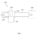
- FIG. 1 is a schematic diagram of an electrically-powered power steering device (100).
- This power steering device (100) is used for assisting the operation of a handle (a steering wheel) in a vehicle such as an automobile.
- the power steering device (100) has a torque sensor (102) which detects the power applied to the handle through an shaft part (101) connected to a steering apparatus (200), a control unit (103) which calculates the necessary assist power based on the output from the torque sensor (102), a motor (50) which generates the rotative force based on the output from the control unit (103), and a reduction mechanism (104) which reduces the rotative force of the motor (50) and delivers the same to the steering apparatus (200).
- a torque sensor (102) which detects the power applied to the handle through an shaft part (101) connected to a steering apparatus (200)
- a control unit (103) which calculates the necessary assist power based on the output from the torque sensor (102)
- a motor (50) which generates the rotative force based
- the motor (50) of the power steering device (100) is operated by the power applied to the handle, and the rotation of the handle is assisted by the rotative force of the motor (50), which makes it possible to operate the handle with a small amount of force.
- FIG. 2 is a schematic diagram of a section of the motor (50).
- the motor (50) is a so called inner-rotor type motor configured with 8 poles and 12 slots.
- the motor (50) comprises a shaft (51), a rotor (52), a stator (1), a bus bar unit (30), and a motor housing (5).
- the stator (1) approximately in a form of a cylinder is provided in the motor housing (5) as illustrated in FIG. 3 .
- the rotor (52) approximately in a form of a cylinder is fixed around the circumference of the shaft (51) which is rotably supported to the motor housing (5).
- the outer circumference surface of the rotor (52) and the inner circumference surface of the stator (1) are facing each other with a slight gap therebetween.
- 8 magnets (54,...,54) (8 poles) are arranged in even intervals around the outer circumference of the rotor (52) so that the N-pole and the S-pole are arranged alternately.
- the stator (1) comprises a core (2), an insulator (3), and a coil (4).
- the core (2) is formed by laminating sheets of steel.
- the core (2) has a ring part (21) in a form of a ring and a teeth part (22).
- the teeth part (22) consists of twelve elemental teeth parts (22a,...,22a) projecting from the inside of the ring part (21) toward the center thereof.
- a conductive line is winded around each elemental teeth part (22a) through the insulator (3), and the coil (4) is formed by so called concentrated winding. That is, a coil group consisting of twelve coils (4,...,4) is formed in the teeth part (22). Further, a conductive line is accommodated within the twelve spaces (slots) (6,...,6) between the adjacent elemental teeth parts (22a) (12 slots).
- the core (2) is formed by coupling the twelve elemental cores (2a,...,2a).
- Each elemental core (2a) is extended to the axial direction and has an external form with an approximately T-shaped section, and each elemental core has an elemental teeth part (22a) (see FIG. 5 ).
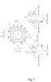
- a conductive line is winded to every two elemental teeth parts (22a) to form total six pairs of coils (40,...,40).
- a coil pair (40) connecting two coils (4,4) is formed by consecutively winding a conductive line to each elemental teeth part (22a,22a) with respect to unconnected two elemental cores (2a,2a).
- the winding direction of the two coils (4,4) in each coil pair (40) is arranged in the same direction when viewed from a front end side of the elemental teeth part (22a).
- the winding direction of the two coils (4,4) in each coil pair (40) is arranged in a clockwise direction; however, a counter clockwise direction is also applicable.
- the coil pair (40) consists of two types of coil pairs (40a,40b) where the winding directions of conductive line are different.
- the coil pair (40a) comprises a first coil pair - a third coil pair (41,42,43) where the winding of the two coils (4,4) starts from the left coil (4) and ends at the right coil (4).
- the coil pair (40b) comprises a fourth coil pair - a sixth coil pair (44,45,46) where the winding starts from the right coil (4) and ends at the left coil (4).
- the winding in the first coil pair - the third coil pair (41,42,43) respectively starts from their left coils (41b,42b,43b) and ends at the right coils (41a,42a,43a).
- the winding in the fourth coil pair - the sixth coil pair (44,45,46) starts from their right coils (44b,45b,46b) and ends at the left coils (44a,45a,46a).
- the white circle illustrates a starting end of winding
- the black circle illustrates a finishing end of winding.
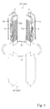
- the two types of coil pairs (40a,40b) where the winding directions of conductive line are different can be easily formed, for example, by using the method illustrated in FIG. 5 . That is, one coil pair [40a(40b)] can be formed by bending the coil pair (40) winded in the same direction as the other coil pair [40b(40a)] in an opposite direction at its jumper wire (47) portion and then changing the left and right of each elemental core (2a). Thus, it is desirable to form one coil pair [40a(40b)] first, and then form the other coil pair [40b(40a)] by bending the necessary portion of the coil pair [40a(40b)] for connecting each elemental core (2a), which provides excellent work efficiency.
- Each coil pair (40) is installed in a predetermined arrangement so that the motor efficiency is performed suitably for the power steering device (100).
- the core (2) when the core (2) is viewed in its axial direction and virtually divided by a first compartment line (23) into a first region (24) and a second region (25), the first coil pair - the third coil pair (41,42,43) are arranged in the first region (24), and the fourth coil pair - the sixth coil pair (44,45,46) is arranged in the second region (25).
- the coil (42a) of the second coil pair (42) and the coil (43a) of the third coil pair (43) are arranged to be placed between the two coils (41a,41b) of the first coil pair (41). That is, in the first region (24) [or the second region (25)], one coils (4) respectively from another two coil pairs (40) are arranged between the two coils (4,4) of one coil pair (40).
- each coil pair (40) is arranged in a symmetrical form with respect to the first compartment line (23) in the first region (24) and the second region (25).
- the coil (41a), the coil (42a), the coil (43a), the coil (41b), the coil (42b), the coil (43b) are arranged in a counter clockwise direction in said order.
- the coil (44a), the coil (45a), the coil (46a), the coil (44b), the coil (45b), the coil (46b) are arranged in a clockwise direction in said order.
- Such arrangement makes it possible to form a star connection which corresponds to the U-phase, V-phase, W-phase illustrated in FIG. 6 .
- the core (2) is divided by a second compartment line (26) perpendicular to the first compartment line (23) into a phase region and a neutral region equally along the axial direction, one coils (41a,...,46a) of the first coil pair - the sixth coil pair (41,...,46) are arranged in the phase region (27), and the other coils (41b,...,46b) are arranged in the neutral region (28).
- the conductive lines derived from the neutral region (28) can all be connected to a neutral point (N).
- the bus bar unit (30) consists of a plurality of bus bars (32) and a holder (31).
- the holder (31) is an injection molded article made by an insulating resin such as polybutylenetelephthalate (PBT) including fiber.
- the holder (31) comprises a bus bar supporting part (31a) in a form of a ring, a connector part (31b) formed integrally with the bus bar supporting part (31a), and a plurality of supporting leg parts (31c,...,31c) for attaching to the motor housing (5).
- the bus bar (32) is a press processed article of a metal plate with excellent conductivity, such as copper.
- Each bus bar (32) is formed integrally with the holder (31) by a method so called insert molding.
- the bus bar (32) of the present embodiment is extended to the circumferential direction in a strip form and comprises a first bus bar (32a) in an approximate semicircle, and a second bus bar - a fourth bus bar (32b,32c,32d) which is respectively in a form of a minor arc having different lengths.
- a plurality of connecting terminals (33,33,...) is formed to protrude from the outer circumference of each bus bar (32).
- the conductive line derived from the stator (1) is connected to these connecting terminals (33,33,).
- a second - fourth connector terminals (34b,34c,34d) standing approximately perpendicularly are formed integrally at the end of each of the second bus bar - the fourth bus bar (32b,32c,32d).
- the front end of the second - fourth connector terminals (34b,34c,34d) are protruded from the connector part (31b) of each holder (31).
- Each bus bar (32) is embedded in the bus bar supporting part (31a) so as not to contact with each other.
- the bus bar supporting part (31a) is divided into a phase side region (37) and a neutral side region (36) by a bisectrix (35) equally along the axial direction
- the first bus bar (32a) is arranged in the neutral side region (36)
- the second bus bar - the fourth bus bar (32b,32c,32d) are arranged in the phase side region (37).
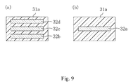
- the second bus bar - the fourth bus bar are arranged to overlap with each other with a resin layer therebetween.
- FIG. 9(b) only the first bus bar (32a) is arranged in the neutral side region (36).
- the bus bar unit (30) is connected to the stator (1). That is, the neutral side region (36) of the bus bar unit (30) is arranged correspondingly to the neutral region (28) of the stator (1), and the phase side region (37) of the bus bar unit (30) is arranged correspondingly to the phase region (27) of the stator (1). Further, the conductive line derived from the neutral region (28) of the stator (1), specifically, the conductive line derived from the coil (41b), the coil (42b), the coil (43b), the coil (44b), the coil (45b), the coil (46b) is connected to each of the connecting terminals (33,...,33) of the first bus bar (32a).
- the conductive line derived from the phase region (27) of the stator (1) is connected to certain connecting terminals (33,...,33) of the second bus bar - the fourth bus bar (32b,32c,32d).
- the conductive lines derived from the coil (43a) and the coil (44a) are connected to each of the connecting terminals (33,33) of the second bus bar (32b).
- the conductive lines derived from the coil (42a) and the coil (45a) are connected to each of the connecting terminals (33,33) of the third bus bar (32c).
- the conductive lines derived from the coil (41a) and the coil (46a) are connected to each of the connecting terminals (33,33) of the fourth bus bar (32d).
- a neutral point (N) is formed by the first bus bar (32a), and a star connection illustrated in FIG. 6 is formed by each of the contact points (U,V,W) which are formed by the second bus bar - the fourth bus bar (32b,32c,32d).
- FIG. 11 illustrates an example of a conventional bus bar unit.
- the bus bar for the neutral point is shaped in the forms of a ring or a major arc in order to prevent the conductive line from crawling about.
- the bus bar unit (30) of the present embodiment provides the first bus bar (32a) for the neutral point in a form of an approximate semicircle, and the second bus bar - the fourth bus bar (32b,32c,32d) for a contact points of each phase in a form of a minor arc and arranges them respectively in the neutral side region (36) and the phase side region (37) of the bus bar unit (30), which makes it possible to decrease the thickness of the bus bar supporting part and therefore enables the miniaturization of the bus bar unit (30).
- This also provides easy wire connection with the stator (1) and improves work efficiency.
Landscapes
- Engineering & Computer Science (AREA)
- Power Engineering (AREA)
- Chemical & Material Sciences (AREA)
- Combustion & Propulsion (AREA)
- Transportation (AREA)
- Mechanical Engineering (AREA)
- Windings For Motors And Generators (AREA)
- Insulation, Fastening Of Motor, Generator Windings (AREA)
- Power Steering Mechanism (AREA)
Abstract
Description
- The present invention relates to a stator, a bus bar unit, a motor, and a power steering device.
- The pole number (a rotor's magnetic pole number) or the slot number (which corresponds to magnetic pole number on the stator's side), which is a basic constitution of a motor, is appropriately decided in accordance with the motor's specifications. Usually, a coil arrangement is designed for each combination of said number of poles or said number of slots.
- For example, a 14 electrode-12 slot brushless motor which forms a rotating magnetic field by a three-phase coil group consisting of a U-phase, a V-phase and a W-phase is well known (Japanese Patent Application Publication No.
2006-50690 - Patent Document:
JP-A 2006-050690 - Such constitution of a bus bar unit is decided in accordance with the constitution of a stator or the specification of a motor; however, the smallest and simplest structure is desirable.
- The stator according to one embodiment of the present invention comprises a core and a coil group. The core has a ring part in a form of a ring, and a teeth part consisting of twelve elemental teeth parts. The coil group consists of twelve coils formed in each of the elemental teeth parts. The core is formed by coupling twelve elemental cores having an elemental teeth part. The coil group is constituted of six pairs of coils each consisting of two coils joined to each other by a single conductive line. When the core is divided into a phase region and a neutral region equally along the axial direction, one coils in the six pairs of coils are arranged in the phase region, and the other coils are arranged in the neutral region.
- Also, the bus bar unit according to one embodiment the present invention comprises a plurality of bus bars and an insulating holder where the plurality of bus bars is arranged. The holder has a bus bar supporting part in a form of a ring. The bus bar has a first bus bar approximately in a form of a semicircle and at least a second bus bar - a fourth bus bar in a form of a minor arc. When the bus bar supporting part is divided into a phase region and a neutral region equally along the axial direction, the first bus bar is arranged in the neutral region, and a least the second bus bar - the fourth bus bar are arranged in the phase region in an overlapping manner.
- The present invention makes it possible to provide a miniaturized motor or to reduce the expenses used in the materials.
-
-
FIG. 1 is a schematic diagram of the power steering device according to a desirable embodiment of the invention. -
FIG. 2 is a schematic sectional view of the motor's constitution according to a desirable embodiment of the invention. -
FIG. 3 is a schematic perspective view of the stator according to a desirable embodiment of the invention. -
FIG. 4 is a schematic diagram for illustrating the coil arrangement according to a desirable embodiment of the invention. -
FIG. 5 is a diagram for illustrating the coil pair according to a desirable embodiment of the invention. -
FIG. 6 is a wiring diagram of the stator according to a desirable embodiment of the invention. -
FIG. 7 is a schematic perspective view of the bus bar unit according to a desirable embodiment of the invention. -
FIG. 8 is a schematic perspective view of the bus bar according to a desirable embodiment of the invention. -
FIG. 9 is a portion of a sectional view ofFIG. 7 . (a) is a sectional view of the X-X line, (b) is a sectional view of the Y-Y line. -
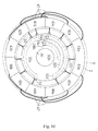
FIG. 10 is schematic diagram for illustrating the wire connection between the stator and the bus bar. -
FIG. 11 is a portion of a sectional view of a conventional bus bar unit. -
1: stator 2: core 2a: elemental core 4: coil 21: ring part 22: teeth part 22a: elemental teeth part 27: phase region 28: neutral region 40: coil pair - Set forth below are detailed descriptions of a desirable embodiment for the present invention based on the diagrams. The descriptions below are substantially examples, and they do not necessarily imply any limitations on the present invention, where it is applied to or how it is used.
-
FIG. 1 is a schematic diagram of an electrically-powered power steering device (100). This power steering device (100) is used for assisting the operation of a handle (a steering wheel) in a vehicle such as an automobile. The power steering device (100) has a torque sensor (102) which detects the power applied to the handle through an shaft part (101) connected to a steering apparatus (200), a control unit (103) which calculates the necessary assist power based on the output from the torque sensor (102), a motor (50) which generates the rotative force based on the output from the control unit (103), and a reduction mechanism (104) which reduces the rotative force of the motor (50) and delivers the same to the steering apparatus (200). - In a vehicle loaded with the power steering device (100), the motor (50) of the power steering device (100) is operated by the power applied to the handle, and the rotation of the handle is assisted by the rotative force of the motor (50), which makes it possible to operate the handle with a small amount of force.
-
FIG. 2 is a schematic diagram of a section of the motor (50). The motor (50) is a so called inner-rotor type motor configured with 8 poles and 12 slots. The motor (50) comprises a shaft (51), a rotor (52), a stator (1), a bus bar unit (30), and a motor housing (5). - Specifically, the stator (1) approximately in a form of a cylinder is provided in the motor housing (5) as illustrated in
FIG. 3 . The rotor (52) approximately in a form of a cylinder is fixed around the circumference of the shaft (51) which is rotably supported to the motor housing (5). The outer circumference surface of the rotor (52) and the inner circumference surface of the stator (1) are facing each other with a slight gap therebetween. 8 magnets (54,...,54) (8 poles) are arranged in even intervals around the outer circumference of the rotor (52) so that the N-pole and the S-pole are arranged alternately. - The stator (1) comprises a core (2), an insulator (3), and a coil (4). The core (2) is formed by laminating sheets of steel. The core (2) has a ring part (21) in a form of a ring and a teeth part (22). The teeth part (22) consists of twelve elemental teeth parts (22a,...,22a) projecting from the inside of the ring part (21) toward the center thereof. A conductive line is winded around each elemental teeth part (22a) through the insulator (3), and the coil (4) is formed by so called concentrated winding. That is, a coil group consisting of twelve coils (4,...,4) is formed in the teeth part (22). Further, a conductive line is accommodated within the twelve spaces (slots) (6,...,6) between the adjacent elemental teeth parts (22a) (12 slots).
- The core (2) is formed by coupling the twelve elemental cores (2a,...,2a). Each elemental core (2a) is extended to the axial direction and has an external form with an approximately T-shaped section, and each elemental core has an elemental teeth part (22a) (see
FIG. 5 ). A conductive line is winded to every two elemental teeth parts (22a) to form total six pairs of coils (40,...,40). Specifically, a coil pair (40) connecting two coils (4,4) is formed by consecutively winding a conductive line to each elemental teeth part (22a,22a) with respect to unconnected two elemental cores (2a,2a). - As illustrated in
FIG. 4 , the winding direction of the two coils (4,4) in each coil pair (40) is arranged in the same direction when viewed from a front end side of the elemental teeth part (22a). In the present embodiment, the winding direction of the two coils (4,4) in each coil pair (40) is arranged in a clockwise direction; however, a counter clockwise direction is also applicable. - The coil pair (40) consists of two types of coil pairs (40a,40b) where the winding directions of conductive line are different. As illustrated in the left side of
FIG. 4 , for example, the coil pair (40a) comprises a first coil pair - a third coil pair (41,42,43) where the winding of the two coils (4,4) starts from the left coil (4) and ends at the right coil (4). As also illustrated in the right side ofFIG. 4 , the coil pair (40b) comprises a fourth coil pair - a sixth coil pair (44,45,46) where the winding starts from the right coil (4) and ends at the left coil (4). - Specifically, the winding in the first coil pair - the third coil pair (41,42,43) respectively starts from their left coils (41b,42b,43b) and ends at the right coils (41a,42a,43a). The winding in the fourth coil pair - the sixth coil pair (44,45,46) starts from their right coils (44b,45b,46b) and ends at the left coils (44a,45a,46a). Further in
FIG. 4 , the white circle illustrates a starting end of winding, and the black circle illustrates a finishing end of winding. - The two types of coil pairs (40a,40b) where the winding directions of conductive line are different can be easily formed, for example, by using the method illustrated in
FIG. 5 . That is, one coil pair [40a(40b)] can be formed by bending the coil pair (40) winded in the same direction as the other coil pair [40b(40a)] in an opposite direction at its jumper wire (47) portion and then changing the left and right of each elemental core (2a). Thus, it is desirable to form one coil pair [40a(40b)] first, and then form the other coil pair [40b(40a)] by bending the necessary portion of the coil pair [40a(40b)] for connecting each elemental core (2a), which provides excellent work efficiency. Each coil pair (40) is installed in a predetermined arrangement so that the motor efficiency is performed suitably for the power steering device (100). - As illustrated in
FIG. 4 , for example, when the core (2) is viewed in its axial direction and virtually divided by a first compartment line (23) into a first region (24) and a second region (25), the first coil pair - the third coil pair (41,42,43) are arranged in the first region (24), and the fourth coil pair - the sixth coil pair (44,45,46) is arranged in the second region (25). - Also, for example, the coil (42a) of the second coil pair (42) and the coil (43a) of the third coil pair (43) are arranged to be placed between the two coils (41a,41b) of the first coil pair (41). That is, in the first region (24) [or the second region (25)], one coils (4) respectively from another two coil pairs (40) are arranged between the two coils (4,4) of one coil pair (40).
- Further, the winding direction of each coil pair (40) is arranged in a symmetrical form with respect to the first compartment line (23) in the first region (24) and the second region (25).
- Specifically, in the first region (24), the coil (41a), the coil (42a), the coil (43a), the coil (41b), the coil (42b), the coil (43b) are arranged in a counter clockwise direction in said order. In the second region (25), the coil (44a), the coil (45a), the coil (46a), the coil (44b), the coil (45b), the coil (46b) are arranged in a clockwise direction in said order.
- Such arrangement makes it possible to form a star connection which corresponds to the U-phase, V-phase, W-phase illustrated in
FIG. 6 . At this time, when the core (2) is divided by a second compartment line (26) perpendicular to the first compartment line (23) into a phase region and a neutral region equally along the axial direction, one coils (41a,...,46a) of the first coil pair - the sixth coil pair (41,...,46) are arranged in the phase region (27), and the other coils (41b,...,46b) are arranged in the neutral region (28). Accordingly, the conductive lines derived from the neutral region (28) can all be connected to a neutral point (N). - As it will be explained later, such arrangement makes it possible to simplify the wire connection between the stator (1) and the bus bar unit (30), and therefore provides excellent work efficiency. Further, it is also possible to miniaturize the bus bar unit (30) or the bus bar (32), and therefore reduce the expenses used in the materials.
- As illustrated in
FIG. 7 , the bus bar unit (30) consists of a plurality of bus bars (32) and a holder (31). The holder (31) is an injection molded article made by an insulating resin such as polybutylenetelephthalate (PBT) including fiber. The holder (31) comprises a bus bar supporting part (31a) in a form of a ring, a connector part (31b) formed integrally with the bus bar supporting part (31a), and a plurality of supporting leg parts (31c,...,31c) for attaching to the motor housing (5). - The bus bar (32) is a press processed article of a metal plate with excellent conductivity, such as copper. Each bus bar (32) is formed integrally with the holder (31) by a method so called insert molding. As illustrated in
FIG. 8 , the bus bar (32) of the present embodiment is extended to the circumferential direction in a strip form and comprises a first bus bar (32a) in an approximate semicircle, and a second bus bar - a fourth bus bar (32b,32c,32d) which is respectively in a form of a minor arc having different lengths. A plurality of connecting terminals (33,33,...) is formed to protrude from the outer circumference of each bus bar (32). The conductive line derived from the stator (1) is connected to these connecting terminals (33,33,...). A second - fourth connector terminals (34b,34c,34d) standing approximately perpendicularly are formed integrally at the end of each of the second bus bar - the fourth bus bar (32b,32c,32d). The front end of the second - fourth connector terminals (34b,34c,34d) are protruded from the connector part (31b) of each holder (31). - Each bus bar (32) is embedded in the bus bar supporting part (31a) so as not to contact with each other. Specifically, for example, when the bus bar supporting part (31a) is divided into a phase side region (37) and a neutral side region (36) by a bisectrix (35) equally along the axial direction, the first bus bar (32a) is arranged in the neutral side region (36) and the second bus bar - the fourth bus bar (32b,32c,32d) are arranged in the phase side region (37). As illustrated in
FIG. 9(a) , in the phase side region (37), the second bus bar - the fourth bus bar are arranged to overlap with each other with a resin layer therebetween. Meanwhile, as illustrated inFIG. 9(b) , only the first bus bar (32a) is arranged in the neutral side region (36). - As illustrated in
FIG. 10 , the bus bar unit (30) is connected to the stator (1). That is, the neutral side region (36) of the bus bar unit (30) is arranged correspondingly to the neutral region (28) of the stator (1), and the phase side region (37) of the bus bar unit (30) is arranged correspondingly to the phase region (27) of the stator (1). Further, the conductive line derived from the neutral region (28) of the stator (1), specifically, the conductive line derived from the coil (41b), the coil (42b), the coil (43b), the coil (44b), the coil (45b), the coil (46b) is connected to each of the connecting terminals (33,...,33) of the first bus bar (32a). - The conductive line derived from the phase region (27) of the stator (1) is connected to certain connecting terminals (33,...,33) of the second bus bar - the fourth bus bar (32b,32c,32d). Specifically, the conductive lines derived from the coil (43a) and the coil (44a) are connected to each of the connecting terminals (33,33) of the second bus bar (32b). The conductive lines derived from the coil (42a) and the coil (45a) are connected to each of the connecting terminals (33,33) of the third bus bar (32c). The conductive lines derived from the coil (41a) and the coil (46a) are connected to each of the connecting terminals (33,33) of the fourth bus bar (32d). With such arrangements, a neutral point (N) is formed by the first bus bar (32a), and a star connection illustrated in
FIG. 6 is formed by each of the contact points (U,V,W) which are formed by the second bus bar - the fourth bus bar (32b,32c,32d). -
FIG. 11 illustrates an example of a conventional bus bar unit. When the conductive line connected to the neutral point is spread out widely around the circumference of the stator, it is common for the bus bar for the neutral point is shaped in the forms of a ring or a major arc in order to prevent the conductive line from crawling about. - However, such arrangement makes the thickness of the bus bar supporting part (310a) thicker because the four bus bars (320a,320b,320c,320d) would be overlapped as shown in the bus bar unit illustrated in
FIG. 11 . Regarding such problem, the bus bar unit (30) of the present embodiment provides the first bus bar (32a) for the neutral point in a form of an approximate semicircle, and the second bus bar - the fourth bus bar (32b,32c,32d) for a contact points of each phase in a form of a minor arc and arranges them respectively in the neutral side region (36) and the phase side region (37) of the bus bar unit (30), which makes it possible to decrease the thickness of the bus bar supporting part and therefore enables the miniaturization of the bus bar unit (30). This also provides easy wire connection with the stator (1) and improves work efficiency.
Claims (10)
- A stator comprising: a ring part in a form of a ring; a core having a teeth part which consists of twelve elemental teeth parts projecting from the inside of the ring part toward the center thereof; and a coil group which consists of twelve coils formed in each of the elemental teeth part, wherein the core is formed by coupling the twelve elemental cores which respectively have one elemental teeth part; the coil group is constituted of six coil pairs consisting of two of the twelve coils joined to each other by a conductive line; and when the core is divided into a phase region and a neutral region equally along the axial direction, the one coil in each of the six coil pairs is arranged in the phase region, and the other coil is arranged in the neutral region.
- The stator according to Claim 1, wherein winding directions of the two coils in each of the coil pairs are arranged in the same direction viewed from a front end side of the elemental teeth part; the coil pairs comprise a first coil pair - a third coil pair where the winding of the coil pair starts from one coil and ends at the other coil, and a fourth coil pair - a sixth coil pair where the winding of the coil pair starts from the other coil and ends at the one coil; when the core is divided by a first compartment line equally along the axial direction into a first region and a second region, the first coil pair - the third coil pair are arranged in the first region, and the fourth coil pair - the sixth coil pair are arranged in the second region; and when the core is divided by a second compartment line perpendicular to the first compartment line equally along the axial direction into a phase region and a neutral region, one coil in each of the first coil pair - the sixth coil pair is arranged in the phase region, and the other coil is arranged in the neutral region.
- The stator according to Claim 1 or 2, wherein each of the coil pair is connected in a star connection; and all of the conductive lines derived from the neutral region are connected to a neutral point.
- A bus bar unit comprising a plurality of bus bars; and an insulating holder where the plurality of bus bars are arranged, wherein the holder has a bus bar supporting part in a form of a ring; the bus bar comprises a first bus bar in a form of an approximate semicircle and at least a second bus bar - a fourth bus bar in a form of a minor arc; and when the bus bar supporting part is viewed from its axial direction and is divided into phase side region and a neutral side region, the first bus bar is arranged in the neutral side region, and the at least second bus bar - the fourth bus bar are arranged in the phase side region to overlap with each other.
- The bus bar unit according to Claim 4, wherein the first bus bar is used for the star connection connected to a neutral point.
- A motor comprising the stator according to any one of Claims 1 to 3.
- The motor according to Claim 6, further comprising a rotor configured with 8 magnetic poles.
- A motor comprising the bus bar unit according to Claim 4 or 5.
- A motor comprising the stator according to Claim 3, further comprising the motor according to Claim 5.
- A power steering device comprising the motor according to any one of Claims 6 to 9.
Applications Claiming Priority (2)
| Application Number | Priority Date | Filing Date | Title |
|---|---|---|---|
| JP2009039159A JP2010200400A (en) | 2009-02-23 | 2009-02-23 | Stator, bus bar unit, motor, and power steering device |
| PCT/JP2010/052756 WO2010095752A1 (en) | 2009-02-23 | 2010-02-23 | Stator, bus bar unit, motor, and power steering device |
Publications (3)
| Publication Number | Publication Date |
|---|---|
| EP2400635A1 true EP2400635A1 (en) | 2011-12-28 |
| EP2400635A4 EP2400635A4 (en) | 2017-05-24 |
| EP2400635B1 EP2400635B1 (en) | 2019-01-09 |
Family
ID=42634027
Family Applications (1)
| Application Number | Title | Priority Date | Filing Date |
|---|---|---|---|
| EP10743875.6A Active EP2400635B1 (en) | 2009-02-23 | 2010-02-23 | Stator, bus bar unit, motor, and power steering device |
Country Status (6)
| Country | Link |
|---|---|
| US (1) | US8674578B2 (en) |
| EP (1) | EP2400635B1 (en) |
| JP (1) | JP2010200400A (en) |
| KR (1) | KR101213124B1 (en) |
| CN (1) | CN102326320B (en) |
| WO (1) | WO2010095752A1 (en) |
Cited By (2)
| Publication number | Priority date | Publication date | Assignee | Title |
|---|---|---|---|---|
| WO2020002847A1 (en) * | 2018-06-27 | 2020-01-02 | Avo Carbon France | Manufacture of a multiphase electric power distribution device |
| EP4057483A1 (en) * | 2021-03-09 | 2022-09-14 | Hyundai Mobis Co., Ltd. | Stator for motor and motor including the same |
Families Citing this family (42)
| Publication number | Priority date | Publication date | Assignee | Title |
|---|---|---|---|---|
| US8816550B2 (en) * | 2010-11-05 | 2014-08-26 | Lg Innotek Co., Ltd. | Bus bar and EPS motor having the same |
| JP5813463B2 (en) * | 2011-11-02 | 2015-11-17 | 株式会社東芝 | Rotating electric machine stator, stator holder, rotating electric machine, and automobile |
| JP5810869B2 (en) * | 2011-11-28 | 2015-11-11 | トヨタ自動車株式会社 | Rotating electrical machine terminal module and rotating electrical machine equipped with the same |
| JP5939006B2 (en) * | 2012-04-13 | 2016-06-22 | 株式会社ジェイテクト | Rotating electric machine |
| KR101992687B1 (en) * | 2012-06-28 | 2019-06-25 | 엘지이노텍 주식회사 | Motor |
| WO2014011809A1 (en) * | 2012-07-11 | 2014-01-16 | Remy Technologies, Llc | Buss bar assembly having axially stacked buss bar plates |
| JP6135982B2 (en) * | 2013-01-17 | 2017-05-31 | 日本電産株式会社 | motor |
| JP6053001B2 (en) * | 2013-03-08 | 2016-12-27 | Kyb株式会社 | Bus bar unit |
| JP5850264B2 (en) * | 2013-06-25 | 2016-02-03 | 株式会社デンソー | Rotating electric machine stator |
| US9143022B2 (en) * | 2013-07-29 | 2015-09-22 | General Electric Company | System and method for rebalancing generator rotor in-situ |
| FR3018964B1 (en) * | 2014-03-24 | 2016-03-04 | Valeo Equip Electr Moteur | INTERCONNECTION ELEMENT FOR CONNECTING STATOR COILS |
| JP6539997B2 (en) * | 2014-11-25 | 2019-07-10 | 日本電産株式会社 | motor |
| US10205365B2 (en) | 2016-03-30 | 2019-02-12 | Milwaukee Electric Tool Corporation | Brushless motor for a power tool |
| DE102016225170A1 (en) | 2016-12-15 | 2018-06-21 | Continental Automotive Gmbh | Guide ring for connection to a housing of an electrical machine |
| EP3573215A1 (en) * | 2017-01-18 | 2019-11-27 | Panasonic Intellectual Property Management Co., Ltd. | Molded coil body, method for producing same, motor, and method for assembling stator |
| JP2018117489A (en) * | 2017-01-20 | 2018-07-26 | 日本電産株式会社 | Rotor and motor using the same |
| JP2018117490A (en) * | 2017-01-20 | 2018-07-26 | 日本電産株式会社 | Rotor and motor using the same |
| JP6485486B2 (en) * | 2017-04-26 | 2019-03-20 | 日本電産株式会社 | Three-phase motor |
| JP6399144B2 (en) * | 2017-04-26 | 2018-10-03 | 日本電産株式会社 | motor |
| GB2563616B (en) | 2017-06-20 | 2021-03-10 | Dyson Technology Ltd | A stator assembly |
| DE102017211168A1 (en) * | 2017-06-30 | 2019-01-03 | Zf Friedrichshafen Ag | Stator interconnection device for a rotating electrical machine |
| KR101904287B1 (en) * | 2017-07-03 | 2018-10-04 | 효성전기주식회사 | Winding method of brushlees motor with simple bus-bar structure |
| KR101904312B1 (en) * | 2017-07-03 | 2018-10-04 | 효성전기주식회사 | Method for arranging bus-bar of brushlees motor |
| KR102489299B1 (en) | 2017-09-06 | 2023-01-17 | 엘지이노텍 주식회사 | Motor |
| KR20190095748A (en) * | 2018-02-07 | 2019-08-16 | 엘지이노텍 주식회사 | Motor |
| WO2020013078A1 (en) * | 2018-07-13 | 2020-01-16 | 日本電産株式会社 | Motor and electric power steering device |
| KR20200008835A (en) * | 2018-07-17 | 2020-01-29 | 현대자동차주식회사 | Coil wiring unit of drive motor for vehicle and fabrication method thereof |
| WO2020039961A1 (en) * | 2018-08-20 | 2020-02-27 | 日本電産株式会社 | Motor, electric power steering device, motor manufacturing method, bus bar unit, and bus bar unit manufacturing method |
| KR20200029876A (en) * | 2018-09-11 | 2020-03-19 | 엘지이노텍 주식회사 | Motor |
| CN114026770A (en) * | 2019-06-28 | 2022-02-08 | 日本电产株式会社 | Bus and motor |
| WO2021031783A1 (en) * | 2019-08-20 | 2021-02-25 | 安徽威灵汽车部件有限公司 | Busbar, busbar main body, motor, electric power steering system, and vehicle |
| KR102860217B1 (en) * | 2020-01-03 | 2025-09-16 | 엘지이노텍 주식회사 | Motor |
| WO2021247954A1 (en) | 2020-06-05 | 2021-12-09 | Milwaukee Electric Tool Corporation | Brushless motor for a power tool |
| CN112737182B (en) * | 2020-12-10 | 2022-06-14 | 宜兴华永电机有限公司 | Wire embedding method for improving utilization rate of stator slots of doubly-fed generator |
| JP7109610B1 (en) * | 2021-02-19 | 2022-07-29 | 三菱電機株式会社 | Rotating electric machine stator and its coil connecting device |
| JP7700661B2 (en) * | 2021-12-16 | 2025-07-01 | 株式会社豊田自動織機 | Rotating Electric Machine |
| US20250132625A1 (en) * | 2021-12-27 | 2025-04-24 | Nhk Spring Co., Ltd. | Stator |
| JP2023176648A (en) * | 2022-05-31 | 2023-12-13 | 株式会社デンソー | Stator assembly method and stator assembly device |
| CN117856499A (en) * | 2022-09-30 | 2024-04-09 | 日本电产株式会社 | Motor |
| WO2024216262A1 (en) | 2023-04-14 | 2024-10-17 | Garner Development Services, Llc | Caseless electric motor with a stationary shaft for marine enviroments |
| WO2024227054A1 (en) | 2023-04-27 | 2024-10-31 | Garner Development Services, Llc | Jet pump propulsion system |
| JP2025023736A (en) * | 2023-08-04 | 2025-02-17 | 株式会社ミツバ | Motor |
Family Cites Families (12)
| Publication number | Priority date | Publication date | Assignee | Title |
|---|---|---|---|---|
| JP3017085B2 (en) * | 1995-11-02 | 2000-03-06 | 三菱電機株式会社 | Rotating electric machine and method of manufacturing the same |
| JP3623683B2 (en) * | 1999-03-09 | 2005-02-23 | 山洋電気株式会社 | Manufacturing method of stator for rotating electrical machine and stator for rotating electrical machine |
| JP3735250B2 (en) | 2000-12-22 | 2006-01-18 | 株式会社ミツバ | Armature winding structure |
| EP1542339A4 (en) * | 2002-07-22 | 2008-07-02 | Nsk Ltd | Motor, method of manufacturing motor, and driving control device for motor |
| JP4112535B2 (en) | 2004-07-30 | 2008-07-02 | 株式会社一宮電機 | Stator and brushless motor |
| JP4662200B2 (en) * | 2004-09-29 | 2011-03-30 | 日本電産株式会社 | Motor and busbar |
| JP4916730B2 (en) * | 2006-02-07 | 2012-04-18 | アスモ株式会社 | Stator manufacturing method and stator |
| JP5217117B2 (en) * | 2006-06-05 | 2013-06-19 | 日本電産株式会社 | Brushless motor |
| JP4251196B2 (en) * | 2006-06-16 | 2009-04-08 | トヨタ自動車株式会社 | Motor for steering device |
| JP2008284912A (en) * | 2007-05-15 | 2008-11-27 | Jtekt Corp | Vehicle steering system |
| JP2009027777A (en) * | 2007-07-17 | 2009-02-05 | Jtekt Corp | Permanent magnet type brushless motor |
| US7893587B2 (en) * | 2008-10-23 | 2011-02-22 | Electromag Sa | Brushless DC electric motor |
-
2009
- 2009-02-23 JP JP2009039159A patent/JP2010200400A/en active Pending
-
2010
- 2010-02-23 EP EP10743875.6A patent/EP2400635B1/en active Active
- 2010-02-23 WO PCT/JP2010/052756 patent/WO2010095752A1/en not_active Ceased
- 2010-02-23 KR KR1020117008585A patent/KR101213124B1/en active Active
- 2010-02-23 US US13/202,631 patent/US8674578B2/en active Active
- 2010-02-23 CN CN201080008915.7A patent/CN102326320B/en active Active
Non-Patent Citations (1)
| Title |
|---|
| See references of WO2010095752A1 * |
Cited By (4)
| Publication number | Priority date | Publication date | Assignee | Title |
|---|---|---|---|---|
| WO2020002847A1 (en) * | 2018-06-27 | 2020-01-02 | Avo Carbon France | Manufacture of a multiphase electric power distribution device |
| FR3083387A1 (en) * | 2018-06-27 | 2020-01-03 | Avo Carbon France | MANUFACTURE OF A MULTI-PHASE ELECTRIC POWER DISTRIBUTION DEVICE |
| EP4057483A1 (en) * | 2021-03-09 | 2022-09-14 | Hyundai Mobis Co., Ltd. | Stator for motor and motor including the same |
| US12184141B2 (en) | 2021-03-09 | 2024-12-31 | Hyundai Mobis Co., Ltd. | Stator for motor and motor including the same |
Also Published As
| Publication number | Publication date |
|---|---|
| EP2400635B1 (en) | 2019-01-09 |
| WO2010095752A1 (en) | 2010-08-26 |
| US8674578B2 (en) | 2014-03-18 |
| US20110297474A1 (en) | 2011-12-08 |
| CN102326320A (en) | 2012-01-18 |
| JP2010200400A (en) | 2010-09-09 |
| KR101213124B1 (en) | 2012-12-20 |
| CN102326320B (en) | 2014-06-25 |
| KR20110069088A (en) | 2011-06-22 |
| EP2400635A4 (en) | 2017-05-24 |
Similar Documents
| Publication | Publication Date | Title |
|---|---|---|
| EP2400635B1 (en) | Stator, bus bar unit, motor, and power steering device | |
| US9079603B2 (en) | Motor for an electric power steering apparatus | |
| CN106410995B (en) | Stator for rotating electric machine | |
| US10211699B2 (en) | Motor and bus bar unit having overlapping bridge portions | |
| JP6267907B2 (en) | Busbar unit and brushless motor | |
| CN101527486B (en) | Brushless motor | |
| US9397541B2 (en) | Stator for electric rotating machine and method of manufacturing the same | |
| EP2273654A2 (en) | Rotating electric machine and manufacturing method thereof | |
| US8896189B2 (en) | Stator for electric rotating machine and method of manufacturing the same | |
| US7825561B2 (en) | Motor with simplified structure and related control device | |
| EP2928048A1 (en) | Electric motor | |
| EP3200318A1 (en) | Brushless motor | |
| CN103973006B (en) | Rotor, stator and motor | |
| JP2005287240A (en) | Synchronous motor | |
| CN103107625A (en) | Rotary electric machine and method for manufacturing a stator coil connecting unit | |
| EP3032717A1 (en) | Brushless motor | |
| EP2445088A2 (en) | Brushless motor and electric power steering system | |
| CN112673555B (en) | motor | |
| CN111699616B (en) | Motor | |
| JP2014007939A (en) | Brushless motor | |
| CN103715788B (en) | The stator of electric motor and electric motor | |
| US20190131840A1 (en) | Rotary Electric Machine | |
| WO2021064883A1 (en) | Rotating electric machine | |
| JP5787005B2 (en) | Motor and power steering device | |
| JP4726526B2 (en) | Brushless motor |
Legal Events
| Date | Code | Title | Description |
|---|---|---|---|
| PUAI | Public reference made under article 153(3) epc to a published international application that has entered the european phase |
Free format text: ORIGINAL CODE: 0009012 |
|
| 17P | Request for examination filed |
Effective date: 20110803 |
|
| AK | Designated contracting states |
Kind code of ref document: A1 Designated state(s): AT BE BG CH CY CZ DE DK EE ES FI FR GB GR HR HU IE IS IT LI LT LU LV MC MK MT NL NO PL PT RO SE SI SK SM TR |
|
| DAX | Request for extension of the european patent (deleted) | ||
| RA4 | Supplementary search report drawn up and despatched (corrected) |
Effective date: 20170424 |
|
| RIC1 | Information provided on ipc code assigned before grant |
Ipc: H02K 3/52 20060101ALI20170418BHEP Ipc: H02K 3/28 20060101ALI20170418BHEP Ipc: H02K 3/18 20060101ALN20170418BHEP Ipc: B62D 5/04 20060101AFI20170418BHEP |
|
| STAA | Information on the status of an ep patent application or granted ep patent |
Free format text: STATUS: EXAMINATION IS IN PROGRESS |
|
| 17Q | First examination report despatched |
Effective date: 20180202 |
|
| REG | Reference to a national code |
Ref country code: DE Ref legal event code: R079 Ref document number: 602010056419 Country of ref document: DE Free format text: PREVIOUS MAIN CLASS: H02K0003180000 Ipc: B62D0005040000 |
|
| GRAP | Despatch of communication of intention to grant a patent |
Free format text: ORIGINAL CODE: EPIDOSNIGR1 |
|
| STAA | Information on the status of an ep patent application or granted ep patent |
Free format text: STATUS: GRANT OF PATENT IS INTENDED |
|
| RIC1 | Information provided on ipc code assigned before grant |
Ipc: B62D 5/04 20060101AFI20180629BHEP Ipc: H02K 3/28 20060101ALI20180629BHEP Ipc: H02K 3/52 20060101ALI20180629BHEP Ipc: H02K 3/18 20060101ALN20180629BHEP |
|
| INTG | Intention to grant announced |
Effective date: 20180720 |
|
| GRAS | Grant fee paid |
Free format text: ORIGINAL CODE: EPIDOSNIGR3 |
|
| GRAA | (expected) grant |
Free format text: ORIGINAL CODE: 0009210 |
|
| STAA | Information on the status of an ep patent application or granted ep patent |
Free format text: STATUS: THE PATENT HAS BEEN GRANTED |
|
| AK | Designated contracting states |
Kind code of ref document: B1 Designated state(s): AT BE BG CH CY CZ DE DK EE ES FI FR GB GR HR HU IE IS IT LI LT LU LV MC MK MT NL NO PL PT RO SE SI SK SM TR |
|
| REG | Reference to a national code |
Ref country code: GB Ref legal event code: FG4D |
|
| REG | Reference to a national code |
Ref country code: CH Ref legal event code: EP Ref country code: AT Ref legal event code: REF Ref document number: 1086913 Country of ref document: AT Kind code of ref document: T Effective date: 20190115 |
|
| REG | Reference to a national code |
Ref country code: DE Ref legal event code: R096 Ref document number: 602010056419 Country of ref document: DE |
|
| REG | Reference to a national code |
Ref country code: IE Ref legal event code: FG4D |
|
| REG | Reference to a national code |
Ref country code: NL Ref legal event code: MP Effective date: 20190109 |
|
| REG | Reference to a national code |
Ref country code: LT Ref legal event code: MG4D |
|
| PG25 | Lapsed in a contracting state [announced via postgrant information from national office to epo] |
Ref country code: NL Free format text: LAPSE BECAUSE OF FAILURE TO SUBMIT A TRANSLATION OF THE DESCRIPTION OR TO PAY THE FEE WITHIN THE PRESCRIBED TIME-LIMIT Effective date: 20190109 |
|
| REG | Reference to a national code |
Ref country code: AT Ref legal event code: MK05 Ref document number: 1086913 Country of ref document: AT Kind code of ref document: T Effective date: 20190109 |
|
| PG25 | Lapsed in a contracting state [announced via postgrant information from national office to epo] |
Ref country code: ES Free format text: LAPSE BECAUSE OF FAILURE TO SUBMIT A TRANSLATION OF THE DESCRIPTION OR TO PAY THE FEE WITHIN THE PRESCRIBED TIME-LIMIT Effective date: 20190109 Ref country code: PT Free format text: LAPSE BECAUSE OF FAILURE TO SUBMIT A TRANSLATION OF THE DESCRIPTION OR TO PAY THE FEE WITHIN THE PRESCRIBED TIME-LIMIT Effective date: 20190509 Ref country code: SE Free format text: LAPSE BECAUSE OF FAILURE TO SUBMIT A TRANSLATION OF THE DESCRIPTION OR TO PAY THE FEE WITHIN THE PRESCRIBED TIME-LIMIT Effective date: 20190109 Ref country code: PL Free format text: LAPSE BECAUSE OF FAILURE TO SUBMIT A TRANSLATION OF THE DESCRIPTION OR TO PAY THE FEE WITHIN THE PRESCRIBED TIME-LIMIT Effective date: 20190109 Ref country code: LT Free format text: LAPSE BECAUSE OF FAILURE TO SUBMIT A TRANSLATION OF THE DESCRIPTION OR TO PAY THE FEE WITHIN THE PRESCRIBED TIME-LIMIT Effective date: 20190109 Ref country code: FI Free format text: LAPSE BECAUSE OF FAILURE TO SUBMIT A TRANSLATION OF THE DESCRIPTION OR TO PAY THE FEE WITHIN THE PRESCRIBED TIME-LIMIT Effective date: 20190109 Ref country code: NO Free format text: LAPSE BECAUSE OF FAILURE TO SUBMIT A TRANSLATION OF THE DESCRIPTION OR TO PAY THE FEE WITHIN THE PRESCRIBED TIME-LIMIT Effective date: 20190409 |
|
| PG25 | Lapsed in a contracting state [announced via postgrant information from national office to epo] |
Ref country code: BG Free format text: LAPSE BECAUSE OF FAILURE TO SUBMIT A TRANSLATION OF THE DESCRIPTION OR TO PAY THE FEE WITHIN THE PRESCRIBED TIME-LIMIT Effective date: 20190409 Ref country code: IS Free format text: LAPSE BECAUSE OF FAILURE TO SUBMIT A TRANSLATION OF THE DESCRIPTION OR TO PAY THE FEE WITHIN THE PRESCRIBED TIME-LIMIT Effective date: 20190509 Ref country code: GR Free format text: LAPSE BECAUSE OF FAILURE TO SUBMIT A TRANSLATION OF THE DESCRIPTION OR TO PAY THE FEE WITHIN THE PRESCRIBED TIME-LIMIT Effective date: 20190410 Ref country code: LV Free format text: LAPSE BECAUSE OF FAILURE TO SUBMIT A TRANSLATION OF THE DESCRIPTION OR TO PAY THE FEE WITHIN THE PRESCRIBED TIME-LIMIT Effective date: 20190109 Ref country code: HR Free format text: LAPSE BECAUSE OF FAILURE TO SUBMIT A TRANSLATION OF THE DESCRIPTION OR TO PAY THE FEE WITHIN THE PRESCRIBED TIME-LIMIT Effective date: 20190109 |
|
| REG | Reference to a national code |
Ref country code: CH Ref legal event code: PL |
|
| REG | Reference to a national code |
Ref country code: DE Ref legal event code: R097 Ref document number: 602010056419 Country of ref document: DE |
|
| PG25 | Lapsed in a contracting state [announced via postgrant information from national office to epo] |
Ref country code: CZ Free format text: LAPSE BECAUSE OF FAILURE TO SUBMIT A TRANSLATION OF THE DESCRIPTION OR TO PAY THE FEE WITHIN THE PRESCRIBED TIME-LIMIT Effective date: 20190109 Ref country code: RO Free format text: LAPSE BECAUSE OF FAILURE TO SUBMIT A TRANSLATION OF THE DESCRIPTION OR TO PAY THE FEE WITHIN THE PRESCRIBED TIME-LIMIT Effective date: 20190109 Ref country code: IT Free format text: LAPSE BECAUSE OF FAILURE TO SUBMIT A TRANSLATION OF THE DESCRIPTION OR TO PAY THE FEE WITHIN THE PRESCRIBED TIME-LIMIT Effective date: 20190109 Ref country code: SK Free format text: LAPSE BECAUSE OF FAILURE TO SUBMIT A TRANSLATION OF THE DESCRIPTION OR TO PAY THE FEE WITHIN THE PRESCRIBED TIME-LIMIT Effective date: 20190109 Ref country code: MC Free format text: LAPSE BECAUSE OF FAILURE TO SUBMIT A TRANSLATION OF THE DESCRIPTION OR TO PAY THE FEE WITHIN THE PRESCRIBED TIME-LIMIT Effective date: 20190109 Ref country code: AT Free format text: LAPSE BECAUSE OF FAILURE TO SUBMIT A TRANSLATION OF THE DESCRIPTION OR TO PAY THE FEE WITHIN THE PRESCRIBED TIME-LIMIT Effective date: 20190109 Ref country code: DK Free format text: LAPSE BECAUSE OF FAILURE TO SUBMIT A TRANSLATION OF THE DESCRIPTION OR TO PAY THE FEE WITHIN THE PRESCRIBED TIME-LIMIT Effective date: 20190109 Ref country code: EE Free format text: LAPSE BECAUSE OF FAILURE TO SUBMIT A TRANSLATION OF THE DESCRIPTION OR TO PAY THE FEE WITHIN THE PRESCRIBED TIME-LIMIT Effective date: 20190109 Ref country code: LU Free format text: LAPSE BECAUSE OF NON-PAYMENT OF DUE FEES Effective date: 20190223 |
|
| PLBE | No opposition filed within time limit |
Free format text: ORIGINAL CODE: 0009261 |
|
| STAA | Information on the status of an ep patent application or granted ep patent |
Free format text: STATUS: NO OPPOSITION FILED WITHIN TIME LIMIT |
|
| REG | Reference to a national code |
Ref country code: BE Ref legal event code: MM Effective date: 20190228 |
|
| REG | Reference to a national code |
Ref country code: IE Ref legal event code: MM4A |
|
| PG25 | Lapsed in a contracting state [announced via postgrant information from national office to epo] |
Ref country code: SM Free format text: LAPSE BECAUSE OF FAILURE TO SUBMIT A TRANSLATION OF THE DESCRIPTION OR TO PAY THE FEE WITHIN THE PRESCRIBED TIME-LIMIT Effective date: 20190109 |
|
| 26N | No opposition filed |
Effective date: 20191010 |
|
| GBPC | Gb: european patent ceased through non-payment of renewal fee |
Effective date: 20190409 |
|
| PG25 | Lapsed in a contracting state [announced via postgrant information from national office to epo] |
Ref country code: CH Free format text: LAPSE BECAUSE OF NON-PAYMENT OF DUE FEES Effective date: 20190228 Ref country code: LI Free format text: LAPSE BECAUSE OF NON-PAYMENT OF DUE FEES Effective date: 20190228 |
|
| PG25 | Lapsed in a contracting state [announced via postgrant information from national office to epo] |
Ref country code: GB Free format text: LAPSE BECAUSE OF NON-PAYMENT OF DUE FEES Effective date: 20190409 Ref country code: IE Free format text: LAPSE BECAUSE OF NON-PAYMENT OF DUE FEES Effective date: 20190223 |
|
| PG25 | Lapsed in a contracting state [announced via postgrant information from national office to epo] |
Ref country code: SI Free format text: LAPSE BECAUSE OF FAILURE TO SUBMIT A TRANSLATION OF THE DESCRIPTION OR TO PAY THE FEE WITHIN THE PRESCRIBED TIME-LIMIT Effective date: 20190109 Ref country code: BE Free format text: LAPSE BECAUSE OF NON-PAYMENT OF DUE FEES Effective date: 20190228 Ref country code: FR Free format text: LAPSE BECAUSE OF NON-PAYMENT OF DUE FEES Effective date: 20190309 |
|
| PG25 | Lapsed in a contracting state [announced via postgrant information from national office to epo] |
Ref country code: TR Free format text: LAPSE BECAUSE OF FAILURE TO SUBMIT A TRANSLATION OF THE DESCRIPTION OR TO PAY THE FEE WITHIN THE PRESCRIBED TIME-LIMIT Effective date: 20190109 |
|
| PG25 | Lapsed in a contracting state [announced via postgrant information from national office to epo] |
Ref country code: MT Free format text: LAPSE BECAUSE OF NON-PAYMENT OF DUE FEES Effective date: 20190223 |
|
| PG25 | Lapsed in a contracting state [announced via postgrant information from national office to epo] |
Ref country code: CY Free format text: LAPSE BECAUSE OF FAILURE TO SUBMIT A TRANSLATION OF THE DESCRIPTION OR TO PAY THE FEE WITHIN THE PRESCRIBED TIME-LIMIT Effective date: 20190109 |
|
| PG25 | Lapsed in a contracting state [announced via postgrant information from national office to epo] |
Ref country code: HU Free format text: LAPSE BECAUSE OF FAILURE TO SUBMIT A TRANSLATION OF THE DESCRIPTION OR TO PAY THE FEE WITHIN THE PRESCRIBED TIME-LIMIT; INVALID AB INITIO Effective date: 20100223 |
|
| PG25 | Lapsed in a contracting state [announced via postgrant information from national office to epo] |
Ref country code: MK Free format text: LAPSE BECAUSE OF FAILURE TO SUBMIT A TRANSLATION OF THE DESCRIPTION OR TO PAY THE FEE WITHIN THE PRESCRIBED TIME-LIMIT Effective date: 20190109 |
|
| P01 | Opt-out of the competence of the unified patent court (upc) registered |
Effective date: 20230519 |
|
| PGFP | Annual fee paid to national office [announced via postgrant information from national office to epo] |
Ref country code: DE Payment date: 20260217 Year of fee payment: 17 |