EP2400328A1 - Apparatus for handling data conductors - Google Patents
Apparatus for handling data conductors Download PDFInfo
- Publication number
- EP2400328A1 EP2400328A1 EP11170540A EP11170540A EP2400328A1 EP 2400328 A1 EP2400328 A1 EP 2400328A1 EP 11170540 A EP11170540 A EP 11170540A EP 11170540 A EP11170540 A EP 11170540A EP 2400328 A1 EP2400328 A1 EP 2400328A1
- Authority
- EP
- European Patent Office
- Prior art keywords
- side wall
- subsection
- housing
- data conductors
- broken out
- Prior art date
- Legal status (The legal status is an assumption and is not a legal conclusion. Google has not performed a legal analysis and makes no representation as to the accuracy of the status listed.)
- Ceased
Links
- 239000004020 conductor Substances 0.000 title claims abstract description 47
- 230000003287 optical effect Effects 0.000 claims abstract description 16
- 230000000712 assembly Effects 0.000 claims abstract description 5
- 238000000429 assembly Methods 0.000 claims abstract description 5
- RYGMFSIKBFXOCR-UHFFFAOYSA-N Copper Chemical compound [Cu] RYGMFSIKBFXOCR-UHFFFAOYSA-N 0.000 description 1
- 229910052802 copper Inorganic materials 0.000 description 1
- 239000010949 copper Substances 0.000 description 1
- 230000001419 dependent effect Effects 0.000 description 1
- 238000011161 development Methods 0.000 description 1
- 230000018109 developmental process Effects 0.000 description 1
- 239000002184 metal Substances 0.000 description 1
- 229910052751 metal Inorganic materials 0.000 description 1
- 238000000034 method Methods 0.000 description 1
- 238000012856 packing Methods 0.000 description 1
Images


Classifications
-
- G—PHYSICS
- G02—OPTICS
- G02B—OPTICAL ELEMENTS, SYSTEMS OR APPARATUS
- G02B6/00—Light guides; Structural details of arrangements comprising light guides and other optical elements, e.g. couplings
- G02B6/46—Processes or apparatus adapted for installing or repairing optical fibres or optical cables
- G02B6/47—Installation in buildings
- G02B6/475—Mechanical aspects of installing cables in ducts or the like for buildings
-
- G—PHYSICS
- G02—OPTICS
- G02B—OPTICAL ELEMENTS, SYSTEMS OR APPARATUS
- G02B6/00—Light guides; Structural details of arrangements comprising light guides and other optical elements, e.g. couplings
- G02B6/44—Mechanical structures for providing tensile strength and external protection for fibres, e.g. optical transmission cables
- G02B6/4439—Auxiliary devices
- G02B6/444—Systems or boxes with surplus lengths
- G02B6/4441—Boxes
-
- G—PHYSICS
- G02—OPTICS
- G02B—OPTICAL ELEMENTS, SYSTEMS OR APPARATUS
- G02B6/00—Light guides; Structural details of arrangements comprising light guides and other optical elements, e.g. couplings
- G02B6/44—Mechanical structures for providing tensile strength and external protection for fibres, e.g. optical transmission cables
- G02B6/4439—Auxiliary devices
- G02B6/444—Systems or boxes with surplus lengths
- G02B6/44528—Patch-cords; Connector arrangements in the system or in the box
Definitions
- the present invention relates to an apparatus for handling data conductors, in particular optical waveguides, and junction points between data conductors, in particular between optical waveguides, according to the preamble of Claim 1.
- apparatuses for handling optical waveguides and junction points between optical waveguides are required to ensure structured wiring.
- One requirement made of such apparatuses is maximum population of said apparatuses together with a high packing density and simultaneous, low mechanical loading on the optical waveguides. Similar requirements are also made in the case of designing networks comprising copper conductors or other data conductors.
- the present invention is based on the problem of providing a novel apparatus for handling data conductors and junction points between data conductors.
- At least one opening by means of which data conductors can be inserted into the interior space and guided out of the said interior space, is defined on at least one side wall of the housing by a section of the side wall which can be broken out of the side wall, specifically in such a way that, in order to provide a relatively small opening, a first, inner subsection with a relatively small outer contour can be broken out of the side wall, and that, in order to provide a relatively large opening, a second, outer subsection with a relatively large outer contour can additionally be broken out of the side wall.
- At least one opening in at least one side wall of the housing of the apparatus according to the invention for handling data conductors is defined by a section which can be broken out of the side wall, with this section which can be broken out of the side wall comprising a first, inner subsection with a relatively small outer contour, and a second, outer subsection with a relatively large outer contour. It is possible to either break only the first, inner subsection with the relatively small outer contour out of the side wall or to break the first, inner subsection together with the second, outer subsection out of the side wall, in order to thus form a relatively small opening in the side wall in the first case and to form a relatively large opening in the side wall in the second case.
- the openings of different sizes are matched to different intended applications and uses.
- the relatively small openings serve to insert data conductors and to guide data conductors out by means of data cables
- the relatively large openings serve to accommodate plug-type connectors between data cables and therefore to insert data conductors by means of plug-type connectors and to guide data conductors out by means of plug-type connectors.
- the present invention relates to an apparatus for handling data conductors, in particular for handling optical waveguides, and for handling junction points between data conductors, in particular for handling junction points between optical waveguides.
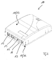
- FIG. 1 The invention will be described in greater detail below with reference to Figs 1 to 3 , with Figs 1 to 3 showing different views of an apparatus 10, which is in the form of a wall-mounted distribution device, for handling data conductors and junction points between data conductors.
- An apparatus 10 for handling data conductors and junction points between data conductors comprises a housing 11, with the housing 11 being formed, in the exemplary embodiment of Figs 1 and 2 , by a first housing part 12 and a second housing part 13.
- the first housing part 12 and the second housing part 13 of the housing 11 together define an interior space of the apparatus 10, with assemblies for connecting and/or laying data conductors being positioned in the interior space.
- the first housing part 12 is also without limitation to its orientation called housing lower part 12 and the second housing part 13 is also without limitation to its orientation called housing upper part 13.
- these assemblies may be, for example, splice cassettes and excess-length storage means.
- Data conductors are inserted into the interior space which is defined by the housing 11 and routed out of the said interior space by means of at least one side wall of the housing 11, specifically by means of at least one side wall 14 of the housing lower part 12 in the shown exemplary embodiment of Figs 1 to 4 , and to be precise by means of openings 15 made in the respective side wall 14.
- Figs 1 to 4 show a side wall 14 of the housing lower part 12, in which side wall four such openings 15 are made.
- the housing 11 can comprise further such openings, for example on a side wall which is situated opposite the side wall 14 of the housing lower part 12.
- two openings 15 in the side wall 14 of the housing lower part 12 of the housing 11 of the apparatus 10 according to the invention serve to insert data conductors into the housing 11 or the interior space, which is defined by the housing 11, by means of cables 16, with the data conductors being guided in the cables 16.
- these openings 15 are the two left-hand openings.
- the two right-hand openings 15 in the side wall 14 of the housing lower part 12 of the housing 11 of the apparatus 10 according to the invention serve, in contrast, to accommodate plug-type connectors 17 in order to thus insert data conductors, which are guided in data cables, into the apparatus 10 and to guide the said data conductors out of the said apparatus by means of the plug-type connectors 17 so as to form junction points in the region of the side wall 14.
- At least one opening 15 in at least one side wall 14 of the housing 11 of the apparatus 10 according to the invention is defined by a section 18 of the side wall 14 which can be broken out of the side wall 14, specifically by a first, inner subsection 19 and a second, outer subsection 20.
- the first, inner subsection 19 has a relatively small outer contour, it being possible to break the first, inner subsection 19 out of the respective side wall 14 in order to provide a relatively small opening 15.
- the second, outer subsection 20 of the section 18 has a relatively large outer contour, it being possible to break the second, outer subsection 20 and the first, inner subsection 19 out of the side wall 14 of the housing 11 in order to provide a relatively large opening 15.
- the two left-hand openings 15 are provided by in each case only the inner subsections 19 of the respective sections 18 being broken out of the side wall 14 of the housing lower part 12 of the housing 11. These openings 15 with relatively small dimensions serve, as already mentioned, to guide the data cables 16.
- the two subsections 19, 20 of the respective sections 18 are broken out of the side wall 14 of the housing lower part 12 of the housing 11, with, as already mentioned, the relatively large openings 15 serving to accommodate and handle the plug-type connectors 17.
- the second, outer subsection 20 of each section 18 which can be broken out of the side wall 14 externally surrounds at least sections of the first, inner subsection 19 of the said section in the state in which the subsections are not broken out of the side wall 14, specifically on three sides according to Fig. 3 .
- the second, outer subsection 20 is connected both to the first inner subsection 19 and to the side wall 14 by means of predetermined breaking points 21, 22 in the region of each section 18.
- the predetermined breaking points 21 are formed between the first, inner subsection 19 and the second, outer subsection 20 of the respective section 18 which can be broken out of the side wall 14 of the housing 11.
- the predetermined breaking points 22 run between the side wall 14 and the second, outer subsection 20 of the respective section 18 which can be broken out of the side wall 14.
- the first, inner subsection 19 of the section 18 is in each case broken out of the side wall 14 by breaking the predetermined breaking points 21 out of the side wall 14, while the second, outer subsection 20 is or remains connected to the side wall 14.
- the respective second, outer section 20 accordingly remains connected to the side wall 14 by means of the predetermined breaking points 22, whereas the predetermined breaking points 21 between the first, inner subsection 19 and the second, outer subsection 20 are broken.
- both the first, inner subsection 19 and the second, outer subsection 20 are broken out of the side wall 14 in the region of each opening 15.
- the predetermined breaking points 22 between the respective, second outer subsection 20 of the section 18 of the side wall 14 are accordingly broken.
- the respective side wall 14 from which the subsections 19, 20 of the sections 18 can be broken is preferably produced from a plastic.
- the entire housing 11 of the apparatus 10 according to the invention is typically produced from plastic, that is to say both the housing lower part 12 and the housing upper part 13. It is also possible to produce only the housing lower part 12 from plastic and to form the housing upper part 13 from metal. In particular, those housing parts which have at least one section 18 which can be broken out of the side wall in the region of at least one side wall are produced from plastic.
- the predetermined breaking points 21, 22 can be formed by a continuously uniform reduction in the wall thickness of the side wall 14 or by a section-by-section reduction in the wall thickness of the side wall 14 in the region of or along the predetermined breaking points 21, 22.
Landscapes
- Physics & Mathematics (AREA)
- General Physics & Mathematics (AREA)
- Optics & Photonics (AREA)
- Engineering & Computer Science (AREA)
- Civil Engineering (AREA)
- Structural Engineering (AREA)
- Light Guides In General And Applications Therefor (AREA)
- Mechanical Coupling Of Light Guides (AREA)
Abstract
Apparatus for handling data conductors, in particular optical waveguides, and junction points between data conductors, in particular between optical waveguides, having a housing (11) and having assemblies, which are accommodated in the housing (11), for connecting and/or laying data conductors, it being possible to insert data conductors in an interior space, which is defined by the housing, and to guide data conductors out of the said interior space by means of at least one side wall (14) of the housing, specifically by means of openings (15) made in the side wall, whereby at least one opening (15), by means of which data conductors can be inserted into the interior space and guided out of the said interior space, is defined on at least one side wall (14) of the housing (11) by a section (18) of the side wall which can be broken out of the side wall (14), specifically in such a way that, in order to provide a relatively small opening, a first, inner subsection (19) with a relatively small outer contour can be broken out of the side wall (14), and in that, in order to provide a relatively large opening, a second, outer subsection (20) with a relatively large outer contour can additionally be broken out of the side wall (14).
Description
- The present invention relates to an apparatus for handling data conductors, in particular optical waveguides, and junction points between data conductors, in particular between optical waveguides, according to the preamble of Claim 1.
- When designing, for example, optical waveguide cable networks, apparatuses for handling optical waveguides and junction points between optical waveguides are required to ensure structured wiring. One requirement made of such apparatuses is maximum population of said apparatuses together with a high packing density and simultaneous, low mechanical loading on the optical waveguides. Similar requirements are also made in the case of designing networks comprising copper conductors or other data conductors.
- The product catalogue "Zubehör für LWL-Kabelnetze [Accessories for optical waveguide cable networks], pages 182-187, edition 1, Corning Cable Systems GmbH & Co KG, year 2001" has already disclosed an apparatus, which is in the form of a wall-mounted distribution device, for handling optical waveguides and junction points between optical waveguides, the said apparatus comprising a housing and assemblies, which are accommodated in the housing, for connecting and/or laying data conductors, it being possible to insert data conductors into an interior space, which is defined by the housing, and to guide data conductors out of the said interior space by means of at least one side wall of the housing, specifically by means of openings made in the side wall.
- In this case, these openings for inserting data conductors and guiding data conductors out have a fixed size and therefore cannot be matched to different intended applications or uses.
- Taking this as a starting point, the present invention is based on the problem of providing a novel apparatus for handling data conductors and junction points between data conductors.
- This problem is solved by an apparatus having the features of Claim 1.
- According to the invention, at least one opening, by means of which data conductors can be inserted into the interior space and guided out of the said interior space, is defined on at least one side wall of the housing by a section of the side wall which can be broken out of the side wall, specifically in such a way that, in order to provide a relatively small opening, a first, inner subsection with a relatively small outer contour can be broken out of the side wall, and that, in order to provide a relatively large opening, a second, outer subsection with a relatively large outer contour can additionally be broken out of the side wall.
- For the purposes of the present invention, it is proposed that at least one opening in at least one side wall of the housing of the apparatus according to the invention for handling data conductors is defined by a section which can be broken out of the side wall, with this section which can be broken out of the side wall comprising a first, inner subsection with a relatively small outer contour, and a second, outer subsection with a relatively large outer contour. It is possible to either break only the first, inner subsection with the relatively small outer contour out of the side wall or to break the first, inner subsection together with the second, outer subsection out of the side wall, in order to thus form a relatively small opening in the side wall in the first case and to form a relatively large opening in the side wall in the second case.
- In the process, the openings of different sizes are matched to different intended applications and uses. For example, in particular, the relatively small openings serve to insert data conductors and to guide data conductors out by means of data cables, while the relatively large openings serve to accommodate plug-type connectors between data cables and therefore to insert data conductors by means of plug-type connectors and to guide data conductors out by means of plug-type connectors.
- By virtue of the invention, it is possible to individually match the apparatus for handling data conductors to different intended applications and uses with little expenditure.
- Preferred developments of the invention can be gathered from the dependent claims and the following description. An exemplary embodiment is explained in greater detail with reference to the drawing, in which:
- Fig. 1:
- shows a perspective view of an apparatus according to the invention, which is in the form of a wall-mounted distribution device, for handling data conductors and junction points between data conductors, together with data conductors which are inserted by means of a side wall of the apparatus into the said apparatus by means of data cables and plug-type connectors;
- Fig. 2:
- shows the apparatus according to the invention from
Fig. 1 without the cables and plug-type connectors; - Fig. 3:
- shows a view of a side wall of the apparatus according to the invention from
Fig. 1 in a first state of the said side wall; and - Fig. 4:
- shows a view of the side wall from
Fig. 3 in a second state of the said side wall. - The present invention relates to an apparatus for handling data conductors, in particular for handling optical waveguides, and for handling junction points between data conductors, in particular for handling junction points between optical waveguides.
- The invention will be described in greater detail below with reference to
Figs 1 to 3 , withFigs 1 to 3 showing different views of anapparatus 10, which is in the form of a wall-mounted distribution device, for handling data conductors and junction points between data conductors. - An
apparatus 10 according to the invention for handling data conductors and junction points between data conductors comprises a housing 11, with the housing 11 being formed, in the exemplary embodiment ofFigs 1 and2 , by a first housing part 12 and a second housing part 13. The first housing part 12 and the second housing part 13 of the housing 11 together define an interior space of theapparatus 10, with assemblies for connecting and/or laying data conductors being positioned in the interior space. The first housing part 12 is also without limitation to its orientation called housing lower part 12 and the second housing part 13 is also without limitation to its orientation called housing upper part 13. - When data conductors in the form of optical waveguides are to be handled, these assemblies may be, for example, splice cassettes and excess-length storage means.
- Data conductors are inserted into the interior space which is defined by the housing 11 and routed out of the said interior space by means of at least one side wall of the housing 11, specifically by means of at least one
side wall 14 of the housing lower part 12 in the shown exemplary embodiment ofFigs 1 to 4 , and to be precise by means ofopenings 15 made in therespective side wall 14.Figs 1 to 4 show aside wall 14 of the housing lower part 12, in which side wall foursuch openings 15 are made. The housing 11 can comprise further such openings, for example on a side wall which is situated opposite theside wall 14 of the housing lower part 12. - As can be gathered from
Fig. 1 , twoopenings 15 in theside wall 14 of the housing lower part 12 of the housing 11 of theapparatus 10 according to the invention serve to insert data conductors into the housing 11 or the interior space, which is defined by the housing 11, by means ofcables 16, with the data conductors being guided in thecables 16. InFig. 1 , theseopenings 15 are the two left-hand openings. - The two right-
hand openings 15 in theside wall 14 of the housing lower part 12 of the housing 11 of theapparatus 10 according to the invention serve, in contrast, to accommodate plug-type connectors 17 in order to thus insert data conductors, which are guided in data cables, into theapparatus 10 and to guide the said data conductors out of the said apparatus by means of the plug-type connectors 17 so as to form junction points in the region of theside wall 14. - For the purposes of the present invention, at least one opening 15 in at least one
side wall 14 of the housing 11 of theapparatus 10 according to the invention is defined by asection 18 of theside wall 14 which can be broken out of theside wall 14, specifically by a first,inner subsection 19 and a second,outer subsection 20. The first,inner subsection 19 has a relatively small outer contour, it being possible to break the first,inner subsection 19 out of therespective side wall 14 in order to provide a relativelysmall opening 15. The second,outer subsection 20 of thesection 18 has a relatively large outer contour, it being possible to break the second,outer subsection 20 and the first,inner subsection 19 out of theside wall 14 of the housing 11 in order to provide a relativelylarge opening 15. - Therefore, in
Fig. 4 , the two left-hand openings 15 are provided by in each case only theinner subsections 19 of therespective sections 18 being broken out of theside wall 14 of the housing lower part 12 of the housing 11. Theseopenings 15 with relatively small dimensions serve, as already mentioned, to guide thedata cables 16. In contrast, in order to provide the two right-hand openings 15, the twosubsections respective sections 18 are broken out of theside wall 14 of the housing lower part 12 of the housing 11, with, as already mentioned, the relativelylarge openings 15 serving to accommodate and handle the plug-type connectors 17. - As can best be seen in
Fig. 3 , the second,outer subsection 20 of eachsection 18 which can be broken out of theside wall 14 externally surrounds at least sections of the first,inner subsection 19 of the said section in the state in which the subsections are not broken out of theside wall 14, specifically on three sides according toFig. 3 . In this state in which the subsections are not broken out of theside wall 14 of the housing 11, the second,outer subsection 20 is connected both to the firstinner subsection 19 and to theside wall 14 by means ofpredetermined breaking points section 18. In this case thepredetermined breaking points 21 are formed between the first,inner subsection 19 and the second,outer subsection 20 of therespective section 18 which can be broken out of theside wall 14 of the housing 11. In contrast, thepredetermined breaking points 22 run between theside wall 14 and the second,outer subsection 20 of therespective section 18 which can be broken out of theside wall 14. - As already mentioned, in order to provide a relatively small opening 15 (see the two left-
hand openings 15 inFig. 4 ), only the first,inner subsection 19 of thesection 18 is in each case broken out of theside wall 14 by breaking thepredetermined breaking points 21 out of theside wall 14, while the second,outer subsection 20 is or remains connected to theside wall 14. In this case, the respective second,outer section 20 accordingly remains connected to theside wall 14 by means of thepredetermined breaking points 22, whereas thepredetermined breaking points 21 between the first,inner subsection 19 and the second,outer subsection 20 are broken. - In order to provide relatively large openings (see the two right-
hand openings 15 inFig. 4 ), both the first,inner subsection 19 and the second,outer subsection 20 are broken out of theside wall 14 in the region of each opening 15. In this state, thepredetermined breaking points 22 between the respective, secondouter subsection 20 of thesection 18 of theside wall 14 are accordingly broken. - Therefore, when a relatively
small opening 15 is required in the region of theside wall 14, only theinner subsection 19 of asection 18 is broken out of theside wall 14. When a relativelylarge opening 15 is required in the region of theside wall 14, bothsubsections section 18 are broken out of theside wall 14. Thepredetermined breaking points subsections side wall 14. - The
respective side wall 14 from which thesubsections sections 18 can be broken is preferably produced from a plastic. The entire housing 11 of theapparatus 10 according to the invention is typically produced from plastic, that is to say both the housing lower part 12 and the housing upper part 13. It is also possible to produce only the housing lower part 12 from plastic and to form the housing upper part 13 from metal. In particular, those housing parts which have at least onesection 18 which can be broken out of the side wall in the region of at least one side wall are produced from plastic. - The predetermined
breaking points side wall 14 or by a section-by-section reduction in the wall thickness of theside wall 14 in the region of or along thepredetermined breaking points -
- 10
- Apparatus
- 11
- Housing
- 12
- Housing part
- 13
- Housing part
- 14
- Side wall
- 15
- Opening
- 16
- Cable
- 17
- Plug-type connector
- 18
- Section
- 19
- Subsection
- 20
- Subsection
- 21
- Predetermined breaking point
- 22
- Predetermined breaking point
Claims (9)
- Apparatus for handling data conductors, in particular optical waveguides, and junction points between data conductors, in particular between optical waveguides, having a housing (11) and having assemblies, which are accommodated in the housing (11), for connecting and/or laying data conductors, it being possible to insert data conductors in an interior space, which is defined by the housing, and to guide data conductors out of the said interior space by means of at least one side wall (14) of the housing, specifically by means of openings (15) made in the side wall, characterized in that at least one opening (15), by means of which data conductors can be inserted into the interior space and guided out of the said interior space, is defined on at least one side wall (14) of the housing (11) by a section (18) of the side wall which can be broken out of the side wall (14), specifically in such a way that, in order to provide a relatively small opening, a first, inner subsection (19) with a relatively small outer contour can be broken out of the side wall (14), and in that, in order to provide a relatively large opening, a second, outer subsection (20) with a relatively large outer contour can additionally be broken out of the side wall (14).
- Apparatus according to Claim 1, characterized in that the second, outer subsection (20) externally surrounds at least sections of the first, inner subsection (19) in a state in which the said subsections are not broken out of the side wall.
- Apparatus according to Claim 1 or 2, characterized the second, outer subsection (20) surrounds the first, inner subsection (19) on three sides in the state in which the said subsections are not broken out of the side wall.
- Apparatus according to Claim 3, characterized in that, in this state, the second, outer subsection (20) is connected both to the first, inner subsection (19) and to the side wall (14) by means of predetermined breaking points (21, 22).
- Apparatus according to one of Claims 1 to 4, characterized in that, in order to provide a relatively small opening, only the first, inner subsection (19) is broken out of the side wall (14), while the second, outer subsection (20) is connected to the side wall (14).
- Apparatus according to Claim 5, characterized in that, in this state, the second, outer subsection (20) is connected to the side wall (14) by means of predetermined breaking points (22), while predetermined breaking points (21) between the second, outer subsection (20) and the first, inner subsection (19) are broken.
- Apparatus according to one of Claims 1 to 6, characterized in that, in order to provide a relatively large opening, both the first, inner subsection (19) and the second, outer subsection (20) are broken out of the side wall (14).
- Apparatus according to Claim 9, characterized in that, in this state, predetermined breaking points (22) between the second, outer subsection (20) and the side wall (14) are broken.
- Apparatus according to one of Claims 1 to 8, characterized in that the respective side wall (14) is produced from plastic.
Applications Claiming Priority (1)
| Application Number | Priority Date | Filing Date | Title |
|---|---|---|---|
| DE202010009384U DE202010009384U1 (en) | 2010-06-22 | 2010-06-22 | Device for handling data conductors |
Publications (1)
| Publication Number | Publication Date |
|---|---|
| EP2400328A1 true EP2400328A1 (en) | 2011-12-28 |
Family
ID=42675545
Family Applications (1)
| Application Number | Title | Priority Date | Filing Date |
|---|---|---|---|
| EP11170540A Ceased EP2400328A1 (en) | 2010-06-22 | 2011-06-20 | Apparatus for handling data conductors |
Country Status (2)
| Country | Link |
|---|---|
| EP (1) | EP2400328A1 (en) |
| DE (1) | DE202010009384U1 (en) |
Cited By (1)
| Publication number | Priority date | Publication date | Assignee | Title |
|---|---|---|---|---|
| USD816035S1 (en) | 2015-11-13 | 2018-04-24 | Panduit Corp. | Surface mount box |
Citations (6)
| Publication number | Priority date | Publication date | Assignee | Title |
|---|---|---|---|---|
| US4922056A (en) * | 1988-02-10 | 1990-05-01 | Network Communications, Inc. | Surface mounted box |
| US5804764A (en) * | 1995-03-24 | 1998-09-08 | Arlington Industries, Inc. | Two-piece siding box |
| US6242697B1 (en) * | 1999-05-28 | 2001-06-05 | General Electric Company | Molded plastic enclosure |
| US20040062508A1 (en) * | 2002-09-27 | 2004-04-01 | Blankenship Aaron I. | Fiber optic network interface device |
| US20060042813A1 (en) * | 2004-08-27 | 2006-03-02 | Rain Bird Corporation | Enclosure with improved knockouts |
| US20090304342A1 (en) * | 2008-06-09 | 2009-12-10 | Adc Gmbh | Terminal box for fiberoptic cables and panel |
-
2010
- 2010-06-22 DE DE202010009384U patent/DE202010009384U1/en not_active Expired - Lifetime
-
2011
- 2011-06-20 EP EP11170540A patent/EP2400328A1/en not_active Ceased
Patent Citations (6)
| Publication number | Priority date | Publication date | Assignee | Title |
|---|---|---|---|---|
| US4922056A (en) * | 1988-02-10 | 1990-05-01 | Network Communications, Inc. | Surface mounted box |
| US5804764A (en) * | 1995-03-24 | 1998-09-08 | Arlington Industries, Inc. | Two-piece siding box |
| US6242697B1 (en) * | 1999-05-28 | 2001-06-05 | General Electric Company | Molded plastic enclosure |
| US20040062508A1 (en) * | 2002-09-27 | 2004-04-01 | Blankenship Aaron I. | Fiber optic network interface device |
| US20060042813A1 (en) * | 2004-08-27 | 2006-03-02 | Rain Bird Corporation | Enclosure with improved knockouts |
| US20090304342A1 (en) * | 2008-06-09 | 2009-12-10 | Adc Gmbh | Terminal box for fiberoptic cables and panel |
Non-Patent Citations (1)
| Title |
|---|
| "Zubehor fur LWL-Kabelnetze", 2001, CORNING CABLE SYSTEMS GMBH & CO KG, pages: 182 - 187 |
Cited By (1)
| Publication number | Priority date | Publication date | Assignee | Title |
|---|---|---|---|---|
| USD816035S1 (en) | 2015-11-13 | 2018-04-24 | Panduit Corp. | Surface mount box |
Also Published As
| Publication number | Publication date |
|---|---|
| DE202010009384U1 (en) | 2010-09-02 |
Similar Documents
| Publication | Publication Date | Title |
|---|---|---|
| US6466725B2 (en) | Apparatus and method for splitting optical fibers | |
| EP2400329A1 (en) | Apparatus for handling data conductors | |
| US7961999B2 (en) | Optical waveguide distribution device | |
| US5659655A (en) | Optical ribbon cable fanout boxes | |
| US20070047895A1 (en) | Enclosure and organizer for telecommunication lines and splices | |
| EP2558895B1 (en) | Sealing and strain relief device for data cables | |
| EP2095162A2 (en) | Holder for optical fibres or other conductors | |
| EP3695258B1 (en) | Cable fixation devices and methods | |
| CN100592122C (en) | Housings for communication lines and connectors | |
| WO2014063154A1 (en) | Small form factor field installable outside plant connector housing | |
| EP3063775B1 (en) | Composite communications cable | |
| US10241287B2 (en) | Fiber optic splice enclosures | |
| CN103969755A (en) | Guiding support and kit for terminating a transmission cable | |
| EP2400330A1 (en) | Apparatus for handling optical waveguides | |
| EP2315062A2 (en) | Pigtail handling device and optical waveguide distribution device | |
| EP2570833A1 (en) | Strain relief device for cables, system comprising a plurality of strain relief devices and fiber optic distribution device | |
| US12339513B2 (en) | Small form factor flatdrop pulling bullet | |
| US20080247715A1 (en) | Installation Method of Optical Fiber Composite Electric Power Cable and Cable Structure Therefor | |
| EP2375524A1 (en) | Cable splice enclosure | |
| EP2557442A1 (en) | Cable closure | |
| CN1708885A (en) | Cable Connector Assemblies and Systems | |
| JP2012053132A (en) | Optical fiber closure, and holding structure of supporting line and optical fiber cable | |
| AU3265399A (en) | Side entry cable guide | |
| CA2614937A1 (en) | Optical fiber distribution device | |
| EP2124080A1 (en) | Optical wiring system |
Legal Events
| Date | Code | Title | Description |
|---|---|---|---|
| AK | Designated contracting states |
Kind code of ref document: A1 Designated state(s): AL AT BE BG CH CY CZ DE DK EE ES FI FR GB GR HR HU IE IS IT LI LT LU LV MC MK MT NL NO PL PT RO RS SE SI SK SM TR |
|
| AX | Request for extension of the european patent |
Extension state: BA ME |
|
| PUAI | Public reference made under article 153(3) epc to a published international application that has entered the european phase |
Free format text: ORIGINAL CODE: 0009012 |
|
| 17P | Request for examination filed |
Effective date: 20120627 |
|
| 17Q | First examination report despatched |
Effective date: 20130712 |
|
| STAA | Information on the status of an ep patent application or granted ep patent |
Free format text: STATUS: THE APPLICATION HAS BEEN REFUSED |
|
| 18R | Application refused |
Effective date: 20160715 |