EP2399551A1 - Device for determining seating of an orthopaedic prosthesis - Google Patents
Device for determining seating of an orthopaedic prosthesis Download PDFInfo
- Publication number
- EP2399551A1 EP2399551A1 EP11169970A EP11169970A EP2399551A1 EP 2399551 A1 EP2399551 A1 EP 2399551A1 EP 11169970 A EP11169970 A EP 11169970A EP 11169970 A EP11169970 A EP 11169970A EP 2399551 A1 EP2399551 A1 EP 2399551A1
- Authority
- EP
- European Patent Office
- Prior art keywords
- switch
- electrically conductive
- channel
- electrical conductor
- patient
- Prior art date
- Legal status (The legal status is an assumption and is not a legal conclusion. Google has not performed a legal analysis and makes no representation as to the accuracy of the status listed.)
- Granted
Links
Images





Classifications
-
- A—HUMAN NECESSITIES
- A61—MEDICAL OR VETERINARY SCIENCE; HYGIENE
- A61F—FILTERS IMPLANTABLE INTO BLOOD VESSELS; PROSTHESES; DEVICES PROVIDING PATENCY TO, OR PREVENTING COLLAPSING OF, TUBULAR STRUCTURES OF THE BODY, e.g. STENTS; ORTHOPAEDIC, NURSING OR CONTRACEPTIVE DEVICES; FOMENTATION; TREATMENT OR PROTECTION OF EYES OR EARS; BANDAGES, DRESSINGS OR ABSORBENT PADS; FIRST-AID KITS
- A61F2/00—Filters implantable into blood vessels; Prostheses, i.e. artificial substitutes or replacements for parts of the body; Appliances for connecting them with the body; Devices providing patency to, or preventing collapsing of, tubular structures of the body, e.g. stents
- A61F2/02—Prostheses implantable into the body
- A61F2/30—Joints
- A61F2/46—Special tools for implanting artificial joints
- A61F2/4603—Special tools for implanting artificial joints for insertion or extraction of endoprosthetic joints or of accessories thereof
- A61F2/4609—Special tools for implanting artificial joints for insertion or extraction of endoprosthetic joints or of accessories thereof of acetabular cups
-
- A—HUMAN NECESSITIES
- A61—MEDICAL OR VETERINARY SCIENCE; HYGIENE
- A61F—FILTERS IMPLANTABLE INTO BLOOD VESSELS; PROSTHESES; DEVICES PROVIDING PATENCY TO, OR PREVENTING COLLAPSING OF, TUBULAR STRUCTURES OF THE BODY, e.g. STENTS; ORTHOPAEDIC, NURSING OR CONTRACEPTIVE DEVICES; FOMENTATION; TREATMENT OR PROTECTION OF EYES OR EARS; BANDAGES, DRESSINGS OR ABSORBENT PADS; FIRST-AID KITS
- A61F2/00—Filters implantable into blood vessels; Prostheses, i.e. artificial substitutes or replacements for parts of the body; Appliances for connecting them with the body; Devices providing patency to, or preventing collapsing of, tubular structures of the body, e.g. stents
- A61F2/02—Prostheses implantable into the body
- A61F2/30—Joints
-
- A—HUMAN NECESSITIES
- A61—MEDICAL OR VETERINARY SCIENCE; HYGIENE
- A61F—FILTERS IMPLANTABLE INTO BLOOD VESSELS; PROSTHESES; DEVICES PROVIDING PATENCY TO, OR PREVENTING COLLAPSING OF, TUBULAR STRUCTURES OF THE BODY, e.g. STENTS; ORTHOPAEDIC, NURSING OR CONTRACEPTIVE DEVICES; FOMENTATION; TREATMENT OR PROTECTION OF EYES OR EARS; BANDAGES, DRESSINGS OR ABSORBENT PADS; FIRST-AID KITS
- A61F2/00—Filters implantable into blood vessels; Prostheses, i.e. artificial substitutes or replacements for parts of the body; Appliances for connecting them with the body; Devices providing patency to, or preventing collapsing of, tubular structures of the body, e.g. stents
- A61F2/02—Prostheses implantable into the body
- A61F2/30—Joints
- A61F2/32—Joints for the hip
- A61F2/34—Acetabular cups
-
- A—HUMAN NECESSITIES
- A61—MEDICAL OR VETERINARY SCIENCE; HYGIENE
- A61F—FILTERS IMPLANTABLE INTO BLOOD VESSELS; PROSTHESES; DEVICES PROVIDING PATENCY TO, OR PREVENTING COLLAPSING OF, TUBULAR STRUCTURES OF THE BODY, e.g. STENTS; ORTHOPAEDIC, NURSING OR CONTRACEPTIVE DEVICES; FOMENTATION; TREATMENT OR PROTECTION OF EYES OR EARS; BANDAGES, DRESSINGS OR ABSORBENT PADS; FIRST-AID KITS
- A61F2/00—Filters implantable into blood vessels; Prostheses, i.e. artificial substitutes or replacements for parts of the body; Appliances for connecting them with the body; Devices providing patency to, or preventing collapsing of, tubular structures of the body, e.g. stents
- A61F2/02—Prostheses implantable into the body
- A61F2/30—Joints
- A61F2/38—Joints for elbows or knees
-
- A—HUMAN NECESSITIES
- A61—MEDICAL OR VETERINARY SCIENCE; HYGIENE
- A61F—FILTERS IMPLANTABLE INTO BLOOD VESSELS; PROSTHESES; DEVICES PROVIDING PATENCY TO, OR PREVENTING COLLAPSING OF, TUBULAR STRUCTURES OF THE BODY, e.g. STENTS; ORTHOPAEDIC, NURSING OR CONTRACEPTIVE DEVICES; FOMENTATION; TREATMENT OR PROTECTION OF EYES OR EARS; BANDAGES, DRESSINGS OR ABSORBENT PADS; FIRST-AID KITS
- A61F2/00—Filters implantable into blood vessels; Prostheses, i.e. artificial substitutes or replacements for parts of the body; Appliances for connecting them with the body; Devices providing patency to, or preventing collapsing of, tubular structures of the body, e.g. stents
- A61F2/02—Prostheses implantable into the body
- A61F2/30—Joints
- A61F2/38—Joints for elbows or knees
- A61F2/3804—Joints for elbows or knees for elbows
-
- A—HUMAN NECESSITIES
- A61—MEDICAL OR VETERINARY SCIENCE; HYGIENE
- A61F—FILTERS IMPLANTABLE INTO BLOOD VESSELS; PROSTHESES; DEVICES PROVIDING PATENCY TO, OR PREVENTING COLLAPSING OF, TUBULAR STRUCTURES OF THE BODY, e.g. STENTS; ORTHOPAEDIC, NURSING OR CONTRACEPTIVE DEVICES; FOMENTATION; TREATMENT OR PROTECTION OF EYES OR EARS; BANDAGES, DRESSINGS OR ABSORBENT PADS; FIRST-AID KITS
- A61F2/00—Filters implantable into blood vessels; Prostheses, i.e. artificial substitutes or replacements for parts of the body; Appliances for connecting them with the body; Devices providing patency to, or preventing collapsing of, tubular structures of the body, e.g. stents
- A61F2/02—Prostheses implantable into the body
- A61F2/48—Operating or control means, e.g. from outside the body, control of sphincters
- A61F2/482—Electrical means
-
- A—HUMAN NECESSITIES
- A61—MEDICAL OR VETERINARY SCIENCE; HYGIENE
- A61F—FILTERS IMPLANTABLE INTO BLOOD VESSELS; PROSTHESES; DEVICES PROVIDING PATENCY TO, OR PREVENTING COLLAPSING OF, TUBULAR STRUCTURES OF THE BODY, e.g. STENTS; ORTHOPAEDIC, NURSING OR CONTRACEPTIVE DEVICES; FOMENTATION; TREATMENT OR PROTECTION OF EYES OR EARS; BANDAGES, DRESSINGS OR ABSORBENT PADS; FIRST-AID KITS
- A61F2/00—Filters implantable into blood vessels; Prostheses, i.e. artificial substitutes or replacements for parts of the body; Appliances for connecting them with the body; Devices providing patency to, or preventing collapsing of, tubular structures of the body, e.g. stents
- A61F2/02—Prostheses implantable into the body
- A61F2/30—Joints
- A61F2002/30001—Additional features of subject-matter classified in A61F2/28, A61F2/30 and subgroups thereof
- A61F2002/30316—The prosthesis having different structural features at different locations within the same prosthesis; Connections between prosthetic parts; Special structural features of bone or joint prostheses not otherwise provided for
- A61F2002/30535—Special structural features of bone or joint prostheses not otherwise provided for
- A61F2002/30594—Special structural features of bone or joint prostheses not otherwise provided for slotted, e.g. radial or meridian slot ending in a polar aperture, non-polar slots, horizontal or arcuate slots
-
- A—HUMAN NECESSITIES
- A61—MEDICAL OR VETERINARY SCIENCE; HYGIENE
- A61F—FILTERS IMPLANTABLE INTO BLOOD VESSELS; PROSTHESES; DEVICES PROVIDING PATENCY TO, OR PREVENTING COLLAPSING OF, TUBULAR STRUCTURES OF THE BODY, e.g. STENTS; ORTHOPAEDIC, NURSING OR CONTRACEPTIVE DEVICES; FOMENTATION; TREATMENT OR PROTECTION OF EYES OR EARS; BANDAGES, DRESSINGS OR ABSORBENT PADS; FIRST-AID KITS
- A61F2/00—Filters implantable into blood vessels; Prostheses, i.e. artificial substitutes or replacements for parts of the body; Appliances for connecting them with the body; Devices providing patency to, or preventing collapsing of, tubular structures of the body, e.g. stents
- A61F2/02—Prostheses implantable into the body
- A61F2/30—Joints
- A61F2/30767—Special external or bone-contacting surface, e.g. coating for improving bone ingrowth
- A61F2/30771—Special external or bone-contacting surface, e.g. coating for improving bone ingrowth applied in original prostheses, e.g. holes or grooves
- A61F2002/3082—Grooves
-
- A—HUMAN NECESSITIES
- A61—MEDICAL OR VETERINARY SCIENCE; HYGIENE
- A61F—FILTERS IMPLANTABLE INTO BLOOD VESSELS; PROSTHESES; DEVICES PROVIDING PATENCY TO, OR PREVENTING COLLAPSING OF, TUBULAR STRUCTURES OF THE BODY, e.g. STENTS; ORTHOPAEDIC, NURSING OR CONTRACEPTIVE DEVICES; FOMENTATION; TREATMENT OR PROTECTION OF EYES OR EARS; BANDAGES, DRESSINGS OR ABSORBENT PADS; FIRST-AID KITS
- A61F2/00—Filters implantable into blood vessels; Prostheses, i.e. artificial substitutes or replacements for parts of the body; Appliances for connecting them with the body; Devices providing patency to, or preventing collapsing of, tubular structures of the body, e.g. stents
- A61F2/02—Prostheses implantable into the body
- A61F2/30—Joints
- A61F2/32—Joints for the hip
- A61F2/34—Acetabular cups
- A61F2002/3429—Acetabular cups with an integral peripheral collar or flange, e.g. oriented away from the shell centre line
-
- A—HUMAN NECESSITIES
- A61—MEDICAL OR VETERINARY SCIENCE; HYGIENE
- A61F—FILTERS IMPLANTABLE INTO BLOOD VESSELS; PROSTHESES; DEVICES PROVIDING PATENCY TO, OR PREVENTING COLLAPSING OF, TUBULAR STRUCTURES OF THE BODY, e.g. STENTS; ORTHOPAEDIC, NURSING OR CONTRACEPTIVE DEVICES; FOMENTATION; TREATMENT OR PROTECTION OF EYES OR EARS; BANDAGES, DRESSINGS OR ABSORBENT PADS; FIRST-AID KITS
- A61F2/00—Filters implantable into blood vessels; Prostheses, i.e. artificial substitutes or replacements for parts of the body; Appliances for connecting them with the body; Devices providing patency to, or preventing collapsing of, tubular structures of the body, e.g. stents
- A61F2/02—Prostheses implantable into the body
- A61F2/30—Joints
- A61F2/32—Joints for the hip
- A61F2/34—Acetabular cups
- A61F2002/3445—Acetabular cups having a number of shells different from two
- A61F2002/3446—Single cups
-
- A—HUMAN NECESSITIES
- A61—MEDICAL OR VETERINARY SCIENCE; HYGIENE
- A61F—FILTERS IMPLANTABLE INTO BLOOD VESSELS; PROSTHESES; DEVICES PROVIDING PATENCY TO, OR PREVENTING COLLAPSING OF, TUBULAR STRUCTURES OF THE BODY, e.g. STENTS; ORTHOPAEDIC, NURSING OR CONTRACEPTIVE DEVICES; FOMENTATION; TREATMENT OR PROTECTION OF EYES OR EARS; BANDAGES, DRESSINGS OR ABSORBENT PADS; FIRST-AID KITS
- A61F2/00—Filters implantable into blood vessels; Prostheses, i.e. artificial substitutes or replacements for parts of the body; Appliances for connecting them with the body; Devices providing patency to, or preventing collapsing of, tubular structures of the body, e.g. stents
- A61F2/02—Prostheses implantable into the body
- A61F2/30—Joints
- A61F2/46—Special tools for implanting artificial joints
- A61F2002/4631—Special tools for implanting artificial joints the prosthesis being specially adapted for being cemented
-
- A—HUMAN NECESSITIES
- A61—MEDICAL OR VETERINARY SCIENCE; HYGIENE
- A61F—FILTERS IMPLANTABLE INTO BLOOD VESSELS; PROSTHESES; DEVICES PROVIDING PATENCY TO, OR PREVENTING COLLAPSING OF, TUBULAR STRUCTURES OF THE BODY, e.g. STENTS; ORTHOPAEDIC, NURSING OR CONTRACEPTIVE DEVICES; FOMENTATION; TREATMENT OR PROTECTION OF EYES OR EARS; BANDAGES, DRESSINGS OR ABSORBENT PADS; FIRST-AID KITS
- A61F2/00—Filters implantable into blood vessels; Prostheses, i.e. artificial substitutes or replacements for parts of the body; Appliances for connecting them with the body; Devices providing patency to, or preventing collapsing of, tubular structures of the body, e.g. stents
- A61F2/02—Prostheses implantable into the body
- A61F2/30—Joints
- A61F2/46—Special tools for implanting artificial joints
- A61F2/4657—Measuring instruments used for implanting artificial joints
- A61F2002/4662—Measuring instruments used for implanting artificial joints for measuring penetration depth
-
- A—HUMAN NECESSITIES
- A61—MEDICAL OR VETERINARY SCIENCE; HYGIENE
- A61F—FILTERS IMPLANTABLE INTO BLOOD VESSELS; PROSTHESES; DEVICES PROVIDING PATENCY TO, OR PREVENTING COLLAPSING OF, TUBULAR STRUCTURES OF THE BODY, e.g. STENTS; ORTHOPAEDIC, NURSING OR CONTRACEPTIVE DEVICES; FOMENTATION; TREATMENT OR PROTECTION OF EYES OR EARS; BANDAGES, DRESSINGS OR ABSORBENT PADS; FIRST-AID KITS
- A61F2/00—Filters implantable into blood vessels; Prostheses, i.e. artificial substitutes or replacements for parts of the body; Appliances for connecting them with the body; Devices providing patency to, or preventing collapsing of, tubular structures of the body, e.g. stents
- A61F2/02—Prostheses implantable into the body
- A61F2/30—Joints
- A61F2/46—Special tools for implanting artificial joints
- A61F2/4657—Measuring instruments used for implanting artificial joints
- A61F2002/4666—Measuring instruments used for implanting artificial joints for measuring force, pressure or mechanical tension
-
- A—HUMAN NECESSITIES
- A61—MEDICAL OR VETERINARY SCIENCE; HYGIENE
- A61F—FILTERS IMPLANTABLE INTO BLOOD VESSELS; PROSTHESES; DEVICES PROVIDING PATENCY TO, OR PREVENTING COLLAPSING OF, TUBULAR STRUCTURES OF THE BODY, e.g. STENTS; ORTHOPAEDIC, NURSING OR CONTRACEPTIVE DEVICES; FOMENTATION; TREATMENT OR PROTECTION OF EYES OR EARS; BANDAGES, DRESSINGS OR ABSORBENT PADS; FIRST-AID KITS
- A61F2/00—Filters implantable into blood vessels; Prostheses, i.e. artificial substitutes or replacements for parts of the body; Appliances for connecting them with the body; Devices providing patency to, or preventing collapsing of, tubular structures of the body, e.g. stents
- A61F2/02—Prostheses implantable into the body
- A61F2/30—Joints
- A61F2/46—Special tools for implanting artificial joints
- A61F2002/4688—Special tools for implanting artificial joints having operating or control means
- A61F2002/469—Special tools for implanting artificial joints having operating or control means electrical
Definitions
- the present invention relates to orthopaedic prostheses, and particularly to orthopaedic prostheses having an indicator coupled thereto for providing an indication when the prosthesis is properly seated.
- Orthopaedic prostheses are implanted in patients by orthopaedic surgeons to, for example, correct or otherwise alleviate bone and/or soft tissue loss, trauma damage, and/or deformation of the bone(s) of the patients.
- Orthopaedic prostheses replace a portion of or the complete joint of a patient.
- the orthopaedic prosthesis may replace the patient's hip, shoulder, ankle, knee or other joint.
- the orthopaedic prosthesis includes an acetabular cup, which is secured to the surgically-prepared acetabulum of the patient.
- the acetabular cup replaces the natural bearing surface of the acetabulum with a new bearing surface for the natural or prosthetic head of the patient's femur.
- a surgeon initially prepares the patient's bone to receive the orthopaedic prosthesis. For example, in the case of a hip orthopaedic surgical procedure, the surgeon may initially ream the patient's acetabulum. The orthopaedic prosthesis is subsequently coupled to the patient's surgically-prepared bone.
- the type of orthopaedic prosthesis, and/or other factors it may be difficult for the surgeon to determine when the orthopaedic prosthesis is fully seated into the patient's bone. For example, it may be difficult for the orthopaedic surgeon to visually confirm when particular portions of the orthopaedic prosthesis have contacted the patient's bone.
- This invention provides a component of an orthopaedic joint prosthesis (which could be a cup component, for example an acetabular component of a hip joint prosthesis), which has an outer surface, an electrical conductor, an electrically conductive trace formed on the outer surface, and a switch.
- the outer surface may be configured to confront a portion of a patient's bone (especially a hollow portion, for example the acetabulum) when the component is implanted in the patient.
- the outer surface may include a channel defined therein.
- the electrical conductor may be positioned in the channel.
- the switch may be located at a first location on the outer surface. The switch may have a first state in which an electrical connection between the electrical conductor and the electrically conductive trace is broken and a second state in which an electrical connection between the electrical conductor and the electrically conductive trace is established.
- the electrically conductive trace is located in the channel of the outer surface. Additionally, in some embodiments, the electrically conductive trace may include an electrically conductive pad formed on the outer surface at the first location. The electrically conductive trace may extend from the first location to a rim of the outer surface in some embodiments. Additionally, in some embodiments, the electrical conductor has a first end located in the channel toward a rim of the outer surface. Alternatively, in other embodiments, the first end may extend out of the channel at the rim of the outer surface. In some embodiments, the channel may extend from the first location to the rim of the outer surface.
- the switch may be embodied as a second end of the electrical conductor.
- the second end of the electrical conductor may extend out of the channel at the first location of the outer surface and may be capable of being positioned such that the second end comes into contact with the electrically conductive trace when the first location of the outer surface is pressed against the patient's acetabulum.
- the switch is configured such that the switch is positioned in the second state when the first location of the outer surface is pressed against the patient's acetabulum.
- the switch may be embodied as a push-button switch.
- the push-button switch being may be biassed to the first state.
- the push-button switch may be configured such that the push-button switch is positioned in the second state when the first location of the outer surface is pressed against the patient's acetabulum.
- the invention also provides a component of an orthopaedic joint prosthesis (which could be a cup component, for example an acetabular component of a hip joint prosthesis), which may have an outer surface configured to confront a portion of a patient's bone (especially a hollow portion, for example the acetabulum) when the component is implanted in the patient and an electrical conductor assembly.
- the outer surface may include a channel defined therein and the electrical conductor assembly may be positioned in the channel.
- the electrical conductor assembly may include a first conductor and a second conductor. Each of the first and second conductors may have a first end extending out of the channel at a first location on the outer surface. The first ends of the first and second conductors may form a switch having a first state in which an electrical connection between the first and second conductors is broken and a second state in which an electrical connection between the first and second conductors is established.
- the first conductor may be embodied as a wire and the second conductor may be embodied as a shielding formed around the wire.
- the second conductor may be secured to the outer surface at the first location in some embodiments.
- the outer surface may include an electrically conductive pad formed thereon.
- the second conductor may be electrically connected to the electrically conductive pad.
- each of the first and second conductors may include a second end opposite the first end.
- the second ends of the first and second conductors may be located in the channel.
- the switch may be configured such that the switch is positioned in the second state when the first location of the outer surface is pressed against the patient's acetabulum.
- Devices provided by the invention can be used in a method of implanting a component of an orthopaedic joint prosthesis (for example a cup component such as an acetabular component of a hip joint prosthesis) in a patient, which may include placing the component in a recess in the patient's bone (for example in the acetabulum) of the patient and measuring a circuit parameter of a circuit secured to the component.
- the circuit parameter may be measured by, for example, measuring a time constant of the circuit. Additionally or alternatively, the circuit parameter may be measured by, for example, measuring an impedance of the circuit. Additionally or alternatively, the circuit parameter may be measured by, for example, determining the state of a switch of the circuit.
- Terms representing anatomical references such as anterior, posterior, medial, lateral, superior, inferior, etcetera, may be used throughout this disclosure in reference to both the orthopaedic implants described herein and a patient's natural anatomy. Such terms have well-understood meanings in both the study of anatomy and the field of orthopaedics. Use of such anatomical reference terms in the specification and claims is intended to be consistent with their well-understood meanings unless noted otherwise.
- FIG. 1 shows a cup component orthopaedic prosthesis 10 which has a curved outer surface 12 having a channel 14 defined therein, an electrical conductor 16 positioned in the channel 14, and a switch 18 positioned at a location of the curved outer surface 12 and electrically coupled to the electrical conductor 16.
- the orthopaedic prosthesis 10 is embodied as an acetabular cup 20, but may be embodied as other prostheses in other embodiments.
- the orthopaedic prosthesis 10 may be embodied as any orthopaedic prosthesis having a curved outer surface, such as a shoulder or ankle prosthesis, which can present difficulties for an orthopaedic surgeon to determine whether the prosthesis is properly seated into the patient's bone (e.g., when particular portions of the prosthesis 10 contact the patient's bone) due to visual limitations. Accordingly, although the orthopaedic prosthesis 10 is discussed in detail below in regard to an acetabular cup 20, it should be appreciated that such features and description may be equally applicable to other orthopaedic prostheses including shoulder and ankle prostheses.
- the acetabular cup 20 includes the curved outer surface 12, a curved inner surface 22, and a rim surface 24 extending from the edge or rim 26 of the curved outer surface 12 to the edge or rim 28 of the curved inner surface 22.
- the acetabular cup 20 may be formed from any suitable material capable of being secured to the acetabulum of a patient and supporting a natural or artificial head portion of the patient's femur.
- the acetabular cup 20 may be formed from a ceramic material, a polymer material, a titanium alloy, or other implantable metal material.
- the acetabular cup 20 shown in the drawing is a monoblock prosthesis formed of a single piece and configured to be implanted into the patient's acetabulum without the use of bone cement.
- the acetabular cup 20 does not include mounting holes defined through the inner and outer surfaces 12, 22, respectively.
- the acetabular cup 20 may include any number of mounting holes, which are commonly used with bone screws to secure the cup 20 to the patient's bone.
- the acetabular cup 20 may be formed from a number of separate parts.
- the acetabular cup 20 may include a bearing 30 (see FIG. 2 ) configured to be received in a cavity 32 defined by the inner curved surface 22.
- the bearing 30 provides an artificial surface on which the natural or artificial head portion of the femur of the patient may articulate.
- the bearing 30 may be formed from any material suitable for such purpose.
- the bearing 30 may be formed from a metallic material, a ceramic material, a polymeric material such as polyethylene or ultra-high molecular weight polypropylene (UHMWPE), and/or the like.
- UHMWPE ultra-high molecular weight polypropylene
- the curved outer surface 12 is electrically conductive.
- the curved outer surface 12 may have an electrical conductivity of 5 siemens per metre or greater.
- the acetabular cup 20 may include an electrically conductive coating or texture applied to the outer surface 12 so as to form the electrically conductive outer surface 12.
- the conductive coating may be configured to also enhance bone growth. Additionally, even in embodiments in which the acetabular cup 20 is formed from an electrically conductive material, such as a metallic material, the electrically conductive coating may also be applied to the outer surface 12 of the cup 20.
- the outer surface 12 of the acetabular cup 20 includes the channel 14 defined therein.
- the channel 14 extends from the rim 26 of the outer surface 12 to a predetermined location 13 of the outer surface 12.
- the location 13 to which the channel 14 extends may be any location of interest on the outer surface 12 that contacts the patient's bone when the acetabular cup 20 is properly seated therein.
- the channel 14 may extend from the rim 26 to a location of the outer surface 12 substantially corresponding to the apex of the dome-shaped outer surface 12.
- the electrical conductor 16 is positioned in the channel 14 and includes a first end 34 that extends out of the channel 14 at the rim 26 of the outer surface 12. In the embodiment shown in the drawings, the electrical conductor 16 extends out of the channel 14 a length sufficient enough such that the electrical conductor 16 may be grasped by an orthopaedic surgeon while the acetabular cup 20 is fully seated into the patient's bone.
- the electrical conductor 16 is embodied as a wire, but may be embodied as other types of electrical conductors in other embodiments such as an electrical trace, rod, or other electrically conductive path.
- the electrical conductor 16 can include a non-electrically conductive cladding 36 and an electrically conductive inner core 38, which is surrounded by the cladding 36.
- the cladding 36 is formed from a non-electrically conductive polymer cladding and the electrically conductive inner core 38 is formed from an electrically conductive polymer.
- the electrical conductor 16 may be formed from other bio-compatible materials in other embodiments.
- the cladding 36 provides an amount of electrical isolation to the inner core 38. To access the inner core 38, the cladding 36 may be stripped back or otherwise removed such that the inner core 38 extends therefrom as shown at the first end 34 of the electrical conductor 16 in FIG. 1 .
- the electrical conductor 16 may be held in place in the channel 14 by frictional forces or using an adhesive.
- the channel 14 may have a width slightly larger than the outer width of the cladding 36 such that the electrical conductor 16 may be pressed into the channel 14 and held in place via frictional forces.
- a bio-compatible adhesive may be used to secure the electrical conductor 16 in the channel 14.
- the adhesive may be semi-permanent such that the electrical conductor 16 may be removed from the channel 14 by application of an appropriate amount of force as discussed below in regard to FIG. 8 .
- the switch 18 is positioned at the predetermined location 13 of the curved outer surface 12 (i.e., the location of interest that contacts the patient's bone when the cup 20 is properly seated). In the embodiment shown in the drawings, the switch 18 is positioned near the apex of the dome-shaped outer surface 12.
- the switch 18 may be a simple switch or a complex switch.
- the switch 18 is embodied as a second end 40 of the electrical conductor 16.
- the switch 18 may be embodied as a more complex switch that is electrically coupled to electrical conductor 16.
- the switch 18 shown in FIGS. 1 to 4 is formed from the second end 40 of the electrical conductor 16 by removal of the non-conductive cladding 36, which exposes an end 42 of the inner core 38.
- the end 42 of the inner core 38 is positioned to extend out of the channel 14 and over a portion of the electrically conductive outer surface 12 without contacting the surface 12.
- the end 42 of the inner core 38 is pressed against the electrically conductive outer surface 12 by the patient's bone thereby establishing a connection between the electrical conductor 16 and the outer surface 12.
- the switch 18 includes two states, a non-conductive state and a conductive state.
- the first state the end 42 of the inner core 38 is spaced apart from the electrically conductive outer surface 12 and no electrical connection is established between the electrical conductor 16 and the outer surface 12.
- the switch 18 is positioned in the first state prior to implantation of the acetabular cup 20.
- the second state the end 42 of the inner core 38 is in contact with the electrically conductive outer surface 12 and an electrical connection is established between the electrical conductor 16 and the outer surface 12.
- an orthopaedic surgeon may determine whether the acetabular cup 20 is properly seated (i.e., whether the predetermined location 13 of the outer surface 12 is in contact with the patient's bone) by measuring the resistance between the outer surface 12 of the acetabular cup 20 and the first end 34 of the electrical conductor.
- a measured resistance value less than a predetermined threshold value is indicative of proper seating of the acetabular cup 20 because the outer surface 12 is in contact with the patient's bone causing the switch 18 to be positioned in the second, conductive state.
- the acetabular cup 20 may include any number of switches in other embodiments. Each switch may be used to detect whether a corresponding location of the outer surface 12 is in contact with the patient's bone to thereby determine proper seating of the cup 20.
- the acetabular cup 20 includes four channels 50, 52, 54, 56, each similar to the channel 14, defined in the electrically conductive outer surface 12.
- An electrical conductor 60, 62, 64, 66, each similar to the electrical conductor 16, is positioned in each respective channel 50, 52, 54, 56.
- Each electrical conductors 60, 62, 64, 66 includes a respective first end 70, 72, 74, 76 extending from the respective channel 50, 52, 54, 56 at the rim 26 of the outer surface 12. Additionally, each electrical conductor 60, 62, 64, 66 includes a respective second end 80, 82, 84, 86, each of which forms a respective switch 90, 92, 94, 96 in the manner described above in regard to switch 18.
- the channels 50, 52, 54, 56 are defined in the outer surface 12 in a symmetrical pattern in the embodiment shown in FIG. 4 , it should be appreciated that the channels 50, 52, 54, 56 may be defined in any orientation relative to each other in other embodiments such that a corresponding switch 18, 90, 92, 94, 96 may be defined at any location of the outer surface 12.
- the switch 18 may be embodied as a complex switch.
- the switch 18 may be embodied as a push-button switch 100.
- the push-button switch 100 may be embodied as any type of push-button switch.
- the push-button switch 100 may be a plunger-type switch having a plunger configured to be depressed when the switch contacts the patient's bone.
- the push-button switch 100 may be a dome-type switch having a dome or ceiling configured to be collapsed when the switch contacts the patient's bone.
- the push-button switch 100 is positioned in a recessed area 102 defined in the outer surface 12 of the acetabular cup 20 at the predetermined location 13.
- the push-button switch 100 may be secured in the recessed area 102 using any suitable adhesive or connector.
- the channel 14 extends from the rim 26 of the outer surface 12 to the recessed area 102.
- the push-button switch 100 is electrically coupled to the electrical conductor 16 and to the electrically conductive outer surface 12. As discussed above in regard to the switch 18, the push-button switch 100 includes two states, a non-conductive state and a conductive state. In the first state, no electrical connection is established between the electrical conductor 16 and the outer surface 12. In the second state, the switch 100 is activated (e.g., the switch 100 contacts a portion of the patient's bone) and an electrical connection is established between the electrical conductor 16 and the outer surface 12.
- the acetabular cup 20 may include any number of switches 18, 100 to detect whether corresponding locations of the outer surface are in contact with the patient's bone.
- the acetabular cup 20 may include four push-button switches 110, 112, 114, 116 positioned in respective recessed areas 120, 122, 124, 126.
- the outer surface 12 includes a number of channels 130, 132, 134, 136 connecting each of the recessed areas 120, 122, 124, 126.
- the channel 130 extends from the recessed area 120 to the recessed area 122.
- the channel 132 extends from the recessed area 122 to the recessed area 124.
- the channel 134 extends from the recessed area 124 to the recessed area 126.
- the channel 136 extends from the recessed area 126 to the recessed area 120.
- a channel 138 extends from the rim 26 of the electrically conductive outer surface 12 to the recessed area 120.
- An electrical conductor 139 is positioned in the channel 138 and is electrically coupled to the push-button switch 110.
- An electrical conductor 140 is positioned in the channel 130 and is electrically coupled to the switches 110, 112.
- An electrical conductor 142 is positioned in the channel 132 and is electrically coupled to the switches 112, 114.
- An electrical conductor 144 is positioned in the channel 134 and is electrically coupled to the switches 114, 116.
- An electrical conductor 146 is positioned in the channel 136 and is electrically coupled to the switch 116.
- the electrical conductor 146 extends from the channel 136, through the channel 138, and extends out of the channel 138 at the rim 26 of the electrically conductive outer surface 12.
- the embodiment of FIG. 6 includes two conductors 140, 146 extending out of the channel 138.
- the switches 110, 112, 114, 116 are not electrically coupled to the outer surface 12.
- the outer surface 12 may (but need not) be electrically conductive.
- the outer surface 12 is not electrically conductive.
- each of the switches 110, 112, 114, 116 either complete or break the electrical path defined by the electrical conductors 140, 142, 144, 146, 148.
- each switch 110, 112, 114, 116 has a first state in which the electrical path defined by the electrical conductors 140, 142, 144, 146, 148 is broken and a second state in which the electrical path is completed.
- an orthopaedic surgeon may determine whether the acetabular cup 20 is properly seated in such embodiments by measuring the continuity (or resistance) of the electrical path defined by the electrical conductors 140, 142, 144, 146, 148. Proper seating of the acetabular cup 20 is indicated when the electrical path is completed or broken depending on the type of switches 110, 112, 114, 116 used (i.e., the switches may be normally-open or normally-closed).
- the cup 20 shown in FIG. 6 includes four separate switches 110, 112, 114, 116, the cup 20 may include a greater or smaller number of switches in other embodiments.
- the acetabular cup 20 may include a single switch similar to the embodiment shown in FIG. 5 .
- the single switch is not coupled to the outer surface 12 in such embodiments, an additional electrical conductor is included and extends out of the channel 14.
- the outer surface 12 may not be electrically conductive in such embodiments.
- the outer surface 12 may be electrically conductive and each switch 110, 112, 114, 116 may be electrically coupled to the electrically conductive outer surface 12.
- the acetabular cup 20 includes a separate channel and electrical conductor for each switch similar to the embodiment described above with reference to FIG. 4 .
- an orthopaedic surgeon may determine whether the acetabular cup 20 is properly seated by measuring the resistance between the electrical conductor 16 (or conductors 60, 62, 64, 66 in the embodiment of FIG. 4 ) and the electrically conductive outer surface 12 of the cup (or between two conductors in the embodiment of FIG. 6 ).
- a measurement circuit 200 may be used.
- the measurement circuit 200 may be embodied as any type of circuit or device capable of measuring the resistance or impedance of a circuit.
- the measurement circuit 200 includes a first measurement probe 202, which is electrically coupled to the first end 34 of the electrical conductor 16.
- the measurement circuit 200 also includes a second measurement probe 204, which is electrically coupled to the electrically conductive outer surface 12 of the acetabular cup 20 (or the other electrical conductor in the embodiment of FIG. 6 ).
- the measurement circuit 200 measures the resistance between the these two points.
- a measured resistance below a predetermined threshold is indicative that the switch 18 has been positioned in the second state (i.e., the predetermined location 13 has contacted the patient's bone) and the acetabular cup 20 is properly positioned.
- the predetermined resistance threshold includes or otherwise accounts for the resistance of the electrical conductor 16, Rp, and the resistance of the outer surface 12, Rc.
- a method 300 for determining whether the orthopaedic prosthesis 10 is properly seated begins with step 302.
- the orthopaedic prosthesis 10 is positioned in the surgically-prepared bone of the patient.
- the cup 20 is positioned in the patient's surgically-prepared acetabulum.
- the orthopaedic surgeon measures the resistance between the electrical conductor 16 and the electrically conductive outer surface 12 of the acetabular cup 20 (or between the two electrical conductors in embodiments similar to the embodiment of FIG. 6 ) in step 304.
- step 306 the measured resistance value is compared to the predetermined resistance threshold value. If the measured value is greater than the predetermined resistance threshold value, the position of the orthopaedic prosthesis 10 is adjusted in step 308. Additionally, in some embodiments, the bone of the patient may be re-shaped again in step 308. For example, in embodiments in which the prosthesis 10 is embodied as an acetabular cup 20, the acetabulum of the patient may be re-reamed in step 308 to provide a better match to the acetabular cup 20. The resistance between the electrical conductor 16 and the outer surface 12 is again measured in step 306. If, however, the measured resistance is determined to be less than the predetermined resistance threshold in step 306, the orthopaedic prosthesis is considered to be properly seated.
- the orthopaedic surgeon may trim or remove the electrical conductor 16.
- the orthopaedic surgeon may remove the electrical conductor 16 from the channel 14 by pulling on the end 34 of the electrical conductor 16.
- the outer surface 12 may include an electrically conductive trace or coating 400.
- the areas of the outer surface 12 not covered by the trace 400 may be electrically non-conductive.
- the acetabular cup 20 may be formed from an electrically non-conductive material, such as a ceramic or polymer material.
- the trace 400 may be embodied as an electrically conductive coating or texture applied to the outer surface 12 so as to form the electrically conductive trace 400.
- the electrically conductive trace 400 includes an electrically conductive pad 402 and an elongated electrically conductive trace 404 electrically coupled to the pad 402.
- the electrically conductive pad 402 is located at the predetermined location 13 on the outer surface 12.
- the pad 402 may have any shape and size capable of being contacted by the end 42 of the inner core 38 of the electrical conductor 16. In this way, the end 42 and the electrically conductive pad 402 form the switch 18.
- the switch 18 includes two states, a non-conductive state and a conductive state.
- the end 42 of the inner core 38 In the first state, the end 42 of the inner core 38 is spaced apart from the electrically conductive pad 402 and no electrical connection is established between the electrical conductor 16 and the electrically conductive trace 400.
- the switch 18 is positioned in the first state prior to implantation of the acetabular cup 20.
- the end 42 of the inner core 38 In the second state, the end 42 of the inner core 38 is in contact with the electrically conductive pad 402 and an electrical connection is established between the electrical conductor 16 and the electrically conductive trace 400.
- the elongated, electrically conductive trace 404 extends from the electrically conductive pad 402 toward the rim 26 of the outer surface 12.
- the electrically conductive trace 404 may extend to the rim 26 of the outer surface 12.
- the trace 404 may end short of the rim 26 while still being accessible by the orthopaedic surgeon when the acetabular cup 20 is implanted in the patient.
- the electrically conductive trace 404 is defined or otherwise formed in the channel 14.
- an inner surface 408 of the outer surface 12 that defines the channel 14 may be coated with an electrically conductive material to form the trace 404.
- the channel 14 houses the electrical conductor 16 while also forming an electrical conduit to the pad 402.
- the electrically conductive trace 404 may be defined in locations on the outer surface 12 other than the channel 14.
- the electrically conductive trace 404 may extend from the electrically conductive pad 402 toward the rim 26 along a relatively straight or curved path separate form the channel 14.
- an orthopaedic surgeon may determine whether the orthopaedic prosthesis 10 (e.g., acetabular cup 20) is properly seated (i.e., whether the predetermined location 13 of the outer surface 12 is pressed against the patient's bone) by measuring the resistance, impedance, reactance, capacitance, inductance, or other circuit parameter between the inner core 38 of the electrical conductor 16 and the conductive trace 400.
- the orthopaedic prosthesis 10 e.g., acetabular cup 20
- the predetermined location 13 of the outer surface 12 is pressed against the patient's bone
- a measured circuit parameter value having a predetermined relationship with a predetermined threshold value is indicative of proper seating of the orthopaedic prosthesis 10 because the outer surface 12 is pressed against the patient's bone causing the switch 18 to be positioned in the second, conductive state.
- the electrical conductor 16 may have more than one internal, electrical conductor (e.g., inner core 38).
- the electrical conductor 16 may be embodied as an electrical conductor assembly 420 having multiple electrical conductors 422.
- the assembly 420 shown in FIG. 11 includes two internal, electrical conductors 424, 426 but may include additional electrical conductors in other embodiments.
- the electrical conductors 424, 426 are embodied as separate, inner core conductors.
- one of the electrical conductors 424, 426 may be embodied as an inner core conductor and the other electrical conductor 424, 426 may be embodied as a shielding wire or mesh (e.g., a coaxial wire).
- Each of the electrical conductors 424, 426 includes an end 428 at the second end 40 of the electrical conductor assembly 420. The ends 428 of the electrical conductors 424, 426 extend out of the channel 14 at the predetermined location 13 and are spaced apart from each other to form the switch 18.
- one of the conductors 424, 426 (e.g., the shielding conductor) is attached or otherwise secured to the outer surface 12 at the predetermined location 13 to secure the end 428 of conductor 424, 426 in a fixed position.
- the end of the secured conductor 424, 426 may form an electrically conductive pad.
- the ends 428 of the electrical conductors 424, 426 form the switch 18, which includes two states, a non-conductive state and a conductive state.
- the ends 428 of the electrical conductors 424, 426 are spaced apart from each other and no electrical connection is established between the electrical conductor 424 and the electrical conductor 426.
- the switch 18 is positioned in the first state prior to implantation of the acetabular cup 20.
- the ends 428 of the electrical conductors 424, 426 are in contact with each other an electrical connection is established between the electrical conductor 16 and the electrically conductive trace 400.
- an orthopaedic surgeon may determine whether the orthopaedic prosthesis 10 (e.g., acetabular cup 20) is properly seated (i.e., whether the predetermined location 13 of the outer surface 12 is pressed against the patient's bone) by measuring the resistance, impedance, reactance, capacitance, inductance, or other circuit parameter between the electrical conductors 424, 426 at the first end 34 of the electrical conductor assembly 420.
- the orthopaedic prosthesis 10 e.g., acetabular cup 20
- the first end 34 of the electrical conductor 16, 420 extends out of a distal end of the channel 14 at the rim 26 of the curved outer surface 12.
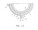
- the first end 34 of the electrical conductor 16, 420 may be located or otherwise remain in the channel 14 as shown in FIG. 12 .
- the channel 14 may (but need not) extend to the rim 26 of the curved outer surface 12.
- the electrical conductor 16, 420 does not extend out of the channel 14, the conductor 16, 420 is accessible by the orthopaedic surgeon to determine proper seating of the acetabular cup 20 as discussed above.
- the rim 26 of the curved outer surface 12 may be positioned above the acetabular margin of the patient's acetabulum such that the electrical conductor 16, 420 is accessible by the surgeon.
- the orthopaedic surgeon may lift the electrical conductor 16, 420 from the channel 14 if such repositioning of the electrical conductor 16, 420 is required.
- the electrical conductor 16, 420 may be removed from the channel 14 by the orthopaedic surgeon in the manner described above.
- an orthopaedic surgeon may determine whether the orthopaedic prosthesis 10 (e.g., the acetabular cup 20) is properly seated by measuring a circuit parameter of the circuit formed by the electrical conductor 16 and the electrically conductive outer surface 12 or electrically conductive trace 400 or by the multiple electrical conductors 424, 426 of the electrical assembly 420, depending on the particular embodiment.
- the particular circuit parameter measured may be embodied as any type of circuit parameter capable of determining whether the switch 18 is in the first, non-conductive state or the second, conductive state.
- the circuit parameter may be embodied as resistance, impedance, reactance, capacitance, inductance, resistor-capacitor (RC) time constant, or other circuit parameter.
- the measurement circuit 200 may include a circuit device 450 for measuring a circuit.
- the type of circuit device 450 used may depend on the particular circuit parameter to be measured.
- the circuit device 450 is embodied as a capacitor and the measurement circuit 200 is configured to determine the state of the switch 18 based on the RC constant of the circuit formed by the electrical conductor 16, 420 and the electrical outer surface 12 or trace 400.
- the resistor of the RC circuit may be embodied as, or otherwise include, the resistance of the electrical conductor 16, Rp, and the resistance of the outer surface 12, Rc.
- an additional resistor may be used.
- the circuit device 450 may form a portion of the measurement circuit 200 or may be included in the electrical conductor 16, 420 (e.g., positioned inline with the electrical conductors).
- the conductive state of the switch 18, and thereby the proper seating of the orthopaedic prosthesis 10 may be determined using any suitable circuit parameter including, but not limited to resistance, impedance, reactance, capacitance, inductance, and RC time constant,
- a method 500 for determining whether the orthopaedic prosthesis 10 is properly seated begins with step 502.
- the orthopaedic prosthesis 10 is positioned in the surgically-prepared bone of the patient.
- the prosthesis 10 is embodied as the acetabular cup 20
- the cup 20 is positioned in the patient's surgically-prepared acetabulum.
- the orthopaedic surgeon measures the circuit parameter of the circuit attached to the prosthesis 10 (step 504), which is formed by the electrical conductor 16 and the electrically conductive outer surface 12 or electrically conductive trace 400 or by the multiple electrical conductors 424, 426 of the electrical assembly 420, depending on the particular embodiment.
- the measured circuit parameter is compared to a predetermined threshold value, and proper seating of the orthopaedic prostheses 10 is determined based on whether the measured circuit parameter has a predetermined relationship with the threshold value.
- the measured circuit parameter may be compared to a predetermined resistance or impedance value in step 506 and proper seating of the orthopaedic prosthesis may be verified if the measured resistance/impedance is below a the predetermined threshold resistance/impedance.
- the position of the orthopaedic prosthesis 10 is adjusted in step 508. Additionally, in some embodiments, the bone of the patient may be re-shaped again in step 508. For example, in embodiments in which the prosthesis 10 is embodied as an acetabular cup 20, the acetabulum of the patient may be re-reamed in step 508 to provide a better match to the acetabular cup 20.
- the circuit parameter is subsequently again measured in step 306. If, however, the measured circuit parameter does have the predetermined relationship with the threshold value (e.g., is less than or greater than the threshold value) the orthopaedic prosthesis 10 is considered to be properly seated. As such, the orthopaedic surgeon may trim or remove the electrical conductor 16, 420 in step 510.
Landscapes
- Health & Medical Sciences (AREA)
- Orthopedic Medicine & Surgery (AREA)
- Transplantation (AREA)
- Heart & Thoracic Surgery (AREA)
- Cardiology (AREA)
- Oral & Maxillofacial Surgery (AREA)
- Engineering & Computer Science (AREA)
- Biomedical Technology (AREA)
- Vascular Medicine (AREA)
- Life Sciences & Earth Sciences (AREA)
- Animal Behavior & Ethology (AREA)
- General Health & Medical Sciences (AREA)
- Public Health (AREA)
- Veterinary Medicine (AREA)
- Physical Education & Sports Medicine (AREA)
- Prostheses (AREA)
Abstract
Description
- The present invention relates to orthopaedic prostheses, and particularly to orthopaedic prostheses having an indicator coupled thereto for providing an indication when the prosthesis is properly seated.
- Orthopaedic prostheses are implanted in patients by orthopaedic surgeons to, for example, correct or otherwise alleviate bone and/or soft tissue loss, trauma damage, and/or deformation of the bone(s) of the patients. Orthopaedic prostheses replace a portion of or the complete joint of a patient. For example, the orthopaedic prosthesis may replace the patient's hip, shoulder, ankle, knee or other joint. In the case of a hip replacement, the orthopaedic prosthesis includes an acetabular cup, which is secured to the surgically-prepared acetabulum of the patient. The acetabular cup replaces the natural bearing surface of the acetabulum with a new bearing surface for the natural or prosthetic head of the patient's femur.
- During the orthopaedic surgical procedure, a surgeon initially prepares the patient's bone to receive the orthopaedic prosthesis. For example, in the case of a hip orthopaedic surgical procedure, the surgeon may initially ream the patient's acetabulum. The orthopaedic prosthesis is subsequently coupled to the patient's surgically-prepared bone. Depending on the particular orthopaedic surgical procedure, the type of orthopaedic prosthesis, and/or other factors, it may be difficult for the surgeon to determine when the orthopaedic prosthesis is fully seated into the patient's bone. For example, it may be difficult for the orthopaedic surgeon to visually confirm when particular portions of the orthopaedic prosthesis have contacted the patient's bone.
- This invention provides a component of an orthopaedic joint prosthesis (which could be a cup component, for example an acetabular component of a hip joint prosthesis), which has an outer surface, an electrical conductor, an electrically conductive trace formed on the outer surface, and a switch. The outer surface may be configured to confront a portion of a patient's bone (especially a hollow portion, for example the acetabulum) when the component is implanted in the patient. The outer surface may include a channel defined therein. The electrical conductor may be positioned in the channel. The switch may be located at a first location on the outer surface. The switch may have a first state in which an electrical connection between the electrical conductor and the electrically conductive trace is broken and a second state in which an electrical connection between the electrical conductor and the electrically conductive trace is established.
- In some embodiments, the electrically conductive trace is located in the channel of the outer surface. Additionally, in some embodiments, the electrically conductive trace may include an electrically conductive pad formed on the outer surface at the first location. The electrically conductive trace may extend from the first location to a rim of the outer surface in some embodiments. Additionally, in some embodiments, the electrical conductor has a first end located in the channel toward a rim of the outer surface. Alternatively, in other embodiments, the first end may extend out of the channel at the rim of the outer surface. In some embodiments, the channel may extend from the first location to the rim of the outer surface.
- In some embodiments, the switch may be embodied as a second end of the electrical conductor. In such embodiments, the second end of the electrical conductor may extend out of the channel at the first location of the outer surface and may be capable of being positioned such that the second end comes into contact with the electrically conductive trace when the first location of the outer surface is pressed against the patient's acetabulum. In some embodiments, the switch is configured such that the switch is positioned in the second state when the first location of the outer surface is pressed against the patient's acetabulum.
- In some embodiments, the switch may be embodied as a push-button switch. In such embodiments, the push-button switch being may be biassed to the first state. Additionally, the push-button switch may be configured such that the push-button switch is positioned in the second state when the first location of the outer surface is pressed against the patient's acetabulum.
- The invention also provides a component of an orthopaedic joint prosthesis (which could be a cup component, for example an acetabular component of a hip joint prosthesis), which may have an outer surface configured to confront a portion of a patient's bone (especially a hollow portion, for example the acetabulum) when the component is implanted in the patient and an electrical conductor assembly. The outer surface may include a channel defined therein and the electrical conductor assembly may be positioned in the channel. The electrical conductor assembly may include a first conductor and a second conductor. Each of the first and second conductors may have a first end extending out of the channel at a first location on the outer surface. The first ends of the first and second conductors may form a switch having a first state in which an electrical connection between the first and second conductors is broken and a second state in which an electrical connection between the first and second conductors is established.
- In some embodiments, the first conductor may be embodied as a wire and the second conductor may be embodied as a shielding formed around the wire. The second conductor may be secured to the outer surface at the first location in some embodiments. For example, in some embodiments, the outer surface may include an electrically conductive pad formed thereon. The second conductor may be electrically connected to the electrically conductive pad.
- In some embodiments, each of the first and second conductors may include a second end opposite the first end. The second ends of the first and second conductors may be located in the channel. Additionally, in some embodiments, the switch may be configured such that the switch is positioned in the second state when the first location of the outer surface is pressed against the patient's acetabulum.
- Devices provided by the invention can be used in a method of implanting a component of an orthopaedic joint prosthesis (for example a cup component such as an acetabular component of a hip joint prosthesis) in a patient, which may include placing the component in a recess in the patient's bone (for example in the acetabulum) of the patient and measuring a circuit parameter of a circuit secured to the component. The circuit parameter may be measured by, for example, measuring a time constant of the circuit. Additionally or alternatively, the circuit parameter may be measured by, for example, measuring an impedance of the circuit. Additionally or alternatively, the circuit parameter may be measured by, for example, determining the state of a switch of the circuit.
- Embodiments of the invention are described below by way of example with reference to the accompanying drawings, in which:
-
FIG. 1 is a perspective view of one embodiment of an orthopaedic prosthesis having a seating indicator coupled thereto; -
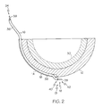
FIG. 2 is a cross-sectional view of the orthopaedic prosthesis ofFIG. 1 ; -
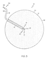
FIG. 3 is a plan view of the outer surface of the orthopaedic prosthesis ofFIG. 1 ; -
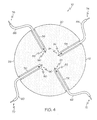
FIG. 4 is a plan view of the outer surface of another embodiment of the orthopaedic prosthesis ofFIG. 1 ; -
FIG. 5 is a plan view of the outer surface of another embodiment of the orthopaedic prosthesis ofFIG. 1 ; -
FIG. 6 is a plan view of the outer surface of another embodiment of the orthopaedic prosthesis ofFIG. 1 ; -
FIG. 7 is a simplified block diagram of one embodiment of a measuring circuit for determining proper seating of an orthopedic prosthesis having a seating indicator; -
FIG. 8 is a simplified flowchart of a method for determining whether an orthopaedic prosthesis is seated; and -
FIG. 9 is a plan view of the outer surface of another embodiment of the orthopaedic prosthesis ofFIG. 1 ; -
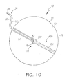
FIG. 10 is a plan view of the outer surface of another embodiment of the orthopaedic prosthesis ofFIG. 1 ; -
FIG. 11 is a cross-sectional view of another embodiment of the orthopaedic prosthesis ofFIG. 1 ; -
FIG. 12 is a cross-sectional view of another embodiment of the orthopaedic prosthesis ofFIG. 1 ; -
FIG. 13 is a simplified block diagram of another embodiment of a measuring circuit for determining proper seating of an orthopedic prosthesis having a seating indicator; and -
FIG. 14 is a simplified flowchart of another method for determining whether an orthopaedic prosthesis is seated. - Terms representing anatomical references, such as anterior, posterior, medial, lateral, superior, inferior, etcetera, may be used throughout this disclosure in reference to both the orthopaedic implants described herein and a patient's natural anatomy. Such terms have well-understood meanings in both the study of anatomy and the field of orthopaedics. Use of such anatomical reference terms in the specification and claims is intended to be consistent with their well-understood meanings unless noted otherwise.
- Referring to the drawings,
FIG. 1 shows a cup componentorthopaedic prosthesis 10 which has a curvedouter surface 12 having achannel 14 defined therein, anelectrical conductor 16 positioned in thechannel 14, and aswitch 18 positioned at a location of the curvedouter surface 12 and electrically coupled to theelectrical conductor 16. In the embodiment shown in the drawing, theorthopaedic prosthesis 10 is embodied as anacetabular cup 20, but may be embodied as other prostheses in other embodiments. For example, theorthopaedic prosthesis 10 may be embodied as any orthopaedic prosthesis having a curved outer surface, such as a shoulder or ankle prosthesis, which can present difficulties for an orthopaedic surgeon to determine whether the prosthesis is properly seated into the patient's bone (e.g., when particular portions of theprosthesis 10 contact the patient's bone) due to visual limitations. Accordingly, although theorthopaedic prosthesis 10 is discussed in detail below in regard to anacetabular cup 20, it should be appreciated that such features and description may be equally applicable to other orthopaedic prostheses including shoulder and ankle prostheses. - The
acetabular cup 20 includes the curvedouter surface 12, a curvedinner surface 22, and arim surface 24 extending from the edge or rim 26 of the curvedouter surface 12 to the edge or rim 28 of the curvedinner surface 22. Theacetabular cup 20 may be formed from any suitable material capable of being secured to the acetabulum of a patient and supporting a natural or artificial head portion of the patient's femur. For example, theacetabular cup 20 may be formed from a ceramic material, a polymer material, a titanium alloy, or other implantable metal material. Theacetabular cup 20 shown in the drawing is a monoblock prosthesis formed of a single piece and configured to be implanted into the patient's acetabulum without the use of bone cement. As such, theacetabular cup 20 does not include mounting holes defined through the inner andouter surfaces acetabular cup 20 may include any number of mounting holes, which are commonly used with bone screws to secure thecup 20 to the patient's bone. - In other embodiments, the
acetabular cup 20 may be formed from a number of separate parts. For example, in some embodiments, theacetabular cup 20 may include a bearing 30 (seeFIG. 2 ) configured to be received in acavity 32 defined by the innercurved surface 22. In such embodiments, thebearing 30 provides an artificial surface on which the natural or artificial head portion of the femur of the patient may articulate. Thebearing 30 may be formed from any material suitable for such purpose. For example, the bearing 30 may be formed from a metallic material, a ceramic material, a polymeric material such as polyethylene or ultra-high molecular weight polypropylene (UHMWPE), and/or the like. - In the embodiment in the drawing, the curved
outer surface 12 is electrically conductive. For example, in some embodiments, the curvedouter surface 12 may have an electrical conductivity of 5 siemens per metre or greater. In embodiments in which acetabularcup 20 is formed from a non-electrically conductive material, such as a ceramic or polymer material, theacetabular cup 20 may include an electrically conductive coating or texture applied to theouter surface 12 so as to form the electrically conductiveouter surface 12. In some embodiments, the conductive coating may be configured to also enhance bone growth. Additionally, even in embodiments in which theacetabular cup 20 is formed from an electrically conductive material, such as a metallic material, the electrically conductive coating may also be applied to theouter surface 12 of thecup 20. - As discussed above, the
outer surface 12 of theacetabular cup 20 includes thechannel 14 defined therein. Thechannel 14 extends from therim 26 of theouter surface 12 to apredetermined location 13 of theouter surface 12. Thelocation 13 to which thechannel 14 extends may be any location of interest on theouter surface 12 that contacts the patient's bone when theacetabular cup 20 is properly seated therein. For example, as shown inFIGS. 2 and3 , in some embodiments, thechannel 14 may extend from therim 26 to a location of theouter surface 12 substantially corresponding to the apex of the dome-shapedouter surface 12. - The
electrical conductor 16 is positioned in thechannel 14 and includes afirst end 34 that extends out of thechannel 14 at therim 26 of theouter surface 12. In the embodiment shown in the drawings, theelectrical conductor 16 extends out of the channel 14 a length sufficient enough such that theelectrical conductor 16 may be grasped by an orthopaedic surgeon while theacetabular cup 20 is fully seated into the patient's bone. - In the embodiment shown in the drawings, the
electrical conductor 16 is embodied as a wire, but may be embodied as other types of electrical conductors in other embodiments such as an electrical trace, rod, or other electrically conductive path. Theelectrical conductor 16 can include a non-electricallyconductive cladding 36 and an electrically conductiveinner core 38, which is surrounded by thecladding 36. In one particular embodiment, thecladding 36 is formed from a non-electrically conductive polymer cladding and the electrically conductiveinner core 38 is formed from an electrically conductive polymer. However, theelectrical conductor 16 may be formed from other bio-compatible materials in other embodiments. Thecladding 36 provides an amount of electrical isolation to theinner core 38. To access theinner core 38, thecladding 36 may be stripped back or otherwise removed such that theinner core 38 extends therefrom as shown at thefirst end 34 of theelectrical conductor 16 inFIG. 1 . - The
electrical conductor 16 may be held in place in thechannel 14 by frictional forces or using an adhesive. For example, in some embodiments, thechannel 14 may have a width slightly larger than the outer width of thecladding 36 such that theelectrical conductor 16 may be pressed into thechannel 14 and held in place via frictional forces. Alternatively, a bio-compatible adhesive may be used to secure theelectrical conductor 16 in thechannel 14. In some embodiments, the adhesive may be semi-permanent such that theelectrical conductor 16 may be removed from thechannel 14 by application of an appropriate amount of force as discussed below in regard toFIG. 8 . - As shown in
FIG. 2 , theswitch 18 is positioned at thepredetermined location 13 of the curved outer surface 12 (i.e., the location of interest that contacts the patient's bone when thecup 20 is properly seated). In the embodiment shown in the drawings, theswitch 18 is positioned near the apex of the dome-shapedouter surface 12. Theswitch 18 may be a simple switch or a complex switch. For example, in the embodiment shown in the drawings, theswitch 18 is embodied as asecond end 40 of theelectrical conductor 16. However, in other embodiments as discussed in more detail below with reference toFIGS. 5 and 6 , theswitch 18 may be embodied as a more complex switch that is electrically coupled toelectrical conductor 16. - The
switch 18 shown inFIGS. 1 to 4 is formed from thesecond end 40 of theelectrical conductor 16 by removal of thenon-conductive cladding 36, which exposes anend 42 of theinner core 38. Theend 42 of theinner core 38 is positioned to extend out of thechannel 14 and over a portion of the electrically conductiveouter surface 12 without contacting thesurface 12. However, when theacetabular cup 20 is properly seated in the patient's acetabulum, theend 42 of theinner core 38 is pressed against the electrically conductiveouter surface 12 by the patient's bone thereby establishing a connection between theelectrical conductor 16 and theouter surface 12. - As such, the
switch 18 includes two states, a non-conductive state and a conductive state. In the first state, theend 42 of theinner core 38 is spaced apart from the electrically conductiveouter surface 12 and no electrical connection is established between theelectrical conductor 16 and theouter surface 12. Theswitch 18 is positioned in the first state prior to implantation of theacetabular cup 20. In the second state, theend 42 of theinner core 38 is in contact with the electrically conductiveouter surface 12 and an electrical connection is established between theelectrical conductor 16 and theouter surface 12. As such, as discussed in more detail below, an orthopaedic surgeon may determine whether theacetabular cup 20 is properly seated (i.e., whether thepredetermined location 13 of theouter surface 12 is in contact with the patient's bone) by measuring the resistance between theouter surface 12 of theacetabular cup 20 and thefirst end 34 of the electrical conductor. A measured resistance value less than a predetermined threshold value is indicative of proper seating of theacetabular cup 20 because theouter surface 12 is in contact with the patient's bone causing theswitch 18 to be positioned in the second, conductive state. - Although the embodiment shown in
FIGS. 1 to 3 includes asingle switch 18, theacetabular cup 20 may include any number of switches in other embodiments. Each switch may be used to detect whether a corresponding location of theouter surface 12 is in contact with the patient's bone to thereby determine proper seating of thecup 20. For example, in the embodiment shown inFIG. 4 , theacetabular cup 20 includes fourchannels channel 14, defined in the electrically conductiveouter surface 12. Anelectrical conductor electrical conductor 16, is positioned in eachrespective channel electrical conductors first end respective channel rim 26 of theouter surface 12. Additionally, eachelectrical conductor second end respective switch channels outer surface 12 in a symmetrical pattern in the embodiment shown inFIG. 4 , it should be appreciated that thechannels corresponding switch outer surface 12. - In some embodiments, the
switch 18 may be embodied as a complex switch. For example, in some embodiments, as shown inFIGS. 5 and 6 , theswitch 18 may be embodied as a push-button switch 100. The push-button switch 100 may be embodied as any type of push-button switch. For example, the push-button switch 100 may be a plunger-type switch having a plunger configured to be depressed when the switch contacts the patient's bone. Alternatively, the push-button switch 100 may be a dome-type switch having a dome or ceiling configured to be collapsed when the switch contacts the patient's bone. Regardless, the push-button switch 100 is positioned in a recessedarea 102 defined in theouter surface 12 of theacetabular cup 20 at thepredetermined location 13. The push-button switch 100 may be secured in the recessedarea 102 using any suitable adhesive or connector. In such embodiments, thechannel 14 extends from therim 26 of theouter surface 12 to the recessedarea 102. - The push-button switch 100 is electrically coupled to the
electrical conductor 16 and to the electrically conductiveouter surface 12. As discussed above in regard to theswitch 18, the push-button switch 100 includes two states, a non-conductive state and a conductive state. In the first state, no electrical connection is established between theelectrical conductor 16 and theouter surface 12. In the second state, the switch 100 is activated (e.g., the switch 100 contacts a portion of the patient's bone) and an electrical connection is established between theelectrical conductor 16 and theouter surface 12. - As discussed above, the
acetabular cup 20 may include any number ofswitches 18, 100 to detect whether corresponding locations of the outer surface are in contact with the patient's bone. For example, as shown inFIG. 6 , theacetabular cup 20 may include four push-button switches areas outer surface 12 includes a number ofchannels areas channel 130 extends from the recessedarea 120 to the recessedarea 122. Thechannel 132 extends from the recessedarea 122 to the recessedarea 124. Thechannel 134 extends from the recessedarea 124 to the recessedarea 126. Thechannel 136 extends from the recessedarea 126 to the recessedarea 120. Additionally, achannel 138 extends from therim 26 of the electrically conductiveouter surface 12 to the recessedarea 120. Anelectrical conductor 139 is positioned in thechannel 138 and is electrically coupled to the push-button switch 110. Anelectrical conductor 140 is positioned in thechannel 130 and is electrically coupled to theswitches electrical conductor 142 is positioned in thechannel 132 and is electrically coupled to theswitches electrical conductor 144 is positioned in thechannel 134 and is electrically coupled to theswitches electrical conductor 146 is positioned in thechannel 136 and is electrically coupled to theswitch 116. Theelectrical conductor 146 extends from thechannel 136, through thechannel 138, and extends out of thechannel 138 at therim 26 of the electrically conductiveouter surface 12. - It should be appreciated that the embodiment of
FIG. 6 , includes twoconductors channel 138. In such embodiments, theswitches outer surface 12. Additionally, theouter surface 12 may (but need not) be electrically conductive. For example, in the embodiment shown inFIG. 6 , theouter surface 12 is not electrically conductive. In such embodiments, each of theswitches electrical conductors switch electrical conductors acetabular cup 20 is properly seated in such embodiments by measuring the continuity (or resistance) of the electrical path defined by theelectrical conductors acetabular cup 20 is indicated when the electrical path is completed or broken depending on the type ofswitches - Although the
acetabular cup 20 shown inFIG. 6 includes fourseparate switches cup 20 may include a greater or smaller number of switches in other embodiments. For example, in some embodiments, theacetabular cup 20 may include a single switch similar to the embodiment shown inFIG. 5 . However, because the single switch is not coupled to theouter surface 12 in such embodiments, an additional electrical conductor is included and extends out of thechannel 14. Additionally, as discussed above in regard toFIG. 6 , theouter surface 12 may not be electrically conductive in such embodiments. However, in other embodiments, theouter surface 12 may be electrically conductive and eachswitch outer surface 12. In such embodiments, theacetabular cup 20 includes a separate channel and electrical conductor for each switch similar to the embodiment described above with reference toFIG. 4 . - Referring now to
FIG. 7 , an orthopaedic surgeon may determine whether theacetabular cup 20 is properly seated by measuring the resistance between the electrical conductor 16 (orconductors FIG. 4 ) and the electrically conductiveouter surface 12 of the cup (or between two conductors in the embodiment ofFIG. 6 ). To do so, ameasurement circuit 200 may be used. Themeasurement circuit 200 may be embodied as any type of circuit or device capable of measuring the resistance or impedance of a circuit. Themeasurement circuit 200 includes afirst measurement probe 202, which is electrically coupled to thefirst end 34 of theelectrical conductor 16. Themeasurement circuit 200 also includes asecond measurement probe 204, which is electrically coupled to the electrically conductiveouter surface 12 of the acetabular cup 20 (or the other electrical conductor in the embodiment ofFIG. 6 ). Themeasurement circuit 200 measures the resistance between the these two points. A measured resistance below a predetermined threshold is indicative that theswitch 18 has been positioned in the second state (i.e., thepredetermined location 13 has contacted the patient's bone) and theacetabular cup 20 is properly positioned. As shown inFIG. 7 , the predetermined resistance threshold includes or otherwise accounts for the resistance of theelectrical conductor 16, Rp, and the resistance of theouter surface 12, Rc. - Referring now to
FIG. 8 , amethod 300 for determining whether theorthopaedic prosthesis 10 is properly seated begins withstep 302. Instep 302, theorthopaedic prosthesis 10 is positioned in the surgically-prepared bone of the patient. For example, in embodiments in which theprosthesis 10 is embodied as theacetabular cup 20, thecup 20 is positioned in the patient's surgically-prepared acetabulum. After theprosthesis 10 has been so positioned, the orthopaedic surgeon measures the resistance between theelectrical conductor 16 and the electrically conductiveouter surface 12 of the acetabular cup 20 (or between the two electrical conductors in embodiments similar to the embodiment ofFIG. 6 ) instep 304. Instep 306, the measured resistance value is compared to the predetermined resistance threshold value. If the measured value is greater than the predetermined resistance threshold value, the position of theorthopaedic prosthesis 10 is adjusted instep 308. Additionally, in some embodiments, the bone of the patient may be re-shaped again instep 308. For example, in embodiments in which theprosthesis 10 is embodied as anacetabular cup 20, the acetabulum of the patient may be re-reamed instep 308 to provide a better match to theacetabular cup 20. The resistance between theelectrical conductor 16 and theouter surface 12 is again measured instep 306. If, however, the measured resistance is determined to be less than the predetermined resistance threshold instep 306, the orthopaedic prosthesis is considered to be properly seated. As such, the orthopaedic surgeon may trim or remove theelectrical conductor 16. For example, in embodiments in which theelectrical conductor 16 is secured in thechannel 14 by frictional forces, the orthopaedic surgeon may remove theelectrical conductor 16 from thechannel 14 by pulling on theend 34 of theelectrical conductor 16. - It should be appreciated that while the
outer surface 12 has been described in relation to the embodiments above as electrically conductive, only a portion of theouter surface 12 may be electrically conductive in other embodiments. For example, as shown inFIGS. 9 and10 , theouter surface 12 may include an electrically conductive trace orcoating 400. In such embodiments, the areas of theouter surface 12 not covered by thetrace 400 may be electrically non-conductive. For example, theacetabular cup 20 may be formed from an electrically non-conductive material, such as a ceramic or polymer material. Thetrace 400 may be embodied as an electrically conductive coating or texture applied to theouter surface 12 so as to form the electricallyconductive trace 400. - In the embodiments shown in
FIGS. 9 and10 , the electricallyconductive trace 400 includes an electricallyconductive pad 402 and an elongated electricallyconductive trace 404 electrically coupled to thepad 402. The electricallyconductive pad 402 is located at thepredetermined location 13 on theouter surface 12. Thepad 402 may have any shape and size capable of being contacted by theend 42 of theinner core 38 of theelectrical conductor 16. In this way, theend 42 and the electricallyconductive pad 402 form theswitch 18. As discussed in detail above, theswitch 18 includes two states, a non-conductive state and a conductive state. In the first state, theend 42 of theinner core 38 is spaced apart from the electricallyconductive pad 402 and no electrical connection is established between theelectrical conductor 16 and the electricallyconductive trace 400. Theswitch 18 is positioned in the first state prior to implantation of theacetabular cup 20. In the second state, theend 42 of theinner core 38 is in contact with the electricallyconductive pad 402 and an electrical connection is established between theelectrical conductor 16 and the electricallyconductive trace 400. - The elongated, electrically
conductive trace 404 extends from the electricallyconductive pad 402 toward therim 26 of theouter surface 12. In some embodiments, the electricallyconductive trace 404 may extend to therim 26 of theouter surface 12. However, in other embodiments, thetrace 404 may end short of therim 26 while still being accessible by the orthopaedic surgeon when theacetabular cup 20 is implanted in the patient. In the particular embodiment shown inFIG. 9 , the electricallyconductive trace 404 is defined or otherwise formed in thechannel 14. For example, aninner surface 408 of theouter surface 12 that defines thechannel 14 may be coated with an electrically conductive material to form thetrace 404. As such, thechannel 14 houses theelectrical conductor 16 while also forming an electrical conduit to thepad 402. However, in other embodiments, the electricallyconductive trace 404 may be defined in locations on theouter surface 12 other than thechannel 14. For example, as shown inFIG. 10 , the electricallyconductive trace 404 may extend from the electricallyconductive pad 402 toward therim 26 along a relatively straight or curved path separate form thechannel 14. - In use, as discussed above, an orthopaedic surgeon may determine whether the orthopaedic prosthesis 10 (e.g., acetabular cup 20) is properly seated (i.e., whether the
predetermined location 13 of theouter surface 12 is pressed against the patient's bone) by measuring the resistance, impedance, reactance, capacitance, inductance, or other circuit parameter between theinner core 38 of theelectrical conductor 16 and theconductive trace 400. A measured circuit parameter value having a predetermined relationship with a predetermined threshold value (e.g., the measured circuit parameter is greater or lesser than the predetermined threshold value) is indicative of proper seating of theorthopaedic prosthesis 10 because theouter surface 12 is pressed against the patient's bone causing theswitch 18 to be positioned in the second, conductive state. - Referring now to
FIG. 11 , in some embodiments, theelectrical conductor 16 may have more than one internal, electrical conductor (e.g., inner core 38). For example, in some embodiments theelectrical conductor 16 may be embodied as anelectrical conductor assembly 420 having multipleelectrical conductors 422. Theassembly 420 shown inFIG. 11 includes two internal,electrical conductors electrical conductors electrical conductors electrical conductor electrical conductors end 428 at thesecond end 40 of theelectrical conductor assembly 420. The ends 428 of theelectrical conductors channel 14 at thepredetermined location 13 and are spaced apart from each other to form theswitch 18. In some embodiments, one of theconductors 424, 426 (e.g., the shielding conductor) is attached or otherwise secured to theouter surface 12 at thepredetermined location 13 to secure theend 428 ofconductor secured conductor - As discussed above, the
ends 428 of theelectrical conductors switch 18, which includes two states, a non-conductive state and a conductive state. In the first state, theends 428 of theelectrical conductors electrical conductor 424 and theelectrical conductor 426. Theswitch 18 is positioned in the first state prior to implantation of theacetabular cup 20. In the second state, theends 428 of theelectrical conductors electrical conductor 16 and the electricallyconductive trace 400. As such, an orthopaedic surgeon may determine whether the orthopaedic prosthesis 10 (e.g., acetabular cup 20) is properly seated (i.e., whether thepredetermined location 13 of theouter surface 12 is pressed against the patient's bone) by measuring the resistance, impedance, reactance, capacitance, inductance, or other circuit parameter between theelectrical conductors first end 34 of theelectrical conductor assembly 420. - In each of the embodiments described above, the
first end 34 of theelectrical conductor channel 14 at therim 26 of the curvedouter surface 12. However, in other embodiments, thefirst end 34 of theelectrical conductor channel 14 as shown inFIG. 12 . In such embodiments, thechannel 14 may (but need not) extend to therim 26 of the curvedouter surface 12. Although theelectrical conductor channel 14, theconductor acetabular cup 20 as discussed above. For example, in some embodiments, therim 26 of the curvedouter surface 12 may be positioned above the acetabular margin of the patient's acetabulum such that theelectrical conductor orthopaedic prosthesis 10, the orthopaedic surgeon may lift theelectrical conductor channel 14 if such repositioning of theelectrical conductor acetabular cup 20 has been properly positioned, theelectrical conductor channel 14 by the orthopaedic surgeon in the manner described above. - Referring now to
FIG. 13 , an orthopaedic surgeon may determine whether the orthopaedic prosthesis 10 (e.g., the acetabular cup 20) is properly seated by measuring a circuit parameter of the circuit formed by theelectrical conductor 16 and the electrically conductiveouter surface 12 or electricallyconductive trace 400 or by the multipleelectrical conductors electrical assembly 420, depending on the particular embodiment. The particular circuit parameter measured may be embodied as any type of circuit parameter capable of determining whether theswitch 18 is in the first, non-conductive state or the second, conductive state. For example, the circuit parameter may be embodied as resistance, impedance, reactance, capacitance, inductance, resistor-capacitor (RC) time constant, or other circuit parameter. - As shown in
FIG. 13 , in some embodiments, themeasurement circuit 200 may include acircuit device 450 for measuring a circuit. The type ofcircuit device 450 used may depend on the particular circuit parameter to be measured. For example, in one particular embodiment, thecircuit device 450 is embodied as a capacitor and themeasurement circuit 200 is configured to determine the state of theswitch 18 based on the RC constant of the circuit formed by theelectrical conductor outer surface 12 ortrace 400. In such embodiments, the resistor of the RC circuit may be embodied as, or otherwise include, the resistance of theelectrical conductor 16, Rp, and the resistance of theouter surface 12, Rc. In some embodiments, an additional resistor may be used. Thecircuit device 450 may form a portion of themeasurement circuit 200 or may be included in theelectrical conductor 16, 420 (e.g., positioned inline with the electrical conductors). As such, it should be appreciated that the conductive state of theswitch 18, and thereby the proper seating of theorthopaedic prosthesis 10, may be determined using any suitable circuit parameter including, but not limited to resistance, impedance, reactance, capacitance, inductance, and RC time constant, - Referring now to
FIG. 14 , amethod 500 for determining whether theorthopaedic prosthesis 10 is properly seated begins withstep 502. Instep 502, theorthopaedic prosthesis 10 is positioned in the surgically-prepared bone of the patient. For example, in embodiments in which theprosthesis 10 is embodied as theacetabular cup 20, thecup 20 is positioned in the patient's surgically-prepared acetabulum. After theprosthesis 10 has been so positioned, the orthopaedic surgeon measures the circuit parameter of the circuit attached to the prosthesis 10 (step 504), which is formed by theelectrical conductor 16 and the electrically conductiveouter surface 12 or electricallyconductive trace 400 or by the multipleelectrical conductors electrical assembly 420, depending on the particular embodiment. Instep 506, the measured circuit parameter is compared to a predetermined threshold value, and proper seating of theorthopaedic prostheses 10 is determined based on whether the measured circuit parameter has a predetermined relationship with the threshold value. For example, in embodiments in which the measured circuit parameter is embodied as resistance or impedance of the circuit, the measured circuit parameter may be compared to a predetermined resistance or impedance value instep 506 and proper seating of the orthopaedic prosthesis may be verified if the measured resistance/impedance is below a the predetermined threshold resistance/impedance. - If the measured circuit parameter does not have the predetermined relationship with the threshold value, the position of the
orthopaedic prosthesis 10 is adjusted instep 508. Additionally, in some embodiments, the bone of the patient may be re-shaped again instep 508. For example, in embodiments in which theprosthesis 10 is embodied as anacetabular cup 20, the acetabulum of the patient may be re-reamed instep 508 to provide a better match to theacetabular cup 20. The circuit parameter is subsequently again measured instep 306. If, however, the measured circuit parameter does have the predetermined relationship with the threshold value (e.g., is less than or greater than the threshold value) theorthopaedic prosthesis 10 is considered to be properly seated. As such, the orthopaedic surgeon may trim or remove theelectrical conductor step 510.
Claims (15)
- A component of an orthopaedic joint prosthesis, comprising:an outer surface configured to confront a portion of a patient's bone when the component is implanted in the patient, the outer surface including a channel defined therein,an electrical conductor positioned in the channel,an electrically conductive trace formed on the outer surface, anda switch located at a first location on the outer surface, the switch having a first state in which an electrical connection between the electrical conductor and the electrically conductive trace is broken and a second state in which an electrical connection between the electrical conductor and the electrically conductive trace is established.
- The component of claim 1, in which the electrically conductive trace is located in the channel of the outer surface.
- The component of claim 1, in which the electrically conductive trace comprises an electrically conductive pad formed on the outer surface at the first location.
- The component of claim 1, in which the electrically conductive trace extends from the first location to a rim of the outer surface.
- The component of claim 1, in which the electrical conductor has a first end located in the channel toward a rim of the outer surface.
- The component of claim 5, in which the switch comprises a second end of the electrical conductor, the second end of the electrical conductor extending out of the channel at the first location of the outer surface and positionable such that the second end comes into contact with the electrically conductive trace when the first location of the outer surface is pressed against the patient's bone.
- The component of claim 1, in which the switch is configured such that the switch is positioned in the second state when the first location of the outer surface is pressed against the patient's bone.
- The component of claim 1, in which the switch comprises a push-button switch, the push-button switch being biased to the first state.
- The component of claim 8, in which the push-button switch is configured such that the push-button switch is positioned in the second state when the first location of the outer surface is pressed against the patient's bone.
- The component of claim 1, in which the channel extends from the first location to a rim of the outer surface.
- A component of an orthopaedic joint prosthesis, comprising:an outer surface configured to confront a portion of a patient's bone when the component is implanted in the patient, the outer surface including a channel defined therein,an electrical conductor assembly positioned in the channel, the electrical conductor assembly including a first conductor and a second conductor, each of the first and second conductors having an end extending out of the channel at a first location on the outer surface, the ends of the first and second conductors forming a switch having a first state in which an electrical connection between the first and second conductors is broken and a second state in which an electrical connection between the first and second conductors is established.
- The component of claim 11, in which the first conductor comprises a wire and the second conductor comprises a shielding formed around the wire.
- The component of claim 11, in which the second conductor is secured to the outer surface at the first location, and in which the outer surface preferably includes an electrically conductive pad formed thereon, the second conductor being electrically connected to the electrically conductive pad.
- The component of claim 11, in which each end of the first and second conductor comprises a second end, and in which each of the first and second conductors includes a first end opposite the second end, the first ends of the first and second conductors being located in the channel.
- The component of claim 11, in which the switch is configured such that the switch is positioned in the second state when the first location of the outer surface is pressed against the patient's bone.
Applications Claiming Priority (1)
| Application Number | Priority Date | Filing Date | Title |
|---|---|---|---|
| US12/820,762 US8403995B2 (en) | 2008-12-18 | 2010-06-22 | Device and method for determining proper seating of an orthopaedic prosthesis |
Publications (2)
| Publication Number | Publication Date |
|---|---|
| EP2399551A1 true EP2399551A1 (en) | 2011-12-28 |
| EP2399551B1 EP2399551B1 (en) | 2013-01-23 |
Family
ID=44509762
Family Applications (1)
| Application Number | Title | Priority Date | Filing Date |
|---|---|---|---|
| EP11169970A Active EP2399551B1 (en) | 2010-06-22 | 2011-06-15 | Device for determining seating of an orthopaedic prosthesis |
Country Status (2)
| Country | Link |
|---|---|
| US (2) | US8403995B2 (en) |
| EP (1) | EP2399551B1 (en) |
Families Citing this family (3)
| Publication number | Priority date | Publication date | Assignee | Title |
|---|---|---|---|---|
| US10838406B2 (en) | 2013-02-11 | 2020-11-17 | The Aerospace Corporation | Systems and methods for the patterning of material substrates |
| US8679189B1 (en) * | 2013-02-11 | 2014-03-25 | Amendia Inc. | Bone growth enhancing implant |
| GB2529203B (en) * | 2014-08-13 | 2016-09-28 | James Wallace Mcminn Derek | Acetabular cup prosthesis |
Citations (4)
| Publication number | Priority date | Publication date | Assignee | Title |
|---|---|---|---|---|
| DE19932242A1 (en) * | 1998-07-06 | 2000-01-13 | Biomet Merck Deutschland Gmbh | Relative spacing display device for hip joint prosthesis |
| US20020049394A1 (en) * | 2000-08-25 | 2002-04-25 | The Cleveland Clinic Foundation | Apparatus and method for assessing loads on adjacent bones |
| US20050010302A1 (en) * | 2003-07-11 | 2005-01-13 | Terry Dietz | Telemetric tibial tray |
| US20060047283A1 (en) * | 2004-08-25 | 2006-03-02 | Evans Boyd M Iii | In-vivo orthopedic implant diagnostic device for sensing load, wear, and infection |
Family Cites Families (25)
| Publication number | Priority date | Publication date | Assignee | Title |
|---|---|---|---|---|
| DE1918299B2 (en) | 1969-04-10 | 1972-04-13 | Kraus, Werner, Dipl.-Ing., 8000 München | Splint for guiding and healing fractured bones |
| JPS63318939A (en) | 1987-06-22 | 1988-12-27 | Kurashiki Chuo Biyouin | Acetabulum angle meter |
| DE58900119D1 (en) | 1988-02-04 | 1991-06-27 | Protek Ag | SURGICAL INSTRUMENT FOR THE INSERTION OF THE SPIRIT PROSTHESES. |
| FR2634644B1 (en) | 1988-07-28 | 1991-02-01 | Fayard Jean Philippe | PROSTHESIS CUP |
| IE880739L (en) | 1988-09-14 | 1990-03-14 | Malcolm Hugh Farmer | Alignment of hip joint sockets in hip joint replacement |
| US5030236A (en) * | 1989-06-19 | 1991-07-09 | Intermedics Orthopedics, Inc. | Apparatus for enhancing biointegration of bony and endoprosthesis structures |
| FR2649005B1 (en) | 1989-07-03 | 1991-10-25 | Fischer Louis | COTYLOIDIAN PROSTHESIS IN PLASTICS |
| US5141512A (en) | 1989-08-28 | 1992-08-25 | Farmer Malcolm H | Alignment of hip joint sockets in hip joint replacement |
| US5318571A (en) | 1992-05-14 | 1994-06-07 | Benson Gail M | Method and apparatus for simplifying total hip arthroplasty |
| EP0668063B1 (en) | 1993-08-09 | 1999-07-14 | Tschirren, Ernst jun. | Shell for joint prosthesis, especially hip joint prosthesis and insert for use with the shell |
| DE59509561D1 (en) | 1995-05-18 | 2001-10-04 | Sulzer Orthopaedie Ag Baar | Artificial joint shell |
| US5824078A (en) | 1996-03-11 | 1998-10-20 | The Board Of Trustees Of The University Of Arkansas | Composite allograft, press, and methods |
| US5879401A (en) | 1996-05-17 | 1999-03-09 | Johnson & Johnson Professional, Inc. | Acetabular trial |
| US5904688A (en) | 1997-12-30 | 1999-05-18 | Bristol-Myers Squibb Co. | Orthopaedic assembly including an acetabular cup and cup inserter |
| JP3086805B1 (en) | 1999-05-20 | 2000-09-11 | 悟 矢野 | Hip replacement device |
| US6623488B1 (en) | 2000-03-16 | 2003-09-23 | Leone Innovations Corporation | Pelvic alignment assembly |
| US6302890B1 (en) | 2000-03-16 | 2001-10-16 | Leone Innovations Corporation | Pelvic alignment assembly |
| BR0214094A (en) | 2001-11-02 | 2004-09-28 | Eugene Sherry | Bone Surgery Apparatus and Methods |
| US7005573B2 (en) | 2003-02-13 | 2006-02-28 | Parker-Hannifin Corporation | Composite EMI shield |
| CA2588739A1 (en) | 2004-12-02 | 2006-06-08 | Smith & Nephew, Inc. | Systems for providing a reference plane for mounting an acetabular cup |
| KR100706030B1 (en) | 2005-04-12 | 2007-04-11 | 한국과학기술원 | Acetabular cup navigation system using reference mechanism and Acetabular cup navigation method using same |
| EP1954204A4 (en) | 2005-11-18 | 2010-09-29 | Robert Lye | Surgical alignment guide |
| US7328131B2 (en) | 2006-02-01 | 2008-02-05 | Medtronic, Inc. | Implantable pedometer |
| DE102007004584A1 (en) | 2007-01-24 | 2008-08-07 | Kisielinski, Kasimir, Dipl.-Ing. | Apparatus and method for measuring the position of a first part to another part and use of such a device |
| JP5443335B2 (en) * | 2007-04-19 | 2014-03-19 | スミス アンド ネフュー インコーポレーテッド | Artificial joint |
-
2010
- 2010-06-22 US US12/820,762 patent/US8403995B2/en active Active
-
2011
- 2011-06-15 EP EP11169970A patent/EP2399551B1/en active Active
-
2012
- 2012-12-18 US US13/718,411 patent/US8747482B2/en active Active
Patent Citations (4)
| Publication number | Priority date | Publication date | Assignee | Title |
|---|---|---|---|---|
| DE19932242A1 (en) * | 1998-07-06 | 2000-01-13 | Biomet Merck Deutschland Gmbh | Relative spacing display device for hip joint prosthesis |
| US20020049394A1 (en) * | 2000-08-25 | 2002-04-25 | The Cleveland Clinic Foundation | Apparatus and method for assessing loads on adjacent bones |
| US20050010302A1 (en) * | 2003-07-11 | 2005-01-13 | Terry Dietz | Telemetric tibial tray |
| US20060047283A1 (en) * | 2004-08-25 | 2006-03-02 | Evans Boyd M Iii | In-vivo orthopedic implant diagnostic device for sensing load, wear, and infection |
Also Published As
| Publication number | Publication date |
|---|---|
| US8747482B2 (en) | 2014-06-10 |
| US8403995B2 (en) | 2013-03-26 |
| US20100262256A1 (en) | 2010-10-14 |
| US20130110114A1 (en) | 2013-05-02 |
| EP2399551B1 (en) | 2013-01-23 |
Similar Documents
| Publication | Publication Date | Title |
|---|---|---|
| US5326363A (en) | Provisional implant | |
| US5814050A (en) | Hip offset-inset apparatus and method | |
| US9943420B2 (en) | Liner having an integrated electrode | |
| US5318571A (en) | Method and apparatus for simplifying total hip arthroplasty | |
| US5989259A (en) | Femoral calcar stop for use with femoral stem inserter | |
| US20140249535A1 (en) | Acetabular cup positioning device | |
| AU2022285762B2 (en) | Independently implantable sensors for orthopedic implants | |
| CA2795344C (en) | Hip implant | |
| US8075629B2 (en) | Orthopaedic prosthesis having a seating indicator | |
| US8747482B2 (en) | Device and method for determining proper seating of an orthopaedic prosthesis | |
| US20120116527A1 (en) | Surgical prostheses | |
| US20170086981A1 (en) | Femoral hip stem | |
| Bilir et al. | In-body antenna design for next generation hip implants | |
| CN207785320U (en) | Assembly type acetabulum prosthesis positioning device based on 3D printing technology | |
| Guyen et al. | Tripolar versus conventional total hip implants range of motion to impingement test | |
| JP2024518851A (en) | Kit for installation of prosthetic components and/or biological implants |
Legal Events
| Date | Code | Title | Description |
|---|---|---|---|
| AK | Designated contracting states |
Kind code of ref document: A1 Designated state(s): AL AT BE BG CH CY CZ DE DK EE ES FI FR GB GR HR HU IE IS IT LI LT LU LV MC MK MT NL NO PL PT RO RS SE SI SK SM TR |
|
| AX | Request for extension of the european patent |
Extension state: BA ME |
|
| PUAI | Public reference made under article 153(3) epc to a published international application that has entered the european phase |
Free format text: ORIGINAL CODE: 0009012 |
|
| 17P | Request for examination filed |
Effective date: 20120627 |
|
| GRAP | Despatch of communication of intention to grant a patent |
Free format text: ORIGINAL CODE: EPIDOSNIGR1 |
|
| RIC1 | Information provided on ipc code assigned before grant |
Ipc: A61F 2/30 20060101AFI20120719BHEP Ipc: A61F 2/34 20060101ALI20120719BHEP |
|
| GRAS | Grant fee paid |
Free format text: ORIGINAL CODE: EPIDOSNIGR3 |
|
| GRAA | (expected) grant |
Free format text: ORIGINAL CODE: 0009210 |
|
| AK | Designated contracting states |
Kind code of ref document: B1 Designated state(s): AL AT BE BG CH CY CZ DE DK EE ES FI FR GB GR HR HU IE IS IT LI LT LU LV MC MK MT NL NO PL PT RO RS SE SI SK SM TR |
|
| REG | Reference to a national code |
Ref country code: GB Ref legal event code: FG4D |
|
| REG | Reference to a national code |
Ref country code: CH Ref legal event code: EP Ref country code: CH Ref legal event code: NV Representative=s name: E. BLUM AND CO. AG PATENT- UND MARKENANWAELTE , CH |
|
| REG | Reference to a national code |
Ref country code: AT Ref legal event code: REF Ref document number: 594541 Country of ref document: AT Kind code of ref document: T Effective date: 20130215 Ref country code: CH Ref legal event code: NV Representative=s name: E. BLUM AND CO. AG PATENT- UND MARKENANWAELTE , CH Ref country code: CH Ref legal event code: EP |
|
| REG | Reference to a national code |
Ref country code: IE Ref legal event code: FG4D |
|
| REG | Reference to a national code |
Ref country code: DE Ref legal event code: R096 Ref document number: 602011000831 Country of ref document: DE Effective date: 20130328 |
|
| REG | Reference to a national code |
Ref country code: AT Ref legal event code: MK05 Ref document number: 594541 Country of ref document: AT Kind code of ref document: T Effective date: 20130123 |
|
| REG | Reference to a national code |
Ref country code: LT Ref legal event code: MG4D |
|
| REG | Reference to a national code |
Ref country code: NL Ref legal event code: VDEP Effective date: 20130123 |
|
| PG25 | Lapsed in a contracting state [announced via postgrant information from national office to epo] |
Ref country code: AT Free format text: LAPSE BECAUSE OF FAILURE TO SUBMIT A TRANSLATION OF THE DESCRIPTION OR TO PAY THE FEE WITHIN THE PRESCRIBED TIME-LIMIT Effective date: 20130123 Ref country code: BE Free format text: LAPSE BECAUSE OF FAILURE TO SUBMIT A TRANSLATION OF THE DESCRIPTION OR TO PAY THE FEE WITHIN THE PRESCRIBED TIME-LIMIT Effective date: 20130123 Ref country code: IS Free format text: LAPSE BECAUSE OF FAILURE TO SUBMIT A TRANSLATION OF THE DESCRIPTION OR TO PAY THE FEE WITHIN THE PRESCRIBED TIME-LIMIT Effective date: 20130523 Ref country code: SE Free format text: LAPSE BECAUSE OF FAILURE TO SUBMIT A TRANSLATION OF THE DESCRIPTION OR TO PAY THE FEE WITHIN THE PRESCRIBED TIME-LIMIT Effective date: 20130123 Ref country code: LT Free format text: LAPSE BECAUSE OF FAILURE TO SUBMIT A TRANSLATION OF THE DESCRIPTION OR TO PAY THE FEE WITHIN THE PRESCRIBED TIME-LIMIT Effective date: 20130123 Ref country code: BG Free format text: LAPSE BECAUSE OF FAILURE TO SUBMIT A TRANSLATION OF THE DESCRIPTION OR TO PAY THE FEE WITHIN THE PRESCRIBED TIME-LIMIT Effective date: 20130423 Ref country code: ES Free format text: LAPSE BECAUSE OF FAILURE TO SUBMIT A TRANSLATION OF THE DESCRIPTION OR TO PAY THE FEE WITHIN THE PRESCRIBED TIME-LIMIT Effective date: 20130504 Ref country code: NO Free format text: LAPSE BECAUSE OF FAILURE TO SUBMIT A TRANSLATION OF THE DESCRIPTION OR TO PAY THE FEE WITHIN THE PRESCRIBED TIME-LIMIT Effective date: 20130423 |
|
| PG25 | Lapsed in a contracting state [announced via postgrant information from national office to epo] |
Ref country code: LV Free format text: LAPSE BECAUSE OF FAILURE TO SUBMIT A TRANSLATION OF THE DESCRIPTION OR TO PAY THE FEE WITHIN THE PRESCRIBED TIME-LIMIT Effective date: 20130123 Ref country code: SI Free format text: LAPSE BECAUSE OF FAILURE TO SUBMIT A TRANSLATION OF THE DESCRIPTION OR TO PAY THE FEE WITHIN THE PRESCRIBED TIME-LIMIT Effective date: 20130123 Ref country code: FI Free format text: LAPSE BECAUSE OF FAILURE TO SUBMIT A TRANSLATION OF THE DESCRIPTION OR TO PAY THE FEE WITHIN THE PRESCRIBED TIME-LIMIT Effective date: 20130123 Ref country code: PL Free format text: LAPSE BECAUSE OF FAILURE TO SUBMIT A TRANSLATION OF THE DESCRIPTION OR TO PAY THE FEE WITHIN THE PRESCRIBED TIME-LIMIT Effective date: 20130123 Ref country code: NL Free format text: LAPSE BECAUSE OF FAILURE TO SUBMIT A TRANSLATION OF THE DESCRIPTION OR TO PAY THE FEE WITHIN THE PRESCRIBED TIME-LIMIT Effective date: 20130123 Ref country code: GR Free format text: LAPSE BECAUSE OF FAILURE TO SUBMIT A TRANSLATION OF THE DESCRIPTION OR TO PAY THE FEE WITHIN THE PRESCRIBED TIME-LIMIT Effective date: 20130424 Ref country code: PT Free format text: LAPSE BECAUSE OF FAILURE TO SUBMIT A TRANSLATION OF THE DESCRIPTION OR TO PAY THE FEE WITHIN THE PRESCRIBED TIME-LIMIT Effective date: 20130523 |
|
| PG25 | Lapsed in a contracting state [announced via postgrant information from national office to epo] |
Ref country code: RS Free format text: LAPSE BECAUSE OF FAILURE TO SUBMIT A TRANSLATION OF THE DESCRIPTION OR TO PAY THE FEE WITHIN THE PRESCRIBED TIME-LIMIT Effective date: 20130123 Ref country code: HR Free format text: LAPSE BECAUSE OF FAILURE TO SUBMIT A TRANSLATION OF THE DESCRIPTION OR TO PAY THE FEE WITHIN THE PRESCRIBED TIME-LIMIT Effective date: 20130123 |
|
| PG25 | Lapsed in a contracting state [announced via postgrant information from national office to epo] |
Ref country code: EE Free format text: LAPSE BECAUSE OF FAILURE TO SUBMIT A TRANSLATION OF THE DESCRIPTION OR TO PAY THE FEE WITHIN THE PRESCRIBED TIME-LIMIT Effective date: 20130123 Ref country code: CZ Free format text: LAPSE BECAUSE OF FAILURE TO SUBMIT A TRANSLATION OF THE DESCRIPTION OR TO PAY THE FEE WITHIN THE PRESCRIBED TIME-LIMIT Effective date: 20130123 Ref country code: DK Free format text: LAPSE BECAUSE OF FAILURE TO SUBMIT A TRANSLATION OF THE DESCRIPTION OR TO PAY THE FEE WITHIN THE PRESCRIBED TIME-LIMIT Effective date: 20130123 Ref country code: RO Free format text: LAPSE BECAUSE OF FAILURE TO SUBMIT A TRANSLATION OF THE DESCRIPTION OR TO PAY THE FEE WITHIN THE PRESCRIBED TIME-LIMIT Effective date: 20130123 Ref country code: SK Free format text: LAPSE BECAUSE OF FAILURE TO SUBMIT A TRANSLATION OF THE DESCRIPTION OR TO PAY THE FEE WITHIN THE PRESCRIBED TIME-LIMIT Effective date: 20130123 |
|
| PG25 | Lapsed in a contracting state [announced via postgrant information from national office to epo] |
Ref country code: CY Free format text: LAPSE BECAUSE OF FAILURE TO SUBMIT A TRANSLATION OF THE DESCRIPTION OR TO PAY THE FEE WITHIN THE PRESCRIBED TIME-LIMIT Effective date: 20130123 |
|
| PLBE | No opposition filed within time limit |
Free format text: ORIGINAL CODE: 0009261 |
|
| STAA | Information on the status of an ep patent application or granted ep patent |
Free format text: STATUS: NO OPPOSITION FILED WITHIN TIME LIMIT |
|
| PG25 | Lapsed in a contracting state [announced via postgrant information from national office to epo] |
Ref country code: IT Free format text: LAPSE BECAUSE OF FAILURE TO SUBMIT A TRANSLATION OF THE DESCRIPTION OR TO PAY THE FEE WITHIN THE PRESCRIBED TIME-LIMIT Effective date: 20130123 |
|
| 26N | No opposition filed |
Effective date: 20131024 |
|
| PG25 | Lapsed in a contracting state [announced via postgrant information from national office to epo] |
Ref country code: MC Free format text: LAPSE BECAUSE OF FAILURE TO SUBMIT A TRANSLATION OF THE DESCRIPTION OR TO PAY THE FEE WITHIN THE PRESCRIBED TIME-LIMIT Effective date: 20130123 |
|
| REG | Reference to a national code |
Ref country code: DE Ref legal event code: R097 Ref document number: 602011000831 Country of ref document: DE Effective date: 20131024 |
|
| PG25 | Lapsed in a contracting state [announced via postgrant information from national office to epo] |
Ref country code: MT Free format text: LAPSE BECAUSE OF FAILURE TO SUBMIT A TRANSLATION OF THE DESCRIPTION OR TO PAY THE FEE WITHIN THE PRESCRIBED TIME-LIMIT Effective date: 20130123 |
|
| PG25 | Lapsed in a contracting state [announced via postgrant information from national office to epo] |
Ref country code: SM Free format text: LAPSE BECAUSE OF FAILURE TO SUBMIT A TRANSLATION OF THE DESCRIPTION OR TO PAY THE FEE WITHIN THE PRESCRIBED TIME-LIMIT Effective date: 20130123 |
|
| PG25 | Lapsed in a contracting state [announced via postgrant information from national office to epo] |
Ref country code: TR Free format text: LAPSE BECAUSE OF FAILURE TO SUBMIT A TRANSLATION OF THE DESCRIPTION OR TO PAY THE FEE WITHIN THE PRESCRIBED TIME-LIMIT Effective date: 20130123 |
|
| PG25 | Lapsed in a contracting state [announced via postgrant information from national office to epo] |
Ref country code: HU Free format text: LAPSE BECAUSE OF FAILURE TO SUBMIT A TRANSLATION OF THE DESCRIPTION OR TO PAY THE FEE WITHIN THE PRESCRIBED TIME-LIMIT; INVALID AB INITIO Effective date: 20110615 Ref country code: LU Free format text: LAPSE BECAUSE OF NON-PAYMENT OF DUE FEES Effective date: 20130615 Ref country code: MK Free format text: LAPSE BECAUSE OF FAILURE TO SUBMIT A TRANSLATION OF THE DESCRIPTION OR TO PAY THE FEE WITHIN THE PRESCRIBED TIME-LIMIT Effective date: 20130123 |
|
| REG | Reference to a national code |
Ref country code: FR Ref legal event code: PLFP Year of fee payment: 6 |
|
| REG | Reference to a national code |
Ref country code: FR Ref legal event code: PLFP Year of fee payment: 7 |
|
| REG | Reference to a national code |
Ref country code: FR Ref legal event code: PLFP Year of fee payment: 8 |
|
| PG25 | Lapsed in a contracting state [announced via postgrant information from national office to epo] |
Ref country code: AL Free format text: LAPSE BECAUSE OF FAILURE TO SUBMIT A TRANSLATION OF THE DESCRIPTION OR TO PAY THE FEE WITHIN THE PRESCRIBED TIME-LIMIT Effective date: 20130123 |
|
| PGFP | Annual fee paid to national office [announced via postgrant information from national office to epo] |
Ref country code: DE Payment date: 20250429 Year of fee payment: 15 |
|
| PGFP | Annual fee paid to national office [announced via postgrant information from national office to epo] |
Ref country code: GB Payment date: 20250501 Year of fee payment: 15 |
|
| PGFP | Annual fee paid to national office [announced via postgrant information from national office to epo] |
Ref country code: FR Payment date: 20250508 Year of fee payment: 15 |
|
| PGFP | Annual fee paid to national office [announced via postgrant information from national office to epo] |
Ref country code: IE Payment date: 20250509 Year of fee payment: 15 |
|
| PGFP | Annual fee paid to national office [announced via postgrant information from national office to epo] |
Ref country code: CH Payment date: 20250701 Year of fee payment: 15 |