EP2398563B1 - Ventilation-duct fire damper and method - Google Patents
Ventilation-duct fire damper and method Download PDFInfo
- Publication number
- EP2398563B1 EP2398563B1 EP10707309.0A EP10707309A EP2398563B1 EP 2398563 B1 EP2398563 B1 EP 2398563B1 EP 10707309 A EP10707309 A EP 10707309A EP 2398563 B1 EP2398563 B1 EP 2398563B1
- Authority
- EP
- European Patent Office
- Prior art keywords
- frame
- cone
- outer section
- fire
- closing
- Prior art date
- Legal status (The legal status is an assumption and is not a legal conclusion. Google has not performed a legal analysis and makes no representation as to the accuracy of the status listed.)
- Active
Links
Images

Classifications
-
- F—MECHANICAL ENGINEERING; LIGHTING; HEATING; WEAPONS; BLASTING
- F24—HEATING; RANGES; VENTILATING
- F24F—AIR-CONDITIONING; AIR-HUMIDIFICATION; VENTILATION; USE OF AIR CURRENTS FOR SCREENING
- F24F11/00—Control or safety arrangements
- F24F11/70—Control systems characterised by their outputs; Constructional details thereof
- F24F11/72—Control systems characterised by their outputs; Constructional details thereof for controlling the supply of treated air, e.g. its pressure
- F24F11/74—Control systems characterised by their outputs; Constructional details thereof for controlling the supply of treated air, e.g. its pressure for controlling air flow rate or air velocity
- F24F11/76—Control systems characterised by their outputs; Constructional details thereof for controlling the supply of treated air, e.g. its pressure for controlling air flow rate or air velocity by means responsive to temperature, e.g. bimetal springs
-
- A—HUMAN NECESSITIES
- A62—LIFE-SAVING; FIRE-FIGHTING
- A62C—FIRE-FIGHTING
- A62C2/00—Fire prevention or containment
- A62C2/06—Physical fire-barriers
- A62C2/18—Sliding dampers
- A62C2/20—Sliding dampers at 90 degrees to the plane of the opening
-
- F—MECHANICAL ENGINEERING; LIGHTING; HEATING; WEAPONS; BLASTING
- F16—ENGINEERING ELEMENTS AND UNITS; GENERAL MEASURES FOR PRODUCING AND MAINTAINING EFFECTIVE FUNCTIONING OF MACHINES OR INSTALLATIONS; THERMAL INSULATION IN GENERAL
- F16L—PIPES; JOINTS OR FITTINGS FOR PIPES; SUPPORTS FOR PIPES, CABLES OR PROTECTIVE TUBING; MEANS FOR THERMAL INSULATION IN GENERAL
- F16L5/00—Devices for use where pipes, cables or protective tubing pass through walls or partitions
- F16L5/02—Sealing
- F16L5/04—Sealing to form a firebreak device
-
- F—MECHANICAL ENGINEERING; LIGHTING; HEATING; WEAPONS; BLASTING
- F16—ENGINEERING ELEMENTS AND UNITS; GENERAL MEASURES FOR PRODUCING AND MAINTAINING EFFECTIVE FUNCTIONING OF MACHINES OR INSTALLATIONS; THERMAL INSULATION IN GENERAL
- F16L—PIPES; JOINTS OR FITTINGS FOR PIPES; SUPPORTS FOR PIPES, CABLES OR PROTECTIVE TUBING; MEANS FOR THERMAL INSULATION IN GENERAL
- F16L55/00—Devices or appurtenances for use in, or in connection with, pipes or pipe systems
- F16L55/10—Means for stopping flow in pipes or hoses
- F16L55/1026—Fire protection devices
-
- F—MECHANICAL ENGINEERING; LIGHTING; HEATING; WEAPONS; BLASTING
- F24—HEATING; RANGES; VENTILATING
- F24F—AIR-CONDITIONING; AIR-HUMIDIFICATION; VENTILATION; USE OF AIR CURRENTS FOR SCREENING
- F24F13/00—Details common to, or for air-conditioning, air-humidification, ventilation or use of air currents for screening
- F24F13/02—Ducting arrangements
- F24F13/06—Outlets for directing or distributing air into rooms or spaces, e.g. ceiling air diffuser
- F24F13/062—Outlets for directing or distributing air into rooms or spaces, e.g. ceiling air diffuser having one or more bowls or cones diverging in the flow direction
-
- F—MECHANICAL ENGINEERING; LIGHTING; HEATING; WEAPONS; BLASTING
- F24—HEATING; RANGES; VENTILATING
- F24F—AIR-CONDITIONING; AIR-HUMIDIFICATION; VENTILATION; USE OF AIR CURRENTS FOR SCREENING
- F24F11/00—Control or safety arrangements
- F24F11/30—Control or safety arrangements for purposes related to the operation of the system, e.g. for safety or monitoring
- F24F11/32—Responding to malfunctions or emergencies
- F24F11/33—Responding to malfunctions or emergencies to fire, excessive heat or smoke
- F24F11/35—Responding to malfunctions or emergencies to fire, excessive heat or smoke by closing air passages
Definitions
- the invention relates to a fire damper of a ventilation duct according to the preamble of claim 1.
- the invention also relates to a method according to the preamble of claim 7.
- Fire dampers are usually located in a ventilation duct between two different fire compartments. Fire dampers aim at preventing fire from spreading from one fire compartment to another fire compartment.
- Patent FI55767 describes a fire damper to be connected to a supply or exhaust air duct of a ventilation installation.
- the fire damper has an operation which forces a valve regulating element to close the valve in the event of fire in a flow duct.
- the valve comprises a conical collar and a conical disc fitted in the conical collar. Between the conical collar and the conical disc is formed a flow duct the cross-sectional area of which can be adjusted by moving the disc in relation to the collar in the axial direction.
- the disc has a threaded hole in which is fitted a first end of a threaded stem. The second end of the threaded stem is connected to a bail the ends of which are fastened in the conical collar.
- a trigger and closing mechanism of the fire damper which in the event of fire performs an automatic quick-closing of the disc against the conical collar.
- the valve Via the bail, the valve can be fastened in a frame by rotating.
- the frame comprises a cylindrical section to be installed in the supply or exhaust air duct and an outer flange which comes directly against a wall surface. It is possible to use a fire insulating seal between the outer flange of the frame coming against the wall surface and the conical collar of the valve.
- Patent EP1095672 also describes a fire damper of a ventilation installation.
- the principal structures of the valve and the frame are here equivalent to the ones of the valve and frame of the above patent FI55767 .
- the valve is fastened to the frame via an annular piece of heat-resistant material, being castable. Said annular piece forms the only mechanical connection between the conical collar of the valve and the frame surrounding it.
- the aim of the arrangement according to the invention is to minimise disadvantages related to prior-art arrangements or to eliminate them totally.
- the fire damper comprises a frame extending through a hole in a wall structure installable at the end of a ventilation duct and a valve installable in the frame.
- the frame comprises a substantially cylindrical inner section and a substantially flange-shaped outer section.
- the valve comprises a closing cone and a counter cone between which is formed a flow duct and a trigger mechanism with which the closing cone is triggered against the counter cone for closing the flow duct in the event of fire.
- the counter cone has a conical inner section and a split annular outer section.
- the fire damper utilises two fire insulating seals.
- the first fire insulating seal is located between the outer section of the counter cone of the valve and the outer section of the frame.
- the second fire insulating seal is located between the outer section of the frame and the outer surface surrounding the hole in the wall structure and the end of the ventilation duct.
- the fire damper according to the invention is inexpensive and simple to manufacture as well as easy to install and maintain.
- the use of elastic, heat-resistant fire insulating seals to seal leakages is a simple and cost-effective way to prevent fire from spreading via the fire damper to other spaces.
- the arrangement according to the invention is applicable to all wall structures.
- the use of the second fire insulating seal between the outer section of the frame and the outer surface surrounding the hole in the wall structure and the end of the ventilation duct protects the outer surface of the wall surrounding the hole in the wall structure from chipping. For instance, the surface of a plasterboard is easily chipped when the outer section of the frame in time rubs against the plasterboard. Then, a leakage can be created between the frame and the plasterboard, due to which the fire damper will not form a fire blockage as tight as required.
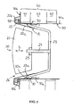
- Fig. 1 shows a schematic view of a fire damper of a ventilation duct according to the invention.
- the fire damper consists of a frame 10 which in connected to a ventilation duct 30 extending through a hole 40a. in .a wall structure 40 and of a valve 20 connected to the frame 10.
- the valve 20 comprises a closing cone 21, a counter cone 22, a bail 23 which is fixedly connected to the counter cone 22 in a connection point A, and a stem 24 with which the closing cone 21 is movably connected to the bail 23.
- the frame 10 of the fire damper comprises a substantially cylindrical inner section 10a and a substantially flange-shaped outer section 10b which has an inner surface and an outer surface.
- the inner section 10a of the frame 10 sets against the inner surface of the ventilation duct 30 and the outer section 10b of the frame sets against an outer surface 40b surrounding the hole 40a in the wall structure 40 and the end of the duct 30.
- the wall structure 40 here comprises an outer panel 41 and an inner panel 42 and an insulating layer 43 between them.
- the frame 10 is fastened of its inner section 10a in the duct 30 with fastening means 70, e.g. screws.
- the counter cone 22 of the valve 20 of the fire damper consists of a truncated conical inner section 22a and a split annular outer section 22b.
- the inner section 22a sets in the ventilation duct 30 and the outer section sets against the side surface 40b surrounding the hole 40a in the wall structure 40.
- Between the closing cone 21 and the counter cone 22 is formed a conical flow duct 26 from which air can enter the ventilation duct 30 or exit it.
- the stem 24 advantageously consists of a threaded tap, whereby the closing cone 21 includes a nut 25 in which the threaded tap 24 sets.
- the closing cone 21 is thus movable in the axial direction S in relation to the counter cone 22, whereby the area of the duct 26 between the closing cone 21 and the counter cone 22 is adjustable.
- first fire insulating seal 50 Between the outer section 22b of the counter cone 22 and the outer surface of the outer section 10b of the frame 10, there is a first fire insulating seal 50. Between the inner surface of the outer section 10b of the frame 10 and the side surface 40b surrounding the hole 40a in the wall structure 40 and the end of the duct 30, there is a second fire insulating seal 51. These seals 50, 51 are located in the axial direction S opposite each other on both sides of the outer section 10b of the frame. 10. Both fire insulating seals 50, 51 consist of an elastic material resistant to high temperatures, an example of which is the insulating material marketed with trademark Kerafix 2000 owned by a company called Trader-Koo Oy. The wall lead-in of the ventilation duct 30 is also sealed properly against the spreading of fire.
- the valve 20 can be fastened in the frame 10 by rotating such that slightly outwards deflected ends 23a of the bail 23 set against stoppers 10c in the inner section 10a of the frame 10.
- the stoppers 10c are advantageously designed such that rotating the valve 20 to the frame 10 simultaneously presses down the first fire insulating seal 50 within the outer section 22b of the counter cone 22 tightly against the outer section 10a of the frame 10.
- the valve 20 thus supports itself to the frame 10 via two support locations at a distance from each other in the axial direction S.
- the first support location is formed of two support points between the ends 23a of the bail 23 and the inner section 10a of the frame.
- the second support location is formed via a circular support point formed by the first fire insulating seal 50 between the outer section 22b of the counter cone 22 and the outer section 10b of the frame 10.
- Fig. 2 shows a trigger mechanism applicable to the fire damper according to Fig. 1 in its excited state
- Fig. 3 shows the trigger mechanism as triggered.
- This trigger mechanism is known as such from the above patent F155767.
- the trigger mechanism 60 comprises .a diaphragm spring 61 installed around the threaded tap 24, which supports itself of its one end to the end of the threaded tap 24 in a washer 62 fastened e.g. with a pin and of its other end on the inner surface of a bottom 21a of the closing cone 21.
- the trigger mechanism 60 also comprises a flange 63 fastened onto the outer surface of the bottom 21a of the closing cone 21 e.g. with rivets 65, which includes a formed part 64 closing the nut 25 within itself.
- the nut 25 is fastened in the formed part 64 of the flange 63 with a solder joint 66 which forms a fuse melting in a specific temperature.
- the diaphragm spring 61 is pressed down and ready to trigger the fire damper as soon as the fuse 66 has melted.
- Figs. 2 and 3 show a trigger mechanism applicable to the fire damper according to the invention but, from the viewpoint of the invention, it is possible to use any trigger mechanism known by those skilled in the art.
Landscapes
- Engineering & Computer Science (AREA)
- General Engineering & Computer Science (AREA)
- Mechanical Engineering (AREA)
- Chemical & Material Sciences (AREA)
- Combustion & Propulsion (AREA)
- Health & Medical Sciences (AREA)
- Public Health (AREA)
- Business, Economics & Management (AREA)
- Emergency Management (AREA)
- Physics & Mathematics (AREA)
- Fluid Mechanics (AREA)
- Air-Flow Control Members (AREA)
Description
- The invention relates to a fire damper of a ventilation duct according to the preamble of claim 1.
- The invention also relates to a method according to the preamble of claim 7.
- Fire dampers are usually located in a ventilation duct between two different fire compartments. Fire dampers aim at preventing fire from spreading from one fire compartment to another fire compartment.
- Patent
FI55767 - Patent
EP1095672 also describes a fire damper of a ventilation installation. The principal structures of the valve and the frame are here equivalent to the ones of the valve and frame of the above patentFI55767 - Another known fire damper is described in
FR 2371557 - The aim of the arrangement according to the invention is to minimise disadvantages related to prior-art arrangements or to eliminate them totally.
- The principal characteristics of a fire damper of a ventilation duct according to the invention are presented in the characterising part of claim 1.
- The principal characteristics of a method according to the invention are presented in the characterising part of claim 6.
- Other characteristics of the invention are presented in the dependent claims.
- The fire damper according to the invention comprises a frame extending through a hole in a wall structure installable at the end of a ventilation duct and a valve installable in the frame. The frame comprises a substantially cylindrical inner section and a substantially flange-shaped outer section. The valve comprises a closing cone and a counter cone between which is formed a flow duct and a trigger mechanism with which the closing cone is triggered against the counter cone for closing the flow duct in the event of fire. The counter cone has a conical inner section and a split annular outer section. The fire damper utilises two fire insulating seals. The first fire insulating seal is located between the outer section of the counter cone of the valve and the outer section of the frame. The second fire insulating seal is located between the outer section of the frame and the outer surface surrounding the hole in the wall structure and the end of the ventilation duct.
- The fire damper according to the invention is inexpensive and simple to manufacture as well as easy to install and maintain. The use of elastic, heat-resistant fire insulating seals to seal leakages is a simple and cost-effective way to prevent fire from spreading via the fire damper to other spaces.
- The arrangement according to the invention is applicable to all wall structures.
- The use of the second fire insulating seal between the outer section of the frame and the outer surface surrounding the hole in the wall structure and the end of the ventilation duct protects the outer surface of the wall surrounding the hole in the wall structure from chipping. For instance, the surface of a plasterboard is easily chipped when the outer section of the frame in time rubs against the plasterboard. Then, a leakage can be created between the frame and the plasterboard, due to which the fire damper will not form a fire blockage as tight as required.
- The invention will now be described with reference to the figures of the accompanying drawings.
-
-
Fig. 1 shows a schematic view of a fire damper of a ventilation duct according to the invention. -
Fig. 2 shows a trigger mechanism applicable to the fire damper according toFig. 1 in its excited state. -
Fig. 3 shows the trigger mechanism ofFig. 2 as triggered. -
Fig. 1 shows a schematic view of a fire damper of a ventilation duct according to the invention. - The fire damper consists of a
frame 10 which in connected to aventilation duct 30 extending through a hole 40a. in .awall structure 40 and of avalve 20 connected to theframe 10. Thevalve 20 comprises aclosing cone 21, acounter cone 22, abail 23 which is fixedly connected to thecounter cone 22 in a connection point A, and astem 24 with which theclosing cone 21 is movably connected to thebail 23. - The
frame 10 of the fire damper comprises a substantially cylindricalinner section 10a and a substantially flange-shapedouter section 10b which has an inner surface and an outer surface. Theinner section 10a of theframe 10 sets against the inner surface of theventilation duct 30 and theouter section 10b of the frame sets against anouter surface 40b surrounding thehole 40a in thewall structure 40 and the end of theduct 30. Thewall structure 40 here comprises anouter panel 41 and aninner panel 42 and aninsulating layer 43 between them. Theframe 10 is fastened of itsinner section 10a in theduct 30 with fastening means 70, e.g. screws. - The
counter cone 22 of thevalve 20 of the fire damper consists of a truncated conicalinner section 22a and a split annularouter section 22b. Theinner section 22a sets in theventilation duct 30 and the outer section sets against theside surface 40b surrounding thehole 40a in thewall structure 40. Between theclosing cone 21 and thecounter cone 22 is formed aconical flow duct 26 from which air can enter theventilation duct 30 or exit it. Thestem 24 advantageously consists of a threaded tap, whereby theclosing cone 21 includes anut 25 in which the threadedtap 24 sets. Theclosing cone 21 is thus movable in the axial direction S in relation to thecounter cone 22, whereby the area of theduct 26 between theclosing cone 21 and thecounter cone 22 is adjustable. - Between the
outer section 22b of thecounter cone 22 and the outer surface of theouter section 10b of theframe 10, there is a firstfire insulating seal 50. Between the inner surface of theouter section 10b of theframe 10 and theside surface 40b surrounding thehole 40a in thewall structure 40 and the end of theduct 30, there is a secondfire insulating seal 51. Theseseals outer section 10b of the frame. 10. Bothfire insulating seals ventilation duct 30 is also sealed properly against the spreading of fire. - The
valve 20 can be fastened in theframe 10 by rotating such that slightly outwardsdeflected ends 23a of thebail 23 set againststoppers 10c in theinner section 10a of theframe 10. Thestoppers 10c are advantageously designed such that rotating thevalve 20 to theframe 10 simultaneously presses down the firstfire insulating seal 50 within theouter section 22b of thecounter cone 22 tightly against theouter section 10a of theframe 10. Thevalve 20 thus supports itself to theframe 10 via two support locations at a distance from each other in the axial direction S. The first support location is formed of two support points between theends 23a of thebail 23 and theinner section 10a of the frame. The second support location is formed via a circular support point formed by the firstfire insulating seal 50 between theouter section 22b of thecounter cone 22 and theouter section 10b of theframe 10. -
Fig. 2 shows a trigger mechanism applicable to the fire damper according toFig. 1 in its excited state, andFig. 3 shows the trigger mechanism as triggered. This trigger mechanism is known as such from the above patent F155767. Thetrigger mechanism 60 comprises .adiaphragm spring 61 installed around the threadedtap 24, which supports itself of its one end to the end of the threadedtap 24 in awasher 62 fastened e.g. with a pin and of its other end on the inner surface of a bottom 21a of the closingcone 21. Thetrigger mechanism 60 also comprises aflange 63 fastened onto the outer surface of the bottom 21a of the closingcone 21 e.g. withrivets 65, which includes a formedpart 64 closing thenut 25 within itself. Thenut 25 is fastened in the formedpart 64 of theflange 63 with a solder joint 66 which forms a fuse melting in a specific temperature. In the situation ofFig. 2 , thediaphragm spring 61 is pressed down and ready to trigger the fire damper as soon as thefuse 66 has melted. - In the event of fire and temperature rising in the
flow duct 26 to a temperature which melts thefuse 66, the locking between thenut 25 and the formedpart 64 of theflange 63 is released, whereby thespring 61 forces the freely-movable closing cone 21 to close theflow duct 26 totally, as shown inFig. 3 . -
Figs. 2 and 3 show a trigger mechanism applicable to the fire damper according to the invention but, from the viewpoint of the invention, it is possible to use any trigger mechanism known by those skilled in the art.
Claims (7)
- A fire damper of a ventilation duct comprises:- a frame (10) comprising a substantially cylindrical inner section (10a) and a substantially flange-shaped outer section (10b) which has an inner surface and an outer surface, said frame (10) being installed at the end of a ventilation duct (30) extending through a hole (40a) in a wall structure (40) such that the inner section (10a) of the frame (10) sets against the inner surface of the ventilation duct (30) and that the outer section (10b) of the frame (10) sets against a wall surface (40b) surrounding the hole (40a) in the wall structure (40) at the end of the ventilation duct (30),- a valve (20) comprising a closing cone (21) and a counter cone (22) between which is formed a flow duct (26), which counter cone (22) consists of a conical inner section (22a) and a split annular outer section (22b), and a trigger mechanism (60) with which the closing cone (21) is triggered against the counter cone (22) for closing the flow duct (26) between the closing cone (21) and the counter cone (22) in the event of fire, said valve (20) being installed in the frame (10) such that the inner section (22a) of the counter cone (22) sets within the inner section (10a) of the frame (10) and the outer section (22b) of the counter cone (22) sets against the outer section (10b) of the frame (10),- a first fire insulating seal (50) which is fastened within the split annular outer section (22b) of the counter cone (22), whereby the first fire insulating seal (50) seals the connection between the outer section (22b) of the counter cone (22) and the outer section (10b) of the frame (10),characterised in that the fire damper further comprises:- a second fire insulating seal (51) which is fastened on the inner surface of the outer section (10b) of the frame (10), whereby the second fire insulating seal (51) seals the connection between the outer section (10b) of the frame (10) and the wall surface (40b) surrounding the hole (40a) at the end of the ventilation duct (30).
- A fire damper according to claim 1, characterised in that the valve (20) further comprises a bail (23) which is fixedly connected to the counter cone (22) at a connection point (A) and a stem (24) with which the closing cone (21) is movably connected to the bail (23).
- A fire damper according to claim 2, characterised in that the stem (24) consists of a threaded tap which sets in a nut (25) in the closing cone (21), whereby the closing cone (21) is movable in the axial direction (S) in relation to the counter cone (22) for adjusting the area of the duct (26) between the closing cone (21) and the counter cone (22).
- A fire damper according to any one claims 1 - 3, characterised in that the trigger mechanism (60) comprises:- a diaphragm spring (61) installed around a threaded tap (24) which supports itself of its one end to a washer (62) fastened at the end of the threaded tap (24) and of its other end on the inner surface of a bottom (21a) of the closing cone (21), and- a flange (63) fastened on the outer surface of the bottom (21a) of the closing cone (21), which includes a formed part (64) closing the nut (25) within, in which formed part (64) the nut (25) is fastened with a solder joint (66) which solder joint (66) forms a fuse melting at a specific temperature, whereby the melting of the fuse (66) in the event of fire releases the locking between the nut (25) and the formed part (64) of the flange (63), as a result of which the diaphragm spring (61) forces the freely-movable closing cone (21) to close the flow duct (26) totally.
- A fire damper according to claim 4, characterised in that the fire damper further comprises fastening means (70) with which the frame (10) is fastened of its cylindrical inner section (10a) in the ventilation duct (30).
- A method in connection with a fire damper of a ventilation duct, characterised by:- installing a frame (10) of the fire damper at the end of a ventilation duct (30) extending through a hole (40a) in a wall structure (40) such that a substantially cylindrical inner section (10a) of the frame (10) sets within the ventilation duct (30) and that a substantially flange-shaped outer section (10b) of the frame (10) sets against a wall surface (40b) surrounding the hole (40a) in the wall structure (40) at the end of the ventilation duct (30),- installing a valve (20) in the frame (10), said valve (20) comprising a closing cone (21) and a counter cone (22) between which is formed a flow duct (26), which counter cone (22) consists of a conical inner section (22a) and a split annular outer section (22b), and a trigger mechanism (60) with which the closing cone (21) is triggered against the counter cone (22) for closing the flow duct (26) between the closing cone (21) and the counter cone (22) in the event of fire, the valve (20) being installed in the frame (10) such that the inner section (22a) of the counter cone (22) sets within the inner section (10a) of the frame (10) and the outer section (22b) of the counter cone (22) sets against the outer section (10b) of the frame (10),- installing a first fire insulating seal (50) between the outer section (22b) of the counter cone (22) and the outer section (10b) of the frame (10) in order to seal the connection between the outer section (22b) of the counter cone (22) and the outer section (10b) of the frame (10),characterised by:- installing a second fire insulating seal (51) between the outer section (10b) of the frame (10) and the wall surface (40b) surrounding the hole (40a) in the wall structure (40) at the end of the duct (30) in order to seal the connection between the outer section (10b) of the frame (10) and the wall surface (40b) surrounding the hole (40a) at the end of the ventilation duct (30).
- A method according to claim 6, characterised by fastening the frame (10) of its inner section (10b) in the ventilation duct (30) with fastening means (70).
Applications Claiming Priority (2)
| Application Number | Priority Date | Filing Date | Title |
|---|---|---|---|
| FI20095172A FI122823B (en) | 2009-02-23 | 2009-02-23 | Fire limiter for a ventilation duct and procedure |
| PCT/FI2010/050094 WO2010094835A1 (en) | 2009-02-23 | 2010-02-12 | Ventilation-duct fire damper and method |
Publications (2)
| Publication Number | Publication Date |
|---|---|
| EP2398563A1 EP2398563A1 (en) | 2011-12-28 |
| EP2398563B1 true EP2398563B1 (en) | 2014-10-29 |
Family
ID=40404670
Family Applications (1)
| Application Number | Title | Priority Date | Filing Date |
|---|---|---|---|
| EP10707309.0A Active EP2398563B1 (en) | 2009-02-23 | 2010-02-12 | Ventilation-duct fire damper and method |
Country Status (3)
| Country | Link |
|---|---|
| EP (1) | EP2398563B1 (en) |
| FI (1) | FI122823B (en) |
| WO (1) | WO2010094835A1 (en) |
Cited By (1)
| Publication number | Priority date | Publication date | Assignee | Title |
|---|---|---|---|---|
| US11713892B2 (en) | 2018-05-21 | 2023-08-01 | Price Holyoake (NZ) Limited | Fire damper |
Families Citing this family (2)
| Publication number | Priority date | Publication date | Assignee | Title |
|---|---|---|---|---|
| CN113551068B (en) * | 2021-08-09 | 2025-06-27 | 山东中科恒基建材有限公司 | Fire check valve with locking mechanism and flue system having the same |
| SE546877C2 (en) * | 2023-05-17 | 2025-03-04 | Bevent Rasch Ab | A fire protection damper device, a method of mounting such device to a structure, and a fire protection damper device installation |
Family Cites Families (4)
| Publication number | Priority date | Publication date | Assignee | Title |
|---|---|---|---|---|
| DE2652879A1 (en) * | 1976-11-20 | 1978-05-24 | Eidmann Juergen | FIRE VALVE |
| FI55767C (en) | 1977-12-21 | 1979-10-10 | Halton Oy | BRANDBEGRAENSARE FOER VENTILATIONSANLAEGGNINGAR |
| FR2799979B1 (en) | 1999-10-26 | 2002-01-11 | Strulik Wilhelm P | FIRE PROTECTION VENT |
| DE202006010096U1 (en) * | 2006-06-28 | 2007-11-08 | Bartholomäus, Gert | Smoke protection device with cold smoke barrier for buildings |
-
2009
- 2009-02-23 FI FI20095172A patent/FI122823B/en active IP Right Grant
-
2010
- 2010-02-12 WO PCT/FI2010/050094 patent/WO2010094835A1/en not_active Ceased
- 2010-02-12 EP EP10707309.0A patent/EP2398563B1/en active Active
Cited By (1)
| Publication number | Priority date | Publication date | Assignee | Title |
|---|---|---|---|---|
| US11713892B2 (en) | 2018-05-21 | 2023-08-01 | Price Holyoake (NZ) Limited | Fire damper |
Also Published As
| Publication number | Publication date |
|---|---|
| EP2398563A1 (en) | 2011-12-28 |
| FI20095172A0 (en) | 2009-02-23 |
| FI122823B (en) | 2012-07-13 |
| WO2010094835A1 (en) | 2010-08-26 |
| FI20095172L (en) | 2010-08-24 |
Similar Documents
| Publication | Publication Date | Title |
|---|---|---|
| US8188382B2 (en) | Leadthrough for passing conduits through constructional components | |
| US5234059A (en) | Frangible bulb sprinkler head | |
| US20080078841A1 (en) | Fire Stop Outlet for Small Duct, High Velocity Air Distribution Systems | |
| MX2014001578A (en) | Sprinkler system and installation. | |
| KR101604540B1 (en) | Sprinkler head | |
| WO2010094835A1 (en) | Ventilation-duct fire damper and method | |
| US20150297929A1 (en) | Concealed sprinkler activation | |
| EP2062617B1 (en) | A damper | |
| JP5380133B2 (en) | Refractory material for piping | |
| US20110100050A1 (en) | Flow regulator for air conditioning installations | |
| EP1779901B1 (en) | Fire damper | |
| TWI491795B (en) | Opening and closing device for high temperature gas passage | |
| US20070114791A1 (en) | Lightweight firewall protection | |
| KR101537108B1 (en) | sprinkler of plunger integral | |
| AU2021200983A1 (en) | Fire damper and seal for a fire damper | |
| JP2016165378A (en) | Sprinkler head coupler joint | |
| SE533620C2 (en) | Fire and smoke limiter | |
| KR101331157B1 (en) | Thermal element of sprinkler head | |
| KR102346113B1 (en) | Sprinkler head for extinguishing fire | |
| JP4980279B2 (en) | High expansion foam fire extinguishing equipment | |
| US20140256242A1 (en) | Vent cap for chimney relining system | |
| KR20150053320A (en) | Sprinkler head | |
| KR101508364B1 (en) | Connection device of automatic fire extinguisher for closing fire prevention | |
| KR101863554B1 (en) | Fire volume damper | |
| RU2748089C1 (en) | Attachment of a drop-down deluge sprinkler |
Legal Events
| Date | Code | Title | Description |
|---|---|---|---|
| PUAI | Public reference made under article 153(3) epc to a published international application that has entered the european phase |
Free format text: ORIGINAL CODE: 0009012 |
|
| 17P | Request for examination filed |
Effective date: 20110815 |
|
| AK | Designated contracting states |
Kind code of ref document: A1 Designated state(s): AT BE BG CH CY CZ DE DK EE ES FI FR GB GR HR HU IE IS IT LI LT LU LV MC MK MT NL NO PL PT RO SE SI SK SM TR |
|
| DAX | Request for extension of the european patent (deleted) | ||
| RIC1 | Information provided on ipc code assigned before grant |
Ipc: F16L 5/04 20060101ALI20131128BHEP Ipc: F24F 13/062 20060101ALI20131128BHEP Ipc: A62C 2/20 20060101AFI20131128BHEP Ipc: F16L 55/10 20060101ALI20131128BHEP |
|
| GRAP | Despatch of communication of intention to grant a patent |
Free format text: ORIGINAL CODE: EPIDOSNIGR1 |
|
| INTG | Intention to grant announced |
Effective date: 20140103 |
|
| GRAS | Grant fee paid |
Free format text: ORIGINAL CODE: EPIDOSNIGR3 |
|
| GRAP | Despatch of communication of intention to grant a patent |
Free format text: ORIGINAL CODE: EPIDOSNIGR1 |
|
| INTG | Intention to grant announced |
Effective date: 20140523 |
|
| GRAF | Information related to payment of grant fee modified |
Free format text: ORIGINAL CODE: EPIDOSCIGR3 |
|
| GRAA | (expected) grant |
Free format text: ORIGINAL CODE: 0009210 |
|
| AK | Designated contracting states |
Kind code of ref document: B1 Designated state(s): AT BE BG CH CY CZ DE DK EE ES FI FR GB GR HR HU IE IS IT LI LT LU LV MC MK MT NL NO PL PT RO SE SI SK SM TR |
|
| REG | Reference to a national code |
Ref country code: GB Ref legal event code: FG4D |
|
| REG | Reference to a national code |
Ref country code: CH Ref legal event code: EP |
|
| REG | Reference to a national code |
Ref country code: AT Ref legal event code: REF Ref document number: 693263 Country of ref document: AT Kind code of ref document: T Effective date: 20141115 |
|
| REG | Reference to a national code |
Ref country code: IE Ref legal event code: FG4D |
|
| REG | Reference to a national code |
Ref country code: DE Ref legal event code: R096 Ref document number: 602010019807 Country of ref document: DE Effective date: 20141211 |
|
| REG | Reference to a national code |
Ref country code: NL Ref legal event code: T3 |
|
| REG | Reference to a national code |
Ref country code: AT Ref legal event code: MK05 Ref document number: 693263 Country of ref document: AT Kind code of ref document: T Effective date: 20141029 |
|
| REG | Reference to a national code |
Ref country code: LT Ref legal event code: MG4D |
|
| PG25 | Lapsed in a contracting state [announced via postgrant information from national office to epo] |
Ref country code: ES Free format text: LAPSE BECAUSE OF FAILURE TO SUBMIT A TRANSLATION OF THE DESCRIPTION OR TO PAY THE FEE WITHIN THE PRESCRIBED TIME-LIMIT Effective date: 20141029 Ref country code: LT Free format text: LAPSE BECAUSE OF FAILURE TO SUBMIT A TRANSLATION OF THE DESCRIPTION OR TO PAY THE FEE WITHIN THE PRESCRIBED TIME-LIMIT Effective date: 20141029 Ref country code: PT Free format text: LAPSE BECAUSE OF FAILURE TO SUBMIT A TRANSLATION OF THE DESCRIPTION OR TO PAY THE FEE WITHIN THE PRESCRIBED TIME-LIMIT Effective date: 20150302 Ref country code: IS Free format text: LAPSE BECAUSE OF FAILURE TO SUBMIT A TRANSLATION OF THE DESCRIPTION OR TO PAY THE FEE WITHIN THE PRESCRIBED TIME-LIMIT Effective date: 20150228 Ref country code: FI Free format text: LAPSE BECAUSE OF FAILURE TO SUBMIT A TRANSLATION OF THE DESCRIPTION OR TO PAY THE FEE WITHIN THE PRESCRIBED TIME-LIMIT Effective date: 20141029 Ref country code: NO Free format text: LAPSE BECAUSE OF FAILURE TO SUBMIT A TRANSLATION OF THE DESCRIPTION OR TO PAY THE FEE WITHIN THE PRESCRIBED TIME-LIMIT Effective date: 20150129 |
|
| PG25 | Lapsed in a contracting state [announced via postgrant information from national office to epo] |
Ref country code: SE Free format text: LAPSE BECAUSE OF FAILURE TO SUBMIT A TRANSLATION OF THE DESCRIPTION OR TO PAY THE FEE WITHIN THE PRESCRIBED TIME-LIMIT Effective date: 20141029 Ref country code: HR Free format text: LAPSE BECAUSE OF FAILURE TO SUBMIT A TRANSLATION OF THE DESCRIPTION OR TO PAY THE FEE WITHIN THE PRESCRIBED TIME-LIMIT Effective date: 20141029 Ref country code: LV Free format text: LAPSE BECAUSE OF FAILURE TO SUBMIT A TRANSLATION OF THE DESCRIPTION OR TO PAY THE FEE WITHIN THE PRESCRIBED TIME-LIMIT Effective date: 20141029 Ref country code: CY Free format text: LAPSE BECAUSE OF FAILURE TO SUBMIT A TRANSLATION OF THE DESCRIPTION OR TO PAY THE FEE WITHIN THE PRESCRIBED TIME-LIMIT Effective date: 20141029 Ref country code: AT Free format text: LAPSE BECAUSE OF FAILURE TO SUBMIT A TRANSLATION OF THE DESCRIPTION OR TO PAY THE FEE WITHIN THE PRESCRIBED TIME-LIMIT Effective date: 20141029 Ref country code: PL Free format text: LAPSE BECAUSE OF FAILURE TO SUBMIT A TRANSLATION OF THE DESCRIPTION OR TO PAY THE FEE WITHIN THE PRESCRIBED TIME-LIMIT Effective date: 20141029 Ref country code: GR Free format text: LAPSE BECAUSE OF FAILURE TO SUBMIT A TRANSLATION OF THE DESCRIPTION OR TO PAY THE FEE WITHIN THE PRESCRIBED TIME-LIMIT Effective date: 20150130 |
|
| REG | Reference to a national code |
Ref country code: DE Ref legal event code: R097 Ref document number: 602010019807 Country of ref document: DE |
|
| PG25 | Lapsed in a contracting state [announced via postgrant information from national office to epo] |
Ref country code: DK Free format text: LAPSE BECAUSE OF FAILURE TO SUBMIT A TRANSLATION OF THE DESCRIPTION OR TO PAY THE FEE WITHIN THE PRESCRIBED TIME-LIMIT Effective date: 20141029 Ref country code: RO Free format text: LAPSE BECAUSE OF FAILURE TO SUBMIT A TRANSLATION OF THE DESCRIPTION OR TO PAY THE FEE WITHIN THE PRESCRIBED TIME-LIMIT Effective date: 20141029 Ref country code: EE Free format text: LAPSE BECAUSE OF FAILURE TO SUBMIT A TRANSLATION OF THE DESCRIPTION OR TO PAY THE FEE WITHIN THE PRESCRIBED TIME-LIMIT Effective date: 20141029 Ref country code: CZ Free format text: LAPSE BECAUSE OF FAILURE TO SUBMIT A TRANSLATION OF THE DESCRIPTION OR TO PAY THE FEE WITHIN THE PRESCRIBED TIME-LIMIT Effective date: 20141029 Ref country code: SK Free format text: LAPSE BECAUSE OF FAILURE TO SUBMIT A TRANSLATION OF THE DESCRIPTION OR TO PAY THE FEE WITHIN THE PRESCRIBED TIME-LIMIT Effective date: 20141029 |
|
| PG25 | Lapsed in a contracting state [announced via postgrant information from national office to epo] |
Ref country code: IT Free format text: LAPSE BECAUSE OF FAILURE TO SUBMIT A TRANSLATION OF THE DESCRIPTION OR TO PAY THE FEE WITHIN THE PRESCRIBED TIME-LIMIT Effective date: 20141029 |
|
| REG | Reference to a national code |
Ref country code: DE Ref legal event code: R119 Ref document number: 602010019807 Country of ref document: DE |
|
| PLBE | No opposition filed within time limit |
Free format text: ORIGINAL CODE: 0009261 |
|
| STAA | Information on the status of an ep patent application or granted ep patent |
Free format text: STATUS: NO OPPOSITION FILED WITHIN TIME LIMIT |
|
| PG25 | Lapsed in a contracting state [announced via postgrant information from national office to epo] |
Ref country code: LU Free format text: LAPSE BECAUSE OF FAILURE TO SUBMIT A TRANSLATION OF THE DESCRIPTION OR TO PAY THE FEE WITHIN THE PRESCRIBED TIME-LIMIT Effective date: 20150212 |
|
| REG | Reference to a national code |
Ref country code: CH Ref legal event code: PL |
|
| 26N | No opposition filed |
Effective date: 20150730 |
|
| PG25 | Lapsed in a contracting state [announced via postgrant information from national office to epo] |
Ref country code: CH Free format text: LAPSE BECAUSE OF NON-PAYMENT OF DUE FEES Effective date: 20150228 Ref country code: LI Free format text: LAPSE BECAUSE OF NON-PAYMENT OF DUE FEES Effective date: 20150228 Ref country code: MC Free format text: LAPSE BECAUSE OF FAILURE TO SUBMIT A TRANSLATION OF THE DESCRIPTION OR TO PAY THE FEE WITHIN THE PRESCRIBED TIME-LIMIT Effective date: 20141029 |
|
| REG | Reference to a national code |
Ref country code: IE Ref legal event code: MM4A |
|
| REG | Reference to a national code |
Ref country code: FR Ref legal event code: ST Effective date: 20151030 |
|
| PG25 | Lapsed in a contracting state [announced via postgrant information from national office to epo] |
Ref country code: IE Free format text: LAPSE BECAUSE OF NON-PAYMENT OF DUE FEES Effective date: 20150212 Ref country code: DE Free format text: LAPSE BECAUSE OF NON-PAYMENT OF DUE FEES Effective date: 20150901 |
|
| PG25 | Lapsed in a contracting state [announced via postgrant information from national office to epo] |
Ref country code: FR Free format text: LAPSE BECAUSE OF NON-PAYMENT OF DUE FEES Effective date: 20150302 Ref country code: SI Free format text: LAPSE BECAUSE OF FAILURE TO SUBMIT A TRANSLATION OF THE DESCRIPTION OR TO PAY THE FEE WITHIN THE PRESCRIBED TIME-LIMIT Effective date: 20141029 |
|
| PG25 | Lapsed in a contracting state [announced via postgrant information from national office to epo] |
Ref country code: MT Free format text: LAPSE BECAUSE OF FAILURE TO SUBMIT A TRANSLATION OF THE DESCRIPTION OR TO PAY THE FEE WITHIN THE PRESCRIBED TIME-LIMIT Effective date: 20141029 |
|
| PG25 | Lapsed in a contracting state [announced via postgrant information from national office to epo] |
Ref country code: BG Free format text: LAPSE BECAUSE OF FAILURE TO SUBMIT A TRANSLATION OF THE DESCRIPTION OR TO PAY THE FEE WITHIN THE PRESCRIBED TIME-LIMIT Effective date: 20141029 Ref country code: HU Free format text: LAPSE BECAUSE OF FAILURE TO SUBMIT A TRANSLATION OF THE DESCRIPTION OR TO PAY THE FEE WITHIN THE PRESCRIBED TIME-LIMIT; INVALID AB INITIO Effective date: 20100212 Ref country code: SM Free format text: LAPSE BECAUSE OF FAILURE TO SUBMIT A TRANSLATION OF THE DESCRIPTION OR TO PAY THE FEE WITHIN THE PRESCRIBED TIME-LIMIT Effective date: 20141029 |
|
| PG25 | Lapsed in a contracting state [announced via postgrant information from national office to epo] |
Ref country code: TR Free format text: LAPSE BECAUSE OF FAILURE TO SUBMIT A TRANSLATION OF THE DESCRIPTION OR TO PAY THE FEE WITHIN THE PRESCRIBED TIME-LIMIT Effective date: 20141029 |
|
| PG25 | Lapsed in a contracting state [announced via postgrant information from national office to epo] |
Ref country code: BE Free format text: LAPSE BECAUSE OF FAILURE TO SUBMIT A TRANSLATION OF THE DESCRIPTION OR TO PAY THE FEE WITHIN THE PRESCRIBED TIME-LIMIT Effective date: 20141029 |
|
| PG25 | Lapsed in a contracting state [announced via postgrant information from national office to epo] |
Ref country code: MK Free format text: LAPSE BECAUSE OF FAILURE TO SUBMIT A TRANSLATION OF THE DESCRIPTION OR TO PAY THE FEE WITHIN THE PRESCRIBED TIME-LIMIT Effective date: 20141029 |
|
| PGFP | Annual fee paid to national office [announced via postgrant information from national office to epo] |
Ref country code: NL Payment date: 20230215 Year of fee payment: 14 |
|
| REG | Reference to a national code |
Ref country code: NL Ref legal event code: MM Effective date: 20240301 |
|
| PG25 | Lapsed in a contracting state [announced via postgrant information from national office to epo] |
Ref country code: NL Free format text: LAPSE BECAUSE OF NON-PAYMENT OF DUE FEES Effective date: 20240301 |
|
| PG25 | Lapsed in a contracting state [announced via postgrant information from national office to epo] |
Ref country code: NL Free format text: LAPSE BECAUSE OF NON-PAYMENT OF DUE FEES Effective date: 20240301 |
|
| PGFP | Annual fee paid to national office [announced via postgrant information from national office to epo] |
Ref country code: GB Payment date: 20260217 Year of fee payment: 17 |