EP2398274A1 - Method of performing buffer status reporting and communication device thereof - Google Patents
Method of performing buffer status reporting and communication device thereof Download PDFInfo
- Publication number
- EP2398274A1 EP2398274A1 EP11170488A EP11170488A EP2398274A1 EP 2398274 A1 EP2398274 A1 EP 2398274A1 EP 11170488 A EP11170488 A EP 11170488A EP 11170488 A EP11170488 A EP 11170488A EP 2398274 A1 EP2398274 A1 EP 2398274A1
- Authority
- EP
- European Patent Office
- Prior art keywords
- mac control
- control element
- logical channel
- index
- mac
- Prior art date
- Legal status (The legal status is an assumption and is not a legal conclusion. Google has not performed a legal analysis and makes no representation as to the accuracy of the status listed.)
- Granted
Links
Images







Classifications
-
- H—ELECTRICITY
- H04—ELECTRIC COMMUNICATION TECHNIQUE
- H04L—TRANSMISSION OF DIGITAL INFORMATION, e.g. TELEGRAPHIC COMMUNICATION
- H04L5/00—Arrangements affording multiple use of the transmission path
- H04L5/0001—Arrangements for dividing the transmission path
- H04L5/0003—Two-dimensional division
- H04L5/0005—Time-frequency
- H04L5/0007—Time-frequency the frequencies being orthogonal, e.g. OFDM(A) or DMT
- H04L5/001—Time-frequency the frequencies being orthogonal, e.g. OFDM(A) or DMT the frequencies being arranged in component carriers
-
- H—ELECTRICITY
- H04—ELECTRIC COMMUNICATION TECHNIQUE
- H04W—WIRELESS COMMUNICATION NETWORKS
- H04W28/00—Network traffic management; Network resource management
- H04W28/02—Traffic management, e.g. flow control or congestion control
- H04W28/0278—Traffic management, e.g. flow control or congestion control using buffer status reports
-
- H—ELECTRICITY
- H04—ELECTRIC COMMUNICATION TECHNIQUE
- H04L—TRANSMISSION OF DIGITAL INFORMATION, e.g. TELEGRAPHIC COMMUNICATION
- H04L5/00—Arrangements affording multiple use of the transmission path
- H04L5/0001—Arrangements for dividing the transmission path
- H04L5/0014—Three-dimensional division
- H04L5/0023—Time-frequency-space
-
- H—ELECTRICITY
- H04—ELECTRIC COMMUNICATION TECHNIQUE
- H04L—TRANSMISSION OF DIGITAL INFORMATION, e.g. TELEGRAPHIC COMMUNICATION
- H04L5/00—Arrangements affording multiple use of the transmission path
- H04L5/0091—Signalling for the administration of the divided path, e.g. signalling of configuration information
- H04L5/0096—Indication of changes in allocation
- H04L5/0098—Signalling of the activation or deactivation of component carriers, subcarriers or frequency bands
-
- H—ELECTRICITY
- H04—ELECTRIC COMMUNICATION TECHNIQUE
- H04W—WIRELESS COMMUNICATION NETWORKS
- H04W72/00—Local resource management
- H04W72/20—Control channels or signalling for resource management
- H04W72/21—Control channels or signalling for resource management in the uplink direction of a wireless link, i.e. towards the network
-
- H—ELECTRICITY
- H04—ELECTRIC COMMUNICATION TECHNIQUE
- H04W—WIRELESS COMMUNICATION NETWORKS
- H04W74/00—Wireless channel access
- H04W74/002—Transmission of channel access control information
- H04W74/004—Transmission of channel access control information in the uplink, i.e. towards network
Definitions
- the application relates to a method of performing buffer status reporting in a wireless communication system and a related communication device.
- LTE system Long Term Evolution wireless communication system
- MAC Medium Access Control
- RLC Radio Link Control
- MAC provides transmission services via a plurality of logic channels.
- a user equipment UE
- the network can divide or map logical channels of the UE into at most four groups based on priorities, types, QoS and so on.
- the 3rd Generation Partnership Project, 3GPP introduces a buffer status reporting (BSR) procedure, which is used to provide the network with information about an amount of data in at least an uplink buffer (hereafter called a buffer size) of the UE.
- BSR buffer status reporting
- BSR MAC control element can be categorized into two formats: short and long formats.
- a short BSR MAC control element is 1-byte long, and has 8 bits, where the former 2 bits (called a logical channel group identity (LCG ID) field) indicate one logical channel group which buffer status is being reported, and the remaining 6 bits (called an index field) indicate an index value.
- a long BSR control element is three-byte long, and has four index fields indicating four index values at a time.
- each index value corresponds to a buffer size value (e.g. from 0 to 150000 byte) in byte.
- the MAC PDU carries a MAC header consisting of at least a MAC subheader.
- the MAC subheader corresponding to the BSR MAC control element generally consists of two Reserved bits, an 1-bit Extension field and a 5-bit logic channel identity (LCID) field.
- LCID logic channel identity
- the format (e.g. the short BSR MAC control element or long BSR MAC control element) of the BSR MAC control element can be identified by a LCID value in the LCID field.
- LTE-A long term evolution-advanced
- the LTE-A system targets faster switching between power states, improves performance at a cell edge, and includes subjects, such as bandwidth extension, coordinated multipoint transmission/reception (CoMP), UL multiple-input multiple-output (MIMO), etc.
- CoMP coordinated multipoint transmission/reception
- MIMO multiple-input multiple-output
- carrier aggregation is introduced to the LTE-Advanced system for extension to wider bandwidth, where two or more component carriers are aggregated, for supporting wider transmission bandwidths (for example up to 100MHz) and for spectrum aggregation.
- carrier aggregation capability multiple component carriers are aggregated into overall wider bandwidth, where the UE can establish multiple links corresponding to the multiple component carriers for simultaneously receiving and/or transmitting.
- the buffer size table of Fig. 1 is defined for the UE supporting a single component carrier.
- the maximum buffer size value e.g. 150000 bytes
- the UE is allowed to transmit/receive data on multiple component carriers to increase the data rate.
- the maximum buffer size value is not enough for buffer status reporting in multiple component carriers, causing the network to allocate insufficient resources to the UE for data transmission. For example, there are 200000 bytes in an uplink buffer for transmission.
- the UE sends a MAC PDU including a BSR MAC control element to the network (i.e. an eNB) for buffer status reporting.
- an extended buffer size table (e.g. 8-bit, or 10-bit buffer size table) may be introduced in the LTE-Advanced system, for extending the buffer size indication range (e.g. up to 3000000 bytes).
- the method of performing buffer status reporting is never concerted.
- method of MAC PDU for buffer status reporting is not clearly defined.
- the application aims at providing a method and a communication device of a wireless communication system for performing buffer status reporting to solve the abovementioned problem.
- the claimed method of performing buffer status reporting for a mobile device capable of UL MIMO and/or capable of receiving and transmitting on a plurality of component carriers in a wireless communication system comprises generating at least a MAC subheader, generating at least two MAC control elements for jointly indicating buffer status of at least a logical channel group in the mobile device, and generating a MAC PDU including the at least a MAC subheader and the at least two MAC control elements for the buffer status reporting.
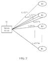
- Fig. 2 illustrates a schematic diagram of a wireless communication system featuring multiple connections between a mobile device 10 and base stations B1-Bn.
- the wireless communication system may be a LTE-Advanced system (i.e. an evolved universal terrestrial radio access network (E-UTRAN)) or any other similar network system.
- the mobile device 10 can operate with carrier aggregation.
- the mobile device 10 communicates with the base stations B1-Bn through radio links L 1 -L m that correspond to component carriers cc#1-cc#m configured in the mobile device 10 respectively.
- Each of the component carriers cc#1-cc#m corresponds to a radio frequency (RF) channel whose bandwidth may be varied according to different communication systems.
- the mobile device 10 is referred as a user equipment (UE) or a mobile station (MS), and can be a device such as a mobile phone, a computer system, etc.
- UE user equipment
- MS mobile station
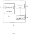
- Fig. 3 illustrates a schematic diagram of an exemplary communication device 20.
- the communication device 20 can be the mobile device 10 shown in Fig. 1 , but is not limited herein.
- the communication device 20 may include a processing means 200 such as a microprocessor or Application Specific Integrated Circuit (ASIC), a storage unit 210 and a communication interfacing unit 220.
- the storage unit 210 may be any data storage device that can store program code 214, for access by the processing means 200. Examples of the storage unit 210 include but are not limited to a subscriber identity module (SIM), read-only memory (ROM), flash memory, random-access memory (RAM), CD-ROMs, magnetic tape, hard disk, and optical data storage device.
- SIM subscriber identity module
- ROM read-only memory
- RAM random-access memory
- CD-ROMs magnetic tape
- hard disk hard disk
- optical data storage device optical data storage device.
- the communication interfacing unit 220 is preferably a radio transceiver and can exchange wireless signals with the network according to processing
- Fig. 4 illustrates a schematic diagram of communication protocol layers for the LTE system.
- the behaviors of some of the protocol layers may be defined in the program code 214 and executed by the processing means 200.
- the protocol layers from top to bottom are a radio resource control (RRC) layer 300, a packet data convergence protocol (PDCP) layer 310, a radio link control (RLC) layer 320, a medium access control (MAC) layer 330 and a physical (PHY) layer 340.
- RRC radio resource control
- PDCP packet data convergence protocol
- RLC radio link control
- MAC medium access control
- PHY physical
- the MAC layer 330 may generate a MAC PDU (Protocol Data Unit) for buffer status reporting (BSR).
- BSR buffer status reporting
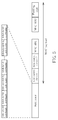
- Fig. 5 illustrates a schematic diagram of a formation of a MAC PDU.
- the MAC PDU includes at least a MAC subheader and at least a BSR MAC control element for indicating a buffer size of a logical channel group in the UE. Note that, Even though multiple events trigger the BSR procedure, the MAC PDU may not need to send multiple reports with the same status or size. Moreover, when the buffer status report is included in the MAC PDU for transmission, all triggered BSR may be cancelled.
- the UE may request for the uplink resource via scheduling request (SR) procedure for MAC PDU transmission.
- SR scheduling request
- the UE may not report the buffer status report if the uplink grant could accommodate all pending data available for transmission.
- the eNB may determine to add/remove a (uplink) component carrier, activate/deactivate a (uplink) component carrier, perform handover procedure due to heavy loading, and/or perform primary component carrier (PCC) change procedure for load balance.
- PCC primary component carrier
- Fig. 6 illustrates a flowchart of an exemplary process 60.
- the process 60 is utilized in a UE (as the mobile device 10 of Fig. 2 ) capable of UL MIMO and/or capable of communicating with the network through a plurality of component carriers, for performing buffer status reporting.
- the process 60 can be compiled into the program code 214 and includes the following steps:
- the UE generates one MAC subheader corresponding to at least two MAC control elements for jointly indicating buffer status of the logical channel group(s), or generates at least two MAC subheader corresponding to the at least two MAC control elements for jointly indicating buffer status of the logical channel group(s).
- the UE utilizes two or more MAC control elements for indicating the buffer size of the logical channel group(s), so as to increase the buffer size indication range.
- the UE is configured a number of "m" component carriers, and thereby the size of data that is buffered in a logical channel group for transmitting on the "m" component carriers may not be accurately indicated by the conventional 6-bit buffer size table.
- the detailed description can be referred from above, so it is not given herein.
- the UE uses at least two MAC control elements for jointly indicating the buffer size of at least a logical channel group.
- the UE used only one MAC control element to indicate buffer size of at least a logical channel group, which may cause insufficient resource allocation.
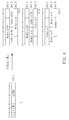
- Fig. 7 illustrates a schematic diagram of multiple MAC control elements for buffer size indication.
- two long BSR MAC control elements with 6-bit index field are applied to indicate buffer status of logical channel groups LCGO-LCG3.
- a sufficient resource can be allocated by the network since accurate buffer size range is known.
- Fig. 8 three long BSR MAC control elements CE1-CE3 are applied to indicate buffer status of glacial channel groups LCGO-LCG3, and correspond to one MAC subheader.
- the MAC subheader includes information of a number of the corresponding BSR MAC control elements, and thereby the network knows how many BSR MAC control elements are used for jointly indicating the buffer status of the logical channel groups.
- two R-bits in MAC subheader is used for indicating the number of the BSR MAC control element.
- the '00' represents one MAC control element
- '01' represents two MAC control elements
- '10' represents three MAC control elements
- '11' represents four MAC control elements.
- LCID value and two R bits are combined to indicate the number of the MAC control elements. For example, one LCID (e.g. 00001) for one, two, three and four MAC control elements, and another LCID (e.g. 10000) for one, two, four and eight MAC control elements.
- the MAC subheader and/or the corresponding MAC control element(s) may further include at least one of the following information:
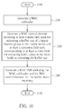
- Fig. 10 illustrates a flowchart of an exemplary process 100.
- the process 100 is utilized in a UE (as the mobile device 10 of Fig. 2 ) capable of UL MIMO and/or capable of communicating with the network through a plurality of component carriers, for performing buffer status reporting.
- the process 100 can be compiled into the program code 214 and includes the following steps:
- At least a extension field corresponding to the at least a index field is included in the MAC control element for extending buffer size indication range and index value range, so as to accurately indicate the buffer size of the logical channel group to the network.
- the MAC control element size is extended (e.g. adding one or two bytes in the end of the MAC control element) for extending buffer size indication range and index value.
- Fig. 11 illustrates a schematic diagram of a MAC control element for buffer size indication.
- the conventional 6-bit buffer size table in Fig. 1 is used.
- the extension field is 2 bits, and is used for indicating the number of the maximum buffer size value (e.g. 150000 bytes) is added per buffer. For example, suppose '00' represents 0, '01' represents 1, '10' represents 2, and '11' represents 3.
- the extension field may be 4 bits for indicating the number of the maximum buffer size value is added per buffer. For example, suppose '0000' represents 0, '0001' represents 1, '0010' represents 2, and so on.
- the operation of buffer size range extension can be referred from above, so it is omitted herein.
- the MAC subheader and/or the corresponding MAC control element(s) may include at least one of the following information:
- Fig. 12 illustrates a flowchart of an exemplary process 120.
- the process 120 is utilized in a UE (as the mobile device 10 of Fig. 2 ) capable of capable of UL MIMO and/or communicating with the network through a plurality of component carriers, for performing buffer status reporting.
- the process 120 can be compiled into the program code 214 and includes the following steps:
- At least a MAC control element including extension fields is used for extending buffer size indication range or index value range, so as to accurately indicate the buffer size of the logical channel group to the network.
- an extension MAC control element including no index field but extension fields is introduced for extending buffer size indication range or index value.
- Fig. 13 illustrates a schematic diagram of a MAC control element for buffer size indication.
- the conventional 6-bit buffer size table in Fig. 1 is used.
- the extension field in MAC control element CE2 is 2 bits, and is used for indicating the number of the maximum buffer size value (e.g. 150000 bytes) is added per buffer.
- '00' represents 0, '01' represents 1, '10' represents 2, and '11' represents 3.
- the extension field may be 4 bits for indicating the number of the maximum buffer size value is added per buffer. Suppose '0000' represents 0, '0001' represents 1, '0010' represents 2, and so on. The operation of buffer size range extension can be referred from above, so it is omitted herein.
- the MAC control elements CE1-CE2 correspond to MAC subheaders S1-S2 respectively, and these two MAC subheaders S1-S2 may use different LCID for indicating a format of the MAC control element CE1-CE2 (e.g. long, short, and/or extended MAC control element). For example, a first LCID in the MAC subheader S1 indicates that the MAC control element CE1 is a long format MAC control element, and a second LCID in the MAC subheader S2 indicates that the MAC control element CE2 is the extension MAC control element.
- a first LCID in the MAC subheader S1 indicates that the MAC control element CE1 is a long format MAC control element
- a second LCID in the MAC subheader S2 indicates that the MAC control element CE2 is the extension MAC control element.
- index value extension For index value extension, please refer to Fig. 14 .
- the extension field in MAC control element CE2 is 2 bits, which is represent as '00', '01', '10', and '11'.
- the 2 bits of the extension field is jointly encoding with the 6 bits of the index field for extending the index value in the index field. For example, adding the 2 bits of the extension field in the most significant bits or the least significant bits of the index field, so as to extend the index value range.
- more than one buffer size table can be used.
- one buffer size table is the conventional 6-bit buffer size table, and the other is 4-bit extended buffer size table.
- the extension field in MAC control element CE2 is 4 bits, thereby representing a number of 16 index values in the extended buffer size table.
- the network knows that the index field in MAC control element CE1 and the extension field in MAC control element CE2 are used for jointly indicating the buffer status of the logical channel group. The concept can be referred from above, so the detailed description is not given herein.
- extension MAC control elements CE1-CE3 are applied. Assume the extension field in MAC control element CE2-CE3 is 2 bits, thereby each representing a number of 4 index values in the extended buffer size table. Thus, network knows that the corresponding BSR MAC control elements and extension MAC control elements are used for jointly indicating the buffer status of the logical channel group(s).
- extension MAC control element(s) and the common MAC control element may correspond to a MAC subheader or each to a MAC subheader.
- the MAC subheader and/or the corresponding MAC control element(s) may include at least one of the following information:
- the present invention provides methods and apparatus for performing buffer status reporting, so as to accurately report the amount of data available for transmission to the network, thereby obtaining sufficient resource for transmission.
Landscapes
- Engineering & Computer Science (AREA)
- Signal Processing (AREA)
- Computer Networks & Wireless Communication (AREA)
- Mobile Radio Communication Systems (AREA)
Abstract
Description
- The application relates to a method of performing buffer status reporting in a wireless communication system and a related communication device.
- Long Term Evolution wireless communication system (LTE system), an advanced high-speed wireless communication system established upon the 3G mobile telecommunication system, supports only packet-switched transmission, and tends to implement both Medium Access Control (MAC) layer and Radio Link Control (RLC) layer in one single communication site, such as in Node B (NB) alone rather than in NB and RNC (Radio Network Controller) respectively, so that the system structure becomes simple.
- In LTE, MAC provides transmission services via a plurality of logic channels. To manage uplink resources, when a user equipment (UE) performs uplink transmission, the network can divide or map logical channels of the UE into at most four groups based on priorities, types, QoS and so on. The 3rd Generation Partnership Project, 3GPP, introduces a buffer status reporting (BSR) procedure, which is used to provide the network with information about an amount of data in at least an uplink buffer (hereafter called a buffer size) of the UE.
- In the BSR procedure, UE uses a MAC PDU (Protocol Data Unit) to carry a BSR MAC control element for reporting buffer size of one or four logical channel groups of the UE. Accordingly, the network can determine the total amount of data available across one or four logical channel groups, so as to allocate uplink resource to the UE for data transmission. According to different requirements, BSR MAC control element can be categorized into two formats: short and long formats. A short BSR MAC control element is 1-byte long, and has 8 bits, where the former 2 bits (called a logical channel group identity (LCG ID) field) indicate one logical channel group which buffer status is being reported, and the remaining 6 bits (called an index field) indicate an index value. A long BSR control element is three-byte long, and has four index fields indicating four index values at a time.
- More specifically, please refer to
Fig. 1 , which is a schematic diagram of a buffer size table according to the prior art. According to the buffer size table, each index value (e.g. index='0'-'63') corresponds to a buffer size value (e.g. from 0 to 150000 byte) in byte. For example, the index='0' corresponds to BS=0, the index='1' corresponds to 0<BS<=10, and so on. Thus, when the network receives the MAC PDU including the BRS MAC control element, the network knows the buffer status of the logical channel group according to the index value in the index field of the BSR MAC control element and the buffer size table, so as to allocate sufficient resource to the UE. - Moreover, the MAC PDU carries a MAC header consisting of at least a MAC subheader. The MAC subheader corresponding to the BSR MAC control element generally consists of two Reserved bits, an 1-bit Extension field and a 5-bit logic channel identity (LCID) field. In the current specification, the format (e.g. the short BSR MAC control element or long BSR MAC control element) of the BSR MAC control element can be identified by a LCID value in the LCID field.
- A long term evolution-advanced (LTE-A) system, as its name implies, is an evolution of the LTE system. The LTE-A system targets faster switching between power states, improves performance at a cell edge, and includes subjects, such as bandwidth extension, coordinated multipoint transmission/reception (CoMP), UL multiple-input multiple-output (MIMO), etc.
- For bandwidth extension, carrier aggregation is introduced to the LTE-Advanced system for extension to wider bandwidth, where two or more component carriers are aggregated, for supporting wider transmission bandwidths (for example up to 100MHz) and for spectrum aggregation. According to carrier aggregation capability, multiple component carriers are aggregated into overall wider bandwidth, where the UE can establish multiple links corresponding to the multiple component carriers for simultaneously receiving and/or transmitting.
- In the LTE system, the buffer size table of
Fig. 1 is defined for the UE supporting a single component carrier. For the UE supporting only one component carrier, the maximum buffer size value (e.g. 150000 bytes) corresponding to the maximum index value (e.g. index='63') is sufficient for buffer status reporting. However, in the LTE-Advanced system, the UE is allowed to transmit/receive data on multiple component carriers to increase the data rate. Thus, the maximum buffer size value is not enough for buffer status reporting in multiple component carriers, causing the network to allocate insufficient resources to the UE for data transmission. For example, there are 200000 bytes in an uplink buffer for transmission. The UE sends a MAC PDU including a BSR MAC control element to the network (i.e. an eNB) for buffer status reporting. However, the BSR MAC control element indicates index='63' to the eNB, and thereby the eNB may think there are only 150000 bytes for uplink transmission. Thus, the eNB may allocate insufficient resources to the UE. - In addition, an extended buffer size table (e.g. 8-bit, or 10-bit buffer size table) may be introduced in the LTE-Advanced system, for extending the buffer size indication range (e.g. up to 3000000 bytes). However, the method of performing buffer status reporting is never concerted. In other words, method of MAC PDU for buffer status reporting is not clearly defined. For example, due to the conventional format of the BSR MAC control element (e.g. only 6 bits for index value indication), the index value indicated by the BSR MAC control element is up to index='63'. Even though there is an index value in the extended buffer size table larger than index='63', the current BSR MAC control element is unable to indicate the extended index value (e.g. index='255' with 8-bit buffer size table) or extended buffer size value (e.g. 3000000 bytes).
- This in mind, the application aims at providing a method and a communication device of a wireless communication system for performing buffer status reporting to solve the abovementioned problem.
- This is achieved by a method and a communication device performing buffer status reporting according to
claims - As will be seen more clearly from the detailed description following below, the claimed method of performing buffer status reporting for a mobile device capable of UL MIMO and/or capable of receiving and transmitting on a plurality of component carriers in a wireless communication system comprises generating at least a MAC subheader, generating at least two MAC control elements for jointly indicating buffer status of at least a logical channel group in the mobile device, and generating a MAC PDU including the at least a MAC subheader and the at least two MAC control elements for the buffer status reporting.
-
-
Fig. 1 illustrates a schematic diagram of a buffer size table according the prior art. -
Fig. 2 illustrates a schematic diagram of an exemplary wireless communication system. -
Fig. 3 illustrates a schematic diagram of an exemplary communication device. -
Fig. 4 illustrates a schematic diagram of communication protocol layers for an exemplary communication system. -
Fig. 5 illustrates a schematic diagram of a formation of a MAC PDU. -
Fig. 6 is a flowchart of an exemplary process. -
Fig. 7-Fig. 9 illustrate schematic diagrams of multiple MAC control elements for buffer size indication. -
Fig. 10 is a flowchart of an exemplary process. -
Fig. 11 illustrates a schematic diagram of a MAC control element for buffer size indication. -
Fig. 12 is a flowchart of an exemplary process. -
Fig. 13-Fig. 15 illustrate schematic diagrams of multiple MAC control elements for buffer size indication. - Please refer to
Fig. 2 , which illustrates a schematic diagram of a wireless communication system featuring multiple connections between amobile device 10 and base stations B1-Bn. The wireless communication system may be a LTE-Advanced system (i.e. an evolved universal terrestrial radio access network (E-UTRAN)) or any other similar network system. Themobile device 10 can operate with carrier aggregation. InFig. 2 , themobile device 10 communicates with the base stations B1-Bn through radio links L1-Lm that correspond to component carriers cc#1-cc#m configured in themobile device 10 respectively. Each of the component carriers cc#1-cc#m corresponds to a radio frequency (RF) channel whose bandwidth may be varied according to different communication systems. In addition, themobile device 10 is referred as a user equipment (UE) or a mobile station (MS), and can be a device such as a mobile phone, a computer system, etc. -
Fig. 3 illustrates a schematic diagram of anexemplary communication device 20. Thecommunication device 20 can be themobile device 10 shown inFig. 1 , but is not limited herein. Thecommunication device 20 may include a processing means 200 such as a microprocessor or Application Specific Integrated Circuit (ASIC), astorage unit 210 and acommunication interfacing unit 220. Thestorage unit 210 may be any data storage device that can storeprogram code 214, for access by the processing means 200. Examples of thestorage unit 210 include but are not limited to a subscriber identity module (SIM), read-only memory (ROM), flash memory, random-access memory (RAM), CD-ROMs, magnetic tape, hard disk, and optical data storage device. Thecommunication interfacing unit 220 is preferably a radio transceiver and can exchange wireless signals with the network according to processing results of the processing means 200. - Please refer to
Fig. 4 , which illustrates a schematic diagram of communication protocol layers for the LTE system. The behaviors of some of the protocol layers may be defined in theprogram code 214 and executed by the processing means 200. The protocol layers from top to bottom are a radio resource control (RRC)layer 300, a packet data convergence protocol (PDCP)layer 310, a radio link control (RLC)layer 320, a medium access control (MAC)layer 330 and a physical (PHY)layer 340. - The
MAC layer 330 may generate a MAC PDU (Protocol Data Unit) for buffer status reporting (BSR). Please refer toFig. 5 , which illustrates a schematic diagram of a formation of a MAC PDU. The MAC PDU includes at least a MAC subheader and at least a BSR MAC control element for indicating a buffer size of a logical channel group in the UE. Note that, Even though multiple events trigger the BSR procedure, the MAC PDU may not need to send multiple reports with the same status or size. Moreover, when the buffer status report is included in the MAC PDU for transmission, all triggered BSR may be cancelled. In addition, if an uplink grant is not configured to the UE, the UE may request for the uplink resource via scheduling request (SR) procedure for MAC PDU transmission. Note that, in some cases, the UE may not report the buffer status report if the uplink grant could accommodate all pending data available for transmission. After the UE sends the MAC PDU including the buffer status report to the network (i.e. an eNB), the eNB may determine to add/remove a (uplink) component carrier, activate/deactivate a (uplink) component carrier, perform handover procedure due to heavy loading, and/or perform primary component carrier (PCC) change procedure for load balance. - Please refer to
Fig. 6 , which illustrates a flowchart of anexemplary process 60. Theprocess 60 is utilized in a UE (as themobile device 10 ofFig. 2 ) capable of UL MIMO and/or capable of communicating with the network through a plurality of component carriers, for performing buffer status reporting. Theprocess 60 can be compiled into theprogram code 214 and includes the following steps: - Step 600: Start.
- Step 610: Generate at least a MAC subheader.
- Step 620: Generate at least two MAC control elements for jointly indicating buffer status of at least a logical channel group in the mobile device.
- Step 630: Generate a MAC PDU including the at least a MAC subheader and the at least two MAC control elements for the buffer status reporting.
- Step 640: End.
- According to the
process 60, the UE generates one MAC subheader corresponding to at least two MAC control elements for jointly indicating buffer status of the logical channel group(s), or generates at least two MAC subheader corresponding to the at least two MAC control elements for jointly indicating buffer status of the logical channel group(s). In a word, the UE utilizes two or more MAC control elements for indicating the buffer size of the logical channel group(s), so as to increase the buffer size indication range. - Take an example based on the
process 60. Referring back toFig. 2 , the UE is configured a number of "m" component carriers, and thereby the size of data that is buffered in a logical channel group for transmitting on the "m" component carriers may not be accurately indicated by the conventional 6-bit buffer size table. The detailed description can be referred from above, so it is not given herein. In this situation, the UE uses at least two MAC control elements for jointly indicating the buffer size of at least a logical channel group. Compared to the prior art, the UE used only one MAC control element to indicate buffer size of at least a logical channel group, which may cause insufficient resource allocation. - Please refer to
Fig. 7 , which illustrates a schematic diagram of multiple MAC control elements for buffer size indication. InFig. 7 , two long BSR MAC control elements with 6-bit index field are applied to indicate buffer status of logical channel groups LCGO-LCG3. The index='2' and index='4', index='34' and index='23', index='63' and index='28', and index='56' and index='17' are paired for buffer size indication. For example, the index='63' and index='28' correspond to BS>150000 and 603<BS<=706. For indicating a buffer status of the logical channel group LCG2, the buffer size values corresponding to the index='63' and index='28' are added to form a newbuffer size range 150000+603<BS<=150000+706 (150603<BS<=150706). Thus, a sufficient resource can be allocated by the network since accurate buffer size range is known. - In
Fig. 8 , three long BSR MAC control elements CE1-CE3 are applied to indicate buffer status of glacial channel groups LCGO-LCG3, and correspond to one MAC subheader. A buffer size of the logical channel group LCG0 is indicated by index='63' in MAC control element CE1, index='63' MAC control element CE2, and index='2' in MAC control element CE3. The buffer size range is 150000+150000+10<BS<=150000+150000+12. The concept can be referred from above, so the detail is omitted herein. Note that, the MAC subheader includes information of a number of the corresponding BSR MAC control elements, and thereby the network knows how many BSR MAC control elements are used for jointly indicating the buffer status of the logical channel groups. In order to realize this, two R-bits in MAC subheader is used for indicating the number of the BSR MAC control element. For example, the '00' represents one MAC control element, '01' represents two MAC control elements, '10' represents three MAC control elements, and '11' represents four MAC control elements. Moreover, LCID value and two R bits are combined to indicate the number of the MAC control elements. For example, one LCID (e.g. 00001) for one, two, three and four MAC control elements, and another LCID (e.g. 10000) for one, two, four and eight MAC control elements. - On the other hand, in
Fig. 9 , each BSR MAC control element corresponds to a MAC subheader. That is, the number of the MAC subheader is the same as the number of the BSR MAC control element. Note that, the three MAC subheaders may have the same LCID, so the network knows that the corresponding BSR MAC control elements are used for jointly indicating the buffer status of the logical channel groups. For example, a buffer size of the logical channel group LCG2 is indicated according to buffer size value indicated by index='63' in MAC control element CE1, index='32' in MAC control element CE2, and index='0' in MAC control element CE3. The buffer size range is 150000+1132+0<BS<=150000+1326+0. The concept can be referred from above, so the detailed description is not given herein. - Besides, the MAC subheader and/or the corresponding MAC control element(s) may further include at least one of the following information:
- 1. Logical channel group identity (LCG ID), for identifying the logical channel group(s) whose buffer status is reported.
- 2. Buffer size table indication, for indicating the used buffer size table. For example, two or more buffer size tables may be used by the UE for buffer status report, and the two R-bits may be set to '00', '01', '10', '11' for representing 4 types of buffer size table.
- 3. Component carrier configuration, for adding/removing, or activate/deactivate a component carrier. For example, an indicator may be used to indicate whether the buffer status for at least one LCG exceeds a pre-defined threshold, and/or to indicate whether the sum of buffer status for at least one LCG exceeds a pre-defined threshold. Thus, the network may determine whether to add/remove or activate/deactivate a component carrier based on the indicator.
- 4. Length field, for indicating length or bytes of the corresponding MAC control elements.
- 5. Logical channel identity (LCID), for indicating a format of the corresponding MAC control element (e.g. long or short MAC control element).
- 6. Number of MAC control elements, for indicating a number of the corresponding BSR MAC control elements used jointly to report the buffer status of the logical channel group(s).
- Please refer to
Fig. 10 , which illustrates a flowchart of an exemplary process 100. The process 100 is utilized in a UE (as themobile device 10 ofFig. 2 ) capable of UL MIMO and/or capable of communicating with the network through a plurality of component carriers, for performing buffer status reporting. The process 100 can be compiled into theprogram code 214 and includes the following steps: - Step 1000: Start.
- Step 1010: Generate a MAC subheader.
- Step 1020: Generate a MAC control element including at least a index field each for indicating a buffer size of a logical channel group in the mobile device and at least a extension field each corresponding to at least a index field for extending index values in the index fields or extending the buffer size.
- Step 1030: Generate a MAC PDU including the MAC subheader and the MAC control element, for the buffer status reporting.
- Step 1040: End.
- According to the process 100, at least a extension field corresponding to the at least a index field is included in the MAC control element for extending buffer size indication range and index value range, so as to accurately indicate the buffer size of the logical channel group to the network. In a word, the MAC control element size is extended (e.g. adding one or two bytes in the end of the MAC control element) for extending buffer size indication range and index value.
- Please refer to
Fig. 11 , which illustrates a schematic diagram of a MAC control element for buffer size indication. In an embodiment, the conventional 6-bit buffer size table inFig. 1 is used. Assume the extension field is 2 bits, and is used for indicating the number of the maximum buffer size value (e.g. 150000 bytes) is added per buffer. For example, suppose '00' represents 0, '01' represents 1, '10' represents 2, and '11' represents 3. Thus, the buffer size of the logical channel group LCG0 is that the maximum buffer size value added twice pluses a buffer size value corresponding to the index='2'. That is, the buffer size range is 150000+150000+10<BS<=150000+150000+12. On the other hand, the extension field may be 4 bits for indicating the number of the maximum buffer size value is added per buffer. For example, suppose '0000' represents 0, '0001' represents 1, '0010' represents 2, and so on. The operation of buffer size range extension can be referred from above, so it is omitted herein. - Note that, the MAC subheader and/or the corresponding MAC control element(s) may include at least one of the following information:
- 1. Logical channel group identity (LCG ID), for identifying the logical channel group(s) whose buffer status is reported.
- 2. Buffer size table indication, for indicating the used buffer size table.
- 3. Component carrier configuration, for adding/removing, or activate/deactivate a component carrier. For example, an indicator may be used to indicate whether the buffer status for at least one LCG exceeds a pre-defined threshold, and/or to indicate whether the sum of buffer status for at least one LCG exceeds a pre-defined threshold. Thus, the network may determine whether to add/remove or activate/deactivate a component carrier based on the indicator.
- 4. Length field, for indicating length or bytes of the corresponding MAC control elements.
- 5. Logical channel identity (LCID), for indicating a format of the corresponding MAC control element (e.g. long, short, and/or extended MAC control element).
- 6. Number of MAC control elements, for indicating a number of the corresponding BSR MAC control elements used jointly to report the buffer status of the logical channel group(s).
- Please refer to
Fig. 12 , which illustrates a flowchart of an exemplary process 120. The process 120 is utilized in a UE (as themobile device 10 ofFig. 2 ) capable of capable of UL MIMO and/or communicating with the network through a plurality of component carriers, for performing buffer status reporting. The process 120 can be compiled into theprogram code 214 and includes the following steps: - Step 1200: Start.
- Step 1210: Generate at least a MAC subheader.
- Step 1220: Generate a first MAC control element including at least a index field each for indicating a buffer size of a logical channel group in the mobile device and at least a second MAC control element each including at least a extension field corresponding to the at least a index field for extending index values in the index fields or extending the buffer sizes.
- Step 1230: Generate a MAC PDU including the first MAC subheader and the at least a second MAC control element, for the buffer status reporting.
- Step 1240: End.
- According to the process 120, at least a MAC control element including extension fields is used for extending buffer size indication range or index value range, so as to accurately indicate the buffer size of the logical channel group to the network. In a word, an extension MAC control element including no index field but extension fields is introduced for extending buffer size indication range or index value.
- Please refer to
Fig. 13 , which illustrates a schematic diagram of a MAC control element for buffer size indication. In an embodiment, the conventional 6-bit buffer size table inFig. 1 is used. Assume the extension field in MAC control element CE2 is 2 bits, and is used for indicating the number of the maximum buffer size value (e.g. 150000 bytes) is added per buffer. Suppose '00' represents 0, '01' represents 1, '10' represents 2, and '11' represents 3. Thus, the buffer size of the logical channel group LCG0 is that the maximum buffer size value added twice pluses a buffer size value corresponding to the index='2' in MAC control element CE1. That is, the buffer size range is 150000+150000+10<BS<=150000+150000+12. On the other hand, the extension field may be 4 bits for indicating the number of the maximum buffer size value is added per buffer. Suppose '0000' represents 0, '0001' represents 1, '0010' represents 2, and so on. The operation of buffer size range extension can be referred from above, so it is omitted herein. - Note that, the MAC control elements CE1-CE2 correspond to MAC subheaders S1-S2 respectively, and these two MAC subheaders S1-S2 may use different LCID for indicating a format of the MAC control element CE1-CE2 (e.g. long, short, and/or extended MAC control element). For example, a first LCID in the MAC subheader S1 indicates that the MAC control element CE1 is a long format MAC control element, and a second LCID in the MAC subheader S2 indicates that the MAC control element CE2 is the extension MAC control element.
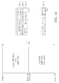
- For index value extension, please refer to
Fig. 14 . In this embodiment, an extended 8-bit buffer size table is used. The extended buffer size table includes index value from 0 to 255 (i.e. index='0'-'255'). Assume the extension field in MAC control element CE2 is 2 bits, which is represent as '00', '01', '10', and '11'. The 2 bits of the extension field is jointly encoding with the 6 bits of the index field for extending the index value in the index field. For example, adding the 2 bits of the extension field in the most significant bits or the least significant bits of the index field, so as to extend the index value range. Thus, each of the index='0'-'255' can be indicated by the MAC control elements CE1-CE2. - In another embodiment, more than one buffer size table can be used. As illustrated in
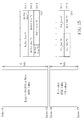
Fig. 15 , one buffer size table is the conventional 6-bit buffer size table, and the other is 4-bit extended buffer size table. The extension field in MAC control element CE2 is 4 bits, thereby representing a number of 16 index values in the extended buffer size table. The network knows that the index field in MAC control element CE1 and the extension field in MAC control element CE2 are used for jointly indicating the buffer status of the logical channel group. The concept can be referred from above, so the detailed description is not given herein. - On the other hand, more than one extension MAC control elements CE1-CE3 is applied. Assume the extension field in MAC control element CE2-CE3 is 2 bits, thereby each representing a number of 4 index values in the extended buffer size table. Thus, network knows that the corresponding BSR MAC control elements and extension MAC control elements are used for jointly indicating the buffer status of the logical channel group(s).
- Note that, the extension MAC control element(s) and the common MAC control element may correspond to a MAC subheader or each to a MAC subheader. In addition, the MAC subheader and/or the corresponding MAC control element(s) may include at least one of the following information:
- 1. Logical channel group identity (LCG ID), for identifying the logical channel group(s) whose buffer status is reported.
- 2. Buffer size table indication, for indicating the used buffer size table (e.g. the 6-bit, 8-bit, or 10-bit buffer size table).
- 3. Component carrier configuration, for adding/removing, or activate/deactivate a component carrier. For example, an indicator may be used to indicate whether the buffer status for at least one LCG exceeds a pre-defined threshold, and/or to indicate whether the sum of buffer status for at least one LCG exceeds a pre-defined threshold. Thus, the network may determine whether to add/remove or activate/deactivate a component carrier based on the indicator.
- 4. Length field, for indicating length or bytes of the corresponding MAC control elements.
- 5. Logical channel identity (LCID), for indicating a format of the corresponding MAC control element (e.g. long, short, and/or extension MAC control element).
- 6. Number of MAC control elements, for indicating a number of the corresponding BSR MAC control elements used jointly to report the buffer status of the logical channel group(s).
- In conclusion, the present invention provides methods and apparatus for performing buffer status reporting, so as to accurately report the amount of data available for transmission to the network, thereby obtaining sufficient resource for transmission.
Claims (24)
- A method of performing buffer status reporting for a mobile device capable of uplink multiple-input multiple-output, hereafter called MIMO, and/or capable of receiving and transmitting on a plurality of component carriers in a wireless communication system, characterized by the method comprising:generating at least a medium access control, hereafter called MAC, subheader;generating at least two MAC control elements for jointly indicating buffer status of at least a logical channel group in the mobile device; andgenerating a MAC protocol data unit including the at least a MAC subheader and the at least two MAC control elements for the buffer status reporting.
- The method of claim 1, characterized in that the MAC control element is in a short format for which buffer status of one logical channel group is reported, or in a long format for which buffer status of all logical channel groups are reported; and the MAC control element includes information of at least a index field in a buffer size table in the mobile device for indicating the at least a buffer size of the at least a logical channel group.
- The method of claim 2, characterized in that generating at least two MAC control elements for jointly indicating the buffer status of the at least a logical channel group in the mobile device comprises:generating the at least two MAC control elements for jointly indicating the buffer status of the at least a logical channel group in the mobile device via adding the at least a buffer size indicated by the at least a index field in the buffer size table.
- The method of claim 2, characterized in that the MAC subheader and/or MAC control element includes information of at least one of a logical channel identity for indicating the format of the MAC control element, a logical channel group identity for indicating the buffer status of which logical channel group is reported, a buffer size table indication associated to a buffer size table used in the buffer status report, a component carrier configuration for adding/removing, or activating/deactivating a component carrier of the plurality of component carriers, a number of the MAC control elements for the buffer status reporting, a length of the corresponding MAC control elements.
- A method of performing buffer status reporting for a mobile device capable of uplink multiple-input multiple-output, hereafter called MIMO, and/or capable of receiving and transmitting on a plurality of component carriers in a wireless communication system, characterized by the method comprising:generating a medium access control, hereafter called MAC, subheader;generating a MAC control element including at least a index field each for indicating a buffer size of a logical channel group in the mobile device and at least a extension field each corresponding to at least a index field for extending index values in the index fields or extending the buffer size; andgenerating a MAC protocol data unit including the MAC subheader and the MAC control element, for the buffer status reporting.
- The method of claim 5, characterized in that the MAC control element is in a short format for which one buffer status of one logical channel group is reported, or in a long format for which buffer status of all logical channel groups are reported.
- The method of claim 6, characterized in that the MAC subheader and/or MAC control element includes information of at least one of a logical channel identity for indicating the format of the MAC control element, a logical channel group identity for indicating the buffer status of which logical channel group is reported, a buffer size table indication associated to a buffer size table used in the buffer status report, a component carrier configuration for adding/removing, or activating/deactivating a component carrier of the plurality of component carriers, a length of the corresponding MAC control element, a number of the MAC control elements for the buffer status reporting.
- The method of claim 5, characterized in that generating the MAC control element including the at least a index field each for indicating the buffer size of the logical channel group in the mobile device and the at least a extension field each corresponding to at least a index field for extending index values in the index fields or extending the buffer size comprises:generating the MAC control element including the at least a index field and the at least a extension field each corresponding to at least a index field for extending index values in the index fields or extending the buffer size via adding a number indicated in the extension field with the buffer size indicated in the index field.
- A method of performing buffer status reporting for a mobile device capable of uplink multiple-input multiple-output, hereafter called MIMO, and/or capable of receiving and transmitting on a plurality of component carriers in a wireless communication system, characterized by the method comprising:generating at least a medium access control, hereafter called MAC, subheader;generating a first MAC control element including at least a index field each for indicating a buffer size of a logical channel group in the mobile device and at least a second MAC control element each including at least a extension field corresponding to the at least a index field for extending index values in the index fields or extending the buffer sizes; andgenerating a MAC protocol data unit including the first MAC subheader and the at least a second MAC control element, for the buffer status reporting.
- The method of claim 9, characterized in that the first MAC control element is in a short format for which one buffer status of one logical channel group is reported, or in a long format for which buffer status of all logical channel groups are reported.
- The method of claim 10, characterized in that the MAC subheader and/or the first MAC control element includes information of at least one of a logical channel identity for indicating the format of the MAC control element, a logical channel group identity for indicating the buffer status of which logical channel group is reported, a buffer size table indication associated to a buffer size table used in the buffer status report, a component carrier configuration for adding/removing, or activating/deactivating a component carrier of the plurality of component carriers, a length of the corresponding MAC control element, and a number of MAC control elements for the buffer status reporting.
- The method of claim 9, characterized in that generating the first MAC control element including the at least a index field each for indicating the buffer size of the logical channel group in the mobile device and the at least a second MAC control element each including the at least a extension field corresponding to the at least a index field for extending index values in the index fields or extending the buffer sizes comprises:generating the first MAC control element and the at least a second MAC control element for extending the index values in the index fields via adding bits of the extension field in the most significant bits or the least significant bits of the index field;generating the first MAC control element and the at least a second MAC control element for extending the index values in the index fields via adding index values indicated by the extension fields of the second MAC control element with the index values in the index fields of the first MAC control element; orgenerating the first MAC control element and the at least a second MAC control element for extending the index values in the index fields via adding buffer size values indicated by the extension fields of the second MAC control element with the buffer size values indicated by the index fields of the first MAC control element.
- A communication device of a wireless communication system for performing buffer status reporting, the communication device capable of uplink multiple-input multiple-output, hereafter called MIMO, and/or capable of receiving and/or transmitting on a plurality of component carriers and characterized by comprising:means for generating at least a medium access control, hereafter called MAC, subheader;means for generating at least two MAC control elements for jointly indicating buffer status of at least a logical channel group in the mobile device; andmeans for generating a MAC protocol data unit including the at least a MAC subheader and the at least two MAC control elements for the buffer status reporting.
- The communication device of claim 13, characterized in that the MAC control element is in a short format for which buffer status of one logical channel group is reported, or in a long format for which buffer status of all logical channel groups are reported; and the MAC control element includes information of at least a index field in a buffer size table in the mobile device for indicating the at least a buffer size of the at least a logical channel group.
- The communication device of claim 14, characterized in that the means for generating at least two MAC control elements for jointly indicating the buffer status of the at least a logical channel group in the mobile device comprises:means for generating the at least two MAC control elements for jointly indicating the buffer status of the at least a logical channel group in the mobile device via adding the at least a buffer size indicated by the at least a index field in the buffer size table.
- The communication device of claim 14, characterized in that the MAC subheader and/or MAC control element includes information of at least one of a logical channel identity for indicating the format of the MAC control element, a logical channel group identity for indicating the buffer status of which logical channel group is reported, a buffer size table indication associated to a buffer size table used in the buffer status report, a component carrier configuration for adding/removing, or activating/deactivating a component carrier of the plurality of component carriers, a number of the MAC control elements for the buffer status reporting, a length of the corresponding MAC control elements.
- A communication device of a wireless communication system for performing buffer status reporting, the communication device capable of uplink multiple-input multiple-output, hereafter called MIMO, and/or capable of receiving and/or transmitting on a plurality of component carriers and characterized by comprising:means for generating a medium access control, hereafter called MAC, subheader;means for generating a MAC control element including at least a index field each for indicating a buffer size of a logical channel group in the mobile device and at least a extension field each corresponding to at least a index field for extending index values in the index fields or extending the buffer size; andmeans for generating a MAC protocol data unit including the MAC subheader and the MAC control element, for the buffer status reporting.
- The communication device of claim 17, characterized in that the MAC control element is in a short format for which one buffer status of one logical channel group is reported, or in a long format for which buffer status of all logical channel groups are reported.
- The communication device of claim 18, characterized in that the MAC subheader and/or MAC control element includes information of at least one of a logical channel identity for indicating the format of the MAC control element, a logical channel group identity for indicating the buffer status of which logical channel group is reported, a buffer size table indication associated to a buffer size table used in the buffer status report, a component carrier configuration for adding/removing, or activating/deactivating a component carrier of the plurality of component carriers, a length of the corresponding MAC control element, a number of the MAC control elements for the buffer status reporting.
- The communication device of claim 17, characterized in that the means for generating the MAC control element including the at least a index field each for indicating the buffer size of the logical channel group in the mobile device and the at least a extension field each corresponding to at least a index field for extending index values in the index fields or extending the buffer size comprises:means for generating the MAC control element including the at least a index field and the at least a extension field each corresponding to at least a index field for extending index values in the index fields or extending the buffer size via adding a number indicated in the extension field with the buffer size indicated in the index field.
- A communication device of a wireless communication system for performing buffer status reporting, the communication device capable of uplink multiple-input multiple-output, hereafter called MIMO, and/or capable of receiving and/or transmitting on a plurality of component carriers and characterized by comprising:means for generating at least a medium access control, hereafter called MAC, subheader;means for generating a first MAC control element including at least a index field each for indicating a buffer size of a logical channel group in the mobile device and at least a second MAC control element each including at least a extension field corresponding to the at least a index field for extending index values in the index fields or extending the buffer sizes; andmeans for generating a MAC protocol data unit including the first MAC subheader and the at least a second MAC control element, for the buffer status reporting.
- The communication device of claim 21, characterized in that the first MAC control element is in a short format for which one buffer status of one logical channel group is reported, or in a long format for which buffer status of all logical channel groups are reported.
- The communication device of claim 22, characterized in that the MAC subheader and/or the first MAC control element includes information of at least one of a logical channel identity for indicating the format of the MAC control element, a logical channel group identity for indicating the buffer status of which logical channel group is reported, a buffer size table indication associated to a buffer size table used in the buffer status report, a component carrier configuration for adding/removing, or activating/deactivating a component carrier of the plurality of component carriers, a length of the corresponding MAC control element, and a number of MAC control elements for the buffer status reporting.
- The communication device of claim 21, characterized in that the means for generating the first MAC control element including the at least a index field each for indicating the buffer size of the logical channel group in the mobile device and the at least a second MAC control element each including the at least a extension field corresponding to the at least a index field for extending index values in the index fields or extending the buffer sizes comprises:means for generating the first MAC control element and the at least a second MAC control element for extending the index values in the index fields via adding bits of the extension field in the most significant bits or the least significant bits of the index field;means for generating the first MAC control element and the at least a second MAC control element for extending the index values in the index fields via adding index values indicated by the extension fields of the second MAC control element with the index values in the index fields of the first MAC control element; ormeans for generating the first MAC control element and the at least a second MAC control element for extending the index values in the index fields via adding buffer size values indicated by the extension fields of the second MAC control element with the buffer size values indicated by the index fields of the first MAC control element.
Applications Claiming Priority (2)
| Application Number | Priority Date | Filing Date | Title |
|---|---|---|---|
| US35623710P | 2010-06-18 | 2010-06-18 | |
| US13/163,719 US9258088B2 (en) | 2010-06-18 | 2011-06-19 | Method of performing buffer status reporting and communication device thereof |
Publications (2)
| Publication Number | Publication Date |
|---|---|
| EP2398274A1 true EP2398274A1 (en) | 2011-12-21 |
| EP2398274B1 EP2398274B1 (en) | 2018-04-04 |
Family
ID=44352074
Family Applications (1)
| Application Number | Title | Priority Date | Filing Date |
|---|---|---|---|
| EP11170488.8A Active EP2398274B1 (en) | 2010-06-18 | 2011-06-20 | Method of performing buffer status reporting and communication device thereof |
Country Status (4)
| Country | Link |
|---|---|
| US (1) | US9258088B2 (en) |
| EP (1) | EP2398274B1 (en) |
| CN (1) | CN102364984B (en) |
| TW (1) | TWI488525B (en) |
Cited By (5)
| Publication number | Priority date | Publication date | Assignee | Title |
|---|---|---|---|---|
| WO2014133271A1 (en) * | 2013-02-27 | 2014-09-04 | 주식회사 케이티 | Method for transmitting buffer status report of terminal in small cell environment and device therefor |
| WO2014163319A1 (en) * | 2013-04-05 | 2014-10-09 | 주식회사 팬택 | Method and apparatus for transmitting buffer state report by terminal in wireless communication system |
| KR20150020633A (en) * | 2012-06-04 | 2015-02-26 | 차이나 아카데미 오브 텔레커뮤니케이션즈 테크놀로지 | Buffer state reporting method, system, and device |
| WO2016123438A3 (en) * | 2015-01-30 | 2016-11-03 | Qualcomm Incorporated | Soft buffer management for enhanced carrier aggregation |
| US11832125B2 (en) | 2013-02-27 | 2023-11-28 | Kt Corporation | Method for transmitting buffer status report of terminal in small cell environment and device therefor |
Families Citing this family (24)
| Publication number | Priority date | Publication date | Assignee | Title |
|---|---|---|---|---|
| CN102291771B (en) * | 2010-06-21 | 2015-08-12 | 中兴通讯股份有限公司 | A kind of method and system realizing buffer region state reporting |
| CN102378325B (en) | 2010-08-13 | 2016-03-30 | 索尼公司 | Method and device for activating and deactivating uplink of secondary cell of terminal |
| US10149120B2 (en) * | 2010-11-11 | 2018-12-04 | Telefonaktiebolaget Lm Ericsson (Publ) | Group message based carrier aggregation control |
| US8701152B2 (en) * | 2012-03-11 | 2014-04-15 | Broadcom Corporation | Cross layer coordinated channel bonding |
| KR101896440B1 (en) * | 2012-05-14 | 2018-09-11 | 삼성전자 주식회사 | Method and appratus of handling the buffer status report in mobile communication system using inter-base station-carrier aggregation |
| US20130336295A1 (en) * | 2012-06-19 | 2013-12-19 | Esmael Hejazi Dinan | Packet Transmission in Wireless Networks |
| US9264930B2 (en) * | 2012-11-07 | 2016-02-16 | Qualcomm Incorporated | Buffer status reporting and logical channel prioritization in multiflow operation |
| HK1214433A1 (en) * | 2013-01-10 | 2016-07-22 | 美国博通公司 | Buffer status reporting for dual connection |
| WO2014183664A1 (en) * | 2013-05-17 | 2014-11-20 | Mediatek Singapore Pte. Ltd. | Enhanced mechanism of uplink time alignment maintenance for inter-enb carrier aggregation |
| EP2835925B1 (en) * | 2013-08-09 | 2018-08-08 | Panasonic Intellectual Property Corporation of America | Efficient Status Reporting for UEs in dual connectivity during mobility |
| EP3050382B1 (en) * | 2013-09-27 | 2017-03-01 | Telefonaktiebolaget LM Ericsson (publ) | Wireless device, and methods therein |
| US9924405B2 (en) * | 2013-10-04 | 2018-03-20 | Industrial Technology Research Institute | Method for buffer status report in dual connectivity |
| EP3122131B1 (en) * | 2014-03-20 | 2019-12-11 | Sharp Kabushiki Kaisha | Terminal device, integrated circuit, and wireless communication method |
| US10631194B2 (en) * | 2014-03-21 | 2020-04-21 | Nokia Solutions And Networks Oy | Cross reporting of empty or non-empty buffers in dual connectivity |
| EP3595387B1 (en) * | 2014-05-09 | 2022-03-16 | Huawei Technologies Co., Ltd. | User equipment, base station, and communications method of user equipment and base station |
| US10314035B2 (en) | 2015-01-05 | 2019-06-04 | Apple Inc. | Sub-frame allocation for low power LTE |
| WO2016185896A1 (en) * | 2015-05-15 | 2016-11-24 | 京セラ株式会社 | Wireless terminal, base station, and processor |
| CN106412794B (en) * | 2015-07-21 | 2020-01-07 | 电信科学技术研究院 | A method and device for resource allocation |
| WO2017164668A1 (en) * | 2016-03-24 | 2017-09-28 | Lg Electronics Inc. | Method for transmitting data in a communication system and device therefor |
| KR102291807B1 (en) * | 2017-06-16 | 2021-08-19 | 텔레폰악티에볼라겟엘엠에릭슨(펍) | Method and apparatus related to buffer status reporting in a wireless communication network |
| KR102475870B1 (en) * | 2017-11-10 | 2022-12-08 | 삼성전자주식회사 | Method and apparatus for processing data in wireless communication system |
| GB201812926D0 (en) * | 2018-08-08 | 2018-09-19 | Samsung Electronics Co Ltd | Buffer status reporting |
| WO2022145718A1 (en) * | 2020-12-30 | 2022-07-07 | Lg Electronics Inc. | Method and apparatus for transmitting data unit for voluntary traffic in wireless communication system |
| EP4706316A1 (en) * | 2023-08-10 | 2026-03-11 | Ofinno, LLC | Buffer status reporting |
Family Cites Families (9)
| Publication number | Priority date | Publication date | Assignee | Title |
|---|---|---|---|---|
| KR100689354B1 (en) | 2003-09-02 | 2007-03-02 | 삼성전자주식회사 | Method of providing status information of mobile station in mobile communication system |
| JP4545768B2 (en) | 2007-02-28 | 2010-09-15 | 株式会社エヌ・ティ・ティ・ドコモ | Radio control signal generation method, radio base station apparatus, and mobile station |
| US8165066B2 (en) * | 2008-01-03 | 2012-04-24 | Innovative Sonic Limited | Method and apparatus for performing buffer status reporting |
| EP3048835B1 (en) * | 2008-02-20 | 2020-09-30 | Amazon Technologies, Inc. | Apparatus and method for constructing a data unit that includes a buffer status report |
| CN101547435B (en) | 2008-03-25 | 2010-12-08 | 大唐移动通信设备有限公司 | Method and device for reporting cache status |
| JP4976440B2 (en) * | 2008-05-19 | 2012-07-18 | 創新音▲速▼股▲ふん▼有限公司 | Method and communication device for re-establishing connection |
| US8514793B2 (en) | 2008-10-31 | 2013-08-20 | Interdigital Patent Holdings, Inc. | Method and apparatus for monitoring and processing component carriers |
| EP2244515A1 (en) * | 2009-04-23 | 2010-10-27 | Panasonic Corporation | Logical channel prioritization procedure for generating multiple uplink transport blocks |
| US8625415B2 (en) | 2010-04-02 | 2014-01-07 | Nokia Siemens Networks Oy | Dynamic buffer status report selection for carrier aggregation |
-
2011
- 2011-06-19 US US13/163,719 patent/US9258088B2/en active Active
- 2011-06-20 CN CN201110167521.2A patent/CN102364984B/en active Active
- 2011-06-20 TW TW100121458A patent/TWI488525B/en active
- 2011-06-20 EP EP11170488.8A patent/EP2398274B1/en active Active
Non-Patent Citations (3)
| Title |
|---|
| ALCATEL-LUCENT SHANGHAI BELL ET AL: "BSR reporting in Carrier Aggregation", 3GPP DRAFT; R2-103277, 3RD GENERATION PARTNERSHIP PROJECT (3GPP), MOBILE COMPETENCE CENTRE ; 650, ROUTE DES LUCIOLES ; F-06921 SOPHIA-ANTIPOLIS CEDEX ; FRANCE, vol. RAN WG2, no. Montreal, Canada; 20100510, 15 May 2010 (2010-05-15), XP050423430 * |
| NOKIA SIEMENS NETWORKS ET AL: "BSR for Carrier Aggregation", 3GPP DRAFT; R2-102164 BSR FOR CARRIER AGGREGATION, 3RD GENERATION PARTNERSHIP PROJECT (3GPP), MOBILE COMPETENCE CENTRE ; 650, ROUTE DES LUCIOLES ; F-06921 SOPHIA-ANTIPOLIS CEDEX ; FRANCE, vol. RAN WG2, no. Beijing, china; 20100412, 6 April 2010 (2010-04-06), XP050422579 * |
| NOKIA SIEMENS NETWORKS ET AL: "BSR for Carrier Aggregation", 3GPP DRAFT; R2-102805 BSR FOR CARRIER AGGREGATION, 3RD GENERATION PARTNERSHIP PROJECT (3GPP), MOBILE COMPETENCE CENTRE ; 650, ROUTE DES LUCIOLES ; F-06921 SOPHIA-ANTIPOLIS CEDEX ; FRANCE, vol. RAN WG2, no. Montreal, Canada; 20100510, 4 May 2010 (2010-05-04), XP050423147 * |
Cited By (12)
| Publication number | Priority date | Publication date | Assignee | Title |
|---|---|---|---|---|
| KR20150020633A (en) * | 2012-06-04 | 2015-02-26 | 차이나 아카데미 오브 텔레커뮤니케이션즈 테크놀로지 | Buffer state reporting method, system, and device |
| EP2858447A4 (en) * | 2012-06-04 | 2015-04-29 | China Academy Of Telecomm Tech | METHOD, SYSTEM AND STAMP CONDITION REPORT DEVICE |
| KR101643957B1 (en) * | 2012-06-04 | 2016-07-29 | 차이나 아카데미 오브 텔레커뮤니케이션즈 테크놀로지 | Buffer state reporting method, system, and device |
| US9775064B2 (en) | 2012-06-04 | 2017-09-26 | China Academy Of Telecommunications Technology | Buffer state reporting method, system, and device |
| CN107249197A (en) * | 2012-06-04 | 2017-10-13 | 电信科学技术研究院 | A kind of method of buffer region state reporting, system and equipment |
| CN107249197B (en) * | 2012-06-04 | 2019-12-13 | 电信科学技术研究院 | Method, system and equipment for reporting buffer status |
| WO2014133271A1 (en) * | 2013-02-27 | 2014-09-04 | 주식회사 케이티 | Method for transmitting buffer status report of terminal in small cell environment and device therefor |
| US11832125B2 (en) | 2013-02-27 | 2023-11-28 | Kt Corporation | Method for transmitting buffer status report of terminal in small cell environment and device therefor |
| US12335775B2 (en) | 2013-02-27 | 2025-06-17 | Kt Corporation | Method for transmitting buffer status report of terminal in small cell environment and device therefor |
| WO2014163319A1 (en) * | 2013-04-05 | 2014-10-09 | 주식회사 팬택 | Method and apparatus for transmitting buffer state report by terminal in wireless communication system |
| WO2016123438A3 (en) * | 2015-01-30 | 2016-11-03 | Qualcomm Incorporated | Soft buffer management for enhanced carrier aggregation |
| CN107210895A (en) * | 2015-01-30 | 2017-09-26 | 高通股份有限公司 | Soft buffer management for enhanced carrier aggregation |
Also Published As
| Publication number | Publication date |
|---|---|
| EP2398274B1 (en) | 2018-04-04 |
| CN102364984A (en) | 2012-02-29 |
| CN102364984B (en) | 2015-05-20 |
| TWI488525B (en) | 2015-06-11 |
| US9258088B2 (en) | 2016-02-09 |
| US20110310937A1 (en) | 2011-12-22 |
| TW201204143A (en) | 2012-01-16 |
Similar Documents
| Publication | Publication Date | Title |
|---|---|---|
| EP2398274B1 (en) | Method of performing buffer status reporting and communication device thereof | |
| EP2398273B1 (en) | Method of handling buffer status report and communication device thereof | |
| US10674512B2 (en) | Method and apparatus for transmitting and receiving UE capability information mobile communication system | |
| US10511994B2 (en) | Methods for configuring buffer status report for next-generation mobile communication and apparatuses thereof | |
| US10574402B2 (en) | Station (STA), access point (AP) and method for aggregation of data packets for uplink transmission | |
| US10425921B2 (en) | Method of uplink control information transmission | |
| EP2554002B1 (en) | Dynamic buffer status report selection for carrier aggregation | |
| US9839043B2 (en) | Apparatus and method for allocating resources for logical channels in wireless communication system | |
| KR101425959B1 (en) | Assignment of component carriers | |
| US20100272045A1 (en) | Method for allocating uplink resources to logical channels in a wireless communication system and related communication device | |
| US20110317777A1 (en) | Controlling Transmissions on Composite Carriers | |
| EP3110056A1 (en) | Method of handling csi report in multicarriers or comp communication systems and related communication device | |
| US20160066328A1 (en) | Scheduling method, user equipment, and base station | |
| US20130094455A1 (en) | Dynamic Buffer Status Report Selection for Carrier Aggregation | |
| EP3565290A1 (en) | Method and apparatus for transmitting and receiving ue capability information in mobile communication system | |
| EP3621340B1 (en) | Transmission of channel quality information | |
| US12004228B2 (en) | Information transmission method, terminal device, and network device | |
| KR102023672B1 (en) | Methods for configurationing a buffer status report for next-generation mobile communication And Apparatuses thereof | |
| CN102281645A (en) | Method of handling semi-persistent scheduling transmission and related communication device | |
| CN102377539A (en) | Methods for feedback and acquisition of channel state information (CSI) of a plurality of component carriers (CC), user equipment (UE) and evolved NodeB | |
| US20140119346A1 (en) | Apparatus and method for determining whether a transmitter is power limited | |
| CN121713624A (en) | Method for multi-level downlink control information transmission in a radio access network | |
| TWI400978B (en) | Method of handling buffer status report and communication device thereof | |
| WO2024138702A1 (en) | Wireless communication method and related devices | |
| US20200374064A1 (en) | Method and device for information transmission, and non-transitory computer readable storage medium |
Legal Events
| Date | Code | Title | Description |
|---|---|---|---|
| AK | Designated contracting states |
Kind code of ref document: A1 Designated state(s): AL AT BE BG CH CY CZ DE DK EE ES FI FR GB GR HR HU IE IS IT LI LT LU LV MC MK MT NL NO PL PT RO RS SE SI SK SM TR |
|
| AX | Request for extension of the european patent |
Extension state: BA ME |
|
| PUAI | Public reference made under article 153(3) epc to a published international application that has entered the european phase |
Free format text: ORIGINAL CODE: 0009012 |
|
| 17P | Request for examination filed |
Effective date: 20120619 |
|
| 17Q | First examination report despatched |
Effective date: 20160915 |
|
| STAA | Information on the status of an ep patent application or granted ep patent |
Free format text: STATUS: EXAMINATION IS IN PROGRESS |
|
| REG | Reference to a national code |
Ref country code: DE Ref legal event code: R079 Ref document number: 602011047072 Country of ref document: DE Free format text: PREVIOUS MAIN CLASS: H04W0028060000 Ipc: H04W0028020000 |
|
| GRAP | Despatch of communication of intention to grant a patent |
Free format text: ORIGINAL CODE: EPIDOSNIGR1 |
|
| STAA | Information on the status of an ep patent application or granted ep patent |
Free format text: STATUS: GRANT OF PATENT IS INTENDED |
|
| RIC1 | Information provided on ipc code assigned before grant |
Ipc: H04W 74/00 20090101ALI20171020BHEP Ipc: H04W 72/12 20090101ALI20171020BHEP Ipc: H04L 5/00 20060101AFI20171020BHEP |
|
| RIC1 | Information provided on ipc code assigned before grant |
Ipc: H04L 5/00 20060101ALI20171101BHEP Ipc: H04W 74/00 20090101ALN20171101BHEP Ipc: H04W 72/12 20090101ALN20171101BHEP Ipc: H04W 28/02 20090101AFI20171101BHEP |
|
| INTG | Intention to grant announced |
Effective date: 20171121 |
|
| GRAS | Grant fee paid |
Free format text: ORIGINAL CODE: EPIDOSNIGR3 |
|
| GRAA | (expected) grant |
Free format text: ORIGINAL CODE: 0009210 |
|
| STAA | Information on the status of an ep patent application or granted ep patent |
Free format text: STATUS: THE PATENT HAS BEEN GRANTED |
|
| AK | Designated contracting states |
Kind code of ref document: B1 Designated state(s): AL AT BE BG CH CY CZ DE DK EE ES FI FR GB GR HR HU IE IS IT LI LT LU LV MC MK MT NL NO PL PT RO RS SE SI SK SM TR |
|
| REG | Reference to a national code |
Ref country code: GB Ref legal event code: FG4D |
|
| REG | Reference to a national code |
Ref country code: CH Ref legal event code: EP |
|
| REG | Reference to a national code |
Ref country code: AT Ref legal event code: REF Ref document number: 986865 Country of ref document: AT Kind code of ref document: T Effective date: 20180415 |
|
| REG | Reference to a national code |
Ref country code: DE Ref legal event code: R096 Ref document number: 602011047072 Country of ref document: DE |
|
| REG | Reference to a national code |
Ref country code: IE Ref legal event code: FG4D |
|
| REG | Reference to a national code |
Ref country code: FR Ref legal event code: PLFP Year of fee payment: 8 |
|
| REG | Reference to a national code |
Ref country code: NL Ref legal event code: MP Effective date: 20180404 |
|
| REG | Reference to a national code |
Ref country code: LT Ref legal event code: MG4D |
|
| PG25 | Lapsed in a contracting state [announced via postgrant information from national office to epo] |
Ref country code: NL Free format text: LAPSE BECAUSE OF FAILURE TO SUBMIT A TRANSLATION OF THE DESCRIPTION OR TO PAY THE FEE WITHIN THE PRESCRIBED TIME-LIMIT Effective date: 20180404 |
|
| PG25 | Lapsed in a contracting state [announced via postgrant information from national office to epo] |
Ref country code: SE Free format text: LAPSE BECAUSE OF FAILURE TO SUBMIT A TRANSLATION OF THE DESCRIPTION OR TO PAY THE FEE WITHIN THE PRESCRIBED TIME-LIMIT Effective date: 20180404 Ref country code: PL Free format text: LAPSE BECAUSE OF FAILURE TO SUBMIT A TRANSLATION OF THE DESCRIPTION OR TO PAY THE FEE WITHIN THE PRESCRIBED TIME-LIMIT Effective date: 20180404 Ref country code: LT Free format text: LAPSE BECAUSE OF FAILURE TO SUBMIT A TRANSLATION OF THE DESCRIPTION OR TO PAY THE FEE WITHIN THE PRESCRIBED TIME-LIMIT Effective date: 20180404 Ref country code: ES Free format text: LAPSE BECAUSE OF FAILURE TO SUBMIT A TRANSLATION OF THE DESCRIPTION OR TO PAY THE FEE WITHIN THE PRESCRIBED TIME-LIMIT Effective date: 20180404 Ref country code: BG Free format text: LAPSE BECAUSE OF FAILURE TO SUBMIT A TRANSLATION OF THE DESCRIPTION OR TO PAY THE FEE WITHIN THE PRESCRIBED TIME-LIMIT Effective date: 20180704 Ref country code: NO Free format text: LAPSE BECAUSE OF FAILURE TO SUBMIT A TRANSLATION OF THE DESCRIPTION OR TO PAY THE FEE WITHIN THE PRESCRIBED TIME-LIMIT Effective date: 20180704 Ref country code: FI Free format text: LAPSE BECAUSE OF FAILURE TO SUBMIT A TRANSLATION OF THE DESCRIPTION OR TO PAY THE FEE WITHIN THE PRESCRIBED TIME-LIMIT Effective date: 20180404 Ref country code: AL Free format text: LAPSE BECAUSE OF FAILURE TO SUBMIT A TRANSLATION OF THE DESCRIPTION OR TO PAY THE FEE WITHIN THE PRESCRIBED TIME-LIMIT Effective date: 20180404 |
|
| PG25 | Lapsed in a contracting state [announced via postgrant information from national office to epo] |
Ref country code: GR Free format text: LAPSE BECAUSE OF FAILURE TO SUBMIT A TRANSLATION OF THE DESCRIPTION OR TO PAY THE FEE WITHIN THE PRESCRIBED TIME-LIMIT Effective date: 20180705 Ref country code: RS Free format text: LAPSE BECAUSE OF FAILURE TO SUBMIT A TRANSLATION OF THE DESCRIPTION OR TO PAY THE FEE WITHIN THE PRESCRIBED TIME-LIMIT Effective date: 20180404 Ref country code: LV Free format text: LAPSE BECAUSE OF FAILURE TO SUBMIT A TRANSLATION OF THE DESCRIPTION OR TO PAY THE FEE WITHIN THE PRESCRIBED TIME-LIMIT Effective date: 20180404 Ref country code: HR Free format text: LAPSE BECAUSE OF FAILURE TO SUBMIT A TRANSLATION OF THE DESCRIPTION OR TO PAY THE FEE WITHIN THE PRESCRIBED TIME-LIMIT Effective date: 20180404 |
|
| REG | Reference to a national code |
Ref country code: AT Ref legal event code: MK05 Ref document number: 986865 Country of ref document: AT Kind code of ref document: T Effective date: 20180404 |
|
| PG25 | Lapsed in a contracting state [announced via postgrant information from national office to epo] |
Ref country code: PT Free format text: LAPSE BECAUSE OF FAILURE TO SUBMIT A TRANSLATION OF THE DESCRIPTION OR TO PAY THE FEE WITHIN THE PRESCRIBED TIME-LIMIT Effective date: 20180806 |
|
| REG | Reference to a national code |
Ref country code: DE Ref legal event code: R097 Ref document number: 602011047072 Country of ref document: DE |
|
| PG25 | Lapsed in a contracting state [announced via postgrant information from national office to epo] |
Ref country code: SK Free format text: LAPSE BECAUSE OF FAILURE TO SUBMIT A TRANSLATION OF THE DESCRIPTION OR TO PAY THE FEE WITHIN THE PRESCRIBED TIME-LIMIT Effective date: 20180404 Ref country code: EE Free format text: LAPSE BECAUSE OF FAILURE TO SUBMIT A TRANSLATION OF THE DESCRIPTION OR TO PAY THE FEE WITHIN THE PRESCRIBED TIME-LIMIT Effective date: 20180404 Ref country code: DK Free format text: LAPSE BECAUSE OF FAILURE TO SUBMIT A TRANSLATION OF THE DESCRIPTION OR TO PAY THE FEE WITHIN THE PRESCRIBED TIME-LIMIT Effective date: 20180404 Ref country code: AT Free format text: LAPSE BECAUSE OF FAILURE TO SUBMIT A TRANSLATION OF THE DESCRIPTION OR TO PAY THE FEE WITHIN THE PRESCRIBED TIME-LIMIT Effective date: 20180404 Ref country code: CZ Free format text: LAPSE BECAUSE OF FAILURE TO SUBMIT A TRANSLATION OF THE DESCRIPTION OR TO PAY THE FEE WITHIN THE PRESCRIBED TIME-LIMIT Effective date: 20180404 Ref country code: RO Free format text: LAPSE BECAUSE OF FAILURE TO SUBMIT A TRANSLATION OF THE DESCRIPTION OR TO PAY THE FEE WITHIN THE PRESCRIBED TIME-LIMIT Effective date: 20180404 |
|
| REG | Reference to a national code |
Ref country code: CH Ref legal event code: PL |
|
| PLBE | No opposition filed within time limit |
Free format text: ORIGINAL CODE: 0009261 |
|
| STAA | Information on the status of an ep patent application or granted ep patent |
Free format text: STATUS: NO OPPOSITION FILED WITHIN TIME LIMIT |
|
| PG25 | Lapsed in a contracting state [announced via postgrant information from national office to epo] |
Ref country code: SM Free format text: LAPSE BECAUSE OF FAILURE TO SUBMIT A TRANSLATION OF THE DESCRIPTION OR TO PAY THE FEE WITHIN THE PRESCRIBED TIME-LIMIT Effective date: 20180404 Ref country code: IT Free format text: LAPSE BECAUSE OF FAILURE TO SUBMIT A TRANSLATION OF THE DESCRIPTION OR TO PAY THE FEE WITHIN THE PRESCRIBED TIME-LIMIT Effective date: 20180404 |
|
| REG | Reference to a national code |
Ref country code: BE Ref legal event code: MM Effective date: 20180630 |
|
| 26N | No opposition filed |
Effective date: 20190107 |
|
| REG | Reference to a national code |
Ref country code: IE Ref legal event code: MM4A |
|
| PG25 | Lapsed in a contracting state [announced via postgrant information from national office to epo] |
Ref country code: MC Free format text: LAPSE BECAUSE OF FAILURE TO SUBMIT A TRANSLATION OF THE DESCRIPTION OR TO PAY THE FEE WITHIN THE PRESCRIBED TIME-LIMIT Effective date: 20180404 Ref country code: LU Free format text: LAPSE BECAUSE OF NON-PAYMENT OF DUE FEES Effective date: 20180620 |
|
| PG25 | Lapsed in a contracting state [announced via postgrant information from national office to epo] |
Ref country code: IE Free format text: LAPSE BECAUSE OF NON-PAYMENT OF DUE FEES Effective date: 20180620 Ref country code: CH Free format text: LAPSE BECAUSE OF NON-PAYMENT OF DUE FEES Effective date: 20180630 Ref country code: LI Free format text: LAPSE BECAUSE OF NON-PAYMENT OF DUE FEES Effective date: 20180630 |
|
| PG25 | Lapsed in a contracting state [announced via postgrant information from national office to epo] |
Ref country code: BE Free format text: LAPSE BECAUSE OF NON-PAYMENT OF DUE FEES Effective date: 20180630 Ref country code: SI Free format text: LAPSE BECAUSE OF FAILURE TO SUBMIT A TRANSLATION OF THE DESCRIPTION OR TO PAY THE FEE WITHIN THE PRESCRIBED TIME-LIMIT Effective date: 20180404 |
|
| REG | Reference to a national code |
Ref country code: DE Ref legal event code: R082 Ref document number: 602011047072 Country of ref document: DE Representative=s name: STRAUS, ALEXANDER, DIPL.-CHEM.UNIV. DR.PHIL., DE Ref country code: DE Ref legal event code: R082 Ref document number: 602011047072 Country of ref document: DE Representative=s name: 2K PATENT- UND RECHTSANWAELTE PARTNERSCHAFT MB, DE |
|
| PG25 | Lapsed in a contracting state [announced via postgrant information from national office to epo] |
Ref country code: MT Free format text: LAPSE BECAUSE OF NON-PAYMENT OF DUE FEES Effective date: 20180620 |
|
| PG25 | Lapsed in a contracting state [announced via postgrant information from national office to epo] |
Ref country code: TR Free format text: LAPSE BECAUSE OF FAILURE TO SUBMIT A TRANSLATION OF THE DESCRIPTION OR TO PAY THE FEE WITHIN THE PRESCRIBED TIME-LIMIT Effective date: 20180404 |
|
| PG25 | Lapsed in a contracting state [announced via postgrant information from national office to epo] |
Ref country code: HU Free format text: LAPSE BECAUSE OF FAILURE TO SUBMIT A TRANSLATION OF THE DESCRIPTION OR TO PAY THE FEE WITHIN THE PRESCRIBED TIME-LIMIT; INVALID AB INITIO Effective date: 20110620 |
|
| PG25 | Lapsed in a contracting state [announced via postgrant information from national office to epo] |
Ref country code: CY Free format text: LAPSE BECAUSE OF FAILURE TO SUBMIT A TRANSLATION OF THE DESCRIPTION OR TO PAY THE FEE WITHIN THE PRESCRIBED TIME-LIMIT Effective date: 20180404 Ref country code: MK Free format text: LAPSE BECAUSE OF NON-PAYMENT OF DUE FEES Effective date: 20180404 |
|
| PG25 | Lapsed in a contracting state [announced via postgrant information from national office to epo] |
Ref country code: IS Free format text: LAPSE BECAUSE OF FAILURE TO SUBMIT A TRANSLATION OF THE DESCRIPTION OR TO PAY THE FEE WITHIN THE PRESCRIBED TIME-LIMIT Effective date: 20180804 |
|
| REG | Reference to a national code |
Ref country code: DE Ref legal event code: R082 Ref document number: 602011047072 Country of ref document: DE Representative=s name: STRAUS, ALEXANDER, DIPL.-CHEM.UNIV. DR.PHIL., DE |
|
| PGFP | Annual fee paid to national office [announced via postgrant information from national office to epo] |
Ref country code: DE Payment date: 20250423 Year of fee payment: 15 |
|
| PGFP | Annual fee paid to national office [announced via postgrant information from national office to epo] |
Ref country code: GB Payment date: 20250501 Year of fee payment: 15 |
|
| PGFP | Annual fee paid to national office [announced via postgrant information from national office to epo] |
Ref country code: FR Payment date: 20250422 Year of fee payment: 15 |