EP2398013A2 - A display device comprising a temperature calculating unit detecting a forward voltage drop of the LED used as illumination unit - Google Patents
A display device comprising a temperature calculating unit detecting a forward voltage drop of the LED used as illumination unit Download PDFInfo
- Publication number
- EP2398013A2 EP2398013A2 EP11169993A EP11169993A EP2398013A2 EP 2398013 A2 EP2398013 A2 EP 2398013A2 EP 11169993 A EP11169993 A EP 11169993A EP 11169993 A EP11169993 A EP 11169993A EP 2398013 A2 EP2398013 A2 EP 2398013A2
- Authority
- EP
- European Patent Office
- Prior art keywords
- led
- temperature
- liquid crystal
- display device
- crystal panel
- Prior art date
- Legal status (The legal status is an assumption and is not a legal conclusion. Google has not performed a legal analysis and makes no representation as to the accuracy of the status listed.)
- Granted
Links
- 238000005286 illumination Methods 0.000 title claims abstract description 16
- 239000004973 liquid crystal related substance Substances 0.000 claims abstract description 45
- 230000007613 environmental effect Effects 0.000 claims description 34
- 230000004044 response Effects 0.000 claims description 30
- 238000012545 processing Methods 0.000 claims description 17
- 238000012937 correction Methods 0.000 claims description 14
- 238000006243 chemical reaction Methods 0.000 claims description 10
- 230000005611 electricity Effects 0.000 claims description 4
- 238000004148 unit process Methods 0.000 claims description 2
- 230000006870 function Effects 0.000 description 15
- 230000006378 damage Effects 0.000 description 5
- 238000012544 monitoring process Methods 0.000 description 5
- 238000004904 shortening Methods 0.000 description 5
- 230000007423 decrease Effects 0.000 description 2
- 230000003247 decreasing effect Effects 0.000 description 2
- 238000010586 diagram Methods 0.000 description 2
- 238000012886 linear function Methods 0.000 description 2
- 238000000034 method Methods 0.000 description 2
- 239000003086 colorant Substances 0.000 description 1
- 238000013461 design Methods 0.000 description 1
- 238000009434 installation Methods 0.000 description 1
- 239000004065 semiconductor Substances 0.000 description 1
Images

Classifications
-
- G—PHYSICS
- G09—EDUCATION; CRYPTOGRAPHY; DISPLAY; ADVERTISING; SEALS
- G09G—ARRANGEMENTS OR CIRCUITS FOR CONTROL OF INDICATING DEVICES USING STATIC MEANS TO PRESENT VARIABLE INFORMATION
- G09G3/00—Control arrangements or circuits, of interest only in connection with visual indicators other than cathode-ray tubes
- G09G3/20—Control arrangements or circuits, of interest only in connection with visual indicators other than cathode-ray tubes for presentation of an assembly of a number of characters, e.g. a page, by composing the assembly by combination of individual elements arranged in a matrix no fixed position being assigned to or needed to be assigned to the individual characters or partial characters
- G09G3/34—Control arrangements or circuits, of interest only in connection with visual indicators other than cathode-ray tubes for presentation of an assembly of a number of characters, e.g. a page, by composing the assembly by combination of individual elements arranged in a matrix no fixed position being assigned to or needed to be assigned to the individual characters or partial characters by control of light from an independent source
- G09G3/3406—Control of illumination source
-
- G—PHYSICS
- G09—EDUCATION; CRYPTOGRAPHY; DISPLAY; ADVERTISING; SEALS
- G09G—ARRANGEMENTS OR CIRCUITS FOR CONTROL OF INDICATING DEVICES USING STATIC MEANS TO PRESENT VARIABLE INFORMATION
- G09G2320/00—Control of display operating conditions
- G09G2320/02—Improving the quality of display appearance
- G09G2320/0252—Improving the response speed
-
- G—PHYSICS
- G09—EDUCATION; CRYPTOGRAPHY; DISPLAY; ADVERTISING; SEALS
- G09G—ARRANGEMENTS OR CIRCUITS FOR CONTROL OF INDICATING DEVICES USING STATIC MEANS TO PRESENT VARIABLE INFORMATION
- G09G2320/00—Control of display operating conditions
- G09G2320/02—Improving the quality of display appearance
- G09G2320/029—Improving the quality of display appearance by monitoring one or more pixels in the display panel, e.g. by monitoring a fixed reference pixel
-
- G—PHYSICS
- G09—EDUCATION; CRYPTOGRAPHY; DISPLAY; ADVERTISING; SEALS
- G09G—ARRANGEMENTS OR CIRCUITS FOR CONTROL OF INDICATING DEVICES USING STATIC MEANS TO PRESENT VARIABLE INFORMATION
- G09G2320/00—Control of display operating conditions
- G09G2320/04—Maintaining the quality of display appearance
- G09G2320/041—Temperature compensation
-
- G—PHYSICS
- G09—EDUCATION; CRYPTOGRAPHY; DISPLAY; ADVERTISING; SEALS
- G09G—ARRANGEMENTS OR CIRCUITS FOR CONTROL OF INDICATING DEVICES USING STATIC MEANS TO PRESENT VARIABLE INFORMATION
- G09G2320/00—Control of display operating conditions
- G09G2320/06—Adjustment of display parameters
- G09G2320/0666—Adjustment of display parameters for control of colour parameters, e.g. colour temperature
-
- G—PHYSICS
- G09—EDUCATION; CRYPTOGRAPHY; DISPLAY; ADVERTISING; SEALS
- G09G—ARRANGEMENTS OR CIRCUITS FOR CONTROL OF INDICATING DEVICES USING STATIC MEANS TO PRESENT VARIABLE INFORMATION
- G09G2340/00—Aspects of display data processing
- G09G2340/16—Determination of a pixel data signal depending on the signal applied in the previous frame
-
- G—PHYSICS
- G09—EDUCATION; CRYPTOGRAPHY; DISPLAY; ADVERTISING; SEALS
- G09G—ARRANGEMENTS OR CIRCUITS FOR CONTROL OF INDICATING DEVICES USING STATIC MEANS TO PRESENT VARIABLE INFORMATION
- G09G3/00—Control arrangements or circuits, of interest only in connection with visual indicators other than cathode-ray tubes
- G09G3/20—Control arrangements or circuits, of interest only in connection with visual indicators other than cathode-ray tubes for presentation of an assembly of a number of characters, e.g. a page, by composing the assembly by combination of individual elements arranged in a matrix no fixed position being assigned to or needed to be assigned to the individual characters or partial characters
- G09G3/34—Control arrangements or circuits, of interest only in connection with visual indicators other than cathode-ray tubes for presentation of an assembly of a number of characters, e.g. a page, by composing the assembly by combination of individual elements arranged in a matrix no fixed position being assigned to or needed to be assigned to the individual characters or partial characters by control of light from an independent source
- G09G3/3406—Control of illumination source
- G09G3/342—Control of illumination source using several illumination sources separately controlled corresponding to different display panel areas, e.g. along one dimension such as lines
-
- G—PHYSICS
- G09—EDUCATION; CRYPTOGRAPHY; DISPLAY; ADVERTISING; SEALS
- G09G—ARRANGEMENTS OR CIRCUITS FOR CONTROL OF INDICATING DEVICES USING STATIC MEANS TO PRESENT VARIABLE INFORMATION
- G09G3/00—Control arrangements or circuits, of interest only in connection with visual indicators other than cathode-ray tubes
- G09G3/20—Control arrangements or circuits, of interest only in connection with visual indicators other than cathode-ray tubes for presentation of an assembly of a number of characters, e.g. a page, by composing the assembly by combination of individual elements arranged in a matrix no fixed position being assigned to or needed to be assigned to the individual characters or partial characters
- G09G3/34—Control arrangements or circuits, of interest only in connection with visual indicators other than cathode-ray tubes for presentation of an assembly of a number of characters, e.g. a page, by composing the assembly by combination of individual elements arranged in a matrix no fixed position being assigned to or needed to be assigned to the individual characters or partial characters by control of light from an independent source
- G09G3/3406—Control of illumination source
- G09G3/342—Control of illumination source using several illumination sources separately controlled corresponding to different display panel areas, e.g. along one dimension such as lines
- G09G3/3426—Control of illumination source using several illumination sources separately controlled corresponding to different display panel areas, e.g. along one dimension such as lines the different display panel areas being distributed in two dimensions, e.g. matrix
-
- G—PHYSICS
- G09—EDUCATION; CRYPTOGRAPHY; DISPLAY; ADVERTISING; SEALS
- G09G—ARRANGEMENTS OR CIRCUITS FOR CONTROL OF INDICATING DEVICES USING STATIC MEANS TO PRESENT VARIABLE INFORMATION
- G09G3/00—Control arrangements or circuits, of interest only in connection with visual indicators other than cathode-ray tubes
- G09G3/20—Control arrangements or circuits, of interest only in connection with visual indicators other than cathode-ray tubes for presentation of an assembly of a number of characters, e.g. a page, by composing the assembly by combination of individual elements arranged in a matrix no fixed position being assigned to or needed to be assigned to the individual characters or partial characters
- G09G3/34—Control arrangements or circuits, of interest only in connection with visual indicators other than cathode-ray tubes for presentation of an assembly of a number of characters, e.g. a page, by composing the assembly by combination of individual elements arranged in a matrix no fixed position being assigned to or needed to be assigned to the individual characters or partial characters by control of light from an independent source
- G09G3/36—Control arrangements or circuits, of interest only in connection with visual indicators other than cathode-ray tubes for presentation of an assembly of a number of characters, e.g. a page, by composing the assembly by combination of individual elements arranged in a matrix no fixed position being assigned to or needed to be assigned to the individual characters or partial characters by control of light from an independent source using liquid crystals
- G09G3/3611—Control of matrices with row and column drivers
Definitions
- This invention relates to a display device.
- a display device that uses an illumination unit as a back-light of a liquid crystal panel is known.
- the illumination unit comprises a plurality of LED (Light Emitting Diode) to emit light for the back-light.
- LED Light Emitting Diode
- the temperature of the LED becomes high.
- the temperature of the LED becomes high enough over a certain temperature, it causes decreasing of brightness of the LED, shortening of life of the LED, and destruction of the LED.
- the temperature of the LED affects quality of displaying picture on the liquid crystal panel. Therefore, it is necessary to properly detect temperature of the LED as the illumination device.
- a tip temperature monitoring circuit is disclosed in the Japanese Patent Application Publication No. 2008-152087 and Japanese Patent Application Publication No. 2008-152088 .
- the tip temperature monitoring circuit is placed in a gate driver IC that chooses and drives a scanning line of a display panel, and the tip temperature monitoring circuit detects the temperature of this gate driver IC.
- the tip temperature monitoring circuit is equipped with a heat-sensing unit that comprises a plurality of series circuit of diodes. And the diodes are comprised of PNP transistors each of them are short-circuit between the base terminals and the collector terminals.
- a certain amount of current is supplied to the heat-sensing unit, a certain amount of forward voltage drop occurs in each of the diodes. And the amount of the forward voltage drop changes depending on the temperature. Since the tip temperature monitoring circuit detects the forward voltage drop, the temperature can be detected.
- Temperature sensors such as a thermistor has been used to detect the temperature of the LED so far.
- the cost of the product would be increased if a sensor for detecting the temperature is equipped individually just for the purpose.
- the documents mentioned above disclose a device that detects the temperature of the gate driver IC, and it does not disclose a device to detect the temperature of the LED for the illumination device. Therefore the disclosed device could not operate to reflect the temperature of the LED as the illumination device precisely.
- the high temperature of the LED as the illumination device causes various problems. However, those problems has not been solved correctly.
- the present invention provides a display device that can detect the temperature of the LED as the illumination device precisely with low cost, and can carry out various processing appropriately based on the detected temperature.
- One embodiment of the present invention comprises, in a display device that is equipped with an illumination unit that causes a plurality of LED to emit light as a back-light of the liquid crystal panel; a temperature calculating unit that detects a forward voltage drop of the LED, and calculates a temperature of the LED based on the detected forward voltage drop; and a control unit that controls an emission of light of the LED and/or a display of image on the liquid crystal panel based on the calculated temperature of the LED.
- the temperature of the LED is calculated based on the forward voltage drop of the LED as the illumination device, and the display of picture on the liquid crystal panel and/or the emission of light of the LED is controlled. Therefore, the temperature of the LED is adequately detected without installation of the sensors for detecting temperature of the LED. In other words the cost is decreased being compared with conventional invention.
- the display device can adequately perform controlling process to prevent shortening of life or destruction of the LED, or controlling process to assure the quality of displaying picture on the liquid crystal panel.
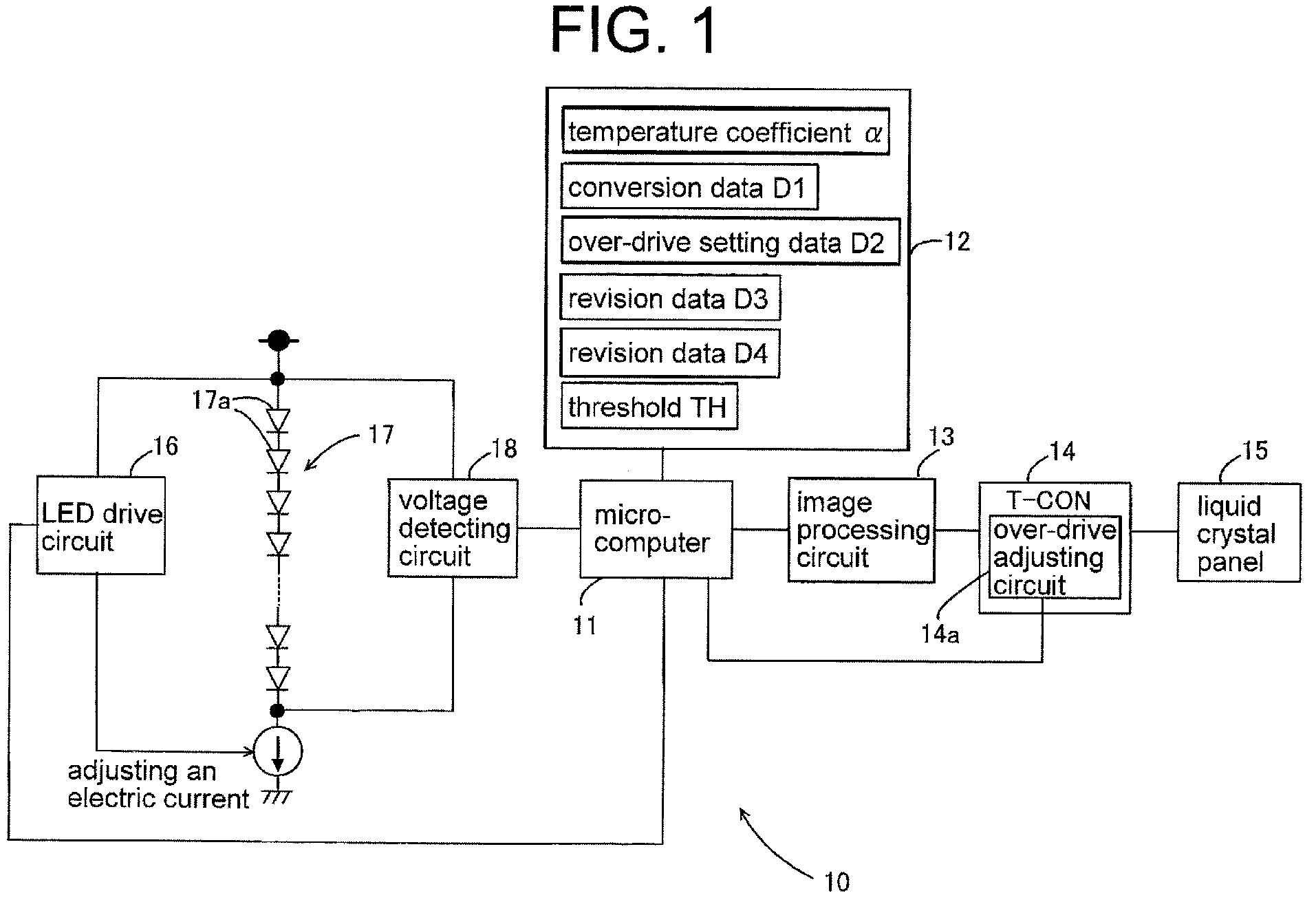
- Figure 1 is a block diagram showing a structure of the display device.
- Figure 2 is a figure showing the relationship between the voltage of the LED and the temperature.
- the display device can be comprised of an over-drive adjusting unit that can adjust response time of the liquid crystal panel for a change of gradation of image.
- the temperature calculating unit calculates an environmental temperature of the display device based on the temperature of the LED, and the control unit causes the over-drive adjusting unit to change setting of the response time depending on the environmental temperature.
- the control unit controls a LED drive unit that adjust an electric current to the LED in order to reduce the electric current or cut off the electric current to the LED by the LED drive unit.
- control unit processes chromaticity adjustment of the LED by controlling the LED drive unit that adjusts an electric current to be supplied to the LED, and/or color correction for the image to be displayed on the liquid crystal panel.
- a display device with an illumination unit that causes a plurality of LED to emit light as a back-light of a liquid crystal panel comprises a voltage detecting circuit that detects a forward voltage drop in the LED, a memory that records certain information beforehand, a microcomputer that carries out certain controls based on the temperature of the LED, a LED drive circuit that adjusts an electric current to be supplied to the LED, an over-drive adjusting circuit that adjusts response time of the liquid crystal panel for a change of gradation of image, and an image processing circuit that performs color correction for the image to be displayed on the liquid crystal panel, wherein the memory at least records a temperature coefficient of the LED, a conversion data showing conversion relationship between the temperature of the LED and an environmental temperature of the display device based on electricity consumption of the LED and thermal resistance that is peculiar to the display device, an over-drive setting data that configures correspondence relationship between the environmental temperature and the response time by the over-drive adjusting circuit, a revision data about color revision that has been decided in correspondence
- FIG. 1 shows a schematic block diagram of the display device 10 of the embodiment.
- the display device 10 may be a television (a liquid crystal panel television) with receiving function of the television broadcasting signal, or a display that inputs picture signal from external devices.
- the display device 10 comprises at least a microcomputer 11, a storage device (a memory) 12, an image processing circuit 13, a timing controller (T - CON) 14, a liquid crystal panel 15, a LED drive circuit 16, a back-light 17 and voltage detecting circuit 18.
- the microcomputer 11 is connected to the memory 12, the image processing circuit 13, the T - CON14, the LED drive circuit 16, and the voltage detecting circuit 18.
- the microcomputer 11 is equipped with a CPU, a ROM, a RAM. And the microcomputer 11 runs predetermined programs which are stored in ROM while using the RAM as working area. Then the microcomputer 11 controls each section of the display device 10 (while carrying out each operations as explained later), and hereby communicates with the each section.
- the image processing circuit 13 inputs a picture signal as displaying obj ect from a tuner (not illustrated) or external equipments.
- the image processing circuit 13 carries out various image processing such as scaling operations for the input picture signals depending on the number of the pixels of the liquid crystal panel 15, color correcting operations, and edge emphasizing operations. Then the image processing circuit 13 generates video signal that expresses a picture for a full screen and outputs it to the T-CON 14.
- the T-CON 14 stores the video signal temporarily in a frame memory (not illustrated).
- the T-CON 14 outputs drive signal corresponding to the stored video signal to the liquid crystal panel 15 at scheduled timing.
- the liquid crystal panel 15 comprises a large number of arranged pixels, and the T-CON 14 drives each pixel of the liquid crystal panel 15 to display a picture based on the video signal.
- the T-CON 14 is equipped with an over-drive (OD) adjusting circuit 14a.
- the over-drive adjusting circuit 14a adjusts response time of the liquid crystal panel that corresponds to change of gradation of the picture (image).
- the over-drive adjusting circuit 14a temporarily outputs a certain voltage (over-drive (OD) voltage) that is higher than the ordinary drive signal that corresponds to the gradation value of the video signal to the liquid crystal panel 15 in order to increase the response time. Namely, the over-drive adjusting circuit 14a can change the response time by adjusting the over-drive voltage.
- OD over-drive
- the back-light 17 is an illumination unit comprising LED lines each of them are made of a series circuit of a plurality of LEDs 17, and light the liquid crystal panel 15 from its back side.
- Figure 1 exemplifies only one LED line in back-light 17.
- the entire screen area of the liquid crystal panel 15 is covered by a plurality of such LED lines.
- the back-light 17 may be comprised of a plurality of different colored LEDs 17a. More concretely, a plurality of LED lines consisting of LEDs 17a that emit red (R) color light, LED lines consisting of LEDs 17a that emits green (G) color light, and LED lines consisting of LEDs 17a that emits blue (B) color light are equipped.
- a LED drive circuit 16 can adjust brightness value of the LED 17a by adjusting electric current to be supplied for the LED 17a.
- the LED drive circuit 16 can dim the back-light 17 locally. In order to do so, the LED drive circuit 16 may adjust electric current supplied to at each LED line unit, or may adjusts the electric current supplied to the LED line at each predetermined area, or may adjusts the electric current separately at each LEDs.
- a voltage detecting circuit 18 detects forward voltage drop VF of the LED 17a.
- the voltage detecting circuit 18 may detect the forward voltage drop VF at a plurality of LEDs 17a that constitute a LED line, or may detect forward voltage drop VF at a LED 17a, or may detect mean value of a plurality of the forward voltage drop VF at a plurality of LEDs 17a.
- the voltage detecting circuit 18 may detect one forward voltage drop VF for the entire back-light 17, or may detect a plurality of forward voltage drops VF representing each area of the back-light 17.
- the voltage detecting circuit 18 may detect the forward voltage drop VF of each different colored LEDs 17a, or may detect the forward voltage drop VF of each different colored LEDs 17a for an entire back-light 17, or may detect the forward voltage drop VF of each different colored LEDs 17a for each area. Then the voltage detecting circuit 18 outputs detected results to the microcomputer 11.
- the microcomputer 11 inputs the forward voltage drop VF from the voltage detecting circuit 18, and read out temperature coefficient ⁇ of LED 17a stored beforehand in memory 12. Then the microcomputer 11 calculates temperature Tj of LED 17a based on the forward voltage drop VF and the temperature coefficient ⁇ .
- the Temperature Tj is equivalent to the junction temperature of semiconductors.
- the temperature coefficient ⁇ is the amount of change of the voltage at each increase of 1 degree Celsius temperature, and, for example, is a value of -2 to - 4 [mV/degree Celsius]. In this embodiment, a standard voltage in the stable state (for example, 25 degrees Celsius) is set.
- the microcomputer 11 divides the forward voltage drop VF (absolute value) by the temperature coefficient ⁇ (absolute value) at first, thus calculates variation amount of temperature corresponding to the forward voltage drop VF. Then the microcomputer 11 calculates temperature Tj of the LED 17a by adding the variation amount of temperature to the above mentioned stable state temperature 25 degrees Celsius.
- the voltage detecting circuit 18 and the microcomputer 11 correspond to the temperature calculating unit.
- the microcomputer 11 divides the forward voltage drop VF by ( ⁇ x N), then calculates the variation amount for the forward voltage drop VF.
- Figure 2 shows relationship between voltage V at anode side of the LED 17a and temperature Tj by a linear function.
- the voltage V decreases in proportion to the increase of the temperature Tj linearly as shown in Figure 2 .
- the temperature Tj increases much more as the forward voltage drop VF by LED 17a increases.
- the degree of inclination of the linear function corresponds to the temperature coefficient ⁇ .
- the microcomputer 11 calculates the temperature Tj at each different colored LED 17a based on the temperature coefficient ⁇ stored for each of the different colored LED 17a in the memory 12 beforehand and the forward voltage drop VF for each of the different colored LED 17a. In other words the temperature coefficient ⁇ s may become different value at each different colored LED 17a.
- one temperature Tj that is generated by a plurality of LEDs 17a of an entire back-light 17 is calculated.
- the temperature Tjs at each area are calculated.
- a set of the forward voltage drop VF at each different colored LEDs 17a is detected for an entire back-light 17
- one set of temperature Tj at each different colored LED 17a is calculated as a representative value for an entire back-light 17.
- a group of temperature Tj at each different colored LED 17a for each area is calculated.
- the microcomputer 11 calculates environmental temperature of the display device 10 based on the temperature Tj. More concretely, the microcomputer 11 refers to the conversion data D1 (a conversion function) stored beforehand in the memory 12 that corresponds to converting relationship between the temperature Tj and the environmental temperature Ta. Then the microcomputer 11 calculates environmental temperature Ta based on the calculated temperature Tj and the conversion function.
- Rja is a thermal resistance peculiar to the display device 10, and is a prescribed numerical value.
- W is electricity consumption of the LED 17a. The electricity consumption W may be calculated based on the electric current supplied LED 17a and the voltage, or may be a numerical value prescribed beforehand.
- the microcomputer 11 calculates one environmental temperature Ta for the display device 10.
- the microcomputer 11 calculates the environmental temperature Tas for each area of the screen are of the liquid crystal panel 15.
- the microcomputer 11 calculates one environmental temperature Ta for the display device 10 based on a peculiar temperature Tj for a peculiar color that constitute each set. Further the microcomputer 11 may calculate environmental temperature Tas for each set based on each temperature Tjs for each color that corresponds to each set, then averages each environmental temperature Tas, thus calculates one environmental temperature Ta for the display device 10.
- the microcomputer 11 calculates the environmental temperature Ta for each area of the screen of the liquid crystal panel 15 based on the temperature Tj for the peculiar colored temperature Tj that corresponds to each set.
- the microcomputer 11 may calculates the environmental temperature Ta based on each of the temperature Tj for each color that corresponds to each set.
- the microcomputer 11 averages each temperature Tas at each set for each area, thus calculates environmental temperature Ta for each area of the screen of the liquid crystal panel 15.
- the microcomputer 11 controls emission of light by LED and/or displaying of image on the liquid crystal panel 15 based on the temperature Tj and the temperature Ta.
- a plurality of control operations (the 1st control operation - 4th control operation) based on the temperature Tj and the environmental temperature Ta are explained.
- the display device 10 may carry out all of the following control operations, or may carry out some the following control operations.
- Over-drive (OD) setting data D2 is stored in memory 12 beforehand.
- Over-drive setting data D2 is a table that is prescribed of corresponding relationship between the response time by the over-drive adjusting circuit 14a and the environmental temperature Ta.
- the microcomputer 11 refers to the over-drive setting data D2, and decides the response time corresponding to the calculated environmental temperature Ta.
- the microcomputer 11 notifies the over-drive adjusting circuit 14a of the T-CON 14 of the decided response time.
- the over-drive adjusting circuit 14a changes a value of the over-drive voltage that is already set to the value that corresponds to the notified response time.
- the liquid crystal panel has the characteristic that the response time becomes slow in the environment where temperature is low. Therefore fast response time is set to lower environmental temperature in the over-drive setting data D2.
- the over-drive voltage is set higher.
- the response time notified to the over-drive adjusting circuit 14a is also one. Therefore, the over-drive adjusting circuit 14a changes the response time with the same over-drive voltage as for the entire screen area of the liquid crystal panel 15.
- the microcomputer 11 calculates environmental temperature Ta for each area of the screen of the liquid crystal panel 15, a plurality of response time corresponding to the environmental temperature Ta at each area are notified to the over-drive adjusting circuit 14a. Therefore, the over-drive adjusting circuit 14a changes response time at each area of the liquid crystal panel 15.
- Revision data D3 is prescribed for color correction corresponding to the temperature Tj. And such Revision data D3 is stored in the memory 12 beforehand. For example, color taste (chromaticity) of back-light 17 changes depending on a change of the temperature Tj. Based on the relationship, the image is revised in order to deny the change of the color taste. Such that the image will be revised in order to deny the change of the color taste, the revision data D3 depending on a value of temperature Tj is saved.
- the revision data D3 is a set of revision data to revise the image that will be an object to be displayed on the liquid crystal panel 15. For example, it is a correction function such as each RGB applied to each gradation value of RGB of the image.
- the table that correspondences a revision data D3 (correction function for each RGB) to a temperature Tj, or the table that correspondences a revision data D3 (correction function for each RGB) to a combination of temperature Tjs for each different colored LED 17a is stored.
- the microcomputer 11 retrieves the revision data D3 corresponding to the calculated temperature Tj from the memory 12. Then the microcomputer 11 notifies the image processing circuit 13 of the retrieved revision data D3. And the microcomputer 11 have the image processing circuit 13 carry out color correcting operations based on the revision data D3. In other words, the image processing circuit 13 revises RGB gradation value for each pixels that constitute the picture, a processing object, by the revision data D3 in real time. For example, the color taste of the back-light 17 can be unmatched with an ideal white in the design when the temperature Tj is too high. A color correction denying such gap will be carried out to the picture. Therefore, regardless of the temperature Tj, the quality of the picture displayed on the liquid crystal panel 15 will be kept.
- the microcomputer 11 calculates one temperature Tj for an entire back-light 17, (or when one set of temperature Tjs for each different colored LED 17a is calculated for an entire back-light 17), a number of the revision data D3 that will be notified to the image processing circuit 13 is one. And the image processing circuit 13 carries out the revision by the same revision data D3 for all pixels of the picture.
- the microcomputer 11 calculates temperature Tj for each area of the back-light 17, (or when the microcomputer 11 calculates each set of the temperature Tjs for each different colored LED 17a for each area of the back-light 17)
- the revision data D3 corresponding to the temperature Tj for each area will be notified to the image processing circuit 13.
- the image processing circuit 13 carries out the revision for each pixel of the picture by the revision data D3 corresponding to each are.
- the microcomputer 11 have the LED drive circuit 16 adjust the electric current to be supplied to the LED 17a based on the revision data D4 corresponding to the temperature Tj of the LED 17a.
- the revision data D4 is a kind of revision data for color correction that corresponds to the temperature Tj.
- the color taste (chromaticity) of the back-light 17 becomes bluish white when the temperature Tj is too high.
- Control data reducing the electric current that the LED drive circuit 16 supplies to the LED 17a in order to deny the change of the chromaticity is stored beforehand as the revision data D4 that corresponds to each value of the temperature Tj.
- the revision data D4 may be control data that is prescribed of an amount of electric current.
- the revision data D4 may be the amount of electric current that will be supplied to each colored LEDs 17a such as red (R), green (G), and blue (B).
- R red
- G green
- B blue
- a table that correspondences a revision data D4 (control data for each RGB) to a temperature Tj, or a table that correspondences a revision data D4 (control data for each RGB) to a combination of temperature Tj for each different colored LEDs 17a is stored.
- the microcomputer 11 retrieves a revision data D4 that corresponds to the calculated temperature Tj from the memory 12. Then the microcomputer 11 notifies the LED drive circuit 16 of the retrieved revision data D4. And the microcomputer 11 have the LED drive circuit 16 carry out operations based on the revision data D4. In other words, the LED drive circuit 16 adjust electric current supply to the LED 17a for each color of RGB based on the revision data D4. For example, color taste (chromaticity) of back-light 17 becomes the bluish white when temperature Tj is too high. In this case, since the amount of electric current will be revised based on revision data D4, a change of the chromaticity will be resolved. As a result, the chromaticity of back-light 17 becomes ideal.
- the microcomputer 11 calculates one temperature Tj for an entire back-light 17 (or when the microcomputer 11 calculates a set of temperature Tj for each different colored 17a for an entire back-light 17), a number of the revision data D4 notified to the LED drive circuit 16 is one. And the LED drive circuit 16 carries out the adjustment by the same revision data D4 to electric current supply for each LED 17a that constitutes the back-light 17.
- the microcomputer 11 calculates temperature Tj for each area of the back-light 17, (or when the microcomputer 11 calculates each set of the temperature Tjs for each different colored LED 17a for each area of the back-light 17), the revision data D4 corresponding to the temperature Tj for each area will be notified to the LED drive circuit 16. And the LED drive circuit 16 carries out electric current adjustment for each LED 17a of the back-light 17 by the revision data D4 that corresponds to each area.
- the microcomputer 11 carries out protection function for LED 17a when the temperature Tj of LED 17a becomes higher than the predetermined threshold value TH in order to prevent shortening of life or destruction of the LED.
- Threshold TH is stored beforehand in the memory 12.
- the microcomputer 11 compares the threshold TH with the calculated temperature Tj.
- the microcomputer 11 notifies the LED drive circuit 16 to perform protection function when the temperature Tj becomes higher than the threshold TH.
- the microcomputer 11 may compare the highest temperature Tj in the combination and threshold TH.
- the microcomputer 11 may compare threshold TH with each of the temperature Tj for each different colored LED 17a.
- the LED drive circuit 16 When the LED drive circuit 16 receives the notice of the performance of the protection function from the microcomputer 11, the LED drive circuit 16 reduces electric current supply to the LED 17a to predetermined amount. Hereby, the temperature of LED 17a reduces, shortening of life or destruction of the LED will be prevented.
- the microcomputer 11 compares threshold TH with temperature Tj of each different colored LED 17a. If the microcomputer detects temperature Tj of LED 17a for a part of the different color (for example R) exceeds the threshold TH, the microcomputer 11 may notifies the LED drive circuit 16 to perform the protection function only for the part of different colors. Then the LED drive circuit 16 reduces the electric current supply to the colored LED 17a to predetermined amount.
- the microcomputer 11 calculates one temperature Tj for an entire back-light 17 (or when the microcomputer 11 calculates one set of the temperature Tjs for each different colored LED 17a for an entire area of the back-light 17), the microcomputer 11 notifies the LED drive circuit 16 to perform the protection function for an entire area of the back-light 17. Then the LED drive circuit 16 performs the current supply adjustment depending on the notice.
- the microcomputer 11 calculates the temperature Tj for each area of the back-light 17 (or when the microcomputer 11 calculates a set of temperature Tj for each different colored LED 17a at each area of the back-light 17)
- the microcomputer 11 compares the temperature Tj and threshold TH for each area. And, based on the result of the comparison for each area, the microcomputer 11 notifies the LED drive circuit 16 whether to perform the protection function for each area. Then the LED drive circuit 16 performs current supply adjustment for each area based on this notice.
- the LED drive circuit 16 may cut off electric current supply to LED 17a when the LED drive circuit 16 receives the notice to perform the protection function from microcomputer 11. In other words, it stops the emission of light by the back-light 17. However, when the LED drive circuit 16 cuts off electric current supply to LED 17a. the LED drive circuit 16 basically does not carry out the light emission control or controls based on area. And the LED drive circuit 16 stops electric current supply to all LED 17a constituting the back-light 17.
- the microcomputer 11 calculates the temperature Tj of the LED 17a based on the forward voltage drop VF of LED 17a as an illumination unit, and further calculates environmental temperature Ta using the temperature Tj, and based on the calculated temperature Tj, Ta, the microcomputer 11 controls the emission of light of LED 17a or display on the liquid crystal panel 15.
- the temperature of the LED may be adequately acquired.
- operations to prevent shortening of life or destruction of the LED (protection function) or operations to keep the quality of display (color and response time of the liquid crystal panel) can be adequately performed.
Landscapes
- Engineering & Computer Science (AREA)
- Physics & Mathematics (AREA)
- Computer Hardware Design (AREA)
- General Physics & Mathematics (AREA)
- Theoretical Computer Science (AREA)
- Control Of Indicators Other Than Cathode Ray Tubes (AREA)
- Circuit Arrangement For Electric Light Sources In General (AREA)
- Liquid Crystal Display Device Control (AREA)
- Liquid Crystal (AREA)
Abstract
Description
- The present application is related to the Japanese Patent Application No.
2010-139857, June 18, 2010 - This invention relates to a display device.
- A display device that uses an illumination unit as a back-light of a liquid crystal panel is known. Especially the illumination unit comprises a plurality of LED (Light Emitting Diode) to emit light for the back-light. When the LED emit light, the temperature of the LED becomes high. When the temperature of the LED becomes high enough over a certain temperature, it causes decreasing of brightness of the LED, shortening of life of the LED, and destruction of the LED. The temperature of the LED affects quality of displaying picture on the liquid crystal panel. Therefore, it is necessary to properly detect temperature of the LED as the illumination device.
- A tip temperature monitoring circuit is disclosed in the Japanese Patent Application Publication No.
2008-152087 2008-152088 - Temperature sensors such as a thermistor has been used to detect the temperature of the LED so far. However, the cost of the product (a display device) would be increased if a sensor for detecting the temperature is equipped individually just for the purpose. In addition, the documents mentioned above disclose a device that detects the temperature of the gate driver IC, and it does not disclose a device to detect the temperature of the LED for the illumination device. Therefore the disclosed device could not operate to reflect the temperature of the LED as the illumination device precisely. As mentioned above, the high temperature of the LED as the illumination device causes various problems. However, those problems has not been solved correctly.
- The present invention provides a display device that can detect the temperature of the LED as the illumination device precisely with low cost, and can carry out various processing appropriately based on the detected temperature.
- One embodiment of the present invention comprises, in a display device that is equipped with an illumination unit that causes a plurality of LED to emit light as a back-light of the liquid crystal panel; a temperature calculating unit that detects a forward voltage drop of the LED, and calculates a temperature of the LED based on the detected forward voltage drop; and a control unit that controls an emission of light of the LED and/or a display of image on the liquid crystal panel based on the calculated temperature of the LED.
- According to the above mentioned embodiment, in the display device, the temperature of the LED is calculated based on the forward voltage drop of the LED as the illumination device, and the display of picture on the liquid crystal panel and/or the emission of light of the LED is controlled. Therefore, the temperature of the LED is adequately detected without installation of the sensors for detecting temperature of the LED. In other words the cost is decreased being compared with conventional invention. In addition, based on the temperature of the LED, the display device can adequately perform controlling process to prevent shortening of life or destruction of the LED, or controlling process to assure the quality of displaying picture on the liquid crystal panel.
-
Figure 1 is a block diagram showing a structure of the display device.Figure 2 is a figure showing the relationship between the voltage of the LED and the temperature. - As one embodiment of the present invention, the display device can be comprised of an over-drive adjusting unit that can adjust response time of the liquid crystal panel for a change of gradation of image. The temperature calculating unit calculates an environmental temperature of the display device based on the temperature of the LED, and the control unit causes the over-drive adjusting unit to change setting of the response time depending on the environmental temperature.
In addition, as another embodiment of the present invention, when the temperature of the LED increases over a predetermined threshold value, the control unit controls a LED drive unit that adjust an electric current to the LED in order to reduce the electric current or cut off the electric current to the LED by the LED drive unit.
In addition, as another embodiment of the present invention, based on a revision data that corresponds to the temperature of the LED beforehand, the control unit processes chromaticity adjustment of the LED by controlling the LED drive unit that adjusts an electric current to be supplied to the LED, and/or color correction for the image to be displayed on the liquid crystal panel. - In addition, as another more detailed embodiment of the present invention, a display device with an illumination unit that causes a plurality of LED to emit light as a back-light of a liquid crystal panel comprises
a voltage detecting circuit that detects a forward voltage drop in the LED,
a memory that records certain information beforehand,
a microcomputer that carries out certain controls based on the temperature of the LED,
a LED drive circuit that adjusts an electric current to be supplied to the LED,
an over-drive adjusting circuit that adjusts response time of the liquid crystal panel for a change of gradation of image, and
an image processing circuit that performs color correction for the image to be displayed on the liquid crystal panel, wherein
the memory at least records a temperature coefficient of the LED, a conversion data showing conversion relationship between the temperature of the LED and an environmental temperature of the display device based on electricity consumption of the LED and thermal resistance that is peculiar to the display device, an over-drive setting data that configures correspondence relationship between the environmental temperature and the response time by the over-drive adjusting circuit, a revision data about color revision that has been decided in correspondence with the temperature of the LED, and a predetermined threshold value for the temperature of the LED, and
the microcomputer
calculates the temperature of the LED based on the detected forward voltage drop and the temperature coefficient, and
calculates the environmental temperature based on the calculated temperature of the LED and the conversion data, and
decides response time that corresponds to the calculated environmental temperature by referring the over-drive setting data, then
controls the over-drive adjusting circuit in order to change the setting of the response time to the decided response time, and
in case of the temperature of the LED increases over the predetermined threshold value, controls the LED drive circuit in order to make the electric current that the LED drive circuit supplies to the LED to be reduced or cut off the current to be supplied to the LED by the LED drive circuit, and
based on the revision data that corresponds to the temperature of the LED, carries out chromaticity correction of the LED by controlling the LED drive circuit and/or color correction for the image to be displayed on the liquid crystal panel. - The embodiment of the present invention will be explained hereinafter referring to the drawings as follows.
Figure 1 shows a schematic block diagram of thedisplay device 10 of the embodiment. Thedisplay device 10 may be a television (a liquid crystal panel television) with receiving function of the television broadcasting signal, or a display that inputs picture signal from external devices. Thedisplay device 10 comprises at least amicrocomputer 11, a storage device (a memory) 12, animage processing circuit 13, a timing controller (T - CON) 14, aliquid crystal panel 15, aLED drive circuit 16, a back-light 17 andvoltage detecting circuit 18. - The
microcomputer 11 is connected to thememory 12, theimage processing circuit 13, the T - CON14, theLED drive circuit 16, and thevoltage detecting circuit 18. Themicrocomputer 11 is equipped with a CPU, a ROM, a RAM. And themicrocomputer 11 runs predetermined programs which are stored in ROM while using the RAM as working area. Then themicrocomputer 11 controls each section of the display device 10 (while carrying out each operations as explained later), and hereby communicates with the each section.
Theimage processing circuit 13 inputs a picture signal as displaying obj ect from a tuner (not illustrated) or external equipments. Theimage processing circuit 13 carries out various image processing such as scaling operations for the input picture signals depending on the number of the pixels of theliquid crystal panel 15, color correcting operations, and edge emphasizing operations. Then theimage processing circuit 13 generates video signal that expresses a picture for a full screen and outputs it to the T-CON 14. - The T-
CON 14 stores the video signal temporarily in a frame memory (not illustrated). The T-CON 14 outputs drive signal corresponding to the stored video signal to theliquid crystal panel 15 at scheduled timing. Theliquid crystal panel 15 comprises a large number of arranged pixels, and the T-CON 14 drives each pixel of theliquid crystal panel 15 to display a picture based on the video signal. The T-CON 14 is equipped with an over-drive (OD) adjustingcircuit 14a. Theover-drive adjusting circuit 14a adjusts response time of the liquid crystal panel that corresponds to change of gradation of the picture (image). Theover-drive adjusting circuit 14a temporarily outputs a certain voltage (over-drive (OD) voltage) that is higher than the ordinary drive signal that corresponds to the gradation value of the video signal to theliquid crystal panel 15 in order to increase the response time. Namely, theover-drive adjusting circuit 14a can change the response time by adjusting the over-drive voltage. - The back-
light 17 is an illumination unit comprising LED lines each of them are made of a series circuit of a plurality ofLEDs 17, and light theliquid crystal panel 15 from its back side.Figure 1 exemplifies only one LED line in back-light 17. However, the entire screen area of theliquid crystal panel 15 is covered by a plurality of such LED lines. In addition, the back-light 17 may be comprised of a plurality of differentcolored LEDs 17a. More concretely, a plurality of LED lines consisting ofLEDs 17a that emit red (R) color light, LED lines consisting ofLEDs 17a that emits green (G) color light, and LED lines consisting ofLEDs 17a that emits blue (B) color light are equipped. As shown in the figure, Forward voltage is applied on each of the LED lines. ALED drive circuit 16 can adjust brightness value of theLED 17a by adjusting electric current to be supplied for theLED 17a. TheLED drive circuit 16 can dim the back-light 17 locally. In order to do so, theLED drive circuit 16 may adjust electric current supplied to at each LED line unit, or may adjusts the electric current supplied to the LED line at each predetermined area, or may adjusts the electric current separately at each LEDs. - A
voltage detecting circuit 18 detects forward voltage drop VF of theLED 17a. Thevoltage detecting circuit 18 may detect the forward voltage drop VF at a plurality ofLEDs 17a that constitute a LED line, or may detect forward voltage drop VF at aLED 17a, or may detect mean value of a plurality of the forward voltage drop VF at a plurality ofLEDs 17a. In addition, thevoltage detecting circuit 18 may detect one forward voltage drop VF for the entire back-light 17, or may detect a plurality of forward voltage drops VF representing each area of the back-light 17. When there are differentcolored LEDs 17a, thevoltage detecting circuit 18 may detect the forward voltage drop VF of each differentcolored LEDs 17a, or may detect the forward voltage drop VF of each differentcolored LEDs 17a for an entire back-light 17, or may detect the forward voltage drop VF of each differentcolored LEDs 17a for each area. Then thevoltage detecting circuit 18 outputs detected results to themicrocomputer 11. - The
microcomputer 11 inputs the forward voltage drop VF from thevoltage detecting circuit 18, and read out temperature coefficient α ofLED 17a stored beforehand inmemory 12. Then themicrocomputer 11 calculates temperature Tj ofLED 17a based on the forward voltage drop VF and the temperature coefficient α. The Temperature Tj is equivalent to the junction temperature of semiconductors. The temperature coefficient α is the amount of change of the voltage at each increase of 1 degree Celsius temperature, and, for example, is a value of -2 to - 4 [mV/degree Celsius]. In this embodiment, a standard voltage in the stable state (for example, 25 degrees Celsius) is set. When the forward voltage drop VF at aLED 17a or the forward voltage drop VF as the mean value of the forward voltage drop VF at a plurality ofLEDs 17a is detected, themicrocomputer 11 divides the forward voltage drop VF (absolute value) by the temperature coefficient α (absolute value) at first, thus calculates variation amount of temperature corresponding to the forward voltage drop VF. Then themicrocomputer 11 calculates temperature Tj of theLED 17a by adding the variation amount of temperature to the above mentioned stable state temperature 25 degrees Celsius. Thevoltage detecting circuit 18 and themicrocomputer 11 correspond to the temperature calculating unit. When the forward voltage drop VF at a plurality ofLED 17a (N units) is detected, themicrocomputer 11 divides the forward voltage drop VF by (α x N), then calculates the variation amount for the forward voltage drop VF. -
Figure 2 shows relationship between voltage V at anode side of theLED 17a and temperature Tj by a linear function. The voltage V decreases in proportion to the increase of the temperature Tj linearly as shown inFigure 2 . In other words, the temperature Tj increases much more as the forward voltage drop VF byLED 17a increases. The degree of inclination of the linear function corresponds to the temperature coefficient α. - When the forward voltage drop VF is detected at each of the different
colored LED 17a as mentioned above, themicrocomputer 11 calculates the temperature Tj at each differentcolored LED 17a based on the temperature coefficient α stored for each of the differentcolored LED 17a in thememory 12 beforehand and the forward voltage drop VF for each of the differentcolored LED 17a. In other words the temperature coefficient αs may become different value at each differentcolored LED 17a. - When one forward voltage drop VF is detected for an entire back-
light 17, one temperature Tj that is generated by a plurality ofLEDs 17a of an entire back-light 17 is calculated. When the forward voltage drop VF is detected at each area of the back-light 17, the temperature Tjs at each area are calculated. When a set of the forward voltage drop VF at each differentcolored LEDs 17a is detected for an entire back-light 17, one set of temperature Tj at each differentcolored LED 17a is calculated as a representative value for an entire back-light 17. When the forward voltage drop VF at each differentcolored LED 17a at each area of the back-light 17 are detected, a group of temperature Tj at each differentcolored LED 17a for each area is calculated. - Then the
microcomputer 11 calculates environmental temperature of thedisplay device 10 based on the temperature Tj. More concretely, themicrocomputer 11 refers to the conversion data D1 (a conversion function) stored beforehand in thememory 12 that corresponds to converting relationship between the temperature Tj and the environmental temperature Ta. Then themicrocomputer 11 calculates environmental temperature Ta based on the calculated temperature Tj and the conversion function. The conversion function is expressed by the following expression (1).
display device 10, and is a prescribed numerical value. Further, W is electricity consumption of theLED 17a. The electricity consumption W may be calculated based on the electric current suppliedLED 17a and the voltage, or may be a numerical value prescribed beforehand. - When one temperature Tj for an entire back-
light 17 is calculated, themicrocomputer 11 calculates one environmental temperature Ta for thedisplay device 10. When temperature Tjs at each area of the back-light 17 are calculated, themicrocomputer 11 calculates the environmental temperature Tas for each area of the screen are of theliquid crystal panel 15. In addition, when a set of temperature Tj for each differentcolored LED 17a is calculated as a representative value for the back-light 17, themicrocomputer 11 calculates one environmental temperature Ta for thedisplay device 10 based on a peculiar temperature Tj for a peculiar color that constitute each set. Further themicrocomputer 11 may calculate environmental temperature Tas for each set based on each temperature Tjs for each color that corresponds to each set, then averages each environmental temperature Tas, thus calculates one environmental temperature Ta for thedisplay device 10. In addition, when a set of temperature Tj for each differentcolored LED 17a is calculated, themicrocomputer 11 calculates the environmental temperature Ta for each area of the screen of theliquid crystal panel 15 based on the temperature Tj for the peculiar colored temperature Tj that corresponds to each set. Themicrocomputer 11 may calculates the environmental temperature Ta based on each of the temperature Tj for each color that corresponds to each set. And themicrocomputer 11 averages each temperature Tas at each set for each area, thus calculates environmental temperature Ta for each area of the screen of theliquid crystal panel 15. - Then the
microcomputer 11 controls emission of light by LED and/or displaying of image on theliquid crystal panel 15 based on the temperature Tj and the temperature Ta. Hereinafter, a plurality of control operations (the 1st control operation - 4th control operation) based on the temperature Tj and the environmental temperature Ta are explained. Thedisplay device 10 may carry out all of the following control operations, or may carry out some the following control operations. - (1st control operation) Over-drive (OD) setting data D2 is stored in
memory 12 beforehand. Over-drive setting data D2 is a table that is prescribed of corresponding relationship between the response time by theover-drive adjusting circuit 14a and the environmental temperature Ta. At first, themicrocomputer 11 refers to the over-drive setting data D2, and decides the response time corresponding to the calculated environmental temperature Ta. Next, themicrocomputer 11 notifies theover-drive adjusting circuit 14a of the T-CON 14 of the decided response time. Then theover-drive adjusting circuit 14a changes a value of the over-drive voltage that is already set to the value that corresponds to the notified response time. Hereby, the response time is being changed. The liquid crystal panel has the characteristic that the response time becomes slow in the environment where temperature is low. Therefore fast response time is set to lower environmental temperature in the over-drive setting data D2. As a result, when the environmental temperature Ta is low, the over-drive voltage is set higher. Thus it prevents the response time of the liquid crystal panel decreases when the environmental temperature Ta is low. - In addition, when
microcomputer 11 calculates one environmental temperature Ta as for thedisplay device 10, the response time notified to theover-drive adjusting circuit 14a is also one. Therefore, theover-drive adjusting circuit 14a changes the response time with the same over-drive voltage as for the entire screen area of theliquid crystal panel 15. In contrast, when themicrocomputer 11 calculates environmental temperature Ta for each area of the screen of theliquid crystal panel 15, a plurality of response time corresponding to the environmental temperature Ta at each area are notified to theover-drive adjusting circuit 14a. Therefore, theover-drive adjusting circuit 14a changes response time at each area of theliquid crystal panel 15. - (2nd control operation)
Revision data D3 is prescribed for color correction corresponding to the temperature Tj. And such Revision data D3 is stored in thememory 12 beforehand. For example, color taste (chromaticity) of back-light 17 changes depending on a change of the temperature Tj. Based on the relationship, the image is revised in order to deny the change of the color taste. Such that the image will be revised in order to deny the change of the color taste, the revision data D3 depending on a value of temperature Tj is saved. The revision data D3 is a set of revision data to revise the image that will be an object to be displayed on theliquid crystal panel 15. For example, it is a correction function such as each RGB applied to each gradation value of RGB of the image. In thememory 12, the table that correspondences a revision data D3 (correction function for each RGB) to a temperature Tj, or the table that correspondences a revision data D3 (correction function for each RGB) to a combination of temperature Tjs for each differentcolored LED 17a is stored. - At first, the
microcomputer 11 retrieves the revision data D3 corresponding to the calculated temperature Tj from thememory 12. Then themicrocomputer 11 notifies theimage processing circuit 13 of the retrieved revision data D3. And themicrocomputer 11 have theimage processing circuit 13 carry out color correcting operations based on the revision data D3. In other words, theimage processing circuit 13 revises RGB gradation value for each pixels that constitute the picture, a processing object, by the revision data D3 in real time. For example, the color taste of the back-light 17 can be unmatched with an ideal white in the design when the temperature Tj is too high. A color correction denying such gap will be carried out to the picture. Therefore, regardless of the temperature Tj, the quality of the picture displayed on theliquid crystal panel 15 will be kept. When themicrocomputer 11 calculates one temperature Tj for an entire back-light 17, (or when one set of temperature Tjs for each differentcolored LED 17a is calculated for an entire back-light 17), a number of the revision data D3 that will be notified to theimage processing circuit 13 is one. And theimage processing circuit 13 carries out the revision by the same revision data D3 for all pixels of the picture. On the other hand, when themicrocomputer 11 calculates temperature Tj for each area of the back-light 17, (or when themicrocomputer 11 calculates each set of the temperature Tjs for each differentcolored LED 17a for each area of the back-light 17), the revision data D3 corresponding to the temperature Tj for each area will be notified to theimage processing circuit 13. And theimage processing circuit 13 carries out the revision for each pixel of the picture by the revision data D3 corresponding to each are. - (3rd control operation) The
microcomputer 11 have theLED drive circuit 16 adjust the electric current to be supplied to theLED 17a based on the revision data D4 corresponding to the temperature Tj of theLED 17a. As a result, chromaticity revision of theLED 17a will be carried out. The revision data D4 is a kind of revision data for color correction that corresponds to the temperature Tj. For example, the color taste (chromaticity) of the back-light 17 becomes bluish white when the temperature Tj is too high. Control data reducing the electric current that theLED drive circuit 16 supplies to theLED 17a in order to deny the change of the chromaticity is stored beforehand as the revision data D4 that corresponds to each value of the temperature Tj. For example, the revision data D4 may be control data that is prescribed of an amount of electric current. Namely the revision data D4 may be the amount of electric current that will be supplied to eachcolored LEDs 17a such as red (R), green (G), and blue (B). In thememory 12, a table that correspondences a revision data D4 (control data for each RGB) to a temperature Tj, or a table that correspondences a revision data D4 (control data for each RGB) to a combination of temperature Tj for each differentcolored LEDs 17a is stored. - At first, the
microcomputer 11 retrieves a revision data D4 that corresponds to the calculated temperature Tj from thememory 12. Then themicrocomputer 11 notifies theLED drive circuit 16 of the retrieved revision data D4. And themicrocomputer 11 have theLED drive circuit 16 carry out operations based on the revision data D4. In other words, theLED drive circuit 16 adjust electric current supply to theLED 17a for each color of RGB based on the revision data D4. For example, color taste (chromaticity) of back-light 17 becomes the bluish white when temperature Tj is too high. In this case, since the amount of electric current will be revised based on revision data D4, a change of the chromaticity will be resolved. As a result, the chromaticity of back-light 17 becomes ideal. In addition, when themicrocomputer 11 calculates one temperature Tj for an entire back-light 17 (or when themicrocomputer 11 calculates a set of temperature Tj for each different colored 17a for an entire back-light 17), a number of the revision data D4 notified to theLED drive circuit 16 is one. And theLED drive circuit 16 carries out the adjustment by the same revision data D4 to electric current supply for eachLED 17a that constitutes the back-light 17. On the other hand, when themicrocomputer 11 calculates temperature Tj for each area of the back-light 17, (or when themicrocomputer 11 calculates each set of the temperature Tjs for each differentcolored LED 17a for each area of the back-light 17), the revision data D4 corresponding to the temperature Tj for each area will be notified to theLED drive circuit 16. And theLED drive circuit 16 carries out electric current adjustment for eachLED 17a of the back-light 17 by the revision data D4 that corresponds to each area. - (4th control operation)
Themicrocomputer 11 carries out protection function forLED 17a when the temperature Tj ofLED 17a becomes higher than the predetermined threshold value TH in order to prevent shortening of life or destruction of the LED. Threshold TH is stored beforehand in thememory 12. Themicrocomputer 11 compares the threshold TH with the calculated temperature Tj. Themicrocomputer 11 notifies theLED drive circuit 16 to perform protection function when the temperature Tj becomes higher than the threshold TH. In addition, whenmicrocomputer 11 acquires a combination of the temperature Tj for each differentcolored LED 17a, themicrocomputer 11 may compare the highest temperature Tj in the combination and threshold TH. In addition, themicrocomputer 11 may compare threshold TH with each of the temperature Tj for each differentcolored LED 17a. - When the
LED drive circuit 16 receives the notice of the performance of the protection function from themicrocomputer 11, theLED drive circuit 16 reduces electric current supply to theLED 17a to predetermined amount. Hereby, the temperature ofLED 17a reduces, shortening of life or destruction of the LED will be prevented. In addition, themicrocomputer 11 compares threshold TH with temperature Tj of each differentcolored LED 17a. If the microcomputer detects temperature Tj ofLED 17a for a part of the different color (for example R) exceeds the threshold TH, themicrocomputer 11 may notifies theLED drive circuit 16 to perform the protection function only for the part of different colors. Then theLED drive circuit 16 reduces the electric current supply to thecolored LED 17a to predetermined amount. - In addition, when the
microcomputer 11 calculates one temperature Tj for an entire back-light 17 (or when themicrocomputer 11 calculates one set of the temperature Tjs for each differentcolored LED 17a for an entire area of the back-light 17), themicrocomputer 11 notifies theLED drive circuit 16 to perform the protection function for an entire area of the back-light 17. Then theLED drive circuit 16 performs the current supply adjustment depending on the notice. On the other hand, when themicrocomputer 11 calculates the temperature Tj for each area of the back-light 17 (or when themicrocomputer 11 calculates a set of temperature Tj for each differentcolored LED 17a at each area of the back-light 17), themicrocomputer 11 compares the temperature Tj and threshold TH for each area. And, based on the result of the comparison for each area, themicrocomputer 11 notifies theLED drive circuit 16 whether to perform the protection function for each area. Then theLED drive circuit 16 performs current supply adjustment for each area based on this notice. - In addition, the
LED drive circuit 16 may cut off electric current supply toLED 17a when theLED drive circuit 16 receives the notice to perform the protection function frommicrocomputer 11. In other words, it stops the emission of light by the back-light 17. However, when theLED drive circuit 16 cuts off electric current supply toLED 17a. theLED drive circuit 16 basically does not carry out the light emission control or controls based on area. And theLED drive circuit 16 stops electric current supply to allLED 17a constituting the back-light 17. - According to the present embodiment, the
microcomputer 11 calculates the temperature Tj of theLED 17a based on the forward voltage drop VF ofLED 17a as an illumination unit, and further calculates environmental temperature Ta using the temperature Tj, and based on the calculated temperature Tj, Ta, themicrocomputer 11 controls the emission of light ofLED 17a or display on theliquid crystal panel 15. As a result, without sensors for detecting temperature as prior art, the temperature of the LED may be adequately acquired. In addition, based on the temperature of the LED, operations to prevent shortening of life or destruction of the LED (protection function) or operations to keep the quality of display (color and response time of the liquid crystal panel) can be adequately performed. - While the invention has been particularly shown and described with respect to preferred embodiments thereof, it should be understood by those skilled in the art that the foregoing and other changes in form and detail may be made therein without departing from the spirit and scope of the invention as defined in the appended claims.
Claims (5)
- A display device with an illumination unit that causes a plurality of LED to emit light as a back-light of a liquid crystal panel that comprises
a temperature calculating unit that detects a forward voltage drop of the LED, and calculates a temperature of the LED based on the detected forward voltage drop; and a control unit that controls an emission of light of the LED and/or a display of image on the liquid crystal panel based on the calculated temperature of the LED. - A display device according to claim 1, further comprises
an over-drive adjusting unit that adjusts response time of the liquid crystal panel for a change of gradation of image, and
the temperature calculating unit calculates an environmental temperature of the display device based on the temperature of the LED, and the control unit causes the over-drive adjusting unit to change setting of the response time depending on the environmental temperature. - A display device according to any one of claims 1 or 2, wherein
when the temperature of the LED increases over a predetermined threshold value, the control unit controls a LED drive unit that adjust an electric current to the LED in order to reduce the electric current or cut off the electric current to the LED by the LED drive unit. - A display device according to any one of claims 1 to 3, wherein
based on a revision data that corresponds to the temperature of the LED beforehand, the control unit processes chromaticity adjustment of the LED by controlling a LED drive unit that adjusts an electric current to be supplied to the LED, and/or color correction for the image to be displayed on the liquid crystal panel. - A display device with an illumination unit that causes a plurality of LED to emit light as a back-light of a liquid crystal panel that comprises
a voltage detecting circuit that detects a forward voltage drop in the LED,
a memory that records certain information beforehand,
a microcomputer that carries out certain controls based on the temperature of the LED,
a LED drive circuit that adjusts an electric current to be supplied to the LED,
an over-drive adjusting circuit that adjusts response time of the liquid crystal panel for a change of gradation of image, and
an image processing circuit that performs color correction for the image to be displayed on the liquid crystal panel, wherein
the memory at least records a temperature coefficient of the LED, a conversion data showing conversion relationship between the temperature of the LED and an environmental temperature of the display device based on electricity consumption of the LED and thermal resistance that is peculiar to the display device, an over-drive setting data that configures correspondence relationship between the environmental temperature and the response time by the over-drive adjusting circuit, a revision data about color revision that has been decided in correspondence with the temperature of the LED, and a predetermined threshold value for the temperature of the LED, and
the microcomputer
calculates the temperature of the LED based on the detected forward voltage drop and the temperature coefficient, and
calculates the environmental temperature based on the calculated temperature of the LED and the conversion data, and
decides response time that corresponds to the calculated environmental temperature by referring the over-drive setting data, then
controls the over-drive adjusting circuit in order to change the setting of the response time to the decided response time, and
in case of the temperature of the LED increases over the predetermined threshold value, controls the LED drive circuit in order to make the electric current that the LED drive circuit supplies to the LED to be reduced or cut off the current to be supplied to the LED by the LED drive circuit, and
based on the revision data that corresponds to the temperature of the LED, carries out chromaticity correction of the LED by controlling the LED drive circuit and/or color correction for the image to be displayed on the liquid crystal panel.
Applications Claiming Priority (1)
| Application Number | Priority Date | Filing Date | Title |
|---|---|---|---|
| JP2010139857A JP2012003156A (en) | 2010-06-18 | 2010-06-18 | Display device |
Publications (3)
| Publication Number | Publication Date |
|---|---|
| EP2398013A2 true EP2398013A2 (en) | 2011-12-21 |
| EP2398013A3 EP2398013A3 (en) | 2012-08-22 |
| EP2398013B1 EP2398013B1 (en) | 2013-12-11 |
Family
ID=44735784
Family Applications (1)
| Application Number | Title | Priority Date | Filing Date |
|---|---|---|---|
| EP11169993.0A Not-in-force EP2398013B1 (en) | 2010-06-18 | 2011-06-15 | A display device comprising a temperature calculating unit detecting a forward voltage drop of the LED used as illumination unit |
Country Status (3)
| Country | Link |
|---|---|
| US (1) | US20110310134A1 (en) |
| EP (1) | EP2398013B1 (en) |
| JP (1) | JP2012003156A (en) |
Cited By (1)
| Publication number | Priority date | Publication date | Assignee | Title |
|---|---|---|---|---|
| ITTO20130211A1 (en) * | 2013-03-18 | 2013-06-17 | Giuseppe Quaranta | OPTIMIZATION SYSTEM OF A PHOTOEMECTIVE DEVICE |
Families Citing this family (15)
| Publication number | Priority date | Publication date | Assignee | Title |
|---|---|---|---|---|
| TWI611215B (en) * | 2012-05-09 | 2018-01-11 | 半導體能源研究所股份有限公司 | Display device and electronic device |
| TWI588540B (en) | 2012-05-09 | 2017-06-21 | 半導體能源研究所股份有限公司 | Display device and electronic device |
| JP2013239647A (en) * | 2012-05-16 | 2013-11-28 | Sharp Corp | Light emitting element drive unit, display unit, television receiver, program, and storage medium |
| CN102889273B (en) * | 2012-10-18 | 2015-07-22 | 浙江大学 | Electro-hydraulic system for recycling and releasing potential energy of engineering machinery |
| TWI514919B (en) * | 2013-01-17 | 2015-12-21 | Univ Nat Chi Nan | Optical power control system and optical power control device and pulse generation module group |
| JP6074855B2 (en) * | 2013-06-20 | 2017-02-08 | パナソニックIpマネジメント株式会社 | Lighting apparatus and lighting apparatus using the same |
| US9905170B2 (en) * | 2016-06-20 | 2018-02-27 | GM Global Technology Operations LLC | Control of LED array in a liquid crystal display assembly |
| CN107610641B (en) * | 2017-11-03 | 2024-05-10 | 深圳市联诚发科技股份有限公司 | Automatic correction intelligent device and method for LED display screen |
| JP2019204888A (en) * | 2018-05-24 | 2019-11-28 | 日亜化学工業株式会社 | Light-emitting module and control module |
| US11083055B2 (en) | 2018-09-10 | 2021-08-03 | Lumileds Llc | High speed image refresh system |
| CN113805620A (en) * | 2020-06-12 | 2021-12-17 | 中强光电股份有限公司 | Display device and temperature protection method thereof |
| JP7469565B2 (en) * | 2020-10-09 | 2024-04-16 | ルミレッズ リミテッド ライアビリティ カンパニー | Temperature sensing of micro LED arrays |
| CN114627827B (en) * | 2020-12-08 | 2023-10-24 | 京东方科技集团股份有限公司 | Gray scale compensation method, gray scale compensation module and liquid crystal display device |
| KR20230172079A (en) * | 2022-06-14 | 2023-12-22 | 삼성디스플레이 주식회사 | Display device |
| CN119007669B (en) * | 2024-10-25 | 2025-05-09 | 比亚迪股份有限公司 | Display device control method, storage medium, computer program product, electronic device, display device, and vehicle |
Citations (3)
| Publication number | Priority date | Publication date | Assignee | Title |
|---|---|---|---|---|
| JP2008152088A (en) | 2006-12-19 | 2008-07-03 | Sony Corp | Display device temperature control method and display device |
| JP2008152087A (en) | 2006-12-19 | 2008-07-03 | Sony Corp | Display device and electronic device |
| JP2010139857A (en) | 2008-12-12 | 2010-06-24 | Konica Minolta Business Technologies Inc | Image forming apparatus and method for controlling toner sticking amount |
Family Cites Families (19)
| Publication number | Priority date | Publication date | Assignee | Title |
|---|---|---|---|---|
| JPH07177398A (en) * | 1993-12-20 | 1995-07-14 | Sony Corp | Viewfinder device for video camera |
| US5936604A (en) * | 1994-04-21 | 1999-08-10 | Casio Computer Co., Ltd. | Color liquid crystal display apparatus and method for driving the same |
| US6441558B1 (en) * | 2000-12-07 | 2002-08-27 | Koninklijke Philips Electronics N.V. | White LED luminary light control system |
| JP2005115350A (en) * | 2003-09-17 | 2005-04-28 | Seiko Epson Corp | Temperature measurement device, light source control device, projector, temperature measurement method, and light source control method |
| JP3984214B2 (en) * | 2003-10-21 | 2007-10-03 | ローム株式会社 | Light emission control device |
| WO2006043232A1 (en) * | 2004-10-22 | 2006-04-27 | Koninklijke Philips Electronics N.V. | Method for driving a led based lighting device |
| JP2007096113A (en) * | 2005-09-29 | 2007-04-12 | Hitachi Lighting Ltd | Led light source device |
| KR20070048514A (en) * | 2005-11-04 | 2007-05-09 | 삼성전자주식회사 | Liquid crystal display and method for driving there of |
| JP2007199470A (en) * | 2006-01-27 | 2007-08-09 | Nec Electronics Corp | Liquid crystal panel driving device and liquid crystal display |
| JP2007233061A (en) * | 2006-03-01 | 2007-09-13 | Sharp Corp | Liquid crystal display |
| TWI350498B (en) * | 2006-03-21 | 2011-10-11 | Himax Tech Ltd | Overdriving value generating apparatus and method |
| JP2008116853A (en) * | 2006-11-07 | 2008-05-22 | Canon Inc | LED driving device and liquid crystal display device |
| DE102007029123A1 (en) * | 2007-06-25 | 2009-01-02 | Tridonicatco Schweiz Ag | System and method for detecting the characteristics of a light emitting diode array |
| JP2009020340A (en) * | 2007-07-12 | 2009-01-29 | Renesas Technology Corp | Display device and display device driving circuit |
| KR101422147B1 (en) * | 2007-08-30 | 2014-08-14 | 삼성디스플레이 주식회사 | Liquid crystal display device |
| JP5388441B2 (en) * | 2007-11-08 | 2014-01-15 | キヤノン株式会社 | Light emission control device and light emission control method |
| KR20090058363A (en) * | 2007-12-04 | 2009-06-09 | 삼성전자주식회사 | Display device and display method for compensating optical parameters using forward voltage of light emitting diode |
| EP2245904A2 (en) * | 2008-01-28 | 2010-11-03 | Nxp B.V. | System and method for estimating the junction temperature of a light emitting diode |
| JP4560567B2 (en) * | 2008-04-22 | 2010-10-13 | ティーピーオー ディスプレイズ コーポレイション | Overdrive method for liquid crystal display device and liquid crystal display device |
-
2010
- 2010-06-18 JP JP2010139857A patent/JP2012003156A/en active Pending
-
2011
- 2011-06-03 US US13/152,287 patent/US20110310134A1/en not_active Abandoned
- 2011-06-15 EP EP11169993.0A patent/EP2398013B1/en not_active Not-in-force
Patent Citations (3)
| Publication number | Priority date | Publication date | Assignee | Title |
|---|---|---|---|---|
| JP2008152088A (en) | 2006-12-19 | 2008-07-03 | Sony Corp | Display device temperature control method and display device |
| JP2008152087A (en) | 2006-12-19 | 2008-07-03 | Sony Corp | Display device and electronic device |
| JP2010139857A (en) | 2008-12-12 | 2010-06-24 | Konica Minolta Business Technologies Inc | Image forming apparatus and method for controlling toner sticking amount |
Cited By (2)
| Publication number | Priority date | Publication date | Assignee | Title |
|---|---|---|---|---|
| ITTO20130211A1 (en) * | 2013-03-18 | 2013-06-17 | Giuseppe Quaranta | OPTIMIZATION SYSTEM OF A PHOTOEMECTIVE DEVICE |
| WO2014147653A1 (en) * | 2013-03-18 | 2014-09-25 | Thermoled Srls | Thermal optimization system for light emitters |
Also Published As
| Publication number | Publication date |
|---|---|
| JP2012003156A (en) | 2012-01-05 |
| EP2398013B1 (en) | 2013-12-11 |
| US20110310134A1 (en) | 2011-12-22 |
| EP2398013A3 (en) | 2012-08-22 |
Similar Documents
| Publication | Publication Date | Title |
|---|---|---|
| EP2398013B1 (en) | A display device comprising a temperature calculating unit detecting a forward voltage drop of the LED used as illumination unit | |
| CN102549649B (en) | Liquid crystal display device | |
| US8963826B2 (en) | Video display apparatus including brightness control based on ambient illuminance | |
| US9699861B2 (en) | Light emitting apparatus and method for controlling the same | |
| US7773080B2 (en) | Display device and the driving method which restricts electric power | |
| US10810950B2 (en) | Light source control device, display device, and image processing device | |
| KR101385453B1 (en) | Driving method of light source and back light assembly for carrying out the driving method | |
| EP2515161A1 (en) | Light emitting device for image display, and image display device | |
| US8723784B2 (en) | Brightness control apparatus, display apparatus and lighting apparatus | |
| EP2357636B1 (en) | Display apparatus and control circuit of the same | |
| US20140340437A1 (en) | Video display device | |
| KR101512054B1 (en) | Method of driving light-source, light-source apparatus for performing the method and display apparatus having the light-source apparatus | |
| KR20120120310A (en) | Light emitting device for image display, image display apparatus, and led driver | |
| WO2011004520A1 (en) | Liquid crystal display device and method for controlling display of liquid crystal display device | |
| EP2793216A2 (en) | Image processing method of display device and display device thereof | |
| KR101823701B1 (en) | Display apparatus and method for driving the same | |
| JP2010060746A (en) | Liquid crystal display device | |
| KR101502686B1 (en) | Display device with backlight dimming compensation | |
| US20180061331A1 (en) | Display apparatus, method, and medium for displaying an image | |
| KR102552360B1 (en) | Display Apparatus and Driving Method Thereof | |
| US20120154466A1 (en) | Display control apparatus and control method thereof | |
| US20240135889A1 (en) | Driving Controlling Device And Driving Controlling Method As Well As Information Processing System | |
| JP2009048131A (en) | Liquid crystal display | |
| US20250201204A1 (en) | Fail-safe architecture for local dimming display device | |
| EP4387065A1 (en) | Power supply circuit protection device and power supply circuit protection method |
Legal Events
| Date | Code | Title | Description |
|---|---|---|---|
| AK | Designated contracting states |
Kind code of ref document: A2 Designated state(s): AL AT BE BG CH CY CZ DE DK EE ES FI FR GB GR HR HU IE IS IT LI LT LU LV MC MK MT NL NO PL PT RO RS SE SI SK SM TR |
|
| AX | Request for extension of the european patent |
Extension state: BA ME |
|
| PUAI | Public reference made under article 153(3) epc to a published international application that has entered the european phase |
Free format text: ORIGINAL CODE: 0009012 |
|
| PUAL | Search report despatched |
Free format text: ORIGINAL CODE: 0009013 |
|
| AK | Designated contracting states |
Kind code of ref document: A3 Designated state(s): AL AT BE BG CH CY CZ DE DK EE ES FI FR GB GR HR HU IE IS IT LI LT LU LV MC MK MT NL NO PL PT RO RS SE SI SK SM TR |
|
| AX | Request for extension of the european patent |
Extension state: BA ME |
|
| RIC1 | Information provided on ipc code assigned before grant |
Ipc: G09G 3/34 20060101AFI20120713BHEP |
|
| 17P | Request for examination filed |
Effective date: 20130206 |
|
| 17Q | First examination report despatched |
Effective date: 20130408 |
|
| RIC1 | Information provided on ipc code assigned before grant |
Ipc: G09G 3/34 20060101AFI20130523BHEP Ipc: G09G 3/36 20060101ALI20130523BHEP |
|
| GRAP | Despatch of communication of intention to grant a patent |
Free format text: ORIGINAL CODE: EPIDOSNIGR1 |
|
| INTG | Intention to grant announced |
Effective date: 20130716 |
|
| GRAS | Grant fee paid |
Free format text: ORIGINAL CODE: EPIDOSNIGR3 |
|
| GRAA | (expected) grant |
Free format text: ORIGINAL CODE: 0009210 |
|
| AK | Designated contracting states |
Kind code of ref document: B1 Designated state(s): AL AT BE BG CH CY CZ DE DK EE ES FI FR GB GR HR HU IE IS IT LI LT LU LV MC MK MT NL NO PL PT RO RS SE SI SK SM TR |
|
| REG | Reference to a national code |
Ref country code: GB Ref legal event code: FG4D |
|
| REG | Reference to a national code |
Ref country code: CH Ref legal event code: EP |
|
| REG | Reference to a national code |
Ref country code: AT Ref legal event code: REF Ref document number: 644931 Country of ref document: AT Kind code of ref document: T Effective date: 20140115 |
|
| REG | Reference to a national code |
Ref country code: IE Ref legal event code: FG4D |
|
| REG | Reference to a national code |
Ref country code: DE Ref legal event code: R096 Ref document number: 602011004100 Country of ref document: DE Effective date: 20140206 |
|
| REG | Reference to a national code |
Ref country code: NL Ref legal event code: VDEP Effective date: 20131211 |
|
| REG | Reference to a national code |
Ref country code: AT Ref legal event code: MK05 Ref document number: 644931 Country of ref document: AT Kind code of ref document: T Effective date: 20131211 |
|
| PG25 | Lapsed in a contracting state [announced via postgrant information from national office to epo] |
Ref country code: SE Free format text: LAPSE BECAUSE OF FAILURE TO SUBMIT A TRANSLATION OF THE DESCRIPTION OR TO PAY THE FEE WITHIN THE PRESCRIBED TIME-LIMIT Effective date: 20131211 Ref country code: NL Free format text: LAPSE BECAUSE OF FAILURE TO SUBMIT A TRANSLATION OF THE DESCRIPTION OR TO PAY THE FEE WITHIN THE PRESCRIBED TIME-LIMIT Effective date: 20131211 Ref country code: HR Free format text: LAPSE BECAUSE OF FAILURE TO SUBMIT A TRANSLATION OF THE DESCRIPTION OR TO PAY THE FEE WITHIN THE PRESCRIBED TIME-LIMIT Effective date: 20131211 Ref country code: FI Free format text: LAPSE BECAUSE OF FAILURE TO SUBMIT A TRANSLATION OF THE DESCRIPTION OR TO PAY THE FEE WITHIN THE PRESCRIBED TIME-LIMIT Effective date: 20131211 Ref country code: NO Free format text: LAPSE BECAUSE OF FAILURE TO SUBMIT A TRANSLATION OF THE DESCRIPTION OR TO PAY THE FEE WITHIN THE PRESCRIBED TIME-LIMIT Effective date: 20140311 Ref country code: LT Free format text: LAPSE BECAUSE OF FAILURE TO SUBMIT A TRANSLATION OF THE DESCRIPTION OR TO PAY THE FEE WITHIN THE PRESCRIBED TIME-LIMIT Effective date: 20131211 |
|
| REG | Reference to a national code |
Ref country code: LT Ref legal event code: MG4D |
|
| PG25 | Lapsed in a contracting state [announced via postgrant information from national office to epo] |
Ref country code: AT Free format text: LAPSE BECAUSE OF FAILURE TO SUBMIT A TRANSLATION OF THE DESCRIPTION OR TO PAY THE FEE WITHIN THE PRESCRIBED TIME-LIMIT Effective date: 20131211 Ref country code: CY Free format text: LAPSE BECAUSE OF FAILURE TO SUBMIT A TRANSLATION OF THE DESCRIPTION OR TO PAY THE FEE WITHIN THE PRESCRIBED TIME-LIMIT Effective date: 20131211 Ref country code: RS Free format text: LAPSE BECAUSE OF FAILURE TO SUBMIT A TRANSLATION OF THE DESCRIPTION OR TO PAY THE FEE WITHIN THE PRESCRIBED TIME-LIMIT Effective date: 20131211 Ref country code: LV Free format text: LAPSE BECAUSE OF FAILURE TO SUBMIT A TRANSLATION OF THE DESCRIPTION OR TO PAY THE FEE WITHIN THE PRESCRIBED TIME-LIMIT Effective date: 20131211 |
|
| PG25 | Lapsed in a contracting state [announced via postgrant information from national office to epo] |
Ref country code: IS Free format text: LAPSE BECAUSE OF FAILURE TO SUBMIT A TRANSLATION OF THE DESCRIPTION OR TO PAY THE FEE WITHIN THE PRESCRIBED TIME-LIMIT Effective date: 20140411 Ref country code: BE Free format text: LAPSE BECAUSE OF FAILURE TO SUBMIT A TRANSLATION OF THE DESCRIPTION OR TO PAY THE FEE WITHIN THE PRESCRIBED TIME-LIMIT Effective date: 20131211 Ref country code: EE Free format text: LAPSE BECAUSE OF FAILURE TO SUBMIT A TRANSLATION OF THE DESCRIPTION OR TO PAY THE FEE WITHIN THE PRESCRIBED TIME-LIMIT Effective date: 20131211 |
|
| PG25 | Lapsed in a contracting state [announced via postgrant information from national office to epo] |
Ref country code: ES Free format text: LAPSE BECAUSE OF FAILURE TO SUBMIT A TRANSLATION OF THE DESCRIPTION OR TO PAY THE FEE WITHIN THE PRESCRIBED TIME-LIMIT Effective date: 20131211 Ref country code: RO Free format text: LAPSE BECAUSE OF FAILURE TO SUBMIT A TRANSLATION OF THE DESCRIPTION OR TO PAY THE FEE WITHIN THE PRESCRIBED TIME-LIMIT Effective date: 20131211 Ref country code: CZ Free format text: LAPSE BECAUSE OF FAILURE TO SUBMIT A TRANSLATION OF THE DESCRIPTION OR TO PAY THE FEE WITHIN THE PRESCRIBED TIME-LIMIT Effective date: 20131211 Ref country code: PT Free format text: LAPSE BECAUSE OF FAILURE TO SUBMIT A TRANSLATION OF THE DESCRIPTION OR TO PAY THE FEE WITHIN THE PRESCRIBED TIME-LIMIT Effective date: 20140411 Ref country code: SK Free format text: LAPSE BECAUSE OF FAILURE TO SUBMIT A TRANSLATION OF THE DESCRIPTION OR TO PAY THE FEE WITHIN THE PRESCRIBED TIME-LIMIT Effective date: 20131211 Ref country code: PL Free format text: LAPSE BECAUSE OF FAILURE TO SUBMIT A TRANSLATION OF THE DESCRIPTION OR TO PAY THE FEE WITHIN THE PRESCRIBED TIME-LIMIT Effective date: 20131211 |
|
| PGFP | Annual fee paid to national office [announced via postgrant information from national office to epo] |
Ref country code: DE Payment date: 20140611 Year of fee payment: 4 |
|
| REG | Reference to a national code |
Ref country code: DE Ref legal event code: R097 Ref document number: 602011004100 Country of ref document: DE |
|
| PLBE | No opposition filed within time limit |
Free format text: ORIGINAL CODE: 0009261 |
|
| STAA | Information on the status of an ep patent application or granted ep patent |
Free format text: STATUS: NO OPPOSITION FILED WITHIN TIME LIMIT |
|
| PG25 | Lapsed in a contracting state [announced via postgrant information from national office to epo] |
Ref country code: DK Free format text: LAPSE BECAUSE OF FAILURE TO SUBMIT A TRANSLATION OF THE DESCRIPTION OR TO PAY THE FEE WITHIN THE PRESCRIBED TIME-LIMIT Effective date: 20131211 |
|
| 26N | No opposition filed |
Effective date: 20140912 |
|
| PGFP | Annual fee paid to national office [announced via postgrant information from national office to epo] |
Ref country code: FR Payment date: 20140609 Year of fee payment: 4 |
|
| REG | Reference to a national code |
Ref country code: DE Ref legal event code: R097 Ref document number: 602011004100 Country of ref document: DE Effective date: 20140912 |
|
| PG25 | Lapsed in a contracting state [announced via postgrant information from national office to epo] |
Ref country code: MC Free format text: LAPSE BECAUSE OF FAILURE TO SUBMIT A TRANSLATION OF THE DESCRIPTION OR TO PAY THE FEE WITHIN THE PRESCRIBED TIME-LIMIT Effective date: 20131211 Ref country code: LU Free format text: LAPSE BECAUSE OF FAILURE TO SUBMIT A TRANSLATION OF THE DESCRIPTION OR TO PAY THE FEE WITHIN THE PRESCRIBED TIME-LIMIT Effective date: 20140615 |
|
| REG | Reference to a national code |
Ref country code: CH Ref legal event code: PL |
|
| PG25 | Lapsed in a contracting state [announced via postgrant information from national office to epo] |
Ref country code: SI Free format text: LAPSE BECAUSE OF FAILURE TO SUBMIT A TRANSLATION OF THE DESCRIPTION OR TO PAY THE FEE WITHIN THE PRESCRIBED TIME-LIMIT Effective date: 20131211 |
|
| REG | Reference to a national code |
Ref country code: IE Ref legal event code: MM4A |
|
| PG25 | Lapsed in a contracting state [announced via postgrant information from national office to epo] |
Ref country code: LI Free format text: LAPSE BECAUSE OF NON-PAYMENT OF DUE FEES Effective date: 20140630 Ref country code: CH Free format text: LAPSE BECAUSE OF NON-PAYMENT OF DUE FEES Effective date: 20140630 Ref country code: IE Free format text: LAPSE BECAUSE OF NON-PAYMENT OF DUE FEES Effective date: 20140615 |
|
| REG | Reference to a national code |
Ref country code: DE Ref legal event code: R119 Ref document number: 602011004100 Country of ref document: DE |
|
| GBPC | Gb: european patent ceased through non-payment of renewal fee |
Effective date: 20150615 |
|
| PG25 | Lapsed in a contracting state [announced via postgrant information from national office to epo] |
Ref country code: MT Free format text: LAPSE BECAUSE OF FAILURE TO SUBMIT A TRANSLATION OF THE DESCRIPTION OR TO PAY THE FEE WITHIN THE PRESCRIBED TIME-LIMIT Effective date: 20131211 |
|
| REG | Reference to a national code |
Ref country code: FR Ref legal event code: ST Effective date: 20160229 |
|
| PG25 | Lapsed in a contracting state [announced via postgrant information from national office to epo] |
Ref country code: GB Free format text: LAPSE BECAUSE OF NON-PAYMENT OF DUE FEES Effective date: 20150615 Ref country code: SM Free format text: LAPSE BECAUSE OF FAILURE TO SUBMIT A TRANSLATION OF THE DESCRIPTION OR TO PAY THE FEE WITHIN THE PRESCRIBED TIME-LIMIT Effective date: 20131211 Ref country code: DE Free format text: LAPSE BECAUSE OF NON-PAYMENT OF DUE FEES Effective date: 20160101 |
|
| PG25 | Lapsed in a contracting state [announced via postgrant information from national office to epo] |
Ref country code: FR Free format text: LAPSE BECAUSE OF NON-PAYMENT OF DUE FEES Effective date: 20150630 |
|
| PG25 | Lapsed in a contracting state [announced via postgrant information from national office to epo] |
Ref country code: GR Free format text: LAPSE BECAUSE OF FAILURE TO SUBMIT A TRANSLATION OF THE DESCRIPTION OR TO PAY THE FEE WITHIN THE PRESCRIBED TIME-LIMIT Effective date: 20140312 Ref country code: IT Free format text: LAPSE BECAUSE OF FAILURE TO SUBMIT A TRANSLATION OF THE DESCRIPTION OR TO PAY THE FEE WITHIN THE PRESCRIBED TIME-LIMIT Effective date: 20131211 Ref country code: BG Free format text: LAPSE BECAUSE OF FAILURE TO SUBMIT A TRANSLATION OF THE DESCRIPTION OR TO PAY THE FEE WITHIN THE PRESCRIBED TIME-LIMIT Effective date: 20131211 |
|
| PG25 | Lapsed in a contracting state [announced via postgrant information from national office to epo] |
Ref country code: HU Free format text: LAPSE BECAUSE OF FAILURE TO SUBMIT A TRANSLATION OF THE DESCRIPTION OR TO PAY THE FEE WITHIN THE PRESCRIBED TIME-LIMIT; INVALID AB INITIO Effective date: 20110615 Ref country code: TR Free format text: LAPSE BECAUSE OF FAILURE TO SUBMIT A TRANSLATION OF THE DESCRIPTION OR TO PAY THE FEE WITHIN THE PRESCRIBED TIME-LIMIT Effective date: 20131211 |
|
| PG25 | Lapsed in a contracting state [announced via postgrant information from national office to epo] |
Ref country code: MK Free format text: LAPSE BECAUSE OF FAILURE TO SUBMIT A TRANSLATION OF THE DESCRIPTION OR TO PAY THE FEE WITHIN THE PRESCRIBED TIME-LIMIT Effective date: 20131211 |
|
| PG25 | Lapsed in a contracting state [announced via postgrant information from national office to epo] |
Ref country code: AL Free format text: LAPSE BECAUSE OF FAILURE TO SUBMIT A TRANSLATION OF THE DESCRIPTION OR TO PAY THE FEE WITHIN THE PRESCRIBED TIME-LIMIT Effective date: 20131211 |