EP2397772B1 - Heating cooker with safety device for microwave oven - Google Patents
Heating cooker with safety device for microwave oven Download PDFInfo
- Publication number
- EP2397772B1 EP2397772B1 EP09829859.9A EP09829859A EP2397772B1 EP 2397772 B1 EP2397772 B1 EP 2397772B1 EP 09829859 A EP09829859 A EP 09829859A EP 2397772 B1 EP2397772 B1 EP 2397772B1
- Authority
- EP
- European Patent Office
- Prior art keywords
- main body
- pan
- microwave oven
- packing
- heating cooker
- Prior art date
- Legal status (The legal status is an assumption and is not a legal conclusion. Google has not performed a legal analysis and makes no representation as to the accuracy of the status listed.)
- Active
Links
Images

Classifications
-
- H—ELECTRICITY
- H05—ELECTRIC TECHNIQUES NOT OTHERWISE PROVIDED FOR
- H05B—ELECTRIC HEATING; ELECTRIC LIGHT SOURCES NOT OTHERWISE PROVIDED FOR; CIRCUIT ARRANGEMENTS FOR ELECTRIC LIGHT SOURCES, IN GENERAL
- H05B6/00—Heating by electric, magnetic or electromagnetic fields
- H05B6/64—Heating using microwaves
- H05B6/647—Aspects related to microwave heating combined with other heating techniques
- H05B6/6491—Aspects related to microwave heating combined with other heating techniques combined with the use of susceptors
- H05B6/6494—Aspects related to microwave heating combined with other heating techniques combined with the use of susceptors for cooking
-
- A—HUMAN NECESSITIES
- A47—FURNITURE; DOMESTIC ARTICLES OR APPLIANCES; COFFEE MILLS; SPICE MILLS; SUCTION CLEANERS IN GENERAL
- A47J—KITCHEN EQUIPMENT; COFFEE MILLS; SPICE MILLS; APPARATUS FOR MAKING BEVERAGES
- A47J27/00—Cooking-vessels
- A47J27/08—Pressure-cookers; Lids or locking devices specially adapted therefor
- A47J27/088—Pressure-cookers; Lids or locking devices specially adapted therefor adapted to high-frequency heating
-
- H—ELECTRICITY
- H05—ELECTRIC TECHNIQUES NOT OTHERWISE PROVIDED FOR
- H05B—ELECTRIC HEATING; ELECTRIC LIGHT SOURCES NOT OTHERWISE PROVIDED FOR; CIRCUIT ARRANGEMENTS FOR ELECTRIC LIGHT SOURCES, IN GENERAL
- H05B6/00—Heating by electric, magnetic or electromagnetic fields
- H05B6/64—Heating using microwaves
- H05B6/6408—Supports or covers specially adapted for use in microwave heating apparatus
Definitions
- the present invention relates to a microwave oven cooker for cooking food using heat from a heating element and in which a pan, a heating sheet, and an insulating support are closely coupled to a main body.
- a cooker for a microwave oven in which a pan, a heating sheet, and an insulating support are laminated on one another in a main body has been known in the art.
- the coupling between the pan and the main body was carried out in the following manner.
- the pan can be bonded onto a portion of an upper surface of the main body with silicone adhesive or the like, or otherwise the pan can be inserted at the circumference into an inner surface of the main body.
- the silicone-bonding method had problems in that bonding and curing take a long time, hence lowering productivity, and because if the temperature of the pan exceeds a heat-resisting temperature limit of the silicone adhesive (260°C) the silicone adhesive loses its adhesive property, and further because of direct heat transfer of the pan to the main body, the main body can be thermally damaged and sparks can occur.
- a heat-resisting temperature limit of the silicone adhesive 260°C
- the inserting-coupling method also had problems such as the occurrence of thermal damage and sparks between the main body and the pan upon generating of high temperature heat.
- a heat generate cooker for microwave is known from KR 2005 0080036 A .
- the present invention has been made to solve the foregoing problems with the prior art, and therefore an object of the present invention is to provide a heating cooker for a microwave oven equipped with a safety device of a structure, which, even when a ventilation hole is closed, enables pressure reduction to occur before it builds up enough to cause an explosion, and more evidently promotes implementing the pressure reduction via the ventilation hole as well.
- the present invention provides a heating cooker for a microwave oven having the technical features as stated in the independent claim. Preferred embodiments of the present invention are featured in the dependent claims.
- a heating cooker for a microwave oven in which in a main body through which microwaves are transmitted, an upper portion of a metallic pan is closely coupled, and a heating sheet receiving the microwaves and generating heat and an insulating support are coupled in order onto an undersurface of the pan, the heating cooker including a safety device configured such that a silicone packing is provided in a section of the close coupling between the pan and the main body, and if the internal pressure of the cooker arises abnormally, the silicone packing is decoupled from the main body so as to reduce the pressure.
- This silicone packing is provided with an inner circumferential groove, into which the circumference of the pan is inserted, and an outer upper, wedge-type protrusion which is fixedly fitted into a packing groove provided in the main body.
- the silicone packing may be further provided with a contact rib protruding from an upper surface thereof so as to come into close contact with an inner surface of the main body.
- the insulating support may be composed of a self-elastic ceramic wool material so that if pressure is applied from upside, it elastically supports the heating sheet and the pan upward.
- the main body may be provided with two or more ribs each protruding from the bottom thereof, and a ventilation hole communicating with outside is provided in a region between the ribs.
- the heating cooker for a microwave oven of the present invention provides the effects of, even if the ventilation hole of the main body is clogged so that internal pressure rises abnormally, a pressure reduction being implemented before leading to an explosion, whereby an accident can be prevented from occurring and a loss of property due to the explosion can be avoided.
- a heating cooker for a microwave oven having a safety device
- a concave main body for a microwave oven having a safety device
- a concave pan provided in the main body
- a planar heating sheet and an insulating support both provided between an upper surface of the bottom of the main body and a lower surface of the bottom of the pan.
- An empty space is provided between the main body and a side of the pan, and a silicone packing is used for connecting the pan and the main body.
- the silicone packing is installed so as to be connected with an upper circumference of the pan and an inner packing groove of the main body, making an airtight seal between the pan and the main body.
- the silicone packing is characterized in that if internal pressure of the empty space rises abnormally, it is decoupled from the packing groove, reducing the pressure.
- the present invention is also characterized in that the main body is provided with a plurality of ribs each protruding from the bottom thereof or a portion of the bottom and the side thereof so as to form a ventilation passage, and with a ventilation hole which communicates with the outside and is provided between the ribs so as to allow smooth pressure reduction therethrough.
- FIG. 1 is a schematic cross-sectional view illustrating a cooker according to the present invention
- FIG. 2 is an enlarged cross-sectional view of a section A illustrated in FIG. 1
- FIG. 3 is a cross-sectional view illustrating the silicone packing
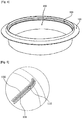
- FIG. 4 is a perspective view illustrating an assembled cooker according to the present invention
- FIG. 5 is a partial perspective view illustrating an example of ribs and a ventilation hole provided in the bottom of a main body.
- a metallic pan 200 is installed in a main body 100 through which microwaves are transmitted, a heating sheet 300 receiving the microwaves and generating heat is provided on an undersurface of the pan 200, and an insulating support 400 is provided below the heating sheet 300.
- Airtight coupling between the pan 200 and the main body 100 is implemented by a silicone packing 500 having inherent elasticity.
- a silicone packing 500 having inherent elasticity.
- the inherently elastic silicone packing 500 is decoupled from a packing groove 120 of the main body 100, thereby reducing the pressure.
- the main body 100 may be of one of a diversity of shapes such as a circle, a rectangle, etc., and has the continuous packing groove 120 on an upper inner surface thereof in order to receive the silicone packing 500.
- the silicone packing 500 is shaped like a ring corresponding to the shape of the main body 100, and is provided with an inner circumferential groove 510, in which the circumference 210 of the pan is inserted, and an outer upper, wedge-type protrusion 520 which is fixedly fitted into the packing groove 120 provided in the main body 100.
- the packing groove 120 of the main body 100 may be of a shape similar to a ' ⁇ ' type and receives therein the protrusion 520 and the lower portion of the silicone packing 500 so as to couple the silicone packing.
- the silicone packing 500 Since the silicone packing 500 has inherent elasticity, when the silicone packing 500 is coupled with the pan such that the circumferential groove 510 is inserted onto the circumference 210 of the pan, and then pushed into the main body 100, it is moved in a compressed state downwards along the inner surface and is coupled into the packing groove 120 of the main body. That is, when the compressed silicone packing 500 arrives at the packing groove 120, the silicone packing expands to its original shape and is brought into close contact at the protrusion 520 with the packing groove 120, forming a coupled state.
- the silicone packing 500 is further provided with a contact rib 530 on the upper portion thereof in order to come into close contact with the inner surface of the main body, which is continuous with the packing groove 120, thereby enhancing the airtightness thereof.
- the contact rib 530 is provided for sealing a gap between the main body and the silicone packing and comes into contact with the inner surface of the main body 100, so that upon cooking, moisture or food waste is prevented from entering the packing groove 120 of the main body.
- the heating sheet 300 provided below the pan 200 is a heating element for receiving microwaves and generating heat, but this element is a known element so its detailed description will be omitted.
- the insulating support 400 provided below the heating sheet 300 is composed of an inherently elastic ceramic wool material, so that after assembly, if pressure is applied from the topside, the inherently elastic insulating support 400 generates repulsive force upwards so as to support the heating sheet 300 and the pan 200 upwards within a certain range, whereby the silicone packing 500 inserted into the packing groove 120 maintains its fixation without being loosened vertically.
- the inherently elastic silicone packing 500 may be of a hardness of 30 to 80 degrees, preferably, and the hardness can be properly selected according to the size of the main body and the cooking use.
- the silicone packing 500 is an electrically nonconductive member and thus serves to prevent electromagnetic waves flowing through the metallic pan 200 via microwave transmission from transmitting to the main body 100, whereby a sparking occurring in the metallic pan 200 due to the microwaves can be advantageously prevented from occurring.
- One or more ventilation holes 110 are provided in the bottom of the main body 100 to provide pressure reduction. According to the present invention, a unique structure is employed in order to prevent the ventilation hole 110 from being clogged by the insulating support 400 provided on the bottom of the main body 100.
- the unique structure is configured such that two or more ribs 130 are provided on the bottom or a section extending from the bottom to a portion of the inner side surface of the main body 100, a space between the ribs 130 is defined as a ventilation passage 131, and the ventilation hole 110 is provided on a point along the ventilation passage 131.
- a structure including the ventilation passage 131, the ventilation hole 110, and the ribs 130 may be provided as one or more sets on the bottom, and if provided as two or more sets, they may be preferably provided in a symmetrical form.
- the insulating support 400 cannot clog the ventilation passage 131 and the ventilation hole 110, so that even if the internal pressure of the space C defined by the sides of the main body 100 and the pan 200 rises, high pressure air effectively exits via the ventilation passage 131 and the ventilation hole 110. At the same time, moisture permeated via the ventilation hole upon washing can also be naturally drained.
- the assembly when the pan 200 coupled with the silicon packing 500 is assembled with the main body 100, the assembly can be implemented while pressing with a dedicated pressing device, so that as compared to the conventional silicone-bonding method or inserting-method, the assembly is easy thereby improving productivity.
- the cooker is placed in a microwave oven and the oven is operated in the state in which a user does not check whether the ventilation hole 110 provided in the bottom of the main body 100 is clogged or not, high temperature heat is generated by the heating sheet 300 and thus air in the space C between the main body 100 and the pan 200 expands to cause an abrupt increase in internal pressure.
- the decoupling is implemented not on the whole of the silicone packing 500, but on a portion thereof, and the pressure reduction will be conducted via that portion, making the pressure reduction smooth.
- the pressure reduction via the ventilation hole 110 is not sufficient, the silicone packing 500 can be decoupled from the packing groove for secondary pressure reduction.
- Test 1 Explosion test of the main body
- the ventilation holes of the objective three cookers (1), (2), and (3) were clogged forcefully under the same conditions and method. (That is, the ventilation holes of the cookers were clogged, assuming that they may be clogged with food waste or the like by a user's carelessness)
- 250ml water was poured into the pans of the cookers (1), (2), and (3), and the cookers were heated for 10 to 15 minutes using a microwave oven.
- the prior art cookers (1) and (2) were blown up with the explosion in the microwave oven, and a glass plate of the oven, the main body and the pan were broken.
- the present cooker (3) was not blown up, and the silicone packing was partially decoupled from the main body due to the internal pressure of the space, so that there was no occurrence of damage in the product and the microwave oven.
- 250ml water was poured into the pans of the cookers (1) and (2), and the cookers were heated for 20 to 30 minutes using a microwave oven.
- the cooker of the present invention has excellent safety and is expected to be widely used as a cooker for a microwave oven while replacing existing products, providing very high availability.
Landscapes
- Physics & Mathematics (AREA)
- Electromagnetism (AREA)
- Engineering & Computer Science (AREA)
- Food Science & Technology (AREA)
- Cookers (AREA)
- Electric Ovens (AREA)
- Electric Stoves And Ranges (AREA)
Description
- The present invention relates to a microwave oven cooker for cooking food using heat from a heating element and in which a pan, a heating sheet, and an insulating support are closely coupled to a main body.
- A cooker for a microwave oven in which a pan, a heating sheet, and an insulating support are laminated on one another in a main body has been known in the art. The coupling between the pan and the main body was carried out in the following manner.
- That is, the pan can be bonded onto a portion of an upper surface of the main body with silicone adhesive or the like, or otherwise the pan can be inserted at the circumference into an inner surface of the main body.
- However, the silicone-bonding method had problems in that bonding and curing take a long time, hence lowering productivity, and because if the temperature of the pan exceeds a heat-resisting temperature limit of the silicone adhesive (260°C) the silicone adhesive loses its adhesive property, and further because of direct heat transfer of the pan to the main body, the main body can be thermally damaged and sparks can occur.
- Further, the inserting-coupling method also had problems such as the occurrence of thermal damage and sparks between the main body and the pan upon generating of high temperature heat.
- As an example, a heat generate cooker for microwave is known from
KR 2005 0080036 A - Above all, known prior technologies had problems in that if a microwave oven is operated with a ventilation hole provided in the bottom of the main body of a cooker being clogged or closed, due to a user's carelessness, internal pressure in the main body increases and it causes an explosion of the main body, thereby damaging the microwave oven and the user's safety as well.
- That is, while in the normal state, if the pressure of the main body rises sharply, pressure reduction will be performed by ventilation through the ventilation hole, but if the ventilation hole is clogged or closed off because of food remains or foreign material which are there due to carelessness of use and maintenance, an explosion may occur.
- The present invention has been made to solve the foregoing problems with the prior art, and therefore an object of the present invention is to provide a heating cooker for a microwave oven equipped with a safety device of a structure, which, even when a ventilation hole is closed, enables pressure reduction to occur before it builds up enough to cause an explosion, and more evidently promotes implementing the pressure reduction via the ventilation hole as well.
- The present invention provides a heating cooker for a microwave oven having the technical features as stated in the independent claim. Preferred embodiments of the present invention are featured in the dependent claims.
- In order to accomplish the above object of the present invention, according to an aspect of the present invention, there is provided a heating cooker for a microwave oven in which in a main body through which microwaves are transmitted, an upper portion of a metallic pan is closely coupled, and a heating sheet receiving the microwaves and generating heat and an insulating support are coupled in order onto an undersurface of the pan, the heating cooker including a safety device configured such that a silicone packing is provided in a section of the close coupling between the pan and the main body, and if the internal pressure of the cooker arises abnormally, the silicone packing is decoupled from the main body so as to reduce the pressure. This silicone packing is provided with an inner circumferential groove, into which the circumference of the pan is inserted, and an outer upper, wedge-type protrusion which is fixedly fitted into a packing groove provided in the main body.
- In an embodiment, the silicone packing may be further provided with a contact rib protruding from an upper surface thereof so as to come into close contact with an inner surface of the main body.
- In an embodiment, the insulating support may be composed of a self-elastic ceramic wool material so that if pressure is applied from upside, it elastically supports the heating sheet and the pan upward.
- In an embodiment, the main body may be provided with two or more ribs each protruding from the bottom thereof, and a ventilation hole communicating with outside is provided in a region between the ribs.
- According to the construction as set forth above, the heating cooker for a microwave oven of the present invention provides the effects of, even if the ventilation hole of the main body is clogged so that internal pressure rises abnormally, a pressure reduction being implemented before leading to an explosion, whereby an accident can be prevented from occurring and a loss of property due to the explosion can be avoided.
-
-
FIG. 1 is a schematic cross-sectional view illustrating a cooker according to the present invention; -
FIG. 2 is an enlarged cross-sectional view of a section A illustrated inFIG. 1 ; -
FIG. 3 is a cross-sectional view illustrating a silicone packing; -
FIG. 4 is a perspective view illustrating an assembled cooker according to the present invention; and -
FIG. 5 is a partial perspective view illustrating an example of ribs and a ventilation hole provided in the bottom of a main body. -
100: Main Body 110: Ventilation Hole 120: Packing Groove 130: Rib 131: Ventilation Passage 200: Pan 210: Circumference 300: Heating Sheet 400: Insulating Support 500: Silicone packing 510: Circumferential Groove 520: Protrusion 530: Contact Rib - Description will now be made of exemplary embodiments of the present invention with reference to the accompanying drawings as a means for assisting the understanding of the present invention. However, since the given figures only illustrate preferred embodiments of the present invention, it should be understood that modified embodiments, e.g. simple structural changes, are included within the technical scope of the present invention.
- Basically, according to the present invention, a heating cooker (hereinafter referred to as a 'cooker') for a microwave oven having a safety device includes a concave main body, a concave pan provided in the main body, and a planar heating sheet and an insulating support both provided between an upper surface of the bottom of the main body and a lower surface of the bottom of the pan. An empty space is provided between the main body and a side of the pan, and a silicone packing is used for connecting the pan and the main body.
- The silicone packing is installed so as to be connected with an upper circumference of the pan and an inner packing groove of the main body, making an airtight seal between the pan and the main body. According to the present invention, the silicone packing is characterized in that if internal pressure of the empty space rises abnormally, it is decoupled from the packing groove, reducing the pressure.
- Further, the present invention is also characterized in that the main body is provided with a plurality of ribs each protruding from the bottom thereof or a portion of the bottom and the side thereof so as to form a ventilation passage, and with a ventilation hole which communicates with the outside and is provided between the ribs so as to allow smooth pressure reduction therethrough.
- Preferred embodiments will now be described in detail while referring to the accompanying drawings, wherein
FIG. 1 is a schematic cross-sectional view illustrating a cooker according to the present invention,FIG. 2 is an enlarged cross-sectional view of a section A illustrated inFIG. 1, FIG. 3 is a cross-sectional view illustrating the silicone packing,FIG. 4 is a perspective view illustrating an assembled cooker according to the present invention, andFIG. 5 is a partial perspective view illustrating an example of ribs and a ventilation hole provided in the bottom of a main body. - As illustrated in the figures, a
metallic pan 200 is installed in amain body 100 through which microwaves are transmitted, aheating sheet 300 receiving the microwaves and generating heat is provided on an undersurface of thepan 200, and aninsulating support 400 is provided below theheating sheet 300. - Airtight coupling between the
pan 200 and themain body 100 is implemented by a silicone packing 500 having inherent elasticity. In the state in which aventilation hole 110 provided in the bottom of themain body 100 is clogged by the user's carelessness or the like, and if the cooker is operated and the internal pressure rises sharply, the inherentlyelastic silicone packing 500 is decoupled from apacking groove 120 of themain body 100, thereby reducing the pressure. - The
main body 100 may be of one of a diversity of shapes such as a circle, a rectangle, etc., and has thecontinuous packing groove 120 on an upper inner surface thereof in order to receive thesilicone packing 500. Thesilicone packing 500 is shaped like a ring corresponding to the shape of themain body 100, and is provided with an innercircumferential groove 510, in which thecircumference 210 of the pan is inserted, and an outer upper, wedge-type protrusion 520 which is fixedly fitted into thepacking groove 120 provided in themain body 100. - The
packing groove 120 of themain body 100 may be of a shape similar to a '⊂' type and receives therein theprotrusion 520 and the lower portion of the silicone packing 500 so as to couple the silicone packing. - Since the
silicone packing 500 has inherent elasticity, when thesilicone packing 500 is coupled with the pan such that thecircumferential groove 510 is inserted onto thecircumference 210 of the pan, and then pushed into themain body 100, it is moved in a compressed state downwards along the inner surface and is coupled into thepacking groove 120 of the main body. That is, when thecompressed silicone packing 500 arrives at thepacking groove 120, the silicone packing expands to its original shape and is brought into close contact at theprotrusion 520 with thepacking groove 120, forming a coupled state. - More preferably, the
silicone packing 500 is further provided with acontact rib 530 on the upper portion thereof in order to come into close contact with the inner surface of the main body, which is continuous with thepacking groove 120, thereby enhancing the airtightness thereof. Thecontact rib 530 is provided for sealing a gap between the main body and the silicone packing and comes into contact with the inner surface of themain body 100, so that upon cooking, moisture or food waste is prevented from entering thepacking groove 120 of the main body. - The
heating sheet 300 provided below thepan 200 is a heating element for receiving microwaves and generating heat, but this element is a known element so its detailed description will be omitted. - The
insulating support 400 provided below theheating sheet 300 is composed of an inherently elastic ceramic wool material, so that after assembly, if pressure is applied from the topside, the inherently elasticinsulating support 400 generates repulsive force upwards so as to support theheating sheet 300 and thepan 200 upwards within a certain range, whereby thesilicone packing 500 inserted into thepacking groove 120 maintains its fixation without being loosened vertically. - Meanwhile, the inherently elastic silicone packing 500 may be of a hardness of 30 to 80 degrees, preferably, and the hardness can be properly selected according to the size of the main body and the cooking use.
- Further, the
silicone packing 500 is an electrically nonconductive member and thus serves to prevent electromagnetic waves flowing through themetallic pan 200 via microwave transmission from transmitting to themain body 100, whereby a sparking occurring in themetallic pan 200 due to the microwaves can be advantageously prevented from occurring. - One or
more ventilation holes 110 are provided in the bottom of themain body 100 to provide pressure reduction. According to the present invention, a unique structure is employed in order to prevent theventilation hole 110 from being clogged by theinsulating support 400 provided on the bottom of themain body 100. - That is, the unique structure is configured such that two or
more ribs 130 are provided on the bottom or a section extending from the bottom to a portion of the inner side surface of themain body 100, a space between theribs 130 is defined as aventilation passage 131, and theventilation hole 110 is provided on a point along theventilation passage 131. Such a structure including theventilation passage 131, theventilation hole 110, and theribs 130 may be provided as one or more sets on the bottom, and if provided as two or more sets, they may be preferably provided in a symmetrical form. - Providing the plurality of
ribs 130 on the bottom of themain body 100, theinsulating support 400 cannot clog theventilation passage 131 and theventilation hole 110, so that even if the internal pressure of the space C defined by the sides of themain body 100 and thepan 200 rises, high pressure air effectively exits via theventilation passage 131 and theventilation hole 110. At the same time, moisture permeated via the ventilation hole upon washing can also be naturally drained. - Further, according to the present invention, when the
pan 200 coupled with thesilicon packing 500 is assembled with themain body 100, the assembly can be implemented while pressing with a dedicated pressing device, so that as compared to the conventional silicone-bonding method or inserting-method, the assembly is easy thereby improving productivity. - The operating principle of the present cooker will now be described.
- If the cooker is placed in a microwave oven and the oven is operated in the state in which a user does not check whether the
ventilation hole 110 provided in the bottom of themain body 100 is clogged or not, high temperature heat is generated by theheating sheet 300 and thus air in the space C between themain body 100 and thepan 200 expands to cause an abrupt increase in internal pressure. - If the internal pressure of the space C exceeds a threshold value, a portion of the
silicone packing 500 coupled with thepacking groove 120 becomes decoupled from thepacking groove 120 due to internal pressure, reducing the internal pressure and thus preventing the occurrence of an explosion. At this time, the decoupling is implemented not on the whole of thesilicone packing 500, but on a portion thereof, and the pressure reduction will be conducted via that portion, making the pressure reduction smooth. - Then, even if the silicone packing 500 is decoupled from the packing groove for pressure reduction, a user can push again and insert the silicone packing 500 into the packing
groove 120 so as to implement re-coupling, so that it can be continuously used without buying it again. - Further, providing the
ventilation passage 131 on the bottom of themain body 100 using the plurality ofribs 130, and providing theventilation hole 110 in theventilation passage 131, even upon formation of high pressure in the space C, a ventilation path of the high pressure air is secured via theventilation hole 110 through theventilation passage 131 defined by theribs 130, whereby primary pressure reduction is obtained via theventilation hole 110, which avoids making efforts to re-couple the silicone packing 500 with the packinggroove 120, which have been decoupled. Of course, if the pressure reduction via theventilation hole 110 is not sufficient, the silicone packing 500 can be decoupled from the packing groove for secondary pressure reduction. - Comparative test examples on pressure reduction characteristics using the cookers will now be described.
- A test was carried out on objective samples of cookers in order to investigate the explosion of the main body and the ventilation effects of the expended air.
-
- (1) Silicone-bonding type cooker for a microwave oven (prior art), in which the coupling between the main body and the circumference of the pan is of a silicone-bonding method.
- (2) Inserting-coupling type cooker for a microwave oven (prior art) in which the coupling between the main body and the circumference of the pan is of an inserting-coupling method.
- (3) Silicone packing structure cooker for a microwave oven (present invention).
- In the test, the ventilation holes of the objective three cookers (1), (2), and (3) were clogged forcefully under the same conditions and method.
(That is, the ventilation holes of the cookers were clogged, assuming that they may be clogged with food waste or the like by a user's carelessness) - 250ml water was poured into the pans of the cookers (1), (2), and (3), and the cookers were heated for 10 to 15 minutes using a microwave oven.
- The microwave oven: a rated RF power of 700W
- The prior art cookers (1) and (2) were blown up with the explosion in the microwave oven, and a glass plate of the oven, the main body and the pan were broken.
However, the present cooker (3) was not blown up, and the silicone packing was partially decoupled from the main body due to the internal pressure of the space, so that there was no occurrence of damage in the product and the microwave oven. - The reason that a time to explosion ranged from between 10 minutes and 15 minutes and was not constant was because the time depended on the heat generating power of the heating sheet, and as the heating sheet had higher performance (i.e., higher heat generating power), the time to explosion became shortened.
-
- (1) Comparative cooker with a silicone packing in which a rib and a ventilation passage 24 are not provided on the bottom of the main body, but only a ventilation hole 23 is punctured in the bottom.
- (2) Present cooker with a silicone packing 1 in which a rib, a ventilation passage and a ventilation hole are provided on the bottom of the main body.
- The insulating supports used in those cookers (1) and (2) were prepared in a state of being intentionally wet and stained with oil (because they are used in a cooker and therefore are usually used in a state of being wet and stained with oil due to the user's carelessness during cooking).
- 250ml water was poured into the pans of the cookers (1) and (2), and the cookers were heated for 20 to 30 minutes using a microwave oven.
- The microwave oven: a rated RF power of 700W
- In the case of the cooker (1), although the ventilation hole was provided, moisture and oil stain hindered ventilation through the insulating support of ceramic wool material, so that the expanded air was not completely (100%) vented, and the space was thermally expanded by the internal pressure, whereby the silicone packing was decoupled from the main body.
- However, in the present cooker (2), although moisture and oil stain hindered the ventilation of the insulating support of the ceramic wool material, 100% of the expanded air was completely vented, so that the space was not thermally expanded and thus the silicone packing 1 was not decoupled from the main body 2.
- It was verified that the present cooker having the silicone packing 1 and the ventilation hole 23 with the ventilation passage 24 is of the safest structure and does not cause explosion and decoupling of the silicone packing.
- The cooker of the present invention has excellent safety and is expected to be widely used as a cooker for a microwave oven while replacing existing products, providing very high availability.
Claims (4)
- A heating cooker for a microwave oven having a main body (100) through which microwaves are transmitted, an upper portion of a metallic pan (200) coupled to the main body (100) by means of an airtight seal between the main body (100) and the pan (200), wherein a heating sheet (300) receiving the microwaves and generating heat and an insulating support (400) are coupled onto an undersurface of the pan (200),
the heating cooker characterized by a silicone packing (500) provided in a section of the airtight seal between the pan (200) and the main body (100), so that if internal pressure in an empty space (C) between the main body (100) and a side of the pan (200) rises abnormally the silicone packing (500) is decoupled from the main body (100) so as to reduce the pressure, wherein the silicone packing (500) is provided with (a) an inner circumferential groove (510), into which a circumference of the pan (200) is inserted, and (b) an outer upper, wedge-type protrusion (520) which is fixedly fitted into a packing groove (120) provided in the main body (100). - The heating cooker for a microwave oven according to claim 1, wherein the silicone packing (500) is further provided with a contact rib (530) protruding from an upper surface thereof so as to come into close contact with an inner surface of the main body (100).
- The heating cooker for a microwave oven according to claim 1 or 2, wherein the insulating support (400) is composed of an inherently elastic ceramic wool material so that if pressure is applied from topside, it elastically supports the heating sheet (300) and the pan (200) upwards.
- The heating cooker for a microwave oven according to claim 3, wherein the main body (100) is provided with two or more ribs (130) each protruding from a bottom thereof, and a ventilation hole (110) communicating with outside is provided in a region between the ribs (130) .
Applications Claiming Priority (1)
| Application Number | Priority Date | Filing Date | Title |
|---|---|---|---|
| PCT/KR2009/000642 WO2010093068A1 (en) | 2009-02-11 | 2009-02-11 | Heating cooker with safety device for microwave oven |
Publications (3)
| Publication Number | Publication Date |
|---|---|
| EP2397772A1 EP2397772A1 (en) | 2011-12-21 |
| EP2397772A4 EP2397772A4 (en) | 2014-12-17 |
| EP2397772B1 true EP2397772B1 (en) | 2018-10-03 |
Family
ID=42561903
Family Applications (1)
| Application Number | Title | Priority Date | Filing Date |
|---|---|---|---|
| EP09829859.9A Active EP2397772B1 (en) | 2009-02-11 | 2009-02-11 | Heating cooker with safety device for microwave oven |
Country Status (5)
| Country | Link |
|---|---|
| US (1) | US10231291B2 (en) |
| EP (1) | EP2397772B1 (en) |
| JP (1) | JP5344638B2 (en) |
| CN (1) | CN101960224B (en) |
| WO (1) | WO2010093068A1 (en) |
Families Citing this family (14)
| Publication number | Priority date | Publication date | Assignee | Title |
|---|---|---|---|---|
| US10098190B2 (en) * | 2010-10-07 | 2018-10-09 | Jong Peter Park | Microwaveable vessel |
| US20150313398A1 (en) * | 2013-05-02 | 2015-11-05 | Jong Peter Park | Thermodynamic energy-saving health cookware |
| US20170150840A1 (en) * | 2010-11-03 | 2017-06-01 | Jong Peter Park | Multi-purpose double layered container |
| CN102846184A (en) * | 2012-09-25 | 2013-01-02 | 宾梦 | Salient point cooker |
| US9538776B2 (en) * | 2013-04-27 | 2017-01-10 | KitchenTek, LLC | Pressurized oven assembly |
| CN106797682B (en) * | 2014-07-08 | 2020-08-07 | 朴钟道 | Container for microwave oven |
| US10722070B2 (en) * | 2015-06-14 | 2020-07-28 | Jong Peter Park | Multi-layered exothermic microwave cookware |
| CN205037382U (en) * | 2015-09-14 | 2016-02-17 | 佛山市顺德区汉蒲电器科技有限公司 | Removable microwave ovenware of modified |
| US20180086536A1 (en) * | 2016-09-23 | 2018-03-29 | Michel Cabiran | Ring to Space Plates In Microwave Oven |
| CN110200516A (en) | 2017-08-09 | 2019-09-06 | 沙克忍者运营有限责任公司 | Cooking system |
| WO2020176477A1 (en) | 2019-02-25 | 2020-09-03 | Sharkninja Operating Llc | Cooking system with guard |
| US11647861B2 (en) | 2020-03-30 | 2023-05-16 | Sharkninja Operating Llc | Cooking device and components thereof |
| WO2021253051A1 (en) * | 2020-06-11 | 2021-12-16 | Ovention, Inc. | Systems and methods for cookware having heat conductive elements, and an oven utilizing the cookware |
| KR102932501B1 (en) * | 2020-10-19 | 2026-02-26 | 엘지전자 주식회사 | Cooking appliance |
Family Cites Families (61)
| Publication number | Priority date | Publication date | Assignee | Title |
|---|---|---|---|---|
| US1499364A (en) * | 1924-07-01 | Cooking vessel | ||
| US2367409A (en) * | 1944-01-21 | 1945-01-16 | Otto A Kuhler | Interlock |
| US2600714A (en) * | 1946-05-18 | 1952-06-17 | Speed Meal Corp | Gasket for pressure cookers |
| US2552642A (en) * | 1947-08-15 | 1951-05-15 | West Bend Aluminum Co | Safety pressure release for pressure cookers |
| US2545733A (en) * | 1948-11-30 | 1951-03-20 | Edgar A Elkins | Child's hot food dish |
| US2829796A (en) * | 1953-10-31 | 1958-04-08 | Dieny Alfred | Tight closing device for internal pressure vessels |
| US2771754A (en) * | 1954-05-27 | 1956-11-27 | Winkler Gilbert | Dishes or plates |
| US3934748A (en) * | 1972-04-10 | 1976-01-27 | Racz Nick S | Cookware containers |
| US3941967A (en) * | 1973-09-28 | 1976-03-02 | Asahi Kasei Kogyo Kabushiki Kaisha | Microwave cooking apparatus |
| BR5701390U (en) * | 1977-11-04 | 1979-06-19 | M Chiodo | PRESSURE POT PERFECTING |
| US4306133A (en) * | 1979-02-14 | 1981-12-15 | Levinson Melvin L | Microwave pie baking |
| US4496815A (en) * | 1983-01-14 | 1985-01-29 | Northland Aluminum Products, Inc. | Microwave browning utensil |
| BR8305177A (en) * | 1983-09-22 | 1985-04-30 | Alcan Brasil | PRESSURE POT PERFECTING |
| US4542271A (en) * | 1984-10-05 | 1985-09-17 | Rubbermaid Incorporated | Microwave browning wares and method for the manufacture thereof |
| US4701585A (en) * | 1986-04-04 | 1987-10-20 | Kidde Consumer Durables Corp. | Microwave browning cookware |
| JPH0451743Y2 (en) * | 1986-07-04 | 1992-12-04 | ||
| JP2714828B2 (en) * | 1987-11-27 | 1998-02-16 | 恭子 溝口 | Microwave oven container |
| JPH0417085Y2 (en) * | 1987-12-09 | 1992-04-16 | ||
| JPH01167532A (en) * | 1987-12-21 | 1989-07-03 | Sharp Corp | Heat generating body for microwave oven |
| US4870233A (en) * | 1988-09-19 | 1989-09-26 | General Mills, Inc. | Metal tray and susceptor combination for use in microwave ovens |
| US5239153A (en) * | 1988-11-28 | 1993-08-24 | Beckett Industries Inc. | Differential thermal heating in microwave oven packages |
| JPH02180218A (en) * | 1988-12-31 | 1990-07-13 | Kyoko Mizoguchi | Pressure container for microwave oven |
| JP3099015B2 (en) * | 1988-12-31 | 2000-10-16 | 恭子 溝口 | Microwave oven container |
| JPH0667343B2 (en) * | 1988-12-31 | 1994-08-31 | 恭子 溝口 | Pressure regulator for microwave oven container |
| US5121852A (en) * | 1990-05-23 | 1992-06-16 | Essef Corporation | Dynamic pressure relief seal for pressure vessels |
| JPH0521155A (en) * | 1991-01-18 | 1993-01-29 | Jae C Choi | Pan for electronic oven |
| CA2130080C (en) * | 1991-02-18 | 1996-05-21 | Melvin L. Levinson | Two-stage process for cooking/browning/crusting food by microwave energy and infrared energy |
| JP3126230B2 (en) * | 1992-08-21 | 2001-01-22 | 三菱製紙株式会社 | Method for producing diazo photosensitive paper base paper |
| US5387781A (en) * | 1992-11-09 | 1995-02-07 | Berkoff; William | Vented food cooking system for microwave ovens |
| DE4239552C1 (en) * | 1992-11-25 | 1994-04-28 | Karl Niese | Pressure cooker |
| FR2720465B1 (en) * | 1994-05-27 | 1996-07-26 | Seb Sa | Safety device for a pressure vessel comprising a weak section seal. |
| US5586487A (en) * | 1995-05-22 | 1996-12-24 | Marino; Francis E. | Pasta percolator |
| US5558798A (en) * | 1995-06-12 | 1996-09-24 | Tsai; Daniel T. | Microwave steam cooking apparatus |
| DE19746845C1 (en) * | 1997-10-23 | 1998-12-03 | Schott Glas | Ceramic heating element for electric cooking hob |
| FR2782257B1 (en) * | 1998-08-13 | 2000-11-17 | Seb Sa | INDEX SEAL FOR A PRESSURE COOKER, AND A PRESSURE COOKER HAVING SUCH A SEAL |
| JP2002034785A (en) * | 2000-07-21 | 2002-02-05 | Chubu Electric Power Co Inc | Pot for induction cooking |
| JP2002305157A (en) * | 2000-12-28 | 2002-10-18 | Tokyo Electron Ltd | Honeycomb structure heat insulator and heat reuse system |
| US6705210B2 (en) * | 2001-03-20 | 2004-03-16 | Joseph L. Leonard | Chafing dish with utility handles |
| JP3533193B2 (en) * | 2001-05-14 | 2004-05-31 | 株式会社よこやま | pot |
| DE10132899C1 (en) * | 2001-07-06 | 2003-02-06 | Schott Glas | Cooking area with a glass ceramic bowl with a lowered, curved heating surface |
| DE20113356U1 (en) * | 2001-08-10 | 2002-12-19 | Synkrona Ag, Stans | Closing device for a container |
| US6526875B1 (en) * | 2001-08-27 | 2003-03-04 | DuWayne Dzibinski | Cooking vessel with removable trough |
| JP2003081313A (en) * | 2001-09-13 | 2003-03-19 | Edogawa Bussan Kk | Container for food |
| US20040089160A1 (en) * | 2002-11-07 | 2004-05-13 | Doundoulakis George J. | Ever-clean compound utensil |
| US6747250B1 (en) * | 2003-01-10 | 2004-06-08 | Morning Electronics Co. Ltd. | Counter-top electric oven |
| US7038181B2 (en) * | 2003-05-21 | 2006-05-02 | Megadex Corporation | Microwave beverage and food preparation apparatus |
| FR2862853B1 (en) * | 2003-11-27 | 2006-09-15 | Seb Sa | PRESSURIZED COOKING APPARATUS PROVIDED WITH A SAFETY DEVICE AT THE OVERPRESSURE, AND SEALING SEAL FOR SUCH AN APPARATUS |
| WO2005084253A2 (en) * | 2004-03-02 | 2005-09-15 | M Management-Tex, Ltd. | Cooktop gasket |
| US20050199636A1 (en) * | 2004-03-09 | 2005-09-15 | I-Wen Liu | Silicone-rubber plate used in an oven |
| US7256374B2 (en) * | 2004-05-17 | 2007-08-14 | Colin Regan | Induction heating apparatus for controlling the welding parameter of temperature for heat treating a section of piping |
| MX2007001395A (en) * | 2004-08-06 | 2007-04-19 | Pactiv Corp | Microwaveable laminate container. |
| US7980171B2 (en) * | 2004-10-07 | 2011-07-19 | All-Clad Metalcrafters Llc | Vacuum cooking or warming appliance |
| KR100714053B1 (en) * | 2005-06-24 | 2007-05-04 | 김종현 | Heat generate cooker for microwave |
| US7614518B2 (en) * | 2005-04-08 | 2009-11-10 | Bradshaw International, Inc. | Holder for baked goods |
| JP2007031866A (en) * | 2005-07-25 | 2007-02-08 | Ibiden Co Ltd | Punched plate for holding sealing material of exhaust gas treatment body and method of manufacturing holding sealing material using the same |
| US20070084859A1 (en) * | 2005-09-30 | 2007-04-19 | Min-Ching Chen | Utensil for conventional heating and microwave heating |
| FR2922428A1 (en) * | 2007-10-23 | 2009-04-24 | Seb Sa | SELF-CLEANER WITH SAFETY OVERFLOW SYSTEM |
| US8124917B2 (en) * | 2008-05-02 | 2012-02-28 | Edgecraft Corporation | Accurate temperature measurement in household kettles |
| DE102008030077A1 (en) * | 2008-06-25 | 2009-12-31 | Fissler Gmbh | pressure vessel |
| KR100937534B1 (en) * | 2009-02-11 | 2010-02-11 | (주)펠리테크 | Generation of heat cooker for the microwave oven with a safety apparatus |
| US20100260900A1 (en) * | 2009-03-17 | 2010-10-14 | Sara Lee Corporation | Microwaveable product |
-
2009
- 2009-02-11 JP JP2010550587A patent/JP5344638B2/en active Active
- 2009-02-11 US US13/201,105 patent/US10231291B2/en active Active
- 2009-02-11 WO PCT/KR2009/000642 patent/WO2010093068A1/en not_active Ceased
- 2009-02-11 EP EP09829859.9A patent/EP2397772B1/en active Active
- 2009-02-11 CN CN2009801076081A patent/CN101960224B/en active Active
Non-Patent Citations (1)
| Title |
|---|
| None * |
Also Published As
| Publication number | Publication date |
|---|---|
| WO2010093068A1 (en) | 2010-08-19 |
| JP5344638B2 (en) | 2013-11-20 |
| JP2011511925A (en) | 2011-04-14 |
| US10231291B2 (en) | 2019-03-12 |
| CN101960224A (en) | 2011-01-26 |
| EP2397772A4 (en) | 2014-12-17 |
| EP2397772A1 (en) | 2011-12-21 |
| CN101960224B (en) | 2012-07-18 |
| US20120037617A1 (en) | 2012-02-16 |
Similar Documents
| Publication | Publication Date | Title |
|---|---|---|
| US10231291B2 (en) | Heating cooker with safety device for microwave oven | |
| US20030155365A1 (en) | Receptacle | |
| CN101352315A (en) | Pressure cooker equipped with a fixed gripping element on the tank | |
| CN107684336A (en) | The support member of electric pressure cooking saucepan and electric pressure cooking saucepan | |
| KR100937534B1 (en) | Generation of heat cooker for the microwave oven with a safety apparatus | |
| JPH01240475A (en) | Container for use in microwave oven | |
| KR101849762B1 (en) | cover packing for reinforcing pressure support | |
| JP5653381B2 (en) | Rice cooker and cooking device provided with the same | |
| AU2017312404A1 (en) | Pressing element and induction hob comprising a pressing element | |
| CN210961469U (en) | Low-cost electric pressure cooker | |
| CN107669136B (en) | Movable cover plate assembly, upper cover structure of electric rice cooker and electric rice cooker | |
| CN110507167B (en) | Float valve subassembly, cooking utensil's lid assembly and cooking utensil | |
| KR20120015100A (en) | Hermetic microwave | |
| CN211242826U (en) | Electromagnetic heating electric pressure cooker | |
| CN210961476U (en) | Electromagnetic heating electric pressure cooker | |
| CN211270000U (en) | Electromagnetic heating electric pressure cooker | |
| KR20180009161A (en) | Lid of inner pot for Electric pressure cooker | |
| CN210961477U (en) | Electromagnetic heating electric pressure cooker | |
| JP5826356B2 (en) | Rice cooker and cooking device provided with the same | |
| CN223695562U (en) | Cover assembly and cooking utensils having it | |
| CN210961470U (en) | Electromagnetic heating electric pressure cooker | |
| CN112294107B (en) | Electromagnetic heating electric pressure cooker | |
| KR100827406B1 (en) | Non-return type steam discharge device of electric pressure thermostat rice cooker | |
| CN213371345U (en) | Pottery pot subassembly and electric stewpan | |
| KR102342276B1 (en) | Dual layer cooking receptacle with increased induction structure |
Legal Events
| Date | Code | Title | Description |
|---|---|---|---|
| PUAI | Public reference made under article 153(3) epc to a published international application that has entered the european phase |
Free format text: ORIGINAL CODE: 0009012 |
|
| 17P | Request for examination filed |
Effective date: 20101224 |
|
| AK | Designated contracting states |
Kind code of ref document: A1 Designated state(s): AT BE BG CH CY CZ DE DK EE ES FI FR GB GR HR HU IE IS IT LI LT LU LV MC MK MT NL NO PL PT RO SE SI SK TR |
|
| DAX | Request for extension of the european patent (deleted) | ||
| A4 | Supplementary search report drawn up and despatched |
Effective date: 20141117 |
|
| RIC1 | Information provided on ipc code assigned before grant |
Ipc: A47J 36/02 20060101ALI20141111BHEP Ipc: H05B 6/64 20060101AFI20141111BHEP Ipc: A47J 27/088 20060101ALI20141111BHEP |
|
| REG | Reference to a national code |
Ref country code: DE Ref legal event code: R079 Ref document number: 602009054900 Country of ref document: DE Free format text: PREVIOUS MAIN CLASS: F24C0015000000 Ipc: H05B0006640000 |
|
| GRAP | Despatch of communication of intention to grant a patent |
Free format text: ORIGINAL CODE: EPIDOSNIGR1 |
|
| STAA | Information on the status of an ep patent application or granted ep patent |
Free format text: STATUS: GRANT OF PATENT IS INTENDED |
|
| RIC1 | Information provided on ipc code assigned before grant |
Ipc: A47J 36/02 20060101ALI20171115BHEP Ipc: H05B 6/64 20060101AFI20171115BHEP Ipc: A47J 27/088 20060101ALI20171115BHEP |
|
| INTG | Intention to grant announced |
Effective date: 20171207 |
|
| GRAS | Grant fee paid |
Free format text: ORIGINAL CODE: EPIDOSNIGR3 |
|
| RAP1 | Party data changed (applicant data changed or rights of an application transferred) |
Owner name: PELLYTECH CO., LTD |
|
| GRAA | (expected) grant |
Free format text: ORIGINAL CODE: 0009210 |
|
| STAA | Information on the status of an ep patent application or granted ep patent |
Free format text: STATUS: THE PATENT HAS BEEN GRANTED |
|
| AK | Designated contracting states |
Kind code of ref document: B1 Designated state(s): AT BE BG CH CY CZ DE DK EE ES FI FR GB GR HR HU IE IS IT LI LT LU LV MC MK MT NL NO PL PT RO SE SI SK TR |
|
| REG | Reference to a national code |
Ref country code: GB Ref legal event code: FG4D |
|
| REG | Reference to a national code |
Ref country code: CH Ref legal event code: EP Ref country code: AT Ref legal event code: REF Ref document number: 1050105 Country of ref document: AT Kind code of ref document: T Effective date: 20181015 |
|
| REG | Reference to a national code |
Ref country code: DE Ref legal event code: R096 Ref document number: 602009054900 Country of ref document: DE |
|
| REG | Reference to a national code |
Ref country code: IE Ref legal event code: FG4D |
|
| REG | Reference to a national code |
Ref country code: NL Ref legal event code: MP Effective date: 20181003 |
|
| REG | Reference to a national code |
Ref country code: LT Ref legal event code: MG4D |
|
| REG | Reference to a national code |
Ref country code: AT Ref legal event code: MK05 Ref document number: 1050105 Country of ref document: AT Kind code of ref document: T Effective date: 20181003 |
|
| PG25 | Lapsed in a contracting state [announced via postgrant information from national office to epo] |
Ref country code: NL Free format text: LAPSE BECAUSE OF FAILURE TO SUBMIT A TRANSLATION OF THE DESCRIPTION OR TO PAY THE FEE WITHIN THE PRESCRIBED TIME-LIMIT Effective date: 20181003 |
|
| PG25 | Lapsed in a contracting state [announced via postgrant information from national office to epo] |
Ref country code: CZ Free format text: LAPSE BECAUSE OF FAILURE TO SUBMIT A TRANSLATION OF THE DESCRIPTION OR TO PAY THE FEE WITHIN THE PRESCRIBED TIME-LIMIT Effective date: 20181003 Ref country code: LV Free format text: LAPSE BECAUSE OF FAILURE TO SUBMIT A TRANSLATION OF THE DESCRIPTION OR TO PAY THE FEE WITHIN THE PRESCRIBED TIME-LIMIT Effective date: 20181003 Ref country code: HR Free format text: LAPSE BECAUSE OF FAILURE TO SUBMIT A TRANSLATION OF THE DESCRIPTION OR TO PAY THE FEE WITHIN THE PRESCRIBED TIME-LIMIT Effective date: 20181003 Ref country code: ES Free format text: LAPSE BECAUSE OF FAILURE TO SUBMIT A TRANSLATION OF THE DESCRIPTION OR TO PAY THE FEE WITHIN THE PRESCRIBED TIME-LIMIT Effective date: 20181003 Ref country code: PL Free format text: LAPSE BECAUSE OF FAILURE TO SUBMIT A TRANSLATION OF THE DESCRIPTION OR TO PAY THE FEE WITHIN THE PRESCRIBED TIME-LIMIT Effective date: 20181003 Ref country code: BG Free format text: LAPSE BECAUSE OF FAILURE TO SUBMIT A TRANSLATION OF THE DESCRIPTION OR TO PAY THE FEE WITHIN THE PRESCRIBED TIME-LIMIT Effective date: 20190103 Ref country code: LT Free format text: LAPSE BECAUSE OF FAILURE TO SUBMIT A TRANSLATION OF THE DESCRIPTION OR TO PAY THE FEE WITHIN THE PRESCRIBED TIME-LIMIT Effective date: 20181003 Ref country code: FI Free format text: LAPSE BECAUSE OF FAILURE TO SUBMIT A TRANSLATION OF THE DESCRIPTION OR TO PAY THE FEE WITHIN THE PRESCRIBED TIME-LIMIT Effective date: 20181003 Ref country code: NO Free format text: LAPSE BECAUSE OF FAILURE TO SUBMIT A TRANSLATION OF THE DESCRIPTION OR TO PAY THE FEE WITHIN THE PRESCRIBED TIME-LIMIT Effective date: 20190103 Ref country code: IS Free format text: LAPSE BECAUSE OF FAILURE TO SUBMIT A TRANSLATION OF THE DESCRIPTION OR TO PAY THE FEE WITHIN THE PRESCRIBED TIME-LIMIT Effective date: 20190203 Ref country code: AT Free format text: LAPSE BECAUSE OF FAILURE TO SUBMIT A TRANSLATION OF THE DESCRIPTION OR TO PAY THE FEE WITHIN THE PRESCRIBED TIME-LIMIT Effective date: 20181003 |
|
| PG25 | Lapsed in a contracting state [announced via postgrant information from national office to epo] |
Ref country code: SE Free format text: LAPSE BECAUSE OF FAILURE TO SUBMIT A TRANSLATION OF THE DESCRIPTION OR TO PAY THE FEE WITHIN THE PRESCRIBED TIME-LIMIT Effective date: 20181003 Ref country code: GR Free format text: LAPSE BECAUSE OF FAILURE TO SUBMIT A TRANSLATION OF THE DESCRIPTION OR TO PAY THE FEE WITHIN THE PRESCRIBED TIME-LIMIT Effective date: 20190104 Ref country code: PT Free format text: LAPSE BECAUSE OF FAILURE TO SUBMIT A TRANSLATION OF THE DESCRIPTION OR TO PAY THE FEE WITHIN THE PRESCRIBED TIME-LIMIT Effective date: 20190203 |
|
| REG | Reference to a national code |
Ref country code: DE Ref legal event code: R097 Ref document number: 602009054900 Country of ref document: DE |
|
| PG25 | Lapsed in a contracting state [announced via postgrant information from national office to epo] |
Ref country code: DK Free format text: LAPSE BECAUSE OF FAILURE TO SUBMIT A TRANSLATION OF THE DESCRIPTION OR TO PAY THE FEE WITHIN THE PRESCRIBED TIME-LIMIT Effective date: 20181003 |
|
| PLBE | No opposition filed within time limit |
Free format text: ORIGINAL CODE: 0009261 |
|
| STAA | Information on the status of an ep patent application or granted ep patent |
Free format text: STATUS: NO OPPOSITION FILED WITHIN TIME LIMIT |
|
| PG25 | Lapsed in a contracting state [announced via postgrant information from national office to epo] |
Ref country code: RO Free format text: LAPSE BECAUSE OF FAILURE TO SUBMIT A TRANSLATION OF THE DESCRIPTION OR TO PAY THE FEE WITHIN THE PRESCRIBED TIME-LIMIT Effective date: 20181003 Ref country code: SK Free format text: LAPSE BECAUSE OF FAILURE TO SUBMIT A TRANSLATION OF THE DESCRIPTION OR TO PAY THE FEE WITHIN THE PRESCRIBED TIME-LIMIT Effective date: 20181003 Ref country code: EE Free format text: LAPSE BECAUSE OF FAILURE TO SUBMIT A TRANSLATION OF THE DESCRIPTION OR TO PAY THE FEE WITHIN THE PRESCRIBED TIME-LIMIT Effective date: 20181003 |
|
| 26N | No opposition filed |
Effective date: 20190704 |
|
| REG | Reference to a national code |
Ref country code: CH Ref legal event code: PL |
|
| PG25 | Lapsed in a contracting state [announced via postgrant information from national office to epo] |
Ref country code: LU Free format text: LAPSE BECAUSE OF NON-PAYMENT OF DUE FEES Effective date: 20190211 Ref country code: SI Free format text: LAPSE BECAUSE OF FAILURE TO SUBMIT A TRANSLATION OF THE DESCRIPTION OR TO PAY THE FEE WITHIN THE PRESCRIBED TIME-LIMIT Effective date: 20181003 Ref country code: MC Free format text: LAPSE BECAUSE OF FAILURE TO SUBMIT A TRANSLATION OF THE DESCRIPTION OR TO PAY THE FEE WITHIN THE PRESCRIBED TIME-LIMIT Effective date: 20181003 |
|
| REG | Reference to a national code |
Ref country code: BE Ref legal event code: MM Effective date: 20190228 |
|
| REG | Reference to a national code |
Ref country code: IE Ref legal event code: MM4A |
|
| PG25 | Lapsed in a contracting state [announced via postgrant information from national office to epo] |
Ref country code: LI Free format text: LAPSE BECAUSE OF NON-PAYMENT OF DUE FEES Effective date: 20190228 Ref country code: CH Free format text: LAPSE BECAUSE OF NON-PAYMENT OF DUE FEES Effective date: 20190228 |
|
| PG25 | Lapsed in a contracting state [announced via postgrant information from national office to epo] |
Ref country code: IE Free format text: LAPSE BECAUSE OF NON-PAYMENT OF DUE FEES Effective date: 20190211 |
|
| PG25 | Lapsed in a contracting state [announced via postgrant information from national office to epo] |
Ref country code: BE Free format text: LAPSE BECAUSE OF NON-PAYMENT OF DUE FEES Effective date: 20190228 |
|
| PG25 | Lapsed in a contracting state [announced via postgrant information from national office to epo] |
Ref country code: TR Free format text: LAPSE BECAUSE OF FAILURE TO SUBMIT A TRANSLATION OF THE DESCRIPTION OR TO PAY THE FEE WITHIN THE PRESCRIBED TIME-LIMIT Effective date: 20181003 |
|
| PG25 | Lapsed in a contracting state [announced via postgrant information from national office to epo] |
Ref country code: MT Free format text: LAPSE BECAUSE OF NON-PAYMENT OF DUE FEES Effective date: 20190211 |
|
| PG25 | Lapsed in a contracting state [announced via postgrant information from national office to epo] |
Ref country code: CY Free format text: LAPSE BECAUSE OF FAILURE TO SUBMIT A TRANSLATION OF THE DESCRIPTION OR TO PAY THE FEE WITHIN THE PRESCRIBED TIME-LIMIT Effective date: 20181003 |
|
| PG25 | Lapsed in a contracting state [announced via postgrant information from national office to epo] |
Ref country code: HU Free format text: LAPSE BECAUSE OF FAILURE TO SUBMIT A TRANSLATION OF THE DESCRIPTION OR TO PAY THE FEE WITHIN THE PRESCRIBED TIME-LIMIT; INVALID AB INITIO Effective date: 20090211 |
|
| PG25 | Lapsed in a contracting state [announced via postgrant information from national office to epo] |
Ref country code: MK Free format text: LAPSE BECAUSE OF FAILURE TO SUBMIT A TRANSLATION OF THE DESCRIPTION OR TO PAY THE FEE WITHIN THE PRESCRIBED TIME-LIMIT Effective date: 20181003 |
|
| PGFP | Annual fee paid to national office [announced via postgrant information from national office to epo] |
Ref country code: GB Payment date: 20260219 Year of fee payment: 18 |
|
| PGFP | Annual fee paid to national office [announced via postgrant information from national office to epo] |
Ref country code: DE Payment date: 20260130 Year of fee payment: 18 |
|
| PGFP | Annual fee paid to national office [announced via postgrant information from national office to epo] |
Ref country code: IT Payment date: 20260227 Year of fee payment: 18 |
|
| PGFP | Annual fee paid to national office [announced via postgrant information from national office to epo] |
Ref country code: FR Payment date: 20260223 Year of fee payment: 18 |