EP2397725A1 - A seal - Google Patents
A seal Download PDFInfo
- Publication number
- EP2397725A1 EP2397725A1 EP11166324A EP11166324A EP2397725A1 EP 2397725 A1 EP2397725 A1 EP 2397725A1 EP 11166324 A EP11166324 A EP 11166324A EP 11166324 A EP11166324 A EP 11166324A EP 2397725 A1 EP2397725 A1 EP 2397725A1
- Authority
- EP
- European Patent Office
- Prior art keywords
- seal
- attachment
- feature
- orientation
- locking
- Prior art date
- Legal status (The legal status is an assumption and is not a legal conclusion. Google has not performed a legal analysis and makes no representation as to the accuracy of the status listed.)
- Granted
Links
- BPQQTUXANYXVAA-UHFFFAOYSA-N Orthosilicate Chemical compound [O-][Si]([O-])([O-])[O-] BPQQTUXANYXVAA-UHFFFAOYSA-N 0.000 claims description 7
- 239000002184 metal Substances 0.000 claims description 4
- 238000007789 sealing Methods 0.000 description 7
- 239000000463 material Substances 0.000 description 6
- 230000006835 compression Effects 0.000 description 3
- 238000007906 compression Methods 0.000 description 3
- 239000007787 solid Substances 0.000 description 3
- 206010070245 Foreign body Diseases 0.000 description 2
- XUIMIQQOPSSXEZ-UHFFFAOYSA-N Silicon Chemical compound [Si] XUIMIQQOPSSXEZ-UHFFFAOYSA-N 0.000 description 2
- 239000000919 ceramic Substances 0.000 description 2
- 229920001971 elastomer Polymers 0.000 description 2
- 238000004519 manufacturing process Methods 0.000 description 2
- 238000000034 method Methods 0.000 description 2
- 238000000465 moulding Methods 0.000 description 2
- 239000000565 sealant Substances 0.000 description 2
- 229910052710 silicon Inorganic materials 0.000 description 2
- 239000010703 silicon Substances 0.000 description 2
- 238000006073 displacement reaction Methods 0.000 description 1
- 230000000694 effects Effects 0.000 description 1
- 239000000806 elastomer Substances 0.000 description 1
- 239000011152 fibreglass Substances 0.000 description 1
- 239000012530 fluid Substances 0.000 description 1
- 239000011521 glass Substances 0.000 description 1
- 239000000203 mixture Substances 0.000 description 1
- 239000004810 polytetrafluoroethylene Substances 0.000 description 1
- 229920001343 polytetrafluoroethylene Polymers 0.000 description 1
- 230000001902 propagating effect Effects 0.000 description 1
- 230000001141 propulsive effect Effects 0.000 description 1
- 230000000246 remedial effect Effects 0.000 description 1
- 238000004073 vulcanization Methods 0.000 description 1
Images




Classifications
-
- F—MECHANICAL ENGINEERING; LIGHTING; HEATING; WEAPONS; BLASTING
- F16—ENGINEERING ELEMENTS AND UNITS; GENERAL MEASURES FOR PRODUCING AND MAINTAINING EFFECTIVE FUNCTIONING OF MACHINES OR INSTALLATIONS; THERMAL INSULATION IN GENERAL
- F16J—PISTONS; CYLINDERS; SEALINGS
- F16J15/00—Sealings
- F16J15/02—Sealings between relatively-stationary surfaces
- F16J15/06—Sealings between relatively-stationary surfaces with solid packing compressed between sealing surfaces
- F16J15/061—Sealings between relatively-stationary surfaces with solid packing compressed between sealing surfaces with positioning means
Definitions
- the present invention relates to a seal having an integral attachment arrangement.
- Seals are used in a variety of applications to prevent movement of fluid across an interface. It is usually necessary to attach the seal to one or both of the components forming the interface to fix it in place and at the desired orientation. In aerospace applications, among others, seals have a short life compared to other components and therefore need to be replaced regularly. It is therefore advantageous to attach the seal in a manner that allows quick and simple removal and replacement.
- seal is used to seal between fire zones, in a gas turbine engine, power plant, ship or other application, it is critical that the seal is securely attached to one or both components forming the interface to be sealed, that it remains attached in fire conditions and that it can be efficiently replaced as required.
- the present invention provides a seal that seeks to address the aforementioned problems.
- the present invention provides a seal having an integral attachment arrangement, the attachment arrangement comprising at least one attachment feature and at least one locking feature, the at least one attachment feature configured and arranged to interdigitate with features of another component in a first orientation and to lock to the other component in a second orientation, wherein the second orientation is rotationally displaced from the first orientation.
- the at least one attachment feature may comprise bayonet-type protrusions. This is quick and simple to fit.
- the at least one attachment feature may comprise a partial screw thread extending at least some of the way around the periphery of the attachment feature. This provides a more load-resistant fitting.
- the at least one locking feature may comprise a pin located on the seal or located on the attachment feature.
- the at least one locking feature may comprise a distorted shape to the attachment feature at the end distal to the seal.
- the locking feature may comprise an uneven pitch screw thread. All of these locking features resist accidental rotation of the seal to disengage the seal from the component to which it is coupled.
- the seal may be a block seal having one attachment feature and one locking feature.
- the seal may be a linear seal having multiple attachment features.
- the seal is flexible such that each attachment feature is rotated between its first and second orientation by rotating that part of the seal on which it is located.
- the seal may be omega-shaped in cross section.
- the seal may be double-omega shaped in cross section, being circular with opposed flat surfaces in cross section, the attachment features being arranged on the flat surfaces such that rotation in one direction moves opposed pairs of attachment features from their first to their second orientations. This increases the speed of fitting.
- the seal may be comprised of silicate impregnated elastomeric.
- the locking feature may also be comprised of silicate impregnated elastomeric or may be comprised of metal.
- the other component may comprise a seal locking plate having an attachment aperture to receive each of the at least one attachment features in the first orientation and to be locked to the at least one attachment feature in the second orientation.
- a gas turbine engine 10 is shown in Figure 1 and comprises an air intake 12 and a propulsive fan 14 that generates two airflows A and B.
- the gas turbine engine 10 comprises, in axial flow A, an intermediate pressure compressor 16, a high pressure compressor 18, a combustor 20, a high pressure turbine 22, an intermediate pressure turbine 24, a low pressure turbine 26 and an exhaust nozzle 28.
- a nacelle 30 surrounds the gas turbine engine 10 and defines, in axial flow B, a bypass duct 32.
- the gas turbine engine 10 is separated into fire zones, there being interfaces between adjacent fire zones that require sealing. For certification of a gas turbine engine it is necessary to prevent fire from propagating through such boundaries for a given period of time and to arrest propagation for a further period thereafter to allow safe shut down of the engine or other remedial action to occur. It is therefore necessary that the seal does not become detached from the components forming the interface.
- a block seal 34 is generally positioned at the end of a linear or curvilinear seal 48 in order to seal the end of that linear seal 48.
- the block seal 34 is substantially cubic and is hollow to allow some compression in sealing.
- a block seal 34 may be formed from a silicate impregnated elastomeric, where the silicate may be glass, which is highly rigid so that it retains it shape but has sufficient flexibility to be marginally compressible to improve its sealing capability.
- a pad seal is similar to a block seal 34 but is typically compressed in one direction only, whereas a block seal 34 is often subjected to compression forces in more than one direction at once.
- a block seal 34 comprising a first embodiment of an attachment arrangement 36 according to the present invention is shown in Figure 2 .
- This embodiment is suitable for attachment to one component forming an interface to be sealed, the other component abutting the block seal 34 on the surface opposed to the attachment arrangement 36.
- the attachment arrangement 36 comprises an elongate attachment feature 38 in the form of a solid upstanding cylinder.
- the length of the screw thread 40 is determined by the particular application and depends on the required interference load and strength of seal attachment to the component. In this embodiment the screw thread 40 circumnavigates the attachment feature 38 several times.
- the screw thread 40 on the attachment feature 38 is configured and arranged to interdigitate with a matching groove feature of one of the components to be sealed (not shown) in a first orientation.
- Rotating the block seal 34 and integral attachment feature 38 screws the screw thread 40 into the component to be sealed until the attachment feature 38 is in a second orientation and locked to the component.
- the first and second orientations may be aligned but rotational displacement is required to move from the first to the second orientation.
- the ends of the screw thread 40 may be unaligned so that the first and second orientations are also unaligned.
- the embodiment of Figure 2 also comprises an anti-rotation locking feature 42 located on the block seal 34.
- the locking feature 42 is a pin extending parallel to the attachment feature 38 and is arranged to engage with an aperture in the component to which the block seal 34 is attached in order to prevent the block seal 34 from being inadvertently detached.
- the locking feature 42 may comprise the same material as the block seal 34, for example the silicate impregnated elastomeric, in which case the locking feature 42 may be integrally formed with or bonded to the block seal 34.
- the locking feature 42 may comprise metal and be bonded to or otherwise secured to the block seal 34.
- Figure 3 shows the first embodiment of the attachment arrangement 36 but with the locking feature 42, comprising a pin, located on the end of the attachment feature 38 that is distal to the block seal 34 rather than located on the block seal 34 itself.
- Figure 4 shows a second embodiment of the attachment arrangement 36 for a block seal 34 with the locking feature 42 located on the block seal 34 as in the first embodiment ( Figure 2 ).
- the attachment feature 38 is shorter than in the first embodiment and the screw thread 40 is only long enough that the second orientation of the attachment arrangement 36 is rotationally displaced by half a revolution from the first orientation.
- attachment of the block seal 34 to the component is quicker than the first embodiment, although it may be less resistant to loading.
- a block seal 34 located at the end of a C-duct is subjected to simultaneous shear and compression loading, the shear being applied on a radius as the duct pivots closed.
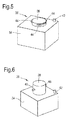
- FIG. 5 shows a third embodiment of the attachment arrangement 36 of the present invention applied to a block seal 34.
- the attachment arrangement 36 again comprises an elongate attachment feature 38 that is in the form of a solid cylinder extending away from a surface of the block seal 34.
- the attachment feature 38 is relatively short in this direction.
- there are a plurality of partial screw threads 44 three are drawn although other numbers are equally feasible.
- Each partial screw thread 44 extends round a part of the periphery of the attachment feature 38 so that in the first orientation one end of each partial screw thread 44 interdigitates with a matching feature on the component to which the seal is to be attached.
- the attachment feature 38 is then rotated by rotating the block seal 34, about a quarter turn, until it is in the second orientation, the partial screw threads 44 lock the attachment feature 38 to the component and the locking feature 42 engages an aperture in the component.
- partial screw threads 44 may be longer or shorter than shown in the third embodiment and consequently there may be fewer or more partial screw threads 44. Additionally the locking feature 42 may be located on the attachment feature 38 rather than on the block seal 34.
- Figure 6 shows a fourth embodiment of the attachment arrangement 38.
- the locking feature 42 is shown on the block seal 34 although it is to be understood that it may alternatively be located on the attachment feature 38.
- the attachment feature 38 comprises pins 46 extending radially from the rotational axis of the attachment feature 38 to form a bayonet-style arrangement. As illustrated, two pins 46 extend diametrically opposite to each other but it is to be understood that more than two pins 46 may be provided.
- the pins 46 are preferably equi-angularly spaced but could alternatively be spaced unevenly around the periphery of the attachment feature 38 so that the block seal 34 can only be attached to the component in one orientation.
- the pins 46 are aligned with elongate apertures in the component to be sealed and inserted therethrough.
- the block seal 34 and integral attachment feature 38 are then rotated so that the pins 46 extend over part of the component to lock the block seal 34 to the component.
- the locking feature 42 engages at the appropriate orientation.
- the attachment arrangement 36 can be provided on a linear seal 48. It is intended that such a linear seal 48 can be used to seal a straight interface between components or to be flexed into a curvilinear shape to seal a curved interface.
- a linear seal 48 can be seen in Figure 7 in which the cross section is ⁇ -shaped, having a circular portion with a flat portion forming a tangent to the circular portion.
- the attachment arrangements 36 are spaced along the flat portion.
- each attachment arrangement 36 is of the third embodiment type having a plurality of partial screw threads 44 extending around the periphery of the attachment feature 38.
- a plurality of locking features 42 is located on the linear seal 48, with one locking feature 42 for each attachment arrangement 36.
- Figure 8 is substantially similar to Figure 7 except that each locking feature 42 is located on a respective attachment feature 38 instead of on the linear seal 48.
- Figure 9 shows the third embodiment of the attachment arrangement 36 having partial screw threads 44 extending around the periphery of the attachment feature 38. It is located on a linear seal 48, only part of which is shown.
- Figure 9 also shows a third embodiment of the locking feature. Instead of having the form of a pin 42 located on either the seal 34, 48 or on the attachment feature 38, the third embodiment of the locking feature modifies the end 50 of the attachment feature 38 itself.
- the end 50 of the attachment feature 38 that is distal to the linear seal 48 has a distorted shape so that it resembles two semi-circular portions that are each angled relative to the plane of the flat portion of the linear seal 48 and to each other.
- the end 50 is configured relative to the threads 44 so that in the first orientation of the attachment arrangement 36, parts of the component to which the linear seal 48 is attached abut part of the end 50.
- the attachment arrangement 36 is then rotated towards the second orientation in which the parts of the component ride up the portions of the end 50 until they drop onto the lowest part. In the second orientation further rotation in the same direction tightens the locking and reverse rotation is prevented by the vertical wall delimiting the two semi-circular portions from one another.
- Each linear seal 48 preferably has a plurality of attachment arrangements 36 provided along its length. Any of the second, third and fourth embodiments of the attachment arrangement 36 is suitable for attachment of the linear seal 48 to a component. In some applications it may be preferable to have a mixture of the embodiments so that, for example, an attachment arrangement 36 comprising partial screw threads 44 is adjacent to an attachment arrangement 36 comprising bayonet-style pins 46.
- the linear seal 48 is formed of a material having sufficient flexibility, and the attachment arrangements 36 are spaced accordingly, so that a user can rotate one attachment arrangement 36 and the portion of the linear seal 48 on which it is located at a time.
- the user starts at one end of the linear seal 48 and rotates the first attachment arrangement 36 to its first orientation relative to the component, pushes the attachment feature 38 towards the component to cause interdigitation of the attachment feature 38 and part of the component, and then rotates the attachment arrangement 36 to its second orientation.
- the user then moves along the linear seal 48 to the next attachment arrangement 36 and repeats the procedure until all the attachment arrangements 36 are locked to the component.
- This arrangement is advantageous because it is quick for the user to attach the seal to the component, and there are no extra parts to increase weight or get lost or to work loose and cause damage.
- the user works along the seal rotating each attachment arrangement 36 in turn from its second orientation to its first orientation where it can be moved away from the component. This is quick and simple to do.
- the locking features 42, 50 reduce the likelihood that the attachment will work loose during use, for example under stress from vibrations, and further secure the seal 34, 48 to the component. There may be a locking feature 42, 50 for each attachment arrangement 36 or fewer locking features 42 than attachment arrangements 36.
- silicon sealant may be applied to the flat portion of the linear seal 48 before the attachment arrangements 36 are attached to the component so that additionally sealing is provided. This may be necessary where the linear seal 48 is made from a highly rigid material so that the attachment arrangements 36 are well spaced apart from each other. It should be appreciated that applying silicon sealant makes it slower to remove and replace the seal 34, 48.
- the linear seal 48 has been described as ⁇ -shaped in cross section, it may have a different shape in cross section. For example, it may be 'double ⁇ -shaped' in cross section, having a circular portion with opposed flat surfaces.
- the attachment arrangements 36 are provided on each of the flat surfaces.
- an attachment arrangement 36 on one flat surface is aligned with an attachment arrangement 36 on the other flat surface to form an opposed pair.
- the opposed pair of attachment arrangements 36 are arranged so that rotation of that part of the seal in one direction moves both attachment features 38 from their first orientation to their second orientation.
- the attachment features 38 comprise screw threads 40 or partial screw threads 44
- one of the opposed pair has a right-hand thread and the other of the opposed pair has a left-hand thread.
- the opposed pair of attachment arrangements 36 can therefore be attached to the respective components at the same time.
- the seal can be configured to have different material properties in the seal part and in the attachment arrangement 36.
- the block 34 or linear seal 48 may be more flexible than the attachment arrangement 36 so that the part of the seal near the attachment arrangement 36 may be rotated to move the attachment arrangement 36 between its first and second orientations, whilst the attachment arrangement 36 will not be flexible enough to distort out of its locking, second orientation.
- the block 34 may be manufactured by moulding, building up in layers. It is possible to vary the material properties during manufacture by varying the materials in successive layers so that the attachment arrangement 36 is integral to the seal 34, 48 and it is not necessary to form the seal part and attachment arrangement 36 separately and then bond them together.
- the layers may comprise PTFE or elastomer, fibre glass, ceramic fibres or solid ceramic and rubber with different levels of vulcanisation.
- the moulding process can incorporate a metal locking feature 42 if required.
- Figure 10 shows a seal locking plate 52 suitable for use with, for example, the linear seal 48 of Figure 7 .
- the seal locking plate 52 may form the surface of one of the components forming the interface to be sealed or may be a separate component affixed to that component.
- the seal locking plate 52 comprises a plurality of attachment apertures 54 that are configured and arranged to receive corresponding attachment arrangements 36 when the linear seal 48 is brought into engagement with the seal locking plate 52.
- the interior of each attachment aperture 54 may be threaded to engage with the partial screw threads 44 of the third embodiment of the attachment arrangement 36.
- the seal locking plate 52 also comprises a plurality of locking apertures 56 that are configured and arranged to receive respective locking features 42 when each attachment arrangement 36 is rotated to its second orientation after it is received in its respective attachment aperture 54 in its first orientation.
- the seal locking plate 52 may have a different configuration for different embodiments of the attachment arrangements 36 and the locking features 42.
- the locking apertures 56 comprise deeper recesses in a predetermined position in the attachment apertures 54.
- the inside of the attachment apertures 54 could be shaped to receive the ends 50 of attachment features 38 of the third embodiment of the locking feature, and no separate locking apertures 56 provided.
- Figure 11 shows an alternative configuration of the seal locking plate 52 in which the attachment apertures 54 are shaped to receive the bayonet-style pins 46 of the attachment features 38 of the fourth embodiment of the attachment arrangement 36.
- the attachment apertures 54 are circular with a pair of elongate recesses extending away from the main part of the aperture that are sized to receive the pins 46 therethrough when the attachments arrangements 36 are in their first orientation.
- the pins 46 are rotated until, in the second orientation, they extend over a part of the seal locking plate 52 defining the attachment apertures 54 that does not include the recesses.
- Figure 10 and Figure 11 show a locking aperture 56 for each attachment aperture 54
- the invention can also be put into effect with fewer locking apertures 56 and corresponding locking features 42 than attachment apertures 54 and attachment arrangements 36.
- more locking apertures 56 and locking features 42 may be provided than attachment apertures 54 and attachment arrangements 36.
- the seal with integral attachment arrangement is advantageous in a variety of applications, particularly those where it is necessary to periodically remove and replace the seals and where it is important that the sealing is as leak-proof as possible.
- the invention finds particular utility for aerodynamic seals in aerospace applications including the engines, auxiliary power units, aircraft doors and escape hatches. Similarly, it finds utility for tidal turbines and ships; sealing fire zones for nuclear plants and test cells; and for sealing fire sensitive areas of military vehicles such as tanks.
Landscapes
- Engineering & Computer Science (AREA)
- General Engineering & Computer Science (AREA)
- Mechanical Engineering (AREA)
- Gasket Seals (AREA)
Abstract
Description
- The present invention relates to a seal having an integral attachment arrangement.
- Seals are used in a variety of applications to prevent movement of fluid across an interface. It is usually necessary to attach the seal to one or both of the components forming the interface to fix it in place and at the desired orientation. In aerospace applications, among others, seals have a short life compared to other components and therefore need to be replaced regularly. It is therefore advantageous to attach the seal in a manner that allows quick and simple removal and replacement.
- It is known to chemically bond seals to components. However, in order to replace a chemically bonded seal it is necessary to remove it, often by cutting away, and then to clean the surface of the component before a new seal can be chemically bonded in place. This is time-consuming and thus expensive.
- It is also known to use mechanical attachment arrangements such as rivets, bolts, clips and the like. However, rivets must be drilled out in order to remove and replace a seal which is time-consuming and expensive. Bolts introduce a significantly higher parts count which may increase the weight, problematic in some applications particularly for aerospace, and raises the risk of foreign object damage to components from dropped or shed nuts, bolts or washers. Clips must be accurately sized in order to perform and are unsuitable where there is noticeable movement across the seal interface, for example caused by vibration. Clips are therefore relatively expensive to manufacture, may be ineffective and increase the risk of foreign object damage to components from dropped or shed clips.
- Where a seal is used to seal between fire zones, in a gas turbine engine, power plant, ship or other application, it is critical that the seal is securely attached to one or both components forming the interface to be sealed, that it remains attached in fire conditions and that it can be efficiently replaced as required.
- The present invention provides a seal that seeks to address the aforementioned problems.
- Accordingly the present invention provides a seal having an integral attachment arrangement, the attachment arrangement comprising at least one attachment feature and at least one locking feature, the at least one attachment feature configured and arranged to interdigitate with features of another component in a first orientation and to lock to the other component in a second orientation, wherein the second orientation is rotationally displaced from the first orientation. This is advantageous because it reduces the part count and weight by obviating the need for additional clips or other retaining features to hold the seal into position. It also improves the speed and reliability of fitting and the ease of replacement.
- The at least one attachment feature may comprise bayonet-type protrusions. This is quick and simple to fit. Alternatively, the at least one attachment feature may comprise a partial screw thread extending at least some of the way around the periphery of the attachment feature. This provides a more load-resistant fitting.
- The at least one locking feature may comprise a pin located on the seal or located on the attachment feature. Alternatively the at least one locking feature may comprise a distorted shape to the attachment feature at the end distal to the seal. Alternatively the locking feature may comprise an uneven pitch screw thread. All of these locking features resist accidental rotation of the seal to disengage the seal from the component to which it is coupled.
- The seal may be a block seal having one attachment feature and one locking feature. Alternatively the seal may be a linear seal having multiple attachment features. The seal is flexible such that each attachment feature is rotated between its first and second orientation by rotating that part of the seal on which it is located.
- The seal may be omega-shaped in cross section. Alternatively the seal may be double-omega shaped in cross section, being circular with opposed flat surfaces in cross section, the attachment features being arranged on the flat surfaces such that rotation in one direction moves opposed pairs of attachment features from their first to their second orientations. This increases the speed of fitting.
- The seal may be comprised of silicate impregnated elastomeric. The locking feature may also be comprised of silicate impregnated elastomeric or may be comprised of metal.
- The other component may comprise a seal locking plate having an attachment aperture to receive each of the at least one attachment features in the first orientation and to be locked to the at least one attachment feature in the second orientation.
- The present invention will be more fully described by way of example with reference to the accompanying drawings, in which:
-
Figure 1 is a sectional side view of a gas turbine engine in which a seal according to the present invention may be used. -
Figure 2 is a first embodiment of an attachment arrangement according to the present invention shown on a block seal with a first embodiment of a locking feature. -
Figure 3 is the first embodiment of the attachment arrangement according to the present invention shown on a block seal with a second embodiment of a locking feature. -
Figure 4 is a second embodiment of an attachment arrangement according to the present invention shown on a block seal with the first embodiment of the locking feature. -
Figure 5 is a third embodiment of an attachment arrangement according to the present invention shown on a block seal with the first embodiment of the locking feature. -
Figure 6 is a fourth embodiment of an attachment arrangement according to the present invention shown on a block seal with the first embodiment of the locking feature. -
Figure 7 is the third embodiment of the attachment arrangement according to the present invention shown on a linear seal with the first embodiment of the locking feature. -
Figure 8 is the third embodiment of the attachment arrangement according to the present invention shown on a linear seal with the second embodiment of the locking feature. -
Figure 9 is an enlargement of the third embodiment of the attachment arrangement according to the present invention shown on a linear seal with a third embodiment of a locking feature. -
Figure 10 is a first embodiment of a seal locking plate. -
Figure 11 is a second embodiment of a seal locking plate. - A
gas turbine engine 10 is shown inFigure 1 and comprises anair intake 12 and apropulsive fan 14 that generates two airflows A and B. Thegas turbine engine 10 comprises, in axial flow A, anintermediate pressure compressor 16, ahigh pressure compressor 18, acombustor 20, a high pressure turbine 22, an intermediate pressure turbine 24, alow pressure turbine 26 and anexhaust nozzle 28. Anacelle 30 surrounds thegas turbine engine 10 and defines, in axial flow B, abypass duct 32. - The
gas turbine engine 10 is separated into fire zones, there being interfaces between adjacent fire zones that require sealing. For certification of a gas turbine engine it is necessary to prevent fire from propagating through such boundaries for a given period of time and to arrest propagation for a further period thereafter to allow safe shut down of the engine or other remedial action to occur. It is therefore necessary that the seal does not become detached from the components forming the interface. - A
block seal 34 is generally positioned at the end of a linear orcurvilinear seal 48 in order to seal the end of thatlinear seal 48. Theblock seal 34 is substantially cubic and is hollow to allow some compression in sealing. Ablock seal 34 may be formed from a silicate impregnated elastomeric, where the silicate may be glass, which is highly rigid so that it retains it shape but has sufficient flexibility to be marginally compressible to improve its sealing capability. A pad seal is similar to ablock seal 34 but is typically compressed in one direction only, whereas ablock seal 34 is often subjected to compression forces in more than one direction at once. - A
block seal 34 comprising a first embodiment of anattachment arrangement 36 according to the present invention is shown inFigure 2 . This embodiment is suitable for attachment to one component forming an interface to be sealed, the other component abutting theblock seal 34 on the surface opposed to theattachment arrangement 36. Theattachment arrangement 36 comprises an elongate attachment feature 38 in the form of a solid upstanding cylinder. There is ascrew thread 40 that extends around the periphery of theattachment feature 38 for engagement with another component. The length of thescrew thread 40 is determined by the particular application and depends on the required interference load and strength of seal attachment to the component. In this embodiment thescrew thread 40 circumnavigates theattachment feature 38 several times. - The
screw thread 40 on theattachment feature 38 is configured and arranged to interdigitate with a matching groove feature of one of the components to be sealed (not shown) in a first orientation. Rotating theblock seal 34 and integral attachment feature 38 screws thescrew thread 40 into the component to be sealed until theattachment feature 38 is in a second orientation and locked to the component. In this embodiment, the first and second orientations may be aligned but rotational displacement is required to move from the first to the second orientation. Alternatively, the ends of thescrew thread 40 may be unaligned so that the first and second orientations are also unaligned. - The embodiment of
Figure 2 also comprises ananti-rotation locking feature 42 located on theblock seal 34. The lockingfeature 42 is a pin extending parallel to theattachment feature 38 and is arranged to engage with an aperture in the component to which theblock seal 34 is attached in order to prevent theblock seal 34 from being inadvertently detached. The lockingfeature 42 may comprise the same material as theblock seal 34, for example the silicate impregnated elastomeric, in which case the lockingfeature 42 may be integrally formed with or bonded to theblock seal 34. Alternatively the lockingfeature 42 may comprise metal and be bonded to or otherwise secured to theblock seal 34. -
Figure 3 shows the first embodiment of theattachment arrangement 36 but with the lockingfeature 42, comprising a pin, located on the end of theattachment feature 38 that is distal to theblock seal 34 rather than located on theblock seal 34 itself. -
Figure 4 shows a second embodiment of theattachment arrangement 36 for ablock seal 34 with the lockingfeature 42 located on theblock seal 34 as in the first embodiment (Figure 2 ). In this embodiment theattachment feature 38 is shorter than in the first embodiment and thescrew thread 40 is only long enough that the second orientation of theattachment arrangement 36 is rotationally displaced by half a revolution from the first orientation. This means that attachment of theblock seal 34 to the component is quicker than the first embodiment, although it may be less resistant to loading. For example, ablock seal 34 located at the end of a C-duct is subjected to simultaneous shear and compression loading, the shear being applied on a radius as the duct pivots closed. -
Figure 5 shows a third embodiment of theattachment arrangement 36 of the present invention applied to ablock seal 34. Theattachment arrangement 36 again comprises anelongate attachment feature 38 that is in the form of a solid cylinder extending away from a surface of theblock seal 34. Theattachment feature 38 is relatively short in this direction. In this embodiment there are a plurality ofpartial screw threads 44, three are drawn although other numbers are equally feasible. Eachpartial screw thread 44 extends round a part of the periphery of theattachment feature 38 so that in the first orientation one end of eachpartial screw thread 44 interdigitates with a matching feature on the component to which the seal is to be attached. Theattachment feature 38 is then rotated by rotating theblock seal 34, about a quarter turn, until it is in the second orientation, thepartial screw threads 44 lock theattachment feature 38 to the component and the lockingfeature 42 engages an aperture in the component. - Although not illustrated, the
partial screw threads 44 may be longer or shorter than shown in the third embodiment and consequently there may be fewer or morepartial screw threads 44. Additionally the lockingfeature 42 may be located on theattachment feature 38 rather than on theblock seal 34. -
Figure 6 shows a fourth embodiment of theattachment arrangement 38. The lockingfeature 42 is shown on theblock seal 34 although it is to be understood that it may alternatively be located on theattachment feature 38. In this embodiment theattachment feature 38 comprisespins 46 extending radially from the rotational axis of theattachment feature 38 to form a bayonet-style arrangement. As illustrated, twopins 46 extend diametrically opposite to each other but it is to be understood that more than twopins 46 may be provided. Thepins 46 are preferably equi-angularly spaced but could alternatively be spaced unevenly around the periphery of theattachment feature 38 so that theblock seal 34 can only be attached to the component in one orientation. - In the first orientation of the fourth embodiment, the
pins 46 are aligned with elongate apertures in the component to be sealed and inserted therethrough. Theblock seal 34 andintegral attachment feature 38 are then rotated so that thepins 46 extend over part of the component to lock theblock seal 34 to the component. The lockingfeature 42 engages at the appropriate orientation. - Instead of a
block seal 34, theattachment arrangement 36 can be provided on alinear seal 48. It is intended that such alinear seal 48 can be used to seal a straight interface between components or to be flexed into a curvilinear shape to seal a curved interface. One form of thelinear seal 48 can be seen inFigure 7 in which the cross section is Ω-shaped, having a circular portion with a flat portion forming a tangent to the circular portion. Preferably there aremultiple attachment arrangements 36 provided for attaching thelinear seal 48 to a component. Theattachment arrangements 36 are spaced along the flat portion. InFigure 7 eachattachment arrangement 36 is of the third embodiment type having a plurality ofpartial screw threads 44 extending around the periphery of theattachment feature 38. A plurality of locking features 42 is located on thelinear seal 48, with onelocking feature 42 for eachattachment arrangement 36. -
Figure 8 is substantially similar toFigure 7 except that each lockingfeature 42 is located on a respective attachment feature 38 instead of on thelinear seal 48. -
Figure 9 shows the third embodiment of theattachment arrangement 36 havingpartial screw threads 44 extending around the periphery of theattachment feature 38. It is located on alinear seal 48, only part of which is shown.Figure 9 also shows a third embodiment of the locking feature. Instead of having the form of apin 42 located on either theseal attachment feature 38, the third embodiment of the locking feature modifies theend 50 of theattachment feature 38 itself. Theend 50 of theattachment feature 38 that is distal to thelinear seal 48 has a distorted shape so that it resembles two semi-circular portions that are each angled relative to the plane of the flat portion of thelinear seal 48 and to each other. Theend 50 is configured relative to thethreads 44 so that in the first orientation of theattachment arrangement 36, parts of the component to which thelinear seal 48 is attached abut part of theend 50. Theattachment arrangement 36 is then rotated towards the second orientation in which the parts of the component ride up the portions of theend 50 until they drop onto the lowest part. In the second orientation further rotation in the same direction tightens the locking and reverse rotation is prevented by the vertical wall delimiting the two semi-circular portions from one another. - Although the
linear seal 48 arrangements have each been shown with the same, third embodiment of theattachment arrangement 36 it will be apparent to the skilled reader that any of the embodiments may be used. In particular the bayonet-style pins 46 may be provided on theattachment feature 38 instead of thepartial screw threads 44. - Each
linear seal 48 preferably has a plurality ofattachment arrangements 36 provided along its length. Any of the second, third and fourth embodiments of theattachment arrangement 36 is suitable for attachment of thelinear seal 48 to a component. In some applications it may be preferable to have a mixture of the embodiments so that, for example, anattachment arrangement 36 comprisingpartial screw threads 44 is adjacent to anattachment arrangement 36 comprising bayonet-style pins 46. Thelinear seal 48 is formed of a material having sufficient flexibility, and theattachment arrangements 36 are spaced accordingly, so that a user can rotate oneattachment arrangement 36 and the portion of thelinear seal 48 on which it is located at a time. - Thus the user starts at one end of the
linear seal 48 and rotates thefirst attachment arrangement 36 to its first orientation relative to the component, pushes theattachment feature 38 towards the component to cause interdigitation of theattachment feature 38 and part of the component, and then rotates theattachment arrangement 36 to its second orientation. The user then moves along thelinear seal 48 to thenext attachment arrangement 36 and repeats the procedure until all theattachment arrangements 36 are locked to the component. This arrangement is advantageous because it is quick for the user to attach the seal to the component, and there are no extra parts to increase weight or get lost or to work loose and cause damage. To remove and replace thelinear seal 48, the user works along the seal rotating eachattachment arrangement 36 in turn from its second orientation to its first orientation where it can be moved away from the component. This is quick and simple to do. - The locking features 42, 50 reduce the likelihood that the attachment will work loose during use, for example under stress from vibrations, and further secure the
seal feature attachment arrangement 36 or fewer locking features 42 thanattachment arrangements 36. - Optionally silicon sealant may be applied to the flat portion of the
linear seal 48 before theattachment arrangements 36 are attached to the component so that additionally sealing is provided. This may be necessary where thelinear seal 48 is made from a highly rigid material so that theattachment arrangements 36 are well spaced apart from each other. It should be appreciated that applying silicon sealant makes it slower to remove and replace theseal - Although the
linear seal 48 has been described as Ω-shaped in cross section, it may have a different shape in cross section. For example, it may be 'double Ω-shaped' in cross section, having a circular portion with opposed flat surfaces. In this case, theattachment arrangements 36 are provided on each of the flat surfaces. In a preferred embodiment, anattachment arrangement 36 on one flat surface is aligned with anattachment arrangement 36 on the other flat surface to form an opposed pair. The opposed pair ofattachment arrangements 36 are arranged so that rotation of that part of the seal in one direction moves both attachment features 38 from their first orientation to their second orientation. In the embodiments where the attachment features 38 comprisescrew threads 40 orpartial screw threads 44, one of the opposed pair has a right-hand thread and the other of the opposed pair has a left-hand thread. The opposed pair ofattachment arrangements 36 can therefore be attached to the respective components at the same time. - Whether the
block seal 34 orlinear seal 48 is used, the seal can be configured to have different material properties in the seal part and in theattachment arrangement 36. Thus theblock 34 orlinear seal 48 may be more flexible than theattachment arrangement 36 so that the part of the seal near theattachment arrangement 36 may be rotated to move theattachment arrangement 36 between its first and second orientations, whilst theattachment arrangement 36 will not be flexible enough to distort out of its locking, second orientation. Theblock 34 may be manufactured by moulding, building up in layers. It is possible to vary the material properties during manufacture by varying the materials in successive layers so that theattachment arrangement 36 is integral to theseal attachment arrangement 36 separately and then bond them together. For example, the layers may comprise PTFE or elastomer, fibre glass, ceramic fibres or solid ceramic and rubber with different levels of vulcanisation. The moulding process can incorporate ametal locking feature 42 if required. -
Figure 10 shows aseal locking plate 52 suitable for use with, for example, thelinear seal 48 ofFigure 7 . Theseal locking plate 52 may form the surface of one of the components forming the interface to be sealed or may be a separate component affixed to that component. Theseal locking plate 52 comprises a plurality ofattachment apertures 54 that are configured and arranged to receivecorresponding attachment arrangements 36 when thelinear seal 48 is brought into engagement with theseal locking plate 52. The interior of eachattachment aperture 54 may be threaded to engage with thepartial screw threads 44 of the third embodiment of theattachment arrangement 36. Theseal locking plate 52 also comprises a plurality of lockingapertures 56 that are configured and arranged to receive respective locking features 42 when eachattachment arrangement 36 is rotated to its second orientation after it is received in itsrespective attachment aperture 54 in its first orientation. - It is to be understood that the
seal locking plate 52 may have a different configuration for different embodiments of theattachment arrangements 36 and the locking features 42. For example, to be suitable for use with thelinear seal 48 ofFigure 8 the lockingapertures 56 comprise deeper recesses in a predetermined position in theattachment apertures 54. Alternatively, the inside of theattachment apertures 54 could be shaped to receive theends 50 of attachment features 38 of the third embodiment of the locking feature, and noseparate locking apertures 56 provided. -
Figure 11 shows an alternative configuration of theseal locking plate 52 in which theattachment apertures 54 are shaped to receive the bayonet-style pins 46 of the attachment features 38 of the fourth embodiment of theattachment arrangement 36. Thus theattachment apertures 54 are circular with a pair of elongate recesses extending away from the main part of the aperture that are sized to receive thepins 46 therethrough when theattachments arrangements 36 are in their first orientation. Thepins 46 are rotated until, in the second orientation, they extend over a part of theseal locking plate 52 defining theattachment apertures 54 that does not include the recesses. - Although
Figure 10 andFigure 11 show a lockingaperture 56 for eachattachment aperture 54, the invention can also be put into effect withfewer locking apertures 56 and corresponding locking features 42 thanattachment apertures 54 andattachment arrangements 36. Alternatively more lockingapertures 56 and locking features 42 may be provided thanattachment apertures 54 andattachment arrangements 36. - The seal with integral attachment arrangement is advantageous in a variety of applications, particularly those where it is necessary to periodically remove and replace the seals and where it is important that the sealing is as leak-proof as possible. The invention finds particular utility for aerodynamic seals in aerospace applications including the engines, auxiliary power units, aircraft doors and escape hatches. Similarly, it finds utility for tidal turbines and ships; sealing fire zones for nuclear plants and test cells; and for sealing fire sensitive areas of military vehicles such as tanks.
Claims (15)
- A seal (34, 48) having an integral attachment arrangement (36), the attachment arrangement (36) comprising at least one attachment feature (38) and at least one locking feature (42), the at least one attachment feature (38) configured and arranged to interdigitate with features of another component in a first orientation and to lock to the other component in a second orientation, wherein the second orientation is rotationally displaced from the first orientation.
- A seal (34, 48) as claimed in claim 1 wherein the at least one attachment feature (38) comprises bayonet-type protrusions (46).
- A seal (34, 48) as claimed in claim 1 wherein the at least one attachment feature (38) comprises a partial screw thread (40, 44) extending at least some of the way around the periphery of the attachment feature (38).
- A seal (34, 48) as claimed in any preceding claim wherein the at least one locking feature (42) comprises a pin located on the seal (34, 48).
- A seal (34, 48) as claimed in any preceding claim wherein the at least one locking feature (42) comprises a pin located on the attachment feature (38).
- A seal (34, 48) as claimed in any preceding claim wherein the at least one locking feature (42) comprises a distorted shape to the attachment feature (38) at the end (50) distal to the seal (34, 48).
- A seal (34, 48) as claimed in any preceding claim wherein the at least one locking feature (42) comprises an uneven pitch screw thread.
- A seal (34, 48) as claimed in any preceding claim wherein the seal (34, 48) is a block seal (34, 48) having one attachment feature (38) and one locking feature (42).
- A seal (34, 48) as claimed in any of claims 1 to 7 wherein the seal (34, 48) is a linear seal (34, 48) having multiple attachment features (38).
- A seal (34, 48) as claimed in claim 9 wherein the seal (34, 48) is flexible such that each attachment feature (38) is rotated between its first and second orientation by rotating that part of the seal (34, 48) on which it is located.
- A seal (34, 48) as claimed in claim 9 or 10 wherein the seal (34, 48) is Ω-shaped in cross section.
- A seal (34, 48) as claimed in claim 9 or 10 wherein seal (34, 48) is circular with opposed flat surfaces in cross section, the attachment features (38) being arranged on the flat surfaces such that rotation in one direction moves opposed pairs of attachment features (38) from their first to their second orientations.
- A seal (34, 48) as claimed in any preceding claim wherein the seal (34, 48) is comprised of silicate impregnated elastomeric.
- A seal (34, 48) as claimed in any preceding claim wherein the locking feature (42) is comprised of silicate impregnated elastomeric or metal.
- A seal (34, 48) as claimed in any preceding claim wherein the other component comprises a seal locking plate (52) having an attachment aperture (54) to receive each of the at least one attachment features (38) in the first orientation and to be locked to the at least one attachment feature (38) in the second orientation.
Applications Claiming Priority (1)
| Application Number | Priority Date | Filing Date | Title |
|---|---|---|---|
| GB201010169A GB201010169D0 (en) | 2010-06-17 | 2010-06-17 | A seal |
Publications (2)
| Publication Number | Publication Date |
|---|---|
| EP2397725A1 true EP2397725A1 (en) | 2011-12-21 |
| EP2397725B1 EP2397725B1 (en) | 2016-07-06 |
Family
ID=42471795
Family Applications (1)
| Application Number | Title | Priority Date | Filing Date |
|---|---|---|---|
| EP11166324.1A Not-in-force EP2397725B1 (en) | 2010-06-17 | 2011-05-17 | A seal |
Country Status (3)
| Country | Link |
|---|---|
| US (1) | US8882422B2 (en) |
| EP (1) | EP2397725B1 (en) |
| GB (1) | GB201010169D0 (en) |
Cited By (1)
| Publication number | Priority date | Publication date | Assignee | Title |
|---|---|---|---|---|
| CN113357367A (en) * | 2021-05-27 | 2021-09-07 | 中国航发南方工业有限公司 | Sealing device and sealing method for oil way inlet on slewing box |
Citations (6)
| Publication number | Priority date | Publication date | Assignee | Title |
|---|---|---|---|---|
| US4004626A (en) * | 1975-06-06 | 1977-01-25 | Amerace Corporation | Self-sealing, self-locking threaded fastener |
| DE3115036A1 (en) * | 1981-04-14 | 1982-11-04 | Denso-Chemie Wedekind Kg, 5090 Leverkusen | Sealing arrangements, in particular for a spigot and socket joint on pipes |
| US5107623A (en) * | 1987-10-16 | 1992-04-28 | Davlyn Manufacturing Co., Inc. | Gaskets and gasket-like devices with fasteners |
| WO2007122134A1 (en) * | 2006-04-21 | 2007-11-01 | Nmc S.A. | Sealing system |
| WO2010012347A1 (en) * | 2008-07-30 | 2010-02-04 | Sew-Eurodrive Gmbh & Co. Kg | Arrangement for sealing a recess in a base body |
| US20100078932A1 (en) * | 2008-09-26 | 2010-04-01 | Gurtatowski Craig W | Grommet and fuel fill housing assembly including the same |
Family Cites Families (20)
| Publication number | Priority date | Publication date | Assignee | Title |
|---|---|---|---|---|
| US1184173A (en) * | 1916-02-12 | 1916-05-23 | Adam J Gehring | Wood-screw. |
| US1829293A (en) * | 1929-05-17 | 1931-10-27 | Shakeproof Lock Washer Co | Screw lock |
| US2638642A (en) * | 1948-10-06 | 1953-05-19 | Bridgeport Fabrics Inc | Sealing strip |
| US2586869A (en) * | 1950-08-30 | 1952-02-26 | Us Army | Waterproof pilot lamp |
| DE1750702A1 (en) * | 1968-05-27 | 1971-02-18 | Boellhoff & Co | Screw piece, in particular nut, with a sealing and locking ring made of thermoplastic material |
| US3661046A (en) * | 1970-11-09 | 1972-05-09 | Illinois Tool Works | Combination screw |
| DE3503012A1 (en) * | 1985-01-30 | 1986-07-31 | Dyckerhoff & Widmann AG, 8000 München | TENSIONING DEVICE FOR THE TIE LINK OF AN ANCHOR, ESPECIALLY A ROCK ANCHOR |
| US4861197A (en) * | 1987-06-15 | 1989-08-29 | Jennmar Corporation | Roof bolt system |
| US4842364A (en) * | 1988-10-11 | 1989-06-27 | Jack Moon Co. Ltd., Taiwan | Fiber optic cable innerduct plug and assembly |
| US5074773A (en) * | 1990-04-12 | 1991-12-24 | Davidson Textron Inc. | Adjustable gasket alignment block |
| DE4310510C2 (en) * | 1993-03-31 | 1995-04-20 | Freudenberg Carl Fa | Bellows |
| FR2762455B1 (en) * | 1997-04-16 | 1999-06-25 | Sofanou Sa | WATERPROOF CONNECTING PIECE OF A WALL TUBE |
| US6386545B1 (en) * | 1999-05-17 | 2002-05-14 | Robert W. Evans | Fluid plug |
| US6533288B1 (en) * | 2000-06-16 | 2003-03-18 | Walbro Corporation | Flange seal assembly |
| US7798755B2 (en) * | 2005-04-20 | 2010-09-21 | Erwin Tomm | Threaded connector with interlock |
| US20070040335A1 (en) | 2005-08-22 | 2007-02-22 | General Electric Company | Axially adjustable sealing ring |
| JP2007162812A (en) | 2005-12-13 | 2007-06-28 | Kenwood Corp | Mounting structure of operating component |
| US7862280B2 (en) * | 2006-08-26 | 2011-01-04 | Taiwan Shan Yin International Co., Ltd. | Saw tooth screw |
| US7751676B2 (en) * | 2006-11-22 | 2010-07-06 | Alcatel Lucent | Cable entry seal |
| CN101918056A (en) * | 2007-10-17 | 2010-12-15 | 大洋药品工业株式会社 | Sealing ring and its application |
-
2010
- 2010-06-17 GB GB201010169A patent/GB201010169D0/en not_active Ceased
-
2011
- 2011-05-17 EP EP11166324.1A patent/EP2397725B1/en not_active Not-in-force
- 2011-05-17 US US13/109,468 patent/US8882422B2/en active Active
Patent Citations (6)
| Publication number | Priority date | Publication date | Assignee | Title |
|---|---|---|---|---|
| US4004626A (en) * | 1975-06-06 | 1977-01-25 | Amerace Corporation | Self-sealing, self-locking threaded fastener |
| DE3115036A1 (en) * | 1981-04-14 | 1982-11-04 | Denso-Chemie Wedekind Kg, 5090 Leverkusen | Sealing arrangements, in particular for a spigot and socket joint on pipes |
| US5107623A (en) * | 1987-10-16 | 1992-04-28 | Davlyn Manufacturing Co., Inc. | Gaskets and gasket-like devices with fasteners |
| WO2007122134A1 (en) * | 2006-04-21 | 2007-11-01 | Nmc S.A. | Sealing system |
| WO2010012347A1 (en) * | 2008-07-30 | 2010-02-04 | Sew-Eurodrive Gmbh & Co. Kg | Arrangement for sealing a recess in a base body |
| US20100078932A1 (en) * | 2008-09-26 | 2010-04-01 | Gurtatowski Craig W | Grommet and fuel fill housing assembly including the same |
Cited By (2)
| Publication number | Priority date | Publication date | Assignee | Title |
|---|---|---|---|---|
| CN113357367A (en) * | 2021-05-27 | 2021-09-07 | 中国航发南方工业有限公司 | Sealing device and sealing method for oil way inlet on slewing box |
| CN113357367B (en) * | 2021-05-27 | 2023-11-03 | 中国航发南方工业有限公司 | Sealing device and sealing method for oil way inlet on rotary casing |
Also Published As
| Publication number | Publication date |
|---|---|
| US8882422B2 (en) | 2014-11-11 |
| US20110309587A1 (en) | 2011-12-22 |
| EP2397725B1 (en) | 2016-07-06 |
| GB201010169D0 (en) | 2010-07-21 |
Similar Documents
| Publication | Publication Date | Title |
|---|---|---|
| US9739162B2 (en) | Annulus filler | |
| US9752449B2 (en) | Annulus filler | |
| EP2341216B1 (en) | Turbine blade comprising an impact zone reinforcement | |
| RU2472945C2 (en) | Shim for turbine blade, turbine rotor structure and turbine | |
| DE102011057132B4 (en) | Assembly device for a turbine shroud with low ductility | |
| RU2465464C2 (en) | Turbine rotor design | |
| RU2472982C2 (en) | Improved nut and bolt | |
| CN101333943B (en) | Turbomachine stator damper device | |
| EP2500519B1 (en) | Turbine blade | |
| EP2108786A2 (en) | Aeroengine fan assembly | |
| US7766625B2 (en) | Methods and apparatus for reducing stress in turbine buckets | |
| EP2474712A2 (en) | Attachment of threaded holes to composite fan case | |
| CN109973415B (en) | Fragile airfoil for gas turbine engine | |
| US12134460B2 (en) | Blade comprising a composite material structure and associated manufacturing method | |
| CN111140539B (en) | Fragile gas turbine engine airfoils | |
| GB2448886A (en) | A turbomachine blade able to absorb impact energy from a foreign object | |
| CN101333939B (en) | Turbomachine shaft damper device | |
| EP2657449A2 (en) | Resistive band for turbomachine blade | |
| US20140356134A1 (en) | Dampers for fan spinners of aircraft engines | |
| US12025030B2 (en) | Blade comprising a structure made of composite material and associated manufacturing method | |
| CN102650236A (en) | Sealing device and method for providing a seal in a turbine system | |
| US9739163B2 (en) | Strip for abradable in a compressor turbine | |
| WO2010084320A2 (en) | Composite blade | |
| EP3081750A1 (en) | Damper ring for a rotor stage | |
| US8882422B2 (en) | Seal |
Legal Events
| Date | Code | Title | Description |
|---|---|---|---|
| AK | Designated contracting states |
Kind code of ref document: A1 Designated state(s): AL AT BE BG CH CY CZ DE DK EE ES FI FR GB GR HR HU IE IS IT LI LT LU LV MC MK MT NL NO PL PT RO RS SE SI SK SM TR |
|
| AX | Request for extension of the european patent |
Extension state: BA ME |
|
| PUAI | Public reference made under article 153(3) epc to a published international application that has entered the european phase |
Free format text: ORIGINAL CODE: 0009012 |
|
| 17P | Request for examination filed |
Effective date: 20120229 |
|
| 17Q | First examination report despatched |
Effective date: 20150226 |
|
| RAP1 | Party data changed (applicant data changed or rights of an application transferred) |
Owner name: ROLLS-ROYCE PLC |
|
| GRAP | Despatch of communication of intention to grant a patent |
Free format text: ORIGINAL CODE: EPIDOSNIGR1 |
|
| GRAS | Grant fee paid |
Free format text: ORIGINAL CODE: EPIDOSNIGR3 |
|
| INTG | Intention to grant announced |
Effective date: 20160329 |
|
| GRAA | (expected) grant |
Free format text: ORIGINAL CODE: 0009210 |
|
| AK | Designated contracting states |
Kind code of ref document: B1 Designated state(s): AL AT BE BG CH CY CZ DE DK EE ES FI FR GB GR HR HU IE IS IT LI LT LU LV MC MK MT NL NO PL PT RO RS SE SI SK SM TR |
|
| REG | Reference to a national code |
Ref country code: GB Ref legal event code: FG4D |
|
| REG | Reference to a national code |
Ref country code: AT Ref legal event code: REF Ref document number: 810965 Country of ref document: AT Kind code of ref document: T Effective date: 20160715 Ref country code: CH Ref legal event code: EP |
|
| REG | Reference to a national code |
Ref country code: IE Ref legal event code: FG4D |
|
| REG | Reference to a national code |
Ref country code: DE Ref legal event code: R096 Ref document number: 602011027878 Country of ref document: DE |
|
| REG | Reference to a national code |
Ref country code: NL Ref legal event code: MP Effective date: 20160706 |
|
| REG | Reference to a national code |
Ref country code: LT Ref legal event code: MG4D |
|
| REG | Reference to a national code |
Ref country code: AT Ref legal event code: MK05 Ref document number: 810965 Country of ref document: AT Kind code of ref document: T Effective date: 20160706 |
|
| PG25 | Lapsed in a contracting state [announced via postgrant information from national office to epo] |
Ref country code: IT Free format text: LAPSE BECAUSE OF FAILURE TO SUBMIT A TRANSLATION OF THE DESCRIPTION OR TO PAY THE FEE WITHIN THE PRESCRIBED TIME-LIMIT Effective date: 20160706 Ref country code: FI Free format text: LAPSE BECAUSE OF FAILURE TO SUBMIT A TRANSLATION OF THE DESCRIPTION OR TO PAY THE FEE WITHIN THE PRESCRIBED TIME-LIMIT Effective date: 20160706 Ref country code: RS Free format text: LAPSE BECAUSE OF FAILURE TO SUBMIT A TRANSLATION OF THE DESCRIPTION OR TO PAY THE FEE WITHIN THE PRESCRIBED TIME-LIMIT Effective date: 20160706 Ref country code: NL Free format text: LAPSE BECAUSE OF FAILURE TO SUBMIT A TRANSLATION OF THE DESCRIPTION OR TO PAY THE FEE WITHIN THE PRESCRIBED TIME-LIMIT Effective date: 20160706 Ref country code: LT Free format text: LAPSE BECAUSE OF FAILURE TO SUBMIT A TRANSLATION OF THE DESCRIPTION OR TO PAY THE FEE WITHIN THE PRESCRIBED TIME-LIMIT Effective date: 20160706 Ref country code: IS Free format text: LAPSE BECAUSE OF FAILURE TO SUBMIT A TRANSLATION OF THE DESCRIPTION OR TO PAY THE FEE WITHIN THE PRESCRIBED TIME-LIMIT Effective date: 20161106 Ref country code: HR Free format text: LAPSE BECAUSE OF FAILURE TO SUBMIT A TRANSLATION OF THE DESCRIPTION OR TO PAY THE FEE WITHIN THE PRESCRIBED TIME-LIMIT Effective date: 20160706 Ref country code: NO Free format text: LAPSE BECAUSE OF FAILURE TO SUBMIT A TRANSLATION OF THE DESCRIPTION OR TO PAY THE FEE WITHIN THE PRESCRIBED TIME-LIMIT Effective date: 20161006 |
|
| PG25 | Lapsed in a contracting state [announced via postgrant information from national office to epo] |
Ref country code: PL Free format text: LAPSE BECAUSE OF FAILURE TO SUBMIT A TRANSLATION OF THE DESCRIPTION OR TO PAY THE FEE WITHIN THE PRESCRIBED TIME-LIMIT Effective date: 20160706 Ref country code: LV Free format text: LAPSE BECAUSE OF FAILURE TO SUBMIT A TRANSLATION OF THE DESCRIPTION OR TO PAY THE FEE WITHIN THE PRESCRIBED TIME-LIMIT Effective date: 20160706 Ref country code: ES Free format text: LAPSE BECAUSE OF FAILURE TO SUBMIT A TRANSLATION OF THE DESCRIPTION OR TO PAY THE FEE WITHIN THE PRESCRIBED TIME-LIMIT Effective date: 20160706 Ref country code: GR Free format text: LAPSE BECAUSE OF FAILURE TO SUBMIT A TRANSLATION OF THE DESCRIPTION OR TO PAY THE FEE WITHIN THE PRESCRIBED TIME-LIMIT Effective date: 20161007 Ref country code: BE Free format text: LAPSE BECAUSE OF FAILURE TO SUBMIT A TRANSLATION OF THE DESCRIPTION OR TO PAY THE FEE WITHIN THE PRESCRIBED TIME-LIMIT Effective date: 20160706 Ref country code: AT Free format text: LAPSE BECAUSE OF FAILURE TO SUBMIT A TRANSLATION OF THE DESCRIPTION OR TO PAY THE FEE WITHIN THE PRESCRIBED TIME-LIMIT Effective date: 20160706 Ref country code: SE Free format text: LAPSE BECAUSE OF FAILURE TO SUBMIT A TRANSLATION OF THE DESCRIPTION OR TO PAY THE FEE WITHIN THE PRESCRIBED TIME-LIMIT Effective date: 20160706 Ref country code: PT Free format text: LAPSE BECAUSE OF FAILURE TO SUBMIT A TRANSLATION OF THE DESCRIPTION OR TO PAY THE FEE WITHIN THE PRESCRIBED TIME-LIMIT Effective date: 20161107 |
|
| REG | Reference to a national code |
Ref country code: DE Ref legal event code: R097 Ref document number: 602011027878 Country of ref document: DE |
|
| PG25 | Lapsed in a contracting state [announced via postgrant information from national office to epo] |
Ref country code: RO Free format text: LAPSE BECAUSE OF FAILURE TO SUBMIT A TRANSLATION OF THE DESCRIPTION OR TO PAY THE FEE WITHIN THE PRESCRIBED TIME-LIMIT Effective date: 20160706 Ref country code: EE Free format text: LAPSE BECAUSE OF FAILURE TO SUBMIT A TRANSLATION OF THE DESCRIPTION OR TO PAY THE FEE WITHIN THE PRESCRIBED TIME-LIMIT Effective date: 20160706 |
|
| PLBE | No opposition filed within time limit |
Free format text: ORIGINAL CODE: 0009261 |
|
| STAA | Information on the status of an ep patent application or granted ep patent |
Free format text: STATUS: NO OPPOSITION FILED WITHIN TIME LIMIT |
|
| REG | Reference to a national code |
Ref country code: FR Ref legal event code: PLFP Year of fee payment: 7 |
|
| PG25 | Lapsed in a contracting state [announced via postgrant information from national office to epo] |
Ref country code: BG Free format text: LAPSE BECAUSE OF FAILURE TO SUBMIT A TRANSLATION OF THE DESCRIPTION OR TO PAY THE FEE WITHIN THE PRESCRIBED TIME-LIMIT Effective date: 20161006 Ref country code: CZ Free format text: LAPSE BECAUSE OF FAILURE TO SUBMIT A TRANSLATION OF THE DESCRIPTION OR TO PAY THE FEE WITHIN THE PRESCRIBED TIME-LIMIT Effective date: 20160706 Ref country code: SK Free format text: LAPSE BECAUSE OF FAILURE TO SUBMIT A TRANSLATION OF THE DESCRIPTION OR TO PAY THE FEE WITHIN THE PRESCRIBED TIME-LIMIT Effective date: 20160706 Ref country code: DK Free format text: LAPSE BECAUSE OF FAILURE TO SUBMIT A TRANSLATION OF THE DESCRIPTION OR TO PAY THE FEE WITHIN THE PRESCRIBED TIME-LIMIT Effective date: 20160706 Ref country code: SM Free format text: LAPSE BECAUSE OF FAILURE TO SUBMIT A TRANSLATION OF THE DESCRIPTION OR TO PAY THE FEE WITHIN THE PRESCRIBED TIME-LIMIT Effective date: 20160706 |
|
| 26N | No opposition filed |
Effective date: 20170407 |
|
| PG25 | Lapsed in a contracting state [announced via postgrant information from national office to epo] |
Ref country code: LU Free format text: LAPSE BECAUSE OF NON-PAYMENT OF DUE FEES Effective date: 20170531 Ref country code: SI Free format text: LAPSE BECAUSE OF FAILURE TO SUBMIT A TRANSLATION OF THE DESCRIPTION OR TO PAY THE FEE WITHIN THE PRESCRIBED TIME-LIMIT Effective date: 20160706 |
|
| REG | Reference to a national code |
Ref country code: CH Ref legal event code: PL |
|
| PG25 | Lapsed in a contracting state [announced via postgrant information from national office to epo] |
Ref country code: MC Free format text: LAPSE BECAUSE OF FAILURE TO SUBMIT A TRANSLATION OF THE DESCRIPTION OR TO PAY THE FEE WITHIN THE PRESCRIBED TIME-LIMIT Effective date: 20160706 |
|
| REG | Reference to a national code |
Ref country code: IE Ref legal event code: MM4A |
|
| PG25 | Lapsed in a contracting state [announced via postgrant information from national office to epo] |
Ref country code: CH Free format text: LAPSE BECAUSE OF NON-PAYMENT OF DUE FEES Effective date: 20170531 Ref country code: LI Free format text: LAPSE BECAUSE OF NON-PAYMENT OF DUE FEES Effective date: 20170531 |
|
| PG25 | Lapsed in a contracting state [announced via postgrant information from national office to epo] |
Ref country code: LU Free format text: LAPSE BECAUSE OF NON-PAYMENT OF DUE FEES Effective date: 20170517 |
|
| PG25 | Lapsed in a contracting state [announced via postgrant information from national office to epo] |
Ref country code: IE Free format text: LAPSE BECAUSE OF NON-PAYMENT OF DUE FEES Effective date: 20170517 |
|
| REG | Reference to a national code |
Ref country code: FR Ref legal event code: PLFP Year of fee payment: 8 |
|
| PGFP | Annual fee paid to national office [announced via postgrant information from national office to epo] |
Ref country code: DE Payment date: 20180529 Year of fee payment: 8 |
|
| PGFP | Annual fee paid to national office [announced via postgrant information from national office to epo] |
Ref country code: FR Payment date: 20180525 Year of fee payment: 8 |
|
| PG25 | Lapsed in a contracting state [announced via postgrant information from national office to epo] |
Ref country code: MT Free format text: LAPSE BECAUSE OF NON-PAYMENT OF DUE FEES Effective date: 20170517 |
|
| PG25 | Lapsed in a contracting state [announced via postgrant information from national office to epo] |
Ref country code: AL Free format text: LAPSE BECAUSE OF FAILURE TO SUBMIT A TRANSLATION OF THE DESCRIPTION OR TO PAY THE FEE WITHIN THE PRESCRIBED TIME-LIMIT Effective date: 20160706 |
|
| PG25 | Lapsed in a contracting state [announced via postgrant information from national office to epo] |
Ref country code: HU Free format text: LAPSE BECAUSE OF FAILURE TO SUBMIT A TRANSLATION OF THE DESCRIPTION OR TO PAY THE FEE WITHIN THE PRESCRIBED TIME-LIMIT; INVALID AB INITIO Effective date: 20110517 |
|
| PG25 | Lapsed in a contracting state [announced via postgrant information from national office to epo] |
Ref country code: CY Free format text: LAPSE BECAUSE OF NON-PAYMENT OF DUE FEES Effective date: 20160706 |
|
| PGFP | Annual fee paid to national office [announced via postgrant information from national office to epo] |
Ref country code: GB Payment date: 20190528 Year of fee payment: 9 |
|
| PG25 | Lapsed in a contracting state [announced via postgrant information from national office to epo] |
Ref country code: MK Free format text: LAPSE BECAUSE OF FAILURE TO SUBMIT A TRANSLATION OF THE DESCRIPTION OR TO PAY THE FEE WITHIN THE PRESCRIBED TIME-LIMIT Effective date: 20160706 |
|
| REG | Reference to a national code |
Ref country code: DE Ref legal event code: R119 Ref document number: 602011027878 Country of ref document: DE |
|
| PG25 | Lapsed in a contracting state [announced via postgrant information from national office to epo] |
Ref country code: TR Free format text: LAPSE BECAUSE OF FAILURE TO SUBMIT A TRANSLATION OF THE DESCRIPTION OR TO PAY THE FEE WITHIN THE PRESCRIBED TIME-LIMIT Effective date: 20160706 |
|
| PG25 | Lapsed in a contracting state [announced via postgrant information from national office to epo] |
Ref country code: DE Free format text: LAPSE BECAUSE OF NON-PAYMENT OF DUE FEES Effective date: 20191203 |
|
| PG25 | Lapsed in a contracting state [announced via postgrant information from national office to epo] |
Ref country code: FR Free format text: LAPSE BECAUSE OF NON-PAYMENT OF DUE FEES Effective date: 20190531 |
|
| GBPC | Gb: european patent ceased through non-payment of renewal fee |
Effective date: 20200517 |
|
| PG25 | Lapsed in a contracting state [announced via postgrant information from national office to epo] |
Ref country code: GB Free format text: LAPSE BECAUSE OF NON-PAYMENT OF DUE FEES Effective date: 20200517 |