EP2397696A1 - Vane pump - Google Patents
Vane pump Download PDFInfo
- Publication number
- EP2397696A1 EP2397696A1 EP10846808A EP10846808A EP2397696A1 EP 2397696 A1 EP2397696 A1 EP 2397696A1 EP 10846808 A EP10846808 A EP 10846808A EP 10846808 A EP10846808 A EP 10846808A EP 2397696 A1 EP2397696 A1 EP 2397696A1
- Authority
- EP
- European Patent Office
- Prior art keywords
- oil supply
- rotor
- groove
- gas
- pump chamber
- Prior art date
- Legal status (The legal status is an assumption and is not a legal conclusion. Google has not performed a legal analysis and makes no representation as to the accuracy of the status listed.)
- Granted
Links
Images

Classifications
-
- F—MECHANICAL ENGINEERING; LIGHTING; HEATING; WEAPONS; BLASTING
- F04—POSITIVE - DISPLACEMENT MACHINES FOR LIQUIDS; PUMPS FOR LIQUIDS OR ELASTIC FLUIDS
- F04C—ROTARY-PISTON, OR OSCILLATING-PISTON, POSITIVE-DISPLACEMENT MACHINES FOR LIQUIDS; ROTARY-PISTON, OR OSCILLATING-PISTON, POSITIVE-DISPLACEMENT PUMPS
- F04C18/00—Rotary-piston pumps specially adapted for elastic fluids
- F04C18/30—Rotary-piston pumps specially adapted for elastic fluids having the characteristics covered by two or more of groups F04C18/02, F04C18/08, F04C18/22, F04C18/24, F04C18/48, or having the characteristics covered by one of these groups together with some other type of movement between co-operating members
- F04C18/34—Rotary-piston pumps specially adapted for elastic fluids having the characteristics covered by two or more of groups F04C18/02, F04C18/08, F04C18/22, F04C18/24, F04C18/48, or having the characteristics covered by one of these groups together with some other type of movement between co-operating members having the movement defined in group F04C18/08 or F04C18/22 and relative reciprocation between the co-operating members
- F04C18/344—Rotary-piston pumps specially adapted for elastic fluids having the characteristics covered by two or more of groups F04C18/02, F04C18/08, F04C18/22, F04C18/24, F04C18/48, or having the characteristics covered by one of these groups together with some other type of movement between co-operating members having the movement defined in group F04C18/08 or F04C18/22 and relative reciprocation between the co-operating members with vanes reciprocating with respect to the inner member
- F04C18/3441—Rotary-piston pumps specially adapted for elastic fluids having the characteristics covered by two or more of groups F04C18/02, F04C18/08, F04C18/22, F04C18/24, F04C18/48, or having the characteristics covered by one of these groups together with some other type of movement between co-operating members having the movement defined in group F04C18/08 or F04C18/22 and relative reciprocation between the co-operating members with vanes reciprocating with respect to the inner member the inner and outer member being in contact along one line or continuous surface substantially parallel to the axis of rotation
- F04C18/3442—Rotary-piston pumps specially adapted for elastic fluids having the characteristics covered by two or more of groups F04C18/02, F04C18/08, F04C18/22, F04C18/24, F04C18/48, or having the characteristics covered by one of these groups together with some other type of movement between co-operating members having the movement defined in group F04C18/08 or F04C18/22 and relative reciprocation between the co-operating members with vanes reciprocating with respect to the inner member the inner and outer member being in contact along one line or continuous surface substantially parallel to the axis of rotation the surfaces of the inner and outer member, forming the inlet and outlet opening
-
- F—MECHANICAL ENGINEERING; LIGHTING; HEATING; WEAPONS; BLASTING
- F04—POSITIVE - DISPLACEMENT MACHINES FOR LIQUIDS; PUMPS FOR LIQUIDS OR ELASTIC FLUIDS
- F04C—ROTARY-PISTON, OR OSCILLATING-PISTON, POSITIVE-DISPLACEMENT MACHINES FOR LIQUIDS; ROTARY-PISTON, OR OSCILLATING-PISTON, POSITIVE-DISPLACEMENT PUMPS
- F04C18/00—Rotary-piston pumps specially adapted for elastic fluids
- F04C18/30—Rotary-piston pumps specially adapted for elastic fluids having the characteristics covered by two or more of groups F04C18/02, F04C18/08, F04C18/22, F04C18/24, F04C18/48, or having the characteristics covered by one of these groups together with some other type of movement between co-operating members
- F04C18/34—Rotary-piston pumps specially adapted for elastic fluids having the characteristics covered by two or more of groups F04C18/02, F04C18/08, F04C18/22, F04C18/24, F04C18/48, or having the characteristics covered by one of these groups together with some other type of movement between co-operating members having the movement defined in group F04C18/08 or F04C18/22 and relative reciprocation between the co-operating members
- F04C18/344—Rotary-piston pumps specially adapted for elastic fluids having the characteristics covered by two or more of groups F04C18/02, F04C18/08, F04C18/22, F04C18/24, F04C18/48, or having the characteristics covered by one of these groups together with some other type of movement between co-operating members having the movement defined in group F04C18/08 or F04C18/22 and relative reciprocation between the co-operating members with vanes reciprocating with respect to the inner member
-
- F—MECHANICAL ENGINEERING; LIGHTING; HEATING; WEAPONS; BLASTING
- F04—POSITIVE - DISPLACEMENT MACHINES FOR LIQUIDS; PUMPS FOR LIQUIDS OR ELASTIC FLUIDS
- F04C—ROTARY-PISTON, OR OSCILLATING-PISTON, POSITIVE-DISPLACEMENT MACHINES FOR LIQUIDS; ROTARY-PISTON, OR OSCILLATING-PISTON, POSITIVE-DISPLACEMENT PUMPS
- F04C28/00—Control of, monitoring of, or safety arrangements for, pumps or pumping installations specially adapted for elastic fluids
- F04C28/06—Control of, monitoring of, or safety arrangements for, pumps or pumping installations specially adapted for elastic fluids specially adapted for stopping, starting, idling or no-load operation
-
- F—MECHANICAL ENGINEERING; LIGHTING; HEATING; WEAPONS; BLASTING
- F04—POSITIVE - DISPLACEMENT MACHINES FOR LIQUIDS; PUMPS FOR LIQUIDS OR ELASTIC FLUIDS
- F04C—ROTARY-PISTON, OR OSCILLATING-PISTON, POSITIVE-DISPLACEMENT MACHINES FOR LIQUIDS; ROTARY-PISTON, OR OSCILLATING-PISTON, POSITIVE-DISPLACEMENT PUMPS
- F04C29/00—Component parts, details or accessories of pumps or pumping installations, not provided for in groups F04C18/00 - F04C28/00
- F04C29/02—Lubrication; Lubricant separation
-
- F—MECHANICAL ENGINEERING; LIGHTING; HEATING; WEAPONS; BLASTING
- F04—POSITIVE - DISPLACEMENT MACHINES FOR LIQUIDS; PUMPS FOR LIQUIDS OR ELASTIC FLUIDS
- F04C—ROTARY-PISTON, OR OSCILLATING-PISTON, POSITIVE-DISPLACEMENT MACHINES FOR LIQUIDS; ROTARY-PISTON, OR OSCILLATING-PISTON, POSITIVE-DISPLACEMENT PUMPS
- F04C29/00—Component parts, details or accessories of pumps or pumping installations, not provided for in groups F04C18/00 - F04C28/00
- F04C29/02—Lubrication; Lubricant separation
- F04C29/023—Lubricant distribution through a hollow driving shaft
-
- F—MECHANICAL ENGINEERING; LIGHTING; HEATING; WEAPONS; BLASTING
- F04—POSITIVE - DISPLACEMENT MACHINES FOR LIQUIDS; PUMPS FOR LIQUIDS OR ELASTIC FLUIDS
- F04C—ROTARY-PISTON, OR OSCILLATING-PISTON, POSITIVE-DISPLACEMENT MACHINES FOR LIQUIDS; ROTARY-PISTON, OR OSCILLATING-PISTON, POSITIVE-DISPLACEMENT PUMPS
- F04C2240/00—Components
- F04C2240/20—Rotors
-
- F—MECHANICAL ENGINEERING; LIGHTING; HEATING; WEAPONS; BLASTING
- F04—POSITIVE - DISPLACEMENT MACHINES FOR LIQUIDS; PUMPS FOR LIQUIDS OR ELASTIC FLUIDS
- F04C—ROTARY-PISTON, OR OSCILLATING-PISTON, POSITIVE-DISPLACEMENT MACHINES FOR LIQUIDS; ROTARY-PISTON, OR OSCILLATING-PISTON, POSITIVE-DISPLACEMENT PUMPS
- F04C25/00—Adaptations of pumps for special use of pumps for elastic fluids
- F04C25/02—Adaptations of pumps for special use of pumps for elastic fluids for producing high vacuum
Definitions
- the present invention relates to a vane pump and, more particularly, to a vane pump in which an oil supply passage through which a lubricating oil flows is formed inside a rotor, and in which the lubricating oil is intermittently supplied in a pump chamber by a rotation of the rotor.
- a vane pump which includes: a housing including a substantially circular pump chamber; a rotor that rotates about a position eccentric with respect to a center of the pump chamber; a vane that is rotated by the rotor and that always partitions the pump chamber into a plurality of spaces; an oil supply passage that intermittently communicates with the pump chamber by the rotation of the rotor; and a gas passage that makes the pump chamber and an outer space communicate with each other when the oil supply passage communicates with the pump chamber by the rotation of the rotor, wherein the oil supply passage includes: a diameter direction oil supply hole provided at a shaft part of the rotor in a diameter direction thereof; and an axial direction oil supply groove that is provided in the housing to communicate with the pump chamber, and with which an opening of the diameter direction oil supply hole is made to intermittently overlappingly communicate by the rotation of the rotor.
- the gas passage includes: a diameter direction gas hole that is provided at the shaft part of the rotor in the diameter direction thereof to communicate with the oil supply passage; and an axial direction gas groove that is provided in the housing to communicate with the outer space, and with which an opening of the diameter direction gas hole is made to intermittently overlappingly communicate by the rotation of the rotor, wherein the diameter direction gas hole is made to communicate with the axial direction gas groove when the diameter direction oil supply hole is made to communicate with the axial direction oil supply groove.
- the diameter direction gas hole of the gas passage is adapted to communicate with the axial direction gas groove at the same time, so as to allow the air of the outer space to flow into the pump chamber through the gas passage.
- a passage area of the diameter direction gas hole constituting the gas passage is set to be as small passage area as possible in order to reduce the leakage of the lubricating oil to the outer space through the gas passage, i.e., to an internal space of an engine when the hydraulic pressure of the lubricating oil supplied from the hydraulic pump to the oil supply passage is high.
- the diameter direction gas hole is the hole perforated in a diameter direction of the rotor, a much smaller hole diameter thereof may easily cause the hole to be clogged.
- the vane pump configured as described above there has been a certain limit in reducing the passage area of the diameter direction gas hole constituting the gas passage.
- the axial direction gas groove is a "groove" in contrast with the above-mentioned diameter direction gas hole, clogging thereof is less likely to occur than in a through-hole, thus enabling to reduce the passage area of the axial direction gas groove compared with the diameter direction gas hole.
- a width of the axial direction gas groove must be made to correspond to that of the axial direction oil supply groove in a case of a configuration of Patent Document 1, there has been also a certain limit in reducing the passage area of the axial direction gas groove.
- the width of the axial direction gas groove must be certainly set to be a width with which the diameter direction gas hole is in a state of being in communication overlappingly with this axial direction gas groove while the diameter direction oil supply hole is in communication overlappingly with the axial direction oil supply groove.
- the width of the axial direction gas groove must be made to correspond to that of the axial direction oil supply groove.
- the width of the axial direction oil supply groove must be set to be a width with which a required amount of lubricating oil can be supplied to the pump chamber in consideration of an overlap time of the axial direction oil supply groove with the diameter direction oil supply hole that crosses the groove.
- the width of this axial direction oil supply groove cannot be made smaller without any reason, and as a result of it, the width of the axial direction gas groove has been unable to be made smaller, either.
- the present invention provides a vane pump in which the passage area of the gas passage can be set smaller as compared with a conventional vane pump to prevent the air from being sucked in the pump chamber from the gas passage as much as possible, thereby enabling to prevent engine driving torque from increasing.
- the present invention is a vane pump including: a housing including a substantially circular pump chamber; a rotor that rotates about a position eccentric with respect to a center of the pump chamber; a vane that is rotated by the rotor and that always partitions the pump chamber into a plurality of spaces; an oil supply passage that intermittently communicates with the pump chamber by the rotation of the rotor; and a gas passage that makes the pump chamber and an outer space communicate with each other when the oil supply passage communicates with the pump chamber by the rotation of the rotor, wherein the oil supply passage includes: a diameter direction oil supply hole provided at a shaft part of the rotor in a diameter direction thereof; and an axial direction oil supply groove that is provided in the housing to communicate with the pump chamber, and with which an opening of the diameter direction oil supply hole is made to intermittently overlappingly communicate by the rotation of the rotor, and wherein the gas passage is comprised of a gas groove whose one end is made to communicate with the outer space, the gas groove being formed on
- the gas passage is comprised of a gas groove whose one end is made to communicate with an outer space, the gas groove being formed on an outer peripheral surface of the rotor. Additionally, since the other end of this gas groove is made to intermittently overlappingly communicate with the axial direction oil supply groove by a rotation of the rotor, it is not necessary to make a width of this gas groove correspond to that of the axial direction oil supply groove as in a conventional apparatus. Namely, since the gas groove has only to communicate with the axial direction oil supply groove at the same time when the rotor stops in the state where the diameter direction oil supply hole is in communication with the axial direction oil supply groove, it is not necessary to make the width of the gas groove correspond to that of the axial direction oil supply groove.
- clogging of the groove is less likely to occur than the through-hole, thus enabling to reduce the passage area of the groove as compared with a conventional diameter direction gas hole. Hence, the air is prevented from being sucked in the pump chamber from the gas passage as much as possible, thus enabling to prevent engine driving torque from increasing.
- FIGS. 1 and 2 show a vane pump 1 according to the present invention, and this vane pump 1 is fixed to a side surface of an engine of an automobile, which is not shown, to generate a negative pressure in a servo unit for a brake system, which is not shown.
- This vane pump 1 includes: a housing 2 in which a substantially circular pump chamber 2A is formed; a rotor 3 that is rotated by an engine drive force about a position eccentric with respect to a center of the pump chamber 2A; a vane 4 that is rotated by the rotor 3 and that always partitions the pump chamber 2A into a plurality of spaces; and a cover 5 that closes the pump chamber 2A.
- the housing 2 is provided with an intake air passage 6 that communicates with the servo unit for the brake to suck a gas from the servo unit, the intake air passage 6 being located at an upper part of the pump chamber 2A, and a discharge passage 7 for discharging the gas sucked from the servo unit, the discharge passage 7 being located at a lower part of the pump chamber 2A, respectively. Additionally, the intake air passage 6 is provided with a check valve 8 in order to hold a negative pressure in the servo unit particularly when the engine is stopped.
- the rotor 3 includes a cylindrical rotor part 3A that rotates in the pump chamber 2A, an outer periphery of the rotor part 3A is provided so as to contact with an inner peripheral surface of the pump chamber 2A, the intake air passage 6 is located at an upstream side with respect to a rotation of the rotor part 3A, and the discharge passage 7 is formed closer to a downstream side than the rotor part 3A.
- a groove 9 is formed in a diameter direction at the rotor part 3A, and the vane 4 is slidably moved in a direction perpendicular to an axial direction of the rotor 3 along the groove 9.
- a lubricating oil from an oil supply passage flows between a hollow part 3a formed in a center of the rotor part 3A and the vane 4.
- caps 4a are provided at both ends of the vane 4, and the pump chamber 2A is always partitioned into two or three spaces by rotating these caps 4a while always sliding them on the inner peripheral surface of the pump chamber 2A.
- the pump chamber 2A is partitioned by the vane 4 into an illustrated horizontal direction in a state of Figure 1
- the pump chamber is partitioned by the rotor part 3A into a vertical direction in a space of an illustrated right side, and therefore, the pump chamber 2A is partitioned into a total of three spaces.
- the pump chamber 2A is partitioned into two spaces: a space of an intake air passage 6 side; and a space of a discharge passage 7 side.
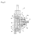
- Figure 2 shows a cross-sectional view of a II-II part in the above-described Figure 1 , a bearing part 2B for pivotally supporting a shaft part 3B constituting the rotor 3 is formed at an illustrated right side of the pump chamber 2A in the housing 2, and the shaft part 3B rotates integrally with the rotor part 3A.
- the cover 5 is provided at a left end of the pump chamber 2A, the rotor part 3A and an end surface of an illustrated left side of the vane 4 rotate slidingly contacting with this cover 5, and additionally, an end surface of a right side of the vane 4 rotates slidingly contacting with an inner surface of a bearing part 2B side of the pump chamber 2A.
- a bottom surface 9a of the groove 9 formed in the rotor 3 is formed slightly closer to a shaft part 3B side than the surface with which the pump chamber 2A and the vane 4 slidingly contact, and a gap is formed between the vane 4 and the bottom surface 9a.
- the shaft part 3B projects to the illustrated right side more than the bearing part 2B of the housing 2, couplings 10 rotated by an engine cam shaft are coupled at this projecting position, and the rotor 3 is rotated by a rotation of the cam shaft.
- an oil supply passage 11 through which the lubricating oil is flowed is formed at the shaft part 3B, and this oil supply passage 11 is connected to a hydraulic pump driven by an engine, which is not shown, through an oil supply pipe 12.
- the oil supply passage 11 includes: an axial direction oil supply hole 11a formed in an axial direction of the shaft part 3B; and a diameter direction oil supply hole 11b perforated in a diameter direction of the shaft part 3B, the hole 11b communicating with this axial direction oil supply hole 11a.
- an axial direction oil supply groove 11c constituting the oil supply passage 11 formed so as to make the pump chamber 2A and the diameter direction oil supply hole 11b communicate with a sliding part with the shaft part 3B.
- only one axial direction oil supply groove 11c is formed at a lower side of the bearing part 2B shown in Figure 2 , a left end of the axial direction oil supply groove 11c communicates with an inside of the pump chamber 2A, and a right end thereof is closed at a position of a right side from an opening of the diameter direction oil supply hole 11b by only a requirement.
- the vane pump 1 of the embodiment includes a gas passage 13 that makes the pump chamber 2A communicate with an outer space when the oil supply passage 11 is made to communicate with the pump chamber 2A by the rotation of the rotor 3, and more specifically, when the opening of the diameter direction oil supply hole 11b overlaps the axial direction oil supply groove 11c.
- the gas passage 13 includes two gas grooves 13a and 13a formed on an outer peripheral surface of a shaft part 3B of the rotor 3, each of the gas grooves 13a and 13a extends in a right direction shown in Figure 2 along an axial direction of the shaft part 3B from a position adjacent to the opening of the diameter direction oil supply hole 11b, and a right end of the each gas groove 13a is in communication with the outer space.
- each of the gas grooves 13a and 13a is closed at an adjacent position short of the opening of the diameter direction oil supply hole 11b without communicating therewith, the left end of each of the gas grooves 13a and 13a can be intermittently overlapped with the right end of the axial direction oil supply groove 11c closed at the position of the right side from the opening of the diameter direction oil supply hole 11b by only the requirement.
- a formation position of the gas groove 13a is provided at the same position as the opening of the axial direction oil supply hole 11b with respect to a circumferential direction of the shaft part 3B, whereby the diameter direction oil supply hole 11b of the oil supply passage 11 communicates with the axial direction oil supply groove 11c, and the gas groove 13a also communicates with the axial direction oil supply groove 11c.
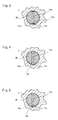
- Figure 3 is a cross-sectional view in a III-III portion in Figure 2 , and as shown in Figure 3 , the each gas groove 13a is formed to be a D shape in a cross section by planing the outer peripheral surface of the shaft part 3B in the embodiment, but a width of the gas groove 13a is formed smaller enough than the width of the axial direction oil supply groove 11c without being affected by the width thereof, and thereby a passage area of the gas groove 13a is set smaller as compared with the diameter direction gas hole of the conventional apparatus.
- the width of the each gas groove 13a is formed larger than that (diameter) of the opening of the diameter direction oil supply hole 11b based on the circumferential direction of the shaft part 3B, and that it is formed extending to positions anterior to and posterior to both end edges of the opening of the diameter direction oil supply hole 11b. If the width of the each gas groove 13a is set as described above, the gas groove 13a can be reliably made to communicate with the axial direction oil supply groove 11c even though a rotation is stopped in a state where the opening of the diameter direction oil supply hole 11b slightly communicates with the axial direction oil supply groove 11c.
- a cross-sectional shape of the gas groove 13a is not limited to the above-mentioned D shape in the cross section, and it may be an appropriate cross-sectional shape, such as a quadrangular shape in the cross section shown in Figure 4 and a triangular shape in the cross section shown in Figure 5 , in any case, it is preferable that a relation between the width of the each gas groove 13a and the opening of the diameter direction oil supply hole 11b is set as described above.
- the gas grooves 13a of the respective shapes can be formed by cutting after manufacturing the rotor 3, respectively, it is preferable to form the gas groove 13a at the same time when manufacturing the rotor 3 when the rotor 3 is manufactured by forging or sintering, thereby enabling to achieve reduction in manufacturing cost.
- the sucked gas is then compressed due to decrease of a volume of a space of the discharge passage 7 side, and it is discharged from the discharge passage 7.
- the lubricating oil is supplied to the oil supply passage 11 from the hydraulic pump driven by the engine through the oil supply pipe 12, and this lubricating oil flows into the pump chamber 2A when the diameter direction oil supply hole 11b and the axial direction oil supply groove 11c of the housing 2 communicate with each other by the rotation of the rotor 3.
- the lubricating oil having flowed into the pump chamber 2A flows into the hollow part 3a of the rotor part 3A from the gap between the bottom surface 9a of the groove 9 part formed at the rotor part 3A and the vane 4, this lubricating oil spouts in the pump chamber 2A from a gap between the rotor part 3A and the groove 9, and from a gap between the vane 4 and the cover 5 to lubricate these gaps and to seal the pump chamber 2A, and after that, the lubricating oil is discharged from the discharge passage 7 along with the gas.
- the rotor 3 stops according to the engine stop, and air intake from the servo unit finishes.
- the space of the intake air passage 6 side partitioned by the vane 4 stops remained in a negative pressure state by the stop of the rotor 3, if the opening of the diameter direction oil supply hole 11b and the axial direction oil supply groove 11c do not correspond to each other at this time, the lubricating oil in the axial direction oil supply hole 11a does not flow into the pump chamber 2A.
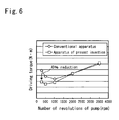
- Figure 6 is a test result graph obtained by testing relations between the number of revolutions and driving torque, and 0 marks indicate the conventional apparatus, and ⁇ marks indicate the apparatus of the present invention.
- a gas passage of the conventional apparatus includes a diameter direction gas hole, and a diameter of the gas hole is set to be minimum 1.5 millimeters in consideration of preventing clogging, thus resulting in 1.77 mm 2 of passage area of the conventional gas passage.
- the gas passage 13 of the present invention is the groove-shaped gas groove 13a having the cross-sectional shape shown in Figures 3 to 5 , clogging thereof does not easily occur as compared with a conventional hole shape, and thus the passage area of the gas passage 13 is set to be 0.91 mm 2 , which is smaller than the passage area of the conventional gas passage. It is to be noted that although the gas groove 13a of the D shape in the cross section shown in Figure 3 was used for the test, equivalent test results have been obtained also when using the other cross-sectional shapes.
- driving torque increases as the number of revolutions of the engine becomes not more than 1000 revolutions in the conventional apparatus (0). This is because an amount of air sucked in the pump chamber 2A increases as the number of revolutions of the engine becomes not more than 1000 revolutions, the air sucked along with the rotation of the vane 4 is again discharged to an outside of the pump chamber 2A, and thereby driving torque becomes larger along with the increase of the amount of air sucked in the pump chamber 2A.
- the passage area of the gas hole 13a is reduced as the example of the present invention ( ⁇ ) in contrast with the above-described conventional apparatus, increase of the driving torque can be suppressed even though the number of revolutions of the engine decreases. This shows that the amount of air sucked in the pump chamber 2A can be reduced.
Landscapes
- Engineering & Computer Science (AREA)
- Mechanical Engineering (AREA)
- General Engineering & Computer Science (AREA)
- Rotary Pumps (AREA)
- Applications Or Details Of Rotary Compressors (AREA)
Abstract
Description
- The present invention relates to a vane pump and, more particularly, to a vane pump in which an oil supply passage through which a lubricating oil flows is formed inside a rotor, and in which the lubricating oil is intermittently supplied in a pump chamber by a rotation of the rotor.
- Conventionally, a vane pump has been known, which includes: a housing including a substantially circular pump chamber; a rotor that rotates about a position eccentric with respect to a center of the pump chamber; a vane that is rotated by the rotor and that always partitions the pump chamber into a plurality of spaces; an oil supply passage that intermittently communicates with the pump chamber by the rotation of the rotor; and a gas passage that makes the pump chamber and an outer space communicate with each other when the oil supply passage communicates with the pump chamber by the rotation of the rotor, wherein
the oil supply passage includes: a diameter direction oil supply hole provided at a shaft part of the rotor in a diameter direction thereof; and an axial direction oil supply groove that is provided in the housing to communicate with the pump chamber, and with which an opening of the diameter direction oil supply hole is made to intermittently overlappingly communicate by the rotation of the rotor. (Patent Document 1)
In the vane pump, the gas passage includes: a diameter direction gas hole that is provided at the shaft part of the rotor in the diameter direction thereof to communicate with the oil supply passage; and an axial direction gas groove that is provided in the housing to communicate with the outer space, and with which an opening of the diameter direction gas hole is made to intermittently overlappingly communicate by the rotation of the rotor, wherein the diameter direction gas hole is made to communicate with the axial direction gas groove when the diameter direction oil supply hole is made to communicate with the axial direction oil supply groove. - In the above-described vane pump, when the rotor stops in a state where the diameter direction oil supply hole of the oil supply passage is in communication with the axial direction oil supply groove, the lubricating oil inside the oil supply passage is drawn into the pump chamber by a negative pressure thereinside. If a large amount of lubricating oil is then drawn into the pump chamber, an excessive load is added to the vanes when the vane pump is subsequently started in order to discharge the lubricating oil, which may cause a damage on the vane.
However, in the vane pump having the above-described configuration, when the rotor stops in the state where the diameter direction oil supply hole of the oil supply passage is in communication with the axial direction oil supply groove, the diameter direction gas hole of the gas passage is adapted to communicate with the axial direction gas groove at the same time, so as to allow the air of the outer space to flow into the pump chamber through the gas passage. Hence, since the negative pressure in the pump chamber can be eliminated by allowing the air of the outer space to flow into the pump chamber, a large amount of lubricating oil can be prevented from entering the pump chamber. -
- Patent Document 1: Japanese Patent Laid-Open No.
2006-226164 - However, in the above-described vane pump, it turned out that when a hydraulic pressure of the lubricating oil supplied from the hydraulic pump to the oil supply passage was low such as at the time of engine idling, the air of the outer space was sucked into the pump chamber from the gas passage, and thereby engine driving torque was increased.
By the way, a passage area of the diameter direction gas hole constituting the gas passage is set to be as small passage area as possible in order to reduce the leakage of the lubricating oil to the outer space through the gas passage, i.e., to an internal space of an engine when the hydraulic pressure of the lubricating oil supplied from the hydraulic pump to the oil supply passage is high. On the other hand, since the diameter direction gas hole is the hole perforated in a diameter direction of the rotor, a much smaller hole diameter thereof may easily cause the hole to be clogged.
Hence, in the vane pump configured as described above, there has been a certain limit in reducing the passage area of the diameter direction gas hole constituting the gas passage. - Since the axial direction gas groove is a "groove" in contrast with the above-mentioned diameter direction gas hole, clogging thereof is less likely to occur than in a through-hole, thus enabling to reduce the passage area of the axial direction gas groove compared with the diameter direction gas hole. However, since a width of the axial direction gas groove must be made to correspond to that of the axial direction oil supply groove in a case of a configuration of
Patent Document 1, there has been also a certain limit in reducing the passage area of the axial direction gas groove.
To explain this in more detail, since the diameter direction gas hole must be in communication with the axial direction gas groove at the same time when the rotor stops in a state where the diameter direction oil supply hole is in communication with the axial direction oil supply groove, the width of the axial direction gas groove must be certainly set to be a width with which the diameter direction gas hole is in a state of being in communication overlappingly with this axial direction gas groove while the diameter direction oil supply hole is in communication overlappingly with the axial direction oil supply groove. Namely, the width of the axial direction gas groove must be made to correspond to that of the axial direction oil supply groove.
However, the width of the axial direction oil supply groove must be set to be a width with which a required amount of lubricating oil can be supplied to the pump chamber in consideration of an overlap time of the axial direction oil supply groove with the diameter direction oil supply hole that crosses the groove. Hence, the width of this axial direction oil supply groove cannot be made smaller without any reason, and as a result of it, the width of the axial direction gas groove has been unable to be made smaller, either.
In view of such conditions, the present invention provides a vane pump in which the passage area of the gas passage can be set smaller as compared with a conventional vane pump to prevent the air from being sucked in the pump chamber from the gas passage as much as possible, thereby enabling to prevent engine driving torque from increasing. - Namely, the present invention is a vane pump including: a housing including a substantially circular pump chamber; a rotor that rotates about a position eccentric with respect to a center of the pump chamber; a vane that is rotated by the rotor and that always partitions the pump chamber into a plurality of spaces; an oil supply passage that intermittently communicates with the pump chamber by the rotation of the rotor; and a gas passage that makes the pump chamber and an outer space communicate with each other when the oil supply passage communicates with the pump chamber by the rotation of the rotor, wherein
the oil supply passage includes: a diameter direction oil supply hole provided at a shaft part of the rotor in a diameter direction thereof; and an axial direction oil supply groove that is provided in the housing to communicate with the pump chamber, and with which an opening of the diameter direction oil supply hole is made to intermittently overlappingly communicate by the rotation of the rotor, and wherein
the gas passage is comprised of a gas groove whose one end is made to communicate with the outer space, the gas groove being formed on an outer peripheral surface of the rotor, and the other end of this gas groove is made to intermittently overlappingly communicate with the axial direction oil supply groove by the rotation of the rotor. - In the present invention, the gas passage is comprised of a gas groove whose one end is made to communicate with an outer space, the gas groove being formed on an outer peripheral surface of the rotor. Additionally, since the other end of this gas groove is made to intermittently overlappingly communicate with the axial direction oil supply groove by a rotation of the rotor, it is not necessary to make a width of this gas groove correspond to that of the axial direction oil supply groove as in a conventional apparatus. Namely, since the gas groove has only to communicate with the axial direction oil supply groove at the same time when the rotor stops in the state where the diameter direction oil supply hole is in communication with the axial direction oil supply groove, it is not necessary to make the width of the gas groove correspond to that of the axial direction oil supply groove.
Additionally, as mentioned above, clogging of the groove is less likely to occur than the through-hole, thus enabling to reduce the passage area of the groove as compared with a conventional diameter direction gas hole. Hence, the air is prevented from being sucked in the pump chamber from the gas passage as much as possible, thus enabling to prevent engine driving torque from increasing. -
- [
Figure 1] Figure 1 is an elevational view of a vane pump showing an embodiment of the present invention. - [
Figure 2] Figure 2 is a cross-sectional view taken along a line II-II inFigure 1 . - [
Figure 3] Figure 3 is a cross-sectional view taken along a line III-III inFigure 2 . - [
Figure 4] Figure 4 is a cross-sectional view in a portion similar toFigure 3 showing a second embodiment of the present invention. - [
Figure 5] Figure 5 is a cross-sectional view in the portion similar toFigure 3 showing a third embodiment of the present invention. - [
Figure 6] Figure 6 is a test result graph obtained by testing a relation between the number of revolutions and driving torque. - Hereinafter, when describing an embodiment shown in drawings of the present invention,
Figures 1 and2 show avane pump 1 according to the present invention, and thisvane pump 1 is fixed to a side surface of an engine of an automobile, which is not shown, to generate a negative pressure in a servo unit for a brake system, which is not shown.
Thisvane pump 1 includes: ahousing 2 in which a substantiallycircular pump chamber 2A is formed; arotor 3 that is rotated by an engine drive force about a position eccentric with respect to a center of thepump chamber 2A; avane 4 that is rotated by therotor 3 and that always partitions thepump chamber 2A into a plurality of spaces; and acover 5 that closes thepump chamber 2A.
Thehousing 2 is provided with anintake air passage 6 that communicates with the servo unit for the brake to suck a gas from the servo unit, theintake air passage 6 being located at an upper part of thepump chamber 2A, and adischarge passage 7 for discharging the gas sucked from the servo unit, thedischarge passage 7 being located at a lower part of thepump chamber 2A, respectively. Additionally, theintake air passage 6 is provided with acheck valve 8 in order to hold a negative pressure in the servo unit particularly when the engine is stopped. - The
rotor 3 includes acylindrical rotor part 3A that rotates in thepump chamber 2A, an outer periphery of therotor part 3A is provided so as to contact with an inner peripheral surface of thepump chamber 2A, theintake air passage 6 is located at an upstream side with respect to a rotation of therotor part 3A, and thedischarge passage 7 is formed closer to a downstream side than therotor part 3A.
In addition, a groove 9 is formed in a diameter direction at therotor part 3A, and thevane 4 is slidably moved in a direction perpendicular to an axial direction of therotor 3 along the groove 9. Additionally, a lubricating oil from an oil supply passage, which will be described hereinafter, flows between ahollow part 3a formed in a center of therotor part 3A and thevane 4.
Further,caps 4a are provided at both ends of thevane 4, and thepump chamber 2A is always partitioned into two or three spaces by rotating thesecaps 4a while always sliding them on the inner peripheral surface of thepump chamber 2A.
Specifically, thepump chamber 2A is partitioned by thevane 4 into an illustrated horizontal direction in a state ofFigure 1 , further, the pump chamber is partitioned by therotor part 3A into a vertical direction in a space of an illustrated right side, and therefore, thepump chamber 2A is partitioned into a total of three spaces.
When thevane 4 rotates to the vicinity of a position connecting the center of thepump chamber 2A and a rotation center of therotor 3 by the rotation of therotor 3 from this state ofFigure 1 , thepump chamber 2A is partitioned into two spaces: a space of anintake air passage 6 side; and a space of adischarge passage 7 side. -
Figure 2 shows a cross-sectional view of a II-II part in the above-describedFigure 1 , abearing part 2B for pivotally supporting ashaft part 3B constituting therotor 3 is formed at an illustrated right side of thepump chamber 2A in thehousing 2, and theshaft part 3B rotates integrally with therotor part 3A.
In addition, thecover 5 is provided at a left end of thepump chamber 2A, therotor part 3A and an end surface of an illustrated left side of thevane 4 rotate slidingly contacting with thiscover 5, and additionally, an end surface of a right side of thevane 4 rotates slidingly contacting with an inner surface of a bearingpart 2B side of thepump chamber 2A.
In addition, abottom surface 9a of the groove 9 formed in therotor 3 is formed slightly closer to ashaft part 3B side than the surface with which thepump chamber 2A and thevane 4 slidingly contact, and a gap is formed between thevane 4 and thebottom surface 9a.
Further, theshaft part 3B projects to the illustrated right side more than the bearingpart 2B of thehousing 2,couplings 10 rotated by an engine cam shaft are coupled at this projecting position, and therotor 3 is rotated by a rotation of the cam shaft. - Additionally, an
oil supply passage 11 through which the lubricating oil is flowed is formed at theshaft part 3B, and thisoil supply passage 11 is connected to a hydraulic pump driven by an engine, which is not shown, through anoil supply pipe 12.
Theoil supply passage 11 includes: an axial directionoil supply hole 11a formed in an axial direction of theshaft part 3B; and a diameter directionoil supply hole 11b perforated in a diameter direction of theshaft part 3B, thehole 11b communicating with this axial directionoil supply hole 11a.
In addition, at the bearingpart 2B of thehousing 2, formed is an axial directionoil supply groove 11c constituting theoil supply passage 11 formed so as to make thepump chamber 2A and the diameter directionoil supply hole 11b communicate with a sliding part with theshaft part 3B. In the embodiment, only one axial directionoil supply groove 11c is formed at a lower side of the bearingpart 2B shown inFigure 2 , a left end of the axial directionoil supply groove 11c communicates with an inside of thepump chamber 2A, and a right end thereof is closed at a position of a right side from an opening of the diameter directionoil supply hole 11b by only a requirement.
According to this configuration, when an opening of the diameter directionoil supply hole 11b overlaps and communicates with the axial directionoil supply groove 11c as shown inFigure 2 , the lubricating oil from the axial directionoil supply hole 11a flows into thepump chamber 2A through the diameter directionoil supply hole 11b and the axial directionoil supply groove 11c, and then flows into thehollow part 3a of therotor 3 from the gap between thevane 4 and thebottom surface 9a of the groove 9. - Additionally, the
vane pump 1 of the embodiment includes agas passage 13 that makes thepump chamber 2A communicate with an outer space when theoil supply passage 11 is made to communicate with thepump chamber 2A by the rotation of therotor 3, and more specifically, when the opening of the diameter directionoil supply hole 11b overlaps the axial directionoil supply groove 11c.
Thegas passage 13 includes twogas grooves shaft part 3B of therotor 3, each of thegas grooves Figure 2 along an axial direction of theshaft part 3B from a position adjacent to the opening of the diameter directionoil supply hole 11b, and a right end of the eachgas groove 13a is in communication with the outer space.
On the other hand, although a left end of each of thegas grooves oil supply hole 11b without communicating therewith, the left end of each of thegas grooves oil supply groove 11c closed at the position of the right side from the opening of the diameter directionoil supply hole 11b by only the requirement.
Namely, a formation position of thegas groove 13a is provided at the same position as the opening of the axial directionoil supply hole 11b with respect to a circumferential direction of theshaft part 3B, whereby the diameter directionoil supply hole 11b of theoil supply passage 11 communicates with the axial directionoil supply groove 11c, and thegas groove 13a also communicates with the axial directionoil supply groove 11c. -
Figure 3 is a cross-sectional view in a III-III portion inFigure 2 , and as shown inFigure 3 , the eachgas groove 13a is formed to be a D shape in a cross section by planing the outer peripheral surface of theshaft part 3B in the embodiment, but a width of thegas groove 13a is formed smaller enough than the width of the axial directionoil supply groove 11c without being affected by the width thereof, and thereby a passage area of thegas groove 13a is set smaller as compared with the diameter direction gas hole of the conventional apparatus.
On the other hand, it is preferable that the width of the eachgas groove 13a is formed larger than that (diameter) of the opening of the diameter directionoil supply hole 11b based on the circumferential direction of theshaft part 3B, and that it is formed extending to positions anterior to and posterior to both end edges of the opening of the diameter directionoil supply hole 11b. If the width of the eachgas groove 13a is set as described above, thegas groove 13a can be reliably made to communicate with the axial directionoil supply groove 11c even though a rotation is stopped in a state where the opening of the diameter directionoil supply hole 11b slightly communicates with the axial directionoil supply groove 11c. - Although a cross-sectional shape of the
gas groove 13a is not limited to the above-mentioned D shape in the cross section, and it may be an appropriate cross-sectional shape, such as a quadrangular shape in the cross section shown inFigure 4 and a triangular shape in the cross section shown inFigure 5 , in any case, it is preferable that a relation between the width of the eachgas groove 13a and the opening of the diameter directionoil supply hole 11b is set as described above.
Although it goes without saying that thegas grooves 13a of the respective shapes can be formed by cutting after manufacturing therotor 3, respectively, it is preferable to form thegas groove 13a at the same time when manufacturing therotor 3 when therotor 3 is manufactured by forging or sintering, thereby enabling to achieve reduction in manufacturing cost. - To explain operations of the
vane pump 1 having the above-described configuration hereinafter, similarly to aconventional vane pump 1, when therotor 3 is rotated by actuation of the engine, thevane 4 also rotates reciprocating in the groove 9 of therotor 3 along with the actuation, and a volume of a space of thepump chamber 2A partitioned by thevane 4 changes according to the rotation of therotor 3.
As a result of it, a volume in a space of theintake air passage 6 side partitioned by thevane 4 increases to generate a negative pressure in thepump chamber 2A, and a gas is sucked from the servo unit through theintake air passage 6 to generate a negative pressure in the servo unit. Additionally, the sucked gas is then compressed due to decrease of a volume of a space of thedischarge passage 7 side, and it is discharged from thedischarge passage 7. Meanwhile, when thevane pump 1 is started, the lubricating oil is supplied to theoil supply passage 11 from the hydraulic pump driven by the engine through theoil supply pipe 12, and this lubricating oil flows into thepump chamber 2A when the diameter directionoil supply hole 11b and the axial directionoil supply groove 11c of thehousing 2 communicate with each other by the rotation of therotor 3.
The lubricating oil having flowed into thepump chamber 2A flows into thehollow part 3a of therotor part 3A from the gap between thebottom surface 9a of the groove 9 part formed at therotor part 3A and thevane 4, this lubricating oil spouts in thepump chamber 2A from a gap between therotor part 3A and the groove 9, and from a gap between thevane 4 and thecover 5 to lubricate these gaps and to seal thepump chamber 2A, and after that, the lubricating oil is discharged from thedischarge passage 7 along with the gas. - When the engine is stopped from the above-described operational state, the
rotor 3 stops according to the engine stop, and air intake from the servo unit finishes.
Here, although the space of theintake air passage 6 side partitioned by thevane 4 stops remained in a negative pressure state by the stop of therotor 3, if the opening of the diameter directionoil supply hole 11b and the axial directionoil supply groove 11c do not correspond to each other at this time, the lubricating oil in the axial directionoil supply hole 11a does not flow into thepump chamber 2A.
In contrast with this, when therotor 3 stops in a state where the opening of the diameter directionoil supply hole 11b and the axial directionoil supply groove 11c correspond to each other, a large amount of lubricating oil in theoil supply passage 11 tends to flow into thepump chamber 2A due to the negative pressure in thepump chamber 2A.
However, since thegas groove 13a corresponds to the axial directionoil supply groove 11c at the same time when the opening of the diameter directionoil supply hole 11b and the axial directionoil supply groove 11c correspond to each other, the atmosphere flows into thepump chamber 2A from thisgas hole 13a to eliminate the negative pressure therein, thereby enabling to prevent the large amount of lubricating oil from flowing into thepump chamber 2A. -
Figure 6 is a test result graph obtained by testing relations between the number of revolutions and driving torque, and 0 marks indicate the conventional apparatus, and □ marks indicate the apparatus of the present invention. InFigure 6 , a gas passage of the conventional apparatus includes a diameter direction gas hole, and a diameter of the gas hole is set to be minimum 1.5 millimeters in consideration of preventing clogging, thus resulting in 1.77 mm2 of passage area of the conventional gas passage.
In contrast with this, since thegas passage 13 of the present invention is the groove-shapedgas groove 13a having the cross-sectional shape shown inFigures 3 to 5 , clogging thereof does not easily occur as compared with a conventional hole shape, and thus the passage area of thegas passage 13 is set to be 0.91 mm2, which is smaller than the passage area of the conventional gas passage. It is to be noted that although thegas groove 13a of the D shape in the cross section shown inFigure 3 was used for the test, equivalent test results have been obtained also when using the other cross-sectional shapes. - As can be understood from the above-described test results, driving torque increases as the number of revolutions of the engine becomes not more than 1000 revolutions in the conventional apparatus (0). This is because an amount of air sucked in the
pump chamber 2A increases as the number of revolutions of the engine becomes not more than 1000 revolutions, the air sucked along with the rotation of thevane 4 is again discharged to an outside of thepump chamber 2A, and thereby driving torque becomes larger along with the increase of the amount of air sucked in thepump chamber 2A.
When the passage area of thegas hole 13a is reduced as the example of the present invention (□) in contrast with the above-described conventional apparatus, increase of the driving torque can be suppressed even though the number of revolutions of the engine decreases. This shows that the amount of air sucked in thepump chamber 2A can be reduced. - Note that it goes without saying that although the above-described each embodiment has been described using the
vane pump 1 including a sheet ofvane 4, the conventionally knownvane pump 1 including a plurality ofvanes 4 is also applicable, and additionally, an application of thevane pump 1 is not limited to generate a negative pressure in a servo unit. -
- 1
- Vane pump
- 2
- Housing
- 2A
- Pump chamber
- 2B
- Bearing part
- 3
- Rotor
- 3A
- Rotor part
- 3B
- Shaft part
- 4
- Vane
- 11
- Oil supply passage
- 11a
- Axial direction oil supply hole
- 11b
- Diameter direction oil supply hole
- 11c
- Axial direction oil supply groove
- 13
- Gas passage
- 13a
- Gas groove
Claims (4)
- A vane pump comprising: a housing comprising a substantially circular pump chamber; a rotor that rotates about a position eccentric with respect to a center of the pump chamber; a vane that is rotated by the rotor and that always partitions the pump chamber into a plurality of spaces; an oil supply passage that intermittently communicates with the pump chamber by the rotation of the rotor; and a gas passage that makes the pump chamber and an outer space communicate with each other when the oil supply passage communicates with the pump chamber by the rotation of the rotor, wherein
the oil supply passage further comprises: a diameter direction oil supply hole provided at a shaft part of the rotor in a diameter direction thereof; and an axial direction oil supply groove that is provided in the housing to communicate with the pump chamber, and with which an opening of the diameter direction oil supply hole is made to intermittently overlappingly communicate by the rotation of the rotor, the vane pump wherein
the gas passage is comprised of a gas groove whose one end is made to communicate with the outer space, the gas groove being formed on an outer peripheral surface of the rotor, and the other end of this gas groove is made to intermittently overlappingly communicate with the axial direction oil supply groove by the rotation of the rotor. - The vane pump according to claim 1, wherein a width of the gas groove is formed larger than that of the opening of the diameter direction oil supply hole based on a circumferential direction of the shaft part of the rotor, and it is formed extending to positions anterior to and posterior to both end edges of the opening of the diameter direction oil supply hole.
- The vane pump according to claim 1 or 2, wherein a cross-sectional shape of the gas groove is any of a D shape in a cross section formed by planing the outer peripheral surface of the shaft part of the rotor, a quadrangular shape in the cross section, and a triangular shape in the cross section.
- The vane pump according to any of claims 1 to 3, wherein the gas groove is formed at the same time when manufacturing the rotor.
Applications Claiming Priority (2)
| Application Number | Priority Date | Filing Date | Title |
|---|---|---|---|
| JP2010102248A JP5589532B2 (en) | 2010-04-27 | 2010-04-27 | Vane pump |
| PCT/JP2010/070443 WO2011135746A1 (en) | 2010-04-27 | 2010-11-17 | Vane pump |
Publications (3)
| Publication Number | Publication Date |
|---|---|
| EP2397696A1 true EP2397696A1 (en) | 2011-12-21 |
| EP2397696A4 EP2397696A4 (en) | 2012-08-29 |
| EP2397696B1 EP2397696B1 (en) | 2015-08-12 |
Family
ID=44861079
Family Applications (1)
| Application Number | Title | Priority Date | Filing Date |
|---|---|---|---|
| EP10846808.3A Not-in-force EP2397696B1 (en) | 2010-04-27 | 2010-11-17 | Vane pump |
Country Status (7)
| Country | Link |
|---|---|
| US (1) | US8459973B2 (en) |
| EP (1) | EP2397696B1 (en) |
| JP (1) | JP5589532B2 (en) |
| KR (1) | KR101280978B1 (en) |
| CN (1) | CN102365461B (en) |
| RU (1) | RU2480627C1 (en) |
| WO (1) | WO2011135746A1 (en) |
Cited By (2)
| Publication number | Priority date | Publication date | Assignee | Title |
|---|---|---|---|---|
| WO2014063681A1 (en) * | 2012-10-22 | 2014-05-01 | Ixetic Bad Homburg Gmbh | Intermittent coupling oiling |
| WO2017028914A1 (en) * | 2015-08-19 | 2017-02-23 | Pierburg Pump Technology Gmbh | Lubricated automotive vacuum pump |
Families Citing this family (7)
| Publication number | Priority date | Publication date | Assignee | Title |
|---|---|---|---|---|
| KR101484271B1 (en) | 2011-12-22 | 2015-01-19 | 주식회사 만도 | Electric power steering system and method for verifying steering angle of the same |
| JP5963548B2 (en) | 2012-06-05 | 2016-08-03 | カルソニックカンセイ株式会社 | Gas compressor |
| DE202014005520U1 (en) * | 2014-07-08 | 2015-10-09 | Joma-Polytec Gmbh | Vane pump for generating a negative pressure |
| JP6406605B2 (en) * | 2014-10-03 | 2018-10-17 | 大豊工業株式会社 | Vacuum pump |
| EP3032105B1 (en) * | 2014-12-12 | 2021-05-19 | Pierburg Pump Technology GmbH | Mechanical motor vehicle vacuum pump |
| KR101909783B1 (en) * | 2016-02-11 | 2018-10-18 | 김경수 | Rotary vane Pump or vacuum pump in motion of synchronous rotation with casing |
| JP6382877B2 (en) * | 2016-03-24 | 2018-08-29 | 大豊工業株式会社 | Vane pump |
Citations (6)
| Publication number | Priority date | Publication date | Assignee | Title |
|---|---|---|---|---|
| JPS58214692A (en) * | 1982-06-07 | 1983-12-13 | Mitsubishi Electric Corp | Scroll compressor |
| JP2006118424A (en) * | 2004-10-21 | 2006-05-11 | Toyota Motor Corp | Vacuum pump |
| WO2006122516A1 (en) * | 2005-05-19 | 2006-11-23 | Ixetic Hückeswagen Gmbh | Vane-cell pump |
| WO2007000129A1 (en) * | 2005-06-25 | 2007-01-04 | Ixetic Hückeswagen Gmbh | Pump |
| EP1850007A1 (en) * | 2005-02-16 | 2007-10-31 | Taiho Kogyo Co., Ltd. | Vane pump |
| WO2009063741A1 (en) * | 2007-11-14 | 2009-05-22 | Daikin Industries, Ltd. | Enclosed compressor |
Family Cites Families (5)
| Publication number | Priority date | Publication date | Assignee | Title |
|---|---|---|---|---|
| JP2809899B2 (en) | 1991-09-06 | 1998-10-15 | 株式会社東芝 | Incore tightening nut handling tool |
| JPH0566287U (en) * | 1992-02-13 | 1993-09-03 | 株式会社ユニシアジェックス | Vane pump |
| JPH09209927A (en) * | 1996-01-29 | 1997-08-12 | Toyota Autom Loom Works Ltd | Compressor |
| JP4733356B2 (en) * | 2004-03-10 | 2011-07-27 | トヨタ自動車株式会社 | Vane pump for gas and operation method thereof |
| JP2009185699A (en) * | 2008-02-06 | 2009-08-20 | Toyota Motor Corp | Vacuum pump |
-
2010
- 2010-04-27 JP JP2010102248A patent/JP5589532B2/en not_active Expired - Fee Related
- 2010-11-17 WO PCT/JP2010/070443 patent/WO2011135746A1/en not_active Ceased
- 2010-11-17 KR KR1020117020297A patent/KR101280978B1/en not_active Expired - Fee Related
- 2010-11-17 EP EP10846808.3A patent/EP2397696B1/en not_active Not-in-force
- 2010-11-17 US US13/138,451 patent/US8459973B2/en not_active Expired - Fee Related
- 2010-11-17 CN CN201080014873.8A patent/CN102365461B/en not_active Expired - Fee Related
- 2010-11-17 RU RU2011148264/06A patent/RU2480627C1/en not_active IP Right Cessation
Patent Citations (6)
| Publication number | Priority date | Publication date | Assignee | Title |
|---|---|---|---|---|
| JPS58214692A (en) * | 1982-06-07 | 1983-12-13 | Mitsubishi Electric Corp | Scroll compressor |
| JP2006118424A (en) * | 2004-10-21 | 2006-05-11 | Toyota Motor Corp | Vacuum pump |
| EP1850007A1 (en) * | 2005-02-16 | 2007-10-31 | Taiho Kogyo Co., Ltd. | Vane pump |
| WO2006122516A1 (en) * | 2005-05-19 | 2006-11-23 | Ixetic Hückeswagen Gmbh | Vane-cell pump |
| WO2007000129A1 (en) * | 2005-06-25 | 2007-01-04 | Ixetic Hückeswagen Gmbh | Pump |
| WO2009063741A1 (en) * | 2007-11-14 | 2009-05-22 | Daikin Industries, Ltd. | Enclosed compressor |
Non-Patent Citations (1)
| Title |
|---|
| See also references of WO2011135746A1 * |
Cited By (4)
| Publication number | Priority date | Publication date | Assignee | Title |
|---|---|---|---|---|
| WO2014063681A1 (en) * | 2012-10-22 | 2014-05-01 | Ixetic Bad Homburg Gmbh | Intermittent coupling oiling |
| US9915264B2 (en) | 2012-10-22 | 2018-03-13 | Magna Powertrain Bad Homburg GmbH | Intermittent coupling oiling |
| DE112013005092B4 (en) * | 2012-10-22 | 2021-03-04 | Hanon Systems Efp Deutschland Gmbh | Clutch lubrication |
| WO2017028914A1 (en) * | 2015-08-19 | 2017-02-23 | Pierburg Pump Technology Gmbh | Lubricated automotive vacuum pump |
Also Published As
| Publication number | Publication date |
|---|---|
| JP2011231675A (en) | 2011-11-17 |
| WO2011135746A1 (en) | 2011-11-03 |
| KR20110140120A (en) | 2011-12-30 |
| EP2397696A4 (en) | 2012-08-29 |
| CN102365461B (en) | 2014-06-25 |
| JP5589532B2 (en) | 2014-09-17 |
| CN102365461A (en) | 2012-02-29 |
| EP2397696B1 (en) | 2015-08-12 |
| RU2480627C1 (en) | 2013-04-27 |
| US8459973B2 (en) | 2013-06-11 |
| US20120076682A1 (en) | 2012-03-29 |
| KR101280978B1 (en) | 2013-07-08 |
Similar Documents
| Publication | Publication Date | Title |
|---|---|---|
| EP2397696B1 (en) | Vane pump | |
| US8382462B2 (en) | Vane pump with circulating oil supply passage | |
| EP2602487B1 (en) | Vane pump | |
| CN103807166B (en) | Scroll compressor having a plurality of scroll members | |
| EP1850008B1 (en) | Vane pump | |
| CN103541898A (en) | Variable displacement vane pump with enhanced discharge port | |
| CN203098281U (en) | Scroll compressor having a plurality of scroll members | |
| CN102459815B (en) | Vane pump with improved rotor and vane extension ring | |
| CN109923313B (en) | Vane pump | |
| US8936452B2 (en) | Pump housing | |
| US10823170B2 (en) | Transmission with double-flow sliding vane pump | |
| CN107923400A (en) | The automobile vacuum pump of lubrication |
Legal Events
| Date | Code | Title | Description |
|---|---|---|---|
| PUAI | Public reference made under article 153(3) epc to a published international application that has entered the european phase |
Free format text: ORIGINAL CODE: 0009012 |
|
| AK | Designated contracting states |
Kind code of ref document: A1 Designated state(s): AL AT BE BG CH CY CZ DE DK EE ES FI FR GB GR HR HU IE IS IT LI LT LU LV MC MK MT NL NO PL PT RO RS SE SI SK SM TR |
|
| A4 | Supplementary search report drawn up and despatched |
Effective date: 20120801 |
|
| RIC1 | Information provided on ipc code assigned before grant |
Ipc: F04C 29/02 20060101ALI20120726BHEP Ipc: F04C 18/344 20060101AFI20120726BHEP Ipc: F04C 25/02 20060101ALI20120726BHEP |
|
| 17P | Request for examination filed |
Effective date: 20110915 |
|
| DAX | Request for extension of the european patent (deleted) | ||
| GRAP | Despatch of communication of intention to grant a patent |
Free format text: ORIGINAL CODE: EPIDOSNIGR1 |
|
| INTG | Intention to grant announced |
Effective date: 20150401 |
|
| GRAS | Grant fee paid |
Free format text: ORIGINAL CODE: EPIDOSNIGR3 |
|
| GRAA | (expected) grant |
Free format text: ORIGINAL CODE: 0009210 |
|
| AK | Designated contracting states |
Kind code of ref document: B1 Designated state(s): AL AT BE BG CH CY CZ DE DK EE ES FI FR GB GR HR HU IE IS IT LI LT LU LV MC MK MT NL NO PL PT RO RS SE SI SK SM TR |
|
| REG | Reference to a national code |
Ref country code: GB Ref legal event code: FG4D |
|
| REG | Reference to a national code |
Ref country code: CH Ref legal event code: EP |
|
| REG | Reference to a national code |
Ref country code: AT Ref legal event code: REF Ref document number: 742412 Country of ref document: AT Kind code of ref document: T Effective date: 20150815 |
|
| REG | Reference to a national code |
Ref country code: IE Ref legal event code: FG4D |
|
| REG | Reference to a national code |
Ref country code: DE Ref legal event code: R096 Ref document number: 602010026710 Country of ref document: DE |
|
| REG | Reference to a national code |
Ref country code: LT Ref legal event code: MG4D |
|
| REG | Reference to a national code |
Ref country code: AT Ref legal event code: MK05 Ref document number: 742412 Country of ref document: AT Kind code of ref document: T Effective date: 20150812 |
|
| REG | Reference to a national code |
Ref country code: NL Ref legal event code: MP Effective date: 20150812 |
|
| PG25 | Lapsed in a contracting state [announced via postgrant information from national office to epo] |
Ref country code: GR Free format text: LAPSE BECAUSE OF FAILURE TO SUBMIT A TRANSLATION OF THE DESCRIPTION OR TO PAY THE FEE WITHIN THE PRESCRIBED TIME-LIMIT Effective date: 20151113 Ref country code: NO Free format text: LAPSE BECAUSE OF FAILURE TO SUBMIT A TRANSLATION OF THE DESCRIPTION OR TO PAY THE FEE WITHIN THE PRESCRIBED TIME-LIMIT Effective date: 20151112 Ref country code: LV Free format text: LAPSE BECAUSE OF FAILURE TO SUBMIT A TRANSLATION OF THE DESCRIPTION OR TO PAY THE FEE WITHIN THE PRESCRIBED TIME-LIMIT Effective date: 20150812 Ref country code: LT Free format text: LAPSE BECAUSE OF FAILURE TO SUBMIT A TRANSLATION OF THE DESCRIPTION OR TO PAY THE FEE WITHIN THE PRESCRIBED TIME-LIMIT Effective date: 20150812 Ref country code: FI Free format text: LAPSE BECAUSE OF FAILURE TO SUBMIT A TRANSLATION OF THE DESCRIPTION OR TO PAY THE FEE WITHIN THE PRESCRIBED TIME-LIMIT Effective date: 20150812 |
|
| PG25 | Lapsed in a contracting state [announced via postgrant information from national office to epo] |
Ref country code: RS Free format text: LAPSE BECAUSE OF FAILURE TO SUBMIT A TRANSLATION OF THE DESCRIPTION OR TO PAY THE FEE WITHIN THE PRESCRIBED TIME-LIMIT Effective date: 20150812 Ref country code: AT Free format text: LAPSE BECAUSE OF FAILURE TO SUBMIT A TRANSLATION OF THE DESCRIPTION OR TO PAY THE FEE WITHIN THE PRESCRIBED TIME-LIMIT Effective date: 20150812 Ref country code: ES Free format text: LAPSE BECAUSE OF FAILURE TO SUBMIT A TRANSLATION OF THE DESCRIPTION OR TO PAY THE FEE WITHIN THE PRESCRIBED TIME-LIMIT Effective date: 20150812 Ref country code: PL Free format text: LAPSE BECAUSE OF FAILURE TO SUBMIT A TRANSLATION OF THE DESCRIPTION OR TO PAY THE FEE WITHIN THE PRESCRIBED TIME-LIMIT Effective date: 20150812 Ref country code: SE Free format text: LAPSE BECAUSE OF FAILURE TO SUBMIT A TRANSLATION OF THE DESCRIPTION OR TO PAY THE FEE WITHIN THE PRESCRIBED TIME-LIMIT Effective date: 20150812 Ref country code: IS Free format text: LAPSE BECAUSE OF FAILURE TO SUBMIT A TRANSLATION OF THE DESCRIPTION OR TO PAY THE FEE WITHIN THE PRESCRIBED TIME-LIMIT Effective date: 20151212 Ref country code: HR Free format text: LAPSE BECAUSE OF FAILURE TO SUBMIT A TRANSLATION OF THE DESCRIPTION OR TO PAY THE FEE WITHIN THE PRESCRIBED TIME-LIMIT Effective date: 20150812 Ref country code: PT Free format text: LAPSE BECAUSE OF FAILURE TO SUBMIT A TRANSLATION OF THE DESCRIPTION OR TO PAY THE FEE WITHIN THE PRESCRIBED TIME-LIMIT Effective date: 20151214 |
|
| PG25 | Lapsed in a contracting state [announced via postgrant information from national office to epo] |
Ref country code: NL Free format text: LAPSE BECAUSE OF FAILURE TO SUBMIT A TRANSLATION OF THE DESCRIPTION OR TO PAY THE FEE WITHIN THE PRESCRIBED TIME-LIMIT Effective date: 20150812 |
|
| PG25 | Lapsed in a contracting state [announced via postgrant information from national office to epo] |
Ref country code: EE Free format text: LAPSE BECAUSE OF FAILURE TO SUBMIT A TRANSLATION OF THE DESCRIPTION OR TO PAY THE FEE WITHIN THE PRESCRIBED TIME-LIMIT Effective date: 20150812 Ref country code: SK Free format text: LAPSE BECAUSE OF FAILURE TO SUBMIT A TRANSLATION OF THE DESCRIPTION OR TO PAY THE FEE WITHIN THE PRESCRIBED TIME-LIMIT Effective date: 20150812 Ref country code: CZ Free format text: LAPSE BECAUSE OF FAILURE TO SUBMIT A TRANSLATION OF THE DESCRIPTION OR TO PAY THE FEE WITHIN THE PRESCRIBED TIME-LIMIT Effective date: 20150812 Ref country code: DK Free format text: LAPSE BECAUSE OF FAILURE TO SUBMIT A TRANSLATION OF THE DESCRIPTION OR TO PAY THE FEE WITHIN THE PRESCRIBED TIME-LIMIT Effective date: 20150812 |
|
| REG | Reference to a national code |
Ref country code: DE Ref legal event code: R097 Ref document number: 602010026710 Country of ref document: DE |
|
| PG25 | Lapsed in a contracting state [announced via postgrant information from national office to epo] |
Ref country code: RO Free format text: LAPSE BECAUSE OF FAILURE TO SUBMIT A TRANSLATION OF THE DESCRIPTION OR TO PAY THE FEE WITHIN THE PRESCRIBED TIME-LIMIT Effective date: 20150812 |
|
| PLBE | No opposition filed within time limit |
Free format text: ORIGINAL CODE: 0009261 |
|
| STAA | Information on the status of an ep patent application or granted ep patent |
Free format text: STATUS: NO OPPOSITION FILED WITHIN TIME LIMIT |
|
| PG25 | Lapsed in a contracting state [announced via postgrant information from national office to epo] |
Ref country code: LU Free format text: LAPSE BECAUSE OF FAILURE TO SUBMIT A TRANSLATION OF THE DESCRIPTION OR TO PAY THE FEE WITHIN THE PRESCRIBED TIME-LIMIT Effective date: 20151117 Ref country code: MC Free format text: LAPSE BECAUSE OF FAILURE TO SUBMIT A TRANSLATION OF THE DESCRIPTION OR TO PAY THE FEE WITHIN THE PRESCRIBED TIME-LIMIT Effective date: 20150812 |
|
| REG | Reference to a national code |
Ref country code: CH Ref legal event code: PL |
|
| 26N | No opposition filed |
Effective date: 20160513 |
|
| PG25 | Lapsed in a contracting state [announced via postgrant information from national office to epo] |
Ref country code: LI Free format text: LAPSE BECAUSE OF NON-PAYMENT OF DUE FEES Effective date: 20151130 Ref country code: CH Free format text: LAPSE BECAUSE OF NON-PAYMENT OF DUE FEES Effective date: 20151130 |
|
| REG | Reference to a national code |
Ref country code: IE Ref legal event code: MM4A |
|
| REG | Reference to a national code |
Ref country code: FR Ref legal event code: ST Effective date: 20160729 |
|
| PG25 | Lapsed in a contracting state [announced via postgrant information from national office to epo] |
Ref country code: SI Free format text: LAPSE BECAUSE OF FAILURE TO SUBMIT A TRANSLATION OF THE DESCRIPTION OR TO PAY THE FEE WITHIN THE PRESCRIBED TIME-LIMIT Effective date: 20150812 |
|
| PG25 | Lapsed in a contracting state [announced via postgrant information from national office to epo] |
Ref country code: IE Free format text: LAPSE BECAUSE OF NON-PAYMENT OF DUE FEES Effective date: 20151117 |
|
| PG25 | Lapsed in a contracting state [announced via postgrant information from national office to epo] |
Ref country code: FR Free format text: LAPSE BECAUSE OF NON-PAYMENT OF DUE FEES Effective date: 20151130 |
|
| PG25 | Lapsed in a contracting state [announced via postgrant information from national office to epo] |
Ref country code: BE Free format text: LAPSE BECAUSE OF FAILURE TO SUBMIT A TRANSLATION OF THE DESCRIPTION OR TO PAY THE FEE WITHIN THE PRESCRIBED TIME-LIMIT Effective date: 20150812 |
|
| PG25 | Lapsed in a contracting state [announced via postgrant information from national office to epo] |
Ref country code: HU Free format text: LAPSE BECAUSE OF FAILURE TO SUBMIT A TRANSLATION OF THE DESCRIPTION OR TO PAY THE FEE WITHIN THE PRESCRIBED TIME-LIMIT; INVALID AB INITIO Effective date: 20101117 Ref country code: SM Free format text: LAPSE BECAUSE OF FAILURE TO SUBMIT A TRANSLATION OF THE DESCRIPTION OR TO PAY THE FEE WITHIN THE PRESCRIBED TIME-LIMIT Effective date: 20150812 Ref country code: BG Free format text: LAPSE BECAUSE OF FAILURE TO SUBMIT A TRANSLATION OF THE DESCRIPTION OR TO PAY THE FEE WITHIN THE PRESCRIBED TIME-LIMIT Effective date: 20150812 |
|
| PG25 | Lapsed in a contracting state [announced via postgrant information from national office to epo] |
Ref country code: CY Free format text: LAPSE BECAUSE OF FAILURE TO SUBMIT A TRANSLATION OF THE DESCRIPTION OR TO PAY THE FEE WITHIN THE PRESCRIBED TIME-LIMIT Effective date: 20150812 |
|
| PG25 | Lapsed in a contracting state [announced via postgrant information from national office to epo] |
Ref country code: MT Free format text: LAPSE BECAUSE OF FAILURE TO SUBMIT A TRANSLATION OF THE DESCRIPTION OR TO PAY THE FEE WITHIN THE PRESCRIBED TIME-LIMIT Effective date: 20150812 Ref country code: TR Free format text: LAPSE BECAUSE OF FAILURE TO SUBMIT A TRANSLATION OF THE DESCRIPTION OR TO PAY THE FEE WITHIN THE PRESCRIBED TIME-LIMIT Effective date: 20150812 |
|
| PGFP | Annual fee paid to national office [announced via postgrant information from national office to epo] |
Ref country code: IT Payment date: 20171123 Year of fee payment: 8 Ref country code: GB Payment date: 20171115 Year of fee payment: 8 |
|
| PG25 | Lapsed in a contracting state [announced via postgrant information from national office to epo] |
Ref country code: MK Free format text: LAPSE BECAUSE OF FAILURE TO SUBMIT A TRANSLATION OF THE DESCRIPTION OR TO PAY THE FEE WITHIN THE PRESCRIBED TIME-LIMIT Effective date: 20150812 |
|
| PG25 | Lapsed in a contracting state [announced via postgrant information from national office to epo] |
Ref country code: AL Free format text: LAPSE BECAUSE OF FAILURE TO SUBMIT A TRANSLATION OF THE DESCRIPTION OR TO PAY THE FEE WITHIN THE PRESCRIBED TIME-LIMIT Effective date: 20150812 |
|
| GBPC | Gb: european patent ceased through non-payment of renewal fee |
Effective date: 20181117 |
|
| PG25 | Lapsed in a contracting state [announced via postgrant information from national office to epo] |
Ref country code: IT Free format text: LAPSE BECAUSE OF NON-PAYMENT OF DUE FEES Effective date: 20181117 |
|
| PG25 | Lapsed in a contracting state [announced via postgrant information from national office to epo] |
Ref country code: GB Free format text: LAPSE BECAUSE OF NON-PAYMENT OF DUE FEES Effective date: 20181117 |
|
| PGFP | Annual fee paid to national office [announced via postgrant information from national office to epo] |
Ref country code: DE Payment date: 20191105 Year of fee payment: 10 |
|
| REG | Reference to a national code |
Ref country code: DE Ref legal event code: R119 Ref document number: 602010026710 Country of ref document: DE |
|
| PG25 | Lapsed in a contracting state [announced via postgrant information from national office to epo] |
Ref country code: DE Free format text: LAPSE BECAUSE OF NON-PAYMENT OF DUE FEES Effective date: 20210601 |