EP2397408A2 - Blade fold system monitoring - Google Patents
Blade fold system monitoring Download PDFInfo
- Publication number
- EP2397408A2 EP2397408A2 EP11162704A EP11162704A EP2397408A2 EP 2397408 A2 EP2397408 A2 EP 2397408A2 EP 11162704 A EP11162704 A EP 11162704A EP 11162704 A EP11162704 A EP 11162704A EP 2397408 A2 EP2397408 A2 EP 2397408A2
- Authority
- EP
- European Patent Office
- Prior art keywords
- blade
- fold
- hinge
- sensors
- predetermined limit
- Prior art date
- Legal status (The legal status is an assumption and is not a legal conclusion. Google has not performed a legal analysis and makes no representation as to the accuracy of the status listed.)
- Granted
Links
Images




Classifications
-
- B—PERFORMING OPERATIONS; TRANSPORTING
- B64—AIRCRAFT; AVIATION; COSMONAUTICS
- B64C—AEROPLANES; HELICOPTERS
- B64C27/00—Rotorcraft; Rotors peculiar thereto
- B64C27/32—Rotors
- B64C27/46—Blades
- B64C27/473—Constructional features
- B64C27/50—Blades foldable to facilitate stowage of aircraft
Definitions
- the subject matter disclosed herein relates to blade fold systems for aircraft.
- Rotor-driven aircraft for example, helicopters
- blade folding systems which fold the blades of a main rotor to reduce the space required for parking and/or storing the aircraft.
- Such systems are typically activated by an operator and visually monitored.
- each blade Upon activation, each blade is to individually articulate from a spread position to a folded position.
- a number of events must happen in the proper sequence, for each blade and also among the blades.
- any number of faults in the system may prevent the blade folding sequence from occurring as required, and thus operates in an undesired sequence.
- a rotor blade fold system for an aircraft includes one or more actuators operably connected to one or more blade components of one or more rotor blades of the aircraft.
- One or more sensors are located at the one or more rotor blades and are configured to sense operation of the one or more blade components.
- a fold control system is configured to monitor output from the one or more sensors and is capable of stopping operation of the blade fold system, via communication with the one or more actuators, if the one or more blade components are not operating within predetermined limits.
- a method of folding one or more rotor blades of an aircraft includes activating one or more actuators operably connected to the one or more rotor blades.
- the one or more blades are urged toward a folded position via activation of the one or more actuators, and one or more blade components of the one or more rotor blades are monitored via one or more sensors disposed at the one or more rotor blades.
- a determination is made if the one or more blade components are operating within a predetermined limit, and operation of the blade fold system is stopped if the one or more blade components are not operating within the predetermined limit.
- FIG. 1 is a plan view of a rotor for an aircraft in an extended configuration
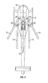
- FIG. 2 is a schematic view of a single rotor blade
- FIG. 3 is a plan view of a rotor for an aircraft in a folded condition
- FIG. 4 is a flow diagram of an embodiment of a blade fold system
- FIG. 5 is a flow diagram of another embodiment of a blade fold system.
- FIG. 1 Shown in FIG. 1 is a view of a rotor 10, for example, a helicopter.
- the rotor 10 includes a plurality of rotor blades 12 extending from a rotor hub 14.
- Each blade 12 includes features that allow for folding and unfolding of the blade 12.
- the blades 12 include a pitch lock 16 located at the hub 14.
- the pitch lock 16 is connected to a pitch lock actuator 18.
- the blades 12 each include and at least one hinge 20 and hinge lock 22 located along the blade 12 at a desired location.
- the hinge lock 22 is connected to a hinge lock actuator 26.
- a majority length of the airfoil of blade 12 is folded about the hinge 20 by a fold actuator 24.
- the actuators provide the forces necessary to move the all of the various components and when operated in the proper sequence allow the blades 12 to fold into a stowed position as shown in FIG. 3 .
- the system described herein is a hydraulic system including hydraulic pitch lock actuators 18 and hinge lock actuators 26, as well as hydraulic control of the hinge 20. It is to be appreciated, however, that the system may utilize other types of actuators, for example, electric actuators, to control the blade 12 fold and may require additional positioning actuators which move the blades 12 in other planes of motion about or around the hub 14.
- the pitch lock actuators 18, hinge lock actuators 26, and fold actuators 24 are connected to a fold control system 28 which controls the sequencing on the actuators 18, 26 and the fold actuator 24 during a blade fold and blade spread operation.
- Sensors 30 are located at each of the actuators 18, 26 and the fold actuators 24 to monitor the blade fold operation and are in operable communication with the fold control system 28. If, during operation of the blade fold system, a sensor 30 indicates an actuator 18, 26 and/or 24 is operating outside of a predetermined limit, the fold control system 28 takes appropriate action, which may include holding or aborting the blade fold operation or reversing the sequence to return to the starting configuration.
- FIG. 4 illustrates an example of a blade fold process including a method of fault detection in and control during the blade fold process.
- the pitch lock actuators 18 are activated in block 40.
- this may comprise opening a valve to allow hydraulic fluid to the pitch locks 16.
- a sensor 30 is disposed at each pitch lock 16 to determine if the pitch locks 16 are engaged (block 42), how far along their stroke the pitch locks 16 have advanced, and/or at what rate the pitch locks 16 are advancing to lock the pitch of the blades 12. If the sensors indicate that the pitch locks 16 do not begin to engage, or are not fully engaged within predetermined time limits (block 44), the fold control system 28 may stop all operation of the blade fold system (block 46).
- the fold control system 28 energizes the hinge lock actuators 26 to retract the hinge locks 22 thereby allowing the blades 12 to be folded (block 48).
- the sensors 30 disposed at the hinge locks 22 monitor the hinge lock 22 retraction to determine that the hinge lock 22 retraction is begun within a predetermined time limit 54 and that all of the hinge locks 22 are moving at the correct rate and also retracted within a time limit (block 52). If one of these conditions is not met, the fold control system 28 may take action including slowing or stopping the fold process (block 54).
- the fold control system 28 activates the fold actuator 24 at each hinge 20 to begin fold of the blades 12 in a desired sequence (block 56).
- the sensors 30 disposed at the hinges 20 monitor progress and rate (block 58) of the folding of each blade 12, especially relative to adjacent blades 12 to prevent collision of adjacent blades 12 during the fold operation. If the progress of folding an adjacent blade 12 is determined to be slower than desired when compared to a predetermined limit and or the progress of the blade 12, the fold control system 28 may slow or stop the fold operation (block 60).
- the folding of a particular blade 12 may begin immediately following retraction of the hinge lock 22 of the blade 12, not necessarily requiring retraction of all of the hinge locks 22 at all of the blades 12.
- the sensors 30 monitor progress of retraction of the hinge locks 22 and/or advancement of the hinges 20 of adjacent blades 12 to determine if the adjacent blades 12 are retracting at the desired rate. If the sensors indicate advancement is delayed or stopped unexpectedly, the fold control system 28 may slow or stop the fold operation.
- the folding operation is stopped by the fold control system 28 (block 64).
- Utilization of the sensors 30 and the fold control system 28 to monitor and control the fold operation increases the efficiency of the fold operation and increases prevention of collisions of blades 12 during the fold operation due to system faults by early detection of potential faults and immediate, automatic preventative action by the fold control system 28 such as stoppage of the fold operation prior to occurrence of the collision.
- Use of sensors 30 for monitoring reduces reliance on visual monitoring of the fold process, thereby reducing the potential for human error.
- Sensors 30 may also be utilized to monitor a blade spread process in which the blades 12 spread from the folded position shown in FIG. 3 to the spread position illustrated in FIG. 1 , thus forming a rotary wing.
- a blade spread process is illustrated in FIG. 5 .
- the sensors 30 confirm that the hinge locks 22 are fully retracted so the blade spread may begin without the blades 12 colliding with the hinge lock 22 mechanism.
- the fold control system 28 activates the fold actuator 24 at each hinge 20 to begin spread of the blades 12 in a desired sequence (block 68).
- the sensors 30 disposed at the hinges 20 monitor progress and rate (block 70) of the spread of each blade 12, especially relative to adjacent blades 12 to prevent collision of adjacent blades 12 during the fold operation. If the progress of spreading an adjacent blade 12 is determined to be slower than desired when compared to a predetermined limit and or the progress of the blade 12, the fold control system 28 may slow or stop the fold operation (block 72).
- the hinge locks 22 are engaged and engagement is confirmed by the sensors (block 74).
- the pitch locks 16 are retracted (block 76) via the pitch lock actuators 18.
- the sensors 30 at the pitch locks 16 monitor the pitch lock 16 disengagement, and when disengagement is confirmed by the sensors 30, the blade spread is complete (block 78).
Landscapes
- Engineering & Computer Science (AREA)
- Mechanical Engineering (AREA)
- Aviation & Aerospace Engineering (AREA)
- Transmission Devices (AREA)
- Testing Of Devices, Machine Parts, Or Other Structures Thereof (AREA)
- Wind Motors (AREA)
Abstract
Description
- This invention was made with Government support under N00019-06-C-0081 awarded by the Department of the Navy. The Government has certain rights in this invention.
- This application is a nonprovisional application of
U.S. Provisional Patent Application No. 61/355,345 filed June 16, 2010 - The subject matter disclosed herein relates to blade fold systems for aircraft.
- Rotor-driven aircraft, for example, helicopters, utilize blade folding systems which fold the blades of a main rotor to reduce the space required for parking and/or storing the aircraft. Such systems are typically activated by an operator and visually monitored. Upon activation, each blade is to individually articulate from a spread position to a folded position. In a blade fold or blade spread, a number of events must happen in the proper sequence, for each blade and also among the blades. During operation, however, any number of faults in the system may prevent the blade folding sequence from occurring as required, and thus operates in an undesired sequence. At such times, it is desired to stop the blade folding sequence before a collision between the blades occurs to prevent costly damage to the blades. Detecting these faults, however, requires human observation and is therefore prone to human error and inattention, and further may be acting at a speed not easily perceptible by humans (either too fast or too slow).
- According to one aspect of the invention, a rotor blade fold system for an aircraft includes one or more actuators operably connected to one or more blade components of one or more rotor blades of the aircraft. One or more sensors are located at the one or more rotor blades and are configured to sense operation of the one or more blade components. A fold control system is configured to monitor output from the one or more sensors and is capable of stopping operation of the blade fold system, via communication with the one or more actuators, if the one or more blade components are not operating within predetermined limits.
- According to another aspect of the invention, a method of folding one or more rotor blades of an aircraft includes activating one or more actuators operably connected to the one or more rotor blades. The one or more blades are urged toward a folded position via activation of the one or more actuators, and one or more blade components of the one or more rotor blades are monitored via one or more sensors disposed at the one or more rotor blades. A determination is made if the one or more blade components are operating within a predetermined limit, and operation of the blade fold system is stopped if the one or more blade components are not operating within the predetermined limit.
- These and other advantages and features will become more apparent from the following description taken in conjunction with the drawings.
Further embodiments of the invention are set out in the following numbered paragraphs: - 1. A rotor blade fold system for an aircraft comprising:
- one or more actuators operably connected to one or more blade components of one or more rotor blades of the aircraft; one or more sensors disposed at the one or more rotor blades configured to sense operation of the one or more blade components; and a fold control system which is configured to monitor
- output from the one or more sensors and capable of stopping operation of the blade fold system, via communication with the one or more actuators, if the one or more blade components are not operating within predetermined limits.
- 2. The blade fold system of paragraph 1, wherein the one or more blade components include a pitch lock, a hinge lock, a fold hinge and a fold actuator.
- 3. The blade fold system of paragraph 2, wherein a first sensor of one or more sensors is disposed at the pitch lock.4. The blade fold system of paragraph 3, wherein the first sensor is configured to determine if the pitch lock is engaged and/or position of the actuator along its stroke.
- 5. The blade fold system of paragraph 3, wherein the fold control system compares an engagement time for the pitch lock to engage to a predetermined limit, and is capable of stopping operation of the blade fold system if the engagement time exceeds the predetermined limit.
- 6. The blade fold system of paragraph 2, wherein a second sensor of the one or more sensors is disposed at the hinge lock.
- 7. The blade fold system of paragraph 6, wherein the second sensor is configured to determine if the hinge lock is released.
- 8. The blade fold system of paragraph 6, wherein the fold control system compares a release time for the hinge lock to release to a predetermined limit, and is capable of stopping operation of the blade fold system if the release time exceeds the predetermined limit.
- 9. The blade fold system of paragraph 2, wherein a third sensor of one or more sensors is disposed at the hinge.
- 10. The blade fold system of paragraph 9, wherein the third sensor is configured to determine a rate of movement of the rotor blade at the hinge.
- 11. The blade fold system of paragraph 9, wherein the fold control system compares a rate of movement of the rotor blade at the hinge to a predetermined limit, and is capable of stopping operation of the blade fold system if the rate of movement exceeds the predetermined limit.
- 12. An aircraft comprising: a rotor including: a rotor hub; and a plurality of rotor blades extending from the rotor hub; and a rotor blade fold system as recited in paragraph 1.
- 13. A method of folding one or more rotor blades of an aircraft comprising: activating one or more actuators operably connected to the one or more rotor blades; urging the one or more blades toward a folded position via activation of the one or more actuators; monitoring one or more blade components of the one or more rotor blades via one or more sensors disposed at the one or more rotor blades; determining if the one or more blade components are operating within a predetermined limit; and stopping operation of the blade fold system if the one or more blade components are not operating within the predetermined limit.
- 14. The method of paragraph 13, wherein the one or more blade components include a pitch lock, a hinge lock, and/or a hinge.
- 15. The method of
paragraph 14, further comprising monitoring the pitch lock via a first sensor of one or more sensors. - 16. The method of paragraph 15, further comprising: comparing an engagement time for the pitch lock to engage to a predetermined limit; and stopping operation of the blade fold system if the engagement time exceeds the predetermined limit.
- 17. The method of
paragraph 14, further comprising monitoring the hinge lock via a second sensor of the one or more sensors. - 18. The method of paragraph 17, further comprising: comparing a release time for the hinge lock to release to a predetermined limit; and stopping operation of the blade fold system if the release time exceeds the predetermined limit.
- 19. The method of
paragraph 14, further comprising monitoring the hinge via a third sensor of the one or more sensors. - 20. The method of paragraph 19, further comprising: comparing a rate of movement of the rotor blade at the hinge to a predetermined limit; and stopping operation of the blade fold system if the rate of movement exceeds the predetermined limit.
- The subject matter, which is regarded as the invention, is particularly pointed out and distinctly claimed in the claims at the conclusion of the specification. The foregoing and other features, and advantages of the invention are apparent from the following detailed description taken in conjunction with the accompanying drawings in which:
-
FIG. 1 is a plan view of a rotor for an aircraft in an extended configuration; -
FIG. 2 is a schematic view of a single rotor blade; -
FIG. 3 is a plan view of a rotor for an aircraft in a folded condition; -
FIG. 4 is a flow diagram of an embodiment of a blade fold system; and -
FIG. 5 is a flow diagram of another embodiment of a blade fold system. - The detailed description explains embodiments of the invention, together with advantages and features, by way of example with reference to the drawings.
- Shown in
FIG. 1 is a view of arotor 10, for example, a helicopter. Therotor 10 includes a plurality ofrotor blades 12 extending from arotor hub 14. Eachblade 12 includes features that allow for folding and unfolding of theblade 12. For example, as shown inFIG. 2 , theblades 12 include apitch lock 16 located at thehub 14. Thepitch lock 16 is connected to apitch lock actuator 18. Further, theblades 12 each include and at least onehinge 20 and hingelock 22 located along theblade 12 at a desired location. Thehinge lock 22 is connected to ahinge lock actuator 26. A majority length of the airfoil ofblade 12 is folded about thehinge 20 by afold actuator 24. The actuators provide the forces necessary to move the all of the various components and when operated in the proper sequence allow theblades 12 to fold into a stowed position as shown inFIG. 3 . The system described herein is a hydraulic system including hydraulicpitch lock actuators 18 and hingelock actuators 26, as well as hydraulic control of thehinge 20. It is to be appreciated, however, that the system may utilize other types of actuators, for example, electric actuators, to control theblade 12 fold and may require additional positioning actuators which move theblades 12 in other planes of motion about or around thehub 14. - Referring again to
FIG. 2 , thepitch lock actuators 18,hinge lock actuators 26, and foldactuators 24 are connected to afold control system 28 which controls the sequencing on theactuators fold actuator 24 during a blade fold and blade spread operation.Sensors 30 are located at each of theactuators fold actuators 24 to monitor the blade fold operation and are in operable communication with thefold control system 28. If, during operation of the blade fold system, asensor 30 indicates anactuator fold control system 28 takes appropriate action, which may include holding or aborting the blade fold operation or reversing the sequence to return to the starting configuration. -
FIG. 4 illustrates an example of a blade fold process including a method of fault detection in and control during the blade fold process. Thepitch lock actuators 18 are activated inblock 40. For example, in a hydraulic system, this may comprise opening a valve to allow hydraulic fluid to the pitch locks 16. Asensor 30 is disposed at eachpitch lock 16 to determine if the pitch locks 16 are engaged (block 42), how far along their stroke the pitch locks 16 have advanced, and/or at what rate the pitch locks 16 are advancing to lock the pitch of theblades 12. If the sensors indicate that the pitch locks 16 do not begin to engage, or are not fully engaged within predetermined time limits (block 44), thefold control system 28 may stop all operation of the blade fold system (block 46). - Once the pitch locks 16 are successfully engaged as indicated by the
sensors 30, thefold control system 28 energizes the hinge lock actuators 26 to retract the hinge locks 22 thereby allowing theblades 12 to be folded (block 48). Thesensors 30 disposed at the hinge locks 22 monitor thehinge lock 22 retraction to determine that thehinge lock 22 retraction is begun within apredetermined time limit 54 and that all of the hinge locks 22 are moving at the correct rate and also retracted within a time limit (block 52). If one of these conditions is not met, thefold control system 28 may take action including slowing or stopping the fold process (block 54). In some embodiments, once all of the hinge locks 22 are fully retracted, thefold control system 28 activates thefold actuator 24 at eachhinge 20 to begin fold of theblades 12 in a desired sequence (block 56). Thesensors 30 disposed at thehinges 20 monitor progress and rate (block 58) of the folding of eachblade 12, especially relative toadjacent blades 12 to prevent collision ofadjacent blades 12 during the fold operation. If the progress of folding anadjacent blade 12 is determined to be slower than desired when compared to a predetermined limit and or the progress of theblade 12, thefold control system 28 may slow or stop the fold operation (block 60). - In some embodiments, the folding of a
particular blade 12 may begin immediately following retraction of thehinge lock 22 of theblade 12, not necessarily requiring retraction of all of the hinge locks 22 at all of theblades 12. In such embodiments, thesensors 30 monitor progress of retraction of the hinge locks 22 and/or advancement of thehinges 20 ofadjacent blades 12 to determine if theadjacent blades 12 are retracting at the desired rate. If the sensors indicate advancement is delayed or stopped unexpectedly, thefold control system 28 may slow or stop the fold operation. - Once the
sensors 30 indicate that allblades 12 are fully folded (block 62), the folding operation is stopped by the fold control system 28 (block 64). Utilization of thesensors 30 and thefold control system 28 to monitor and control the fold operation increases the efficiency of the fold operation and increases prevention of collisions ofblades 12 during the fold operation due to system faults by early detection of potential faults and immediate, automatic preventative action by thefold control system 28 such as stoppage of the fold operation prior to occurrence of the collision. Use ofsensors 30 for monitoring reduces reliance on visual monitoring of the fold process, thereby reducing the potential for human error. -
Sensors 30 may also be utilized to monitor a blade spread process in which theblades 12 spread from the folded position shown inFIG. 3 to the spread position illustrated inFIG. 1 , thus forming a rotary wing. A blade spread process is illustrated inFIG. 5 . Inblock 66, thesensors 30 confirm that the hinge locks 22 are fully retracted so the blade spread may begin without theblades 12 colliding with thehinge lock 22 mechanism. Once retraction of the hinge locks 22 is confirmed, thefold control system 28 activates thefold actuator 24 at eachhinge 20 to begin spread of theblades 12 in a desired sequence (block 68). Thesensors 30 disposed at thehinges 20 monitor progress and rate (block 70) of the spread of eachblade 12, especially relative toadjacent blades 12 to prevent collision ofadjacent blades 12 during the fold operation. If the progress of spreading anadjacent blade 12 is determined to be slower than desired when compared to a predetermined limit and or the progress of theblade 12, thefold control system 28 may slow or stop the fold operation (block 72). - When the
blades 12 reach their fully spread position, as shown for example, inFIG. 1 , the hinge locks 22 are engaged and engagement is confirmed by the sensors (block 74). The pitch locks 16 are retracted (block 76) via thepitch lock actuators 18. Thesensors 30 at the pitch locks 16 monitor thepitch lock 16 disengagement, and when disengagement is confirmed by thesensors 30, the blade spread is complete (block 78). - While the invention has been described in detail in connection with only a limited number of embodiments, it should be readily understood that the invention is not limited to such disclosed embodiments. Rather, the invention can be modified to incorporate any number of variations, alterations, substitutions or equivalent arrangements not heretofore described, but which are commensurate with the spirit and scope of the invention. Additionally, while various embodiments of the invention have been described, it is to be understood that aspects of the invention may include only some of the described embodiments. Accordingly, the invention is not to be seen as limited by the foregoing description, but is only limited by the scope of the appended claims.
Claims (15)
- A rotor blade fold system for an aircraft comprising:one or more actuators operably connected to one or more blade components of one or more rotor blades of the aircraft;one or more sensors disposed at the one or more rotor blades configured to sense operation of the one or more blade components; anda fold control system which is configured to monitor output from the one or more sensors and capable of stopping operation of the blade fold system, via communication with the one or more actuators, if the one or more blade components are not operating within predetermined limits.
- The blade fold system of Claim 1, wherein the one or more blade components include a pitch lock, a hinge lock, a fold hinge and a fold actuator.
- The blade fold system of Claim 1 or 2, wherein a first sensor of one or more sensors is disposed at the pitch lock.
- The blade fold system of any of the preceding claims, wherein the first sensor is configured to determine if the pitch lock is engaged and/or position of the actuator along its stroke.
- The blade fold system of Claim 3 or 4, wherein the fold control system compares an engagement time for the pitch lock to engage to a predetermined limit, and is capable of stopping operation of the blade fold system if the engagement time exceeds the predetermined limit.
- The blade fold system of any of Claim 2 to 5, wherein a second sensor of the one or more sensors is disposed at the hinge lock.
- The blade fold system of Claim 6, wherein the second sensor is configured to determine if the hinge lock is released.
- The blade fold system of Claim 6 or 7, wherein the fold control system compares a release time for the hinge lock to release to a predetermined limit, and is capable of stopping operation of the blade fold system if the release time exceeds the predetermined limit.
- The blade fold system of any of Claims 2 to 8, wherein a third sensor of one or more sensors is disposed at the hinge.
- The blade fold system of Claim 9, wherein the third sensor is configured to determine a rate of movement of the rotor blade at the hinge.
- The blade fold system of Claim 9 or 10, wherein the fold control system compares a rate of movement of the rotor blade at the hinge to a predetermined limit, and is capable of stopping operation of the blade fold system if the rate of movement exceeds the predetermined limit.
- A method of folding one or more rotor blades of an aircraft comprising:activating one or more actuators operably connected to the one or more rotor blades;urging the one or more blades toward a folded position via activation of the one or more actuators;monitoring one or more blade components of the one or more rotor blades via one or more sensors disposed at the one or more rotor blades;determining if the one or more blade components are operating within a predetermined limit; andstopping operation of the blade fold system if the one or more blade components are not operating within the predetermined limit.
- The method of Claim 12, wherein the one or more blade components include a pitch lock, a hinge lock, and/or a hinge.
- The method of Claim 13, further comprising monitoring the pitch lock via a first sensor of one or more sensors.
- The method of Claim 14, further comprising:comparing an engagement time for the pitch lock to engage to a predetermined limit; andstopping operation of the blade fold system if the engagement time exceeds the predetermined limit.
Applications Claiming Priority (1)
| Application Number | Priority Date | Filing Date | Title |
|---|---|---|---|
| US35534510P | 2010-06-16 | 2010-06-16 |
Publications (3)
| Publication Number | Publication Date |
|---|---|
| EP2397408A2 true EP2397408A2 (en) | 2011-12-21 |
| EP2397408A3 EP2397408A3 (en) | 2013-12-11 |
| EP2397408B1 EP2397408B1 (en) | 2017-07-05 |
Family
ID=44478633
Family Applications (1)
| Application Number | Title | Priority Date | Filing Date |
|---|---|---|---|
| EP11162704.8A Not-in-force EP2397408B1 (en) | 2010-06-16 | 2011-04-15 | Blade fold system monitoring |
Country Status (2)
| Country | Link |
|---|---|
| US (1) | US9108727B2 (en) |
| EP (1) | EP2397408B1 (en) |
Cited By (3)
| Publication number | Priority date | Publication date | Assignee | Title |
|---|---|---|---|---|
| WO2016118230A1 (en) * | 2015-01-21 | 2016-07-28 | Sikorsky Aircraft Corporation | Flying wing vertical take-off and landing aircraft |
| EP3357812A1 (en) * | 2017-02-03 | 2018-08-08 | Bell Helicopter Textron Inc. | Variable in-flight wing fold system |
| CN112173098A (en) * | 2020-09-25 | 2021-01-05 | 中国直升机设计研究所 | Novel control system and method for electric folding and unfolding of rotor wing |
Families Citing this family (7)
| Publication number | Priority date | Publication date | Assignee | Title |
|---|---|---|---|---|
| CN112722300A (en) | 2015-04-21 | 2021-04-30 | 高途乐公司 | Aerial capture platform |
| US12221237B2 (en) | 2015-04-21 | 2025-02-11 | Gopro, Inc. | Unmanned aerial vehicle with rotating and overlapping rotor arms |
| US10696414B2 (en) | 2015-04-21 | 2020-06-30 | Gopro, Inc. | Aerial capture platform |
| EP4660079A3 (en) * | 2017-05-22 | 2026-01-14 | Archer Aviation Inc. | Evtol aircraft using large, variable speed tilt rotors |
| US11174017B2 (en) * | 2019-05-30 | 2021-11-16 | Lockheed Martin Corporation | Rotor blade folding system |
| KR20220168902A (en) * | 2021-06-17 | 2022-12-26 | 현대자동차주식회사 | Propeller control system of air mobility |
| DE102021005865B4 (en) | 2021-11-26 | 2025-07-17 | Bundesrepublik Deutschland (Bundesamt für Ausrüstung, Informationstechnik und Nutzung der Bundeswehr) | Device and method for folding and spreading rotor blade pivot joints |
Family Cites Families (16)
| Publication number | Priority date | Publication date | Assignee | Title |
|---|---|---|---|---|
| US3101785A (en) | 1961-06-28 | 1963-08-27 | United Aircraft Corp | Blade folding device |
| US3802798A (en) | 1973-01-30 | 1974-04-09 | Us Air Force | Rotor blade capturing assembly |
| US4028001A (en) | 1975-07-28 | 1977-06-07 | Westland Aircraft Limited | Rotor for rotary wing aircraft |
| US4284387A (en) | 1979-05-02 | 1981-08-18 | United Technologies Corp. | Blade fold restraint system |
| US4376979A (en) * | 1980-10-10 | 1983-03-15 | United Technologies Corporation | Updated lock-positioning of foldable helicopter blades |
| EP0057053A1 (en) | 1981-01-22 | 1982-08-04 | WESTLAND plc | Helicopter rotors |
| US5031858A (en) * | 1989-11-20 | 1991-07-16 | Bell Helicopter Textron, Inc. | Apparatus and method for folding and locking rotor blades |
| FR2742726B1 (en) | 1995-12-22 | 1998-02-20 | Eurocopter France | DEVICE FOR FOLDING A BLADE OF A GIRAVION ROTOR |
| FR2754779B1 (en) | 1996-10-22 | 1998-12-31 | Eurocopter France | METHOD FOR FOLDING THE BLADES OF A MAIN ROTOR OF A GIRAVION AND DEVICE FOR IMPLEMENTING SAME |
| US6213712B1 (en) | 1999-12-03 | 2001-04-10 | Mcdonnell Douglas Corporation | Helicopter blade positioning mechanism for foldable rotor blades |
| FR2836889B1 (en) | 2002-03-11 | 2004-05-28 | Eurocopter France | METHOD AND DEVICE FOR FOLDING-FOLDING THE BLADES OF A ROTOR OF A GIRAVION |
| US6783327B1 (en) * | 2002-12-12 | 2004-08-31 | Davis Aircraft Products Co., Inc. | Helicopter blade folding with blade droop |
| US20060067822A1 (en) | 2004-09-24 | 2006-03-30 | D Anna Frank P | Pitch lock and lag positioner for a rotor blade folding system |
| US20060120873A1 (en) * | 2004-12-03 | 2006-06-08 | Sikorsky Aircraft Corporation | Damper positioner for a rotor blade folding system |
| US7798442B2 (en) | 2006-03-17 | 2010-09-21 | Sikorsky Aircraft Corporation | Rotor assemblies having automatic blade folding systems |
| US7530790B2 (en) | 2006-09-20 | 2009-05-12 | Sikorsky Aircraft Corporation | Rotor blade folding system |
-
2011
- 2011-04-13 US US13/086,003 patent/US9108727B2/en not_active Expired - Fee Related
- 2011-04-15 EP EP11162704.8A patent/EP2397408B1/en not_active Not-in-force
Cited By (5)
| Publication number | Priority date | Publication date | Assignee | Title |
|---|---|---|---|---|
| WO2016118230A1 (en) * | 2015-01-21 | 2016-07-28 | Sikorsky Aircraft Corporation | Flying wing vertical take-off and landing aircraft |
| US10723453B2 (en) | 2015-01-21 | 2020-07-28 | Sikorsky Aircraft Corporation | Flying wing vertical take-off and landing aircraft |
| EP3357812A1 (en) * | 2017-02-03 | 2018-08-08 | Bell Helicopter Textron Inc. | Variable in-flight wing fold system |
| US10407160B2 (en) | 2017-02-03 | 2019-09-10 | Bell Helicopter Textron Inc. | Variable in-flight wing fold system |
| CN112173098A (en) * | 2020-09-25 | 2021-01-05 | 中国直升机设计研究所 | Novel control system and method for electric folding and unfolding of rotor wing |
Also Published As
| Publication number | Publication date |
|---|---|
| US9108727B2 (en) | 2015-08-18 |
| US20120121412A1 (en) | 2012-05-17 |
| EP2397408A3 (en) | 2013-12-11 |
| EP2397408B1 (en) | 2017-07-05 |
Similar Documents
| Publication | Publication Date | Title |
|---|---|---|
| US9108727B2 (en) | Blade fold system monitoring | |
| US8123161B1 (en) | Aircraft landing gear unlock actuator | |
| US8827205B2 (en) | Pneumatic blow-down actuator | |
| US8868261B2 (en) | Monitoring device for an actuation system of an aircraft, actuation system and method for reconfiguring the actuation system | |
| US8702035B2 (en) | Actuation apparatus for use on an aircraft | |
| US9771144B2 (en) | High lift system for an aircraft, aircraft having a wing and a high lift system and method for moving a high lift surface relative to the wing of an aircraft | |
| EP3208189B1 (en) | Aerodynamic control surface movement monitoring system | |
| EP3239043B1 (en) | System and method for controlling aircraft wing flap motion | |
| EP3284679B1 (en) | Inflight stow of ram air turbine | |
| EP2905467A1 (en) | Wind-powered electricity generation device and method for locking rotation of rotor head of same | |
| CN103072687A (en) | Landing gear, an aircraft, and a method implemented by landing gear | |
| CN104071330A (en) | Monitoring of high-lift systems for aircraft | |
| CN111372852B (en) | System and method for actuating a high lift flight control surface | |
| EP2865851A1 (en) | Rotary hydraulic motor driven hybrid thrust reverser actuation system with end-of-stroke snubbing | |
| CN105711814A (en) | Method for determining state of component in high lift system of aircraft | |
| EP3549859B1 (en) | Hydraulic power drive unit | |
| EP3176073A1 (en) | A dual-purpose locking and folding arrangement for an aircraft wing tip device | |
| US9458795B2 (en) | Actuation device for moving a movable cover of a thrust reverser | |
| EP3737849B1 (en) | Thrust reverser and method of controlling hydraulic actuation | |
| EP2216619B1 (en) | Flight abort device for a missile | |
| US12534190B2 (en) | Drive system for a lift control device of an aircraft, aircraft wing and aircraft | |
| EP2535272B1 (en) | Boom control system | |
| CN119551180A (en) | Aircraft wing folding system and control method thereof |
Legal Events
| Date | Code | Title | Description |
|---|---|---|---|
| AK | Designated contracting states |
Kind code of ref document: A2 Designated state(s): AL AT BE BG CH CY CZ DE DK EE ES FI FR GB GR HR HU IE IS IT LI LT LU LV MC MK MT NL NO PL PT RO RS SE SI SK SM TR |
|
| AX | Request for extension of the european patent |
Extension state: BA ME |
|
| PUAI | Public reference made under article 153(3) epc to a published international application that has entered the european phase |
Free format text: ORIGINAL CODE: 0009012 |
|
| PUAL | Search report despatched |
Free format text: ORIGINAL CODE: 0009013 |
|
| AK | Designated contracting states |
Kind code of ref document: A3 Designated state(s): AL AT BE BG CH CY CZ DE DK EE ES FI FR GB GR HR HU IE IS IT LI LT LU LV MC MK MT NL NO PL PT RO RS SE SI SK SM TR |
|
| AX | Request for extension of the european patent |
Extension state: BA ME |
|
| RIC1 | Information provided on ipc code assigned before grant |
Ipc: B64C 27/50 20060101AFI20131107BHEP |
|
| 17P | Request for examination filed |
Effective date: 20140606 |
|
| RBV | Designated contracting states (corrected) |
Designated state(s): AL AT BE BG CH CY CZ DE DK EE ES FI FR GB GR HR HU IE IS IT LI LT LU LV MC MK MT NL NO PL PT RO RS SE SI SK SM TR |
|
| 17Q | First examination report despatched |
Effective date: 20160718 |
|
| GRAP | Despatch of communication of intention to grant a patent |
Free format text: ORIGINAL CODE: EPIDOSNIGR1 |
|
| INTG | Intention to grant announced |
Effective date: 20170118 |
|
| GRAS | Grant fee paid |
Free format text: ORIGINAL CODE: EPIDOSNIGR3 |
|
| GRAA | (expected) grant |
Free format text: ORIGINAL CODE: 0009210 |
|
| AK | Designated contracting states |
Kind code of ref document: B1 Designated state(s): AL AT BE BG CH CY CZ DE DK EE ES FI FR GB GR HR HU IE IS IT LI LT LU LV MC MK MT NL NO PL PT RO RS SE SI SK SM TR |
|
| REG | Reference to a national code |
Ref country code: GB Ref legal event code: FG4D |
|
| REG | Reference to a national code |
Ref country code: CH Ref legal event code: EP |
|
| REG | Reference to a national code |
Ref country code: AT Ref legal event code: REF Ref document number: 906396 Country of ref document: AT Kind code of ref document: T Effective date: 20170715 |
|
| REG | Reference to a national code |
Ref country code: IE Ref legal event code: FG4D |
|
| REG | Reference to a national code |
Ref country code: DE Ref legal event code: R096 Ref document number: 602011039253 Country of ref document: DE |
|
| REG | Reference to a national code |
Ref country code: NL Ref legal event code: MP Effective date: 20170705 |
|
| REG | Reference to a national code |
Ref country code: AT Ref legal event code: MK05 Ref document number: 906396 Country of ref document: AT Kind code of ref document: T Effective date: 20170705 |
|
| REG | Reference to a national code |
Ref country code: LT Ref legal event code: MG4D |
|
| PG25 | Lapsed in a contracting state [announced via postgrant information from national office to epo] |
Ref country code: NL Free format text: LAPSE BECAUSE OF FAILURE TO SUBMIT A TRANSLATION OF THE DESCRIPTION OR TO PAY THE FEE WITHIN THE PRESCRIBED TIME-LIMIT Effective date: 20170705 Ref country code: LT Free format text: LAPSE BECAUSE OF FAILURE TO SUBMIT A TRANSLATION OF THE DESCRIPTION OR TO PAY THE FEE WITHIN THE PRESCRIBED TIME-LIMIT Effective date: 20170705 Ref country code: FI Free format text: LAPSE BECAUSE OF FAILURE TO SUBMIT A TRANSLATION OF THE DESCRIPTION OR TO PAY THE FEE WITHIN THE PRESCRIBED TIME-LIMIT Effective date: 20170705 Ref country code: HR Free format text: LAPSE BECAUSE OF FAILURE TO SUBMIT A TRANSLATION OF THE DESCRIPTION OR TO PAY THE FEE WITHIN THE PRESCRIBED TIME-LIMIT Effective date: 20170705 Ref country code: SE Free format text: LAPSE BECAUSE OF FAILURE TO SUBMIT A TRANSLATION OF THE DESCRIPTION OR TO PAY THE FEE WITHIN THE PRESCRIBED TIME-LIMIT Effective date: 20170705 Ref country code: NO Free format text: LAPSE BECAUSE OF FAILURE TO SUBMIT A TRANSLATION OF THE DESCRIPTION OR TO PAY THE FEE WITHIN THE PRESCRIBED TIME-LIMIT Effective date: 20171005 Ref country code: AT Free format text: LAPSE BECAUSE OF FAILURE TO SUBMIT A TRANSLATION OF THE DESCRIPTION OR TO PAY THE FEE WITHIN THE PRESCRIBED TIME-LIMIT Effective date: 20170705 |
|
| PG25 | Lapsed in a contracting state [announced via postgrant information from national office to epo] |
Ref country code: RS Free format text: LAPSE BECAUSE OF FAILURE TO SUBMIT A TRANSLATION OF THE DESCRIPTION OR TO PAY THE FEE WITHIN THE PRESCRIBED TIME-LIMIT Effective date: 20170705 Ref country code: ES Free format text: LAPSE BECAUSE OF FAILURE TO SUBMIT A TRANSLATION OF THE DESCRIPTION OR TO PAY THE FEE WITHIN THE PRESCRIBED TIME-LIMIT Effective date: 20170705 Ref country code: IS Free format text: LAPSE BECAUSE OF FAILURE TO SUBMIT A TRANSLATION OF THE DESCRIPTION OR TO PAY THE FEE WITHIN THE PRESCRIBED TIME-LIMIT Effective date: 20171105 Ref country code: PL Free format text: LAPSE BECAUSE OF FAILURE TO SUBMIT A TRANSLATION OF THE DESCRIPTION OR TO PAY THE FEE WITHIN THE PRESCRIBED TIME-LIMIT Effective date: 20170705 Ref country code: BG Free format text: LAPSE BECAUSE OF FAILURE TO SUBMIT A TRANSLATION OF THE DESCRIPTION OR TO PAY THE FEE WITHIN THE PRESCRIBED TIME-LIMIT Effective date: 20171005 Ref country code: GR Free format text: LAPSE BECAUSE OF FAILURE TO SUBMIT A TRANSLATION OF THE DESCRIPTION OR TO PAY THE FEE WITHIN THE PRESCRIBED TIME-LIMIT Effective date: 20171006 Ref country code: LV Free format text: LAPSE BECAUSE OF FAILURE TO SUBMIT A TRANSLATION OF THE DESCRIPTION OR TO PAY THE FEE WITHIN THE PRESCRIBED TIME-LIMIT Effective date: 20170705 |
|
| REG | Reference to a national code |
Ref country code: DE Ref legal event code: R097 Ref document number: 602011039253 Country of ref document: DE |
|
| PG25 | Lapsed in a contracting state [announced via postgrant information from national office to epo] |
Ref country code: RO Free format text: LAPSE BECAUSE OF FAILURE TO SUBMIT A TRANSLATION OF THE DESCRIPTION OR TO PAY THE FEE WITHIN THE PRESCRIBED TIME-LIMIT Effective date: 20170705 Ref country code: DK Free format text: LAPSE BECAUSE OF FAILURE TO SUBMIT A TRANSLATION OF THE DESCRIPTION OR TO PAY THE FEE WITHIN THE PRESCRIBED TIME-LIMIT Effective date: 20170705 Ref country code: CZ Free format text: LAPSE BECAUSE OF FAILURE TO SUBMIT A TRANSLATION OF THE DESCRIPTION OR TO PAY THE FEE WITHIN THE PRESCRIBED TIME-LIMIT Effective date: 20170705 |
|
| PLBE | No opposition filed within time limit |
Free format text: ORIGINAL CODE: 0009261 |
|
| STAA | Information on the status of an ep patent application or granted ep patent |
Free format text: STATUS: NO OPPOSITION FILED WITHIN TIME LIMIT |
|
| PG25 | Lapsed in a contracting state [announced via postgrant information from national office to epo] |
Ref country code: EE Free format text: LAPSE BECAUSE OF FAILURE TO SUBMIT A TRANSLATION OF THE DESCRIPTION OR TO PAY THE FEE WITHIN THE PRESCRIBED TIME-LIMIT Effective date: 20170705 Ref country code: SM Free format text: LAPSE BECAUSE OF FAILURE TO SUBMIT A TRANSLATION OF THE DESCRIPTION OR TO PAY THE FEE WITHIN THE PRESCRIBED TIME-LIMIT Effective date: 20170705 Ref country code: SK Free format text: LAPSE BECAUSE OF FAILURE TO SUBMIT A TRANSLATION OF THE DESCRIPTION OR TO PAY THE FEE WITHIN THE PRESCRIBED TIME-LIMIT Effective date: 20170705 |
|
| 26N | No opposition filed |
Effective date: 20180406 |
|
| PG25 | Lapsed in a contracting state [announced via postgrant information from national office to epo] |
Ref country code: SI Free format text: LAPSE BECAUSE OF FAILURE TO SUBMIT A TRANSLATION OF THE DESCRIPTION OR TO PAY THE FEE WITHIN THE PRESCRIBED TIME-LIMIT Effective date: 20170705 |
|
| REG | Reference to a national code |
Ref country code: DE Ref legal event code: R119 Ref document number: 602011039253 Country of ref document: DE |
|
| PG25 | Lapsed in a contracting state [announced via postgrant information from national office to epo] |
Ref country code: MC Free format text: LAPSE BECAUSE OF FAILURE TO SUBMIT A TRANSLATION OF THE DESCRIPTION OR TO PAY THE FEE WITHIN THE PRESCRIBED TIME-LIMIT Effective date: 20170705 |
|
| REG | Reference to a national code |
Ref country code: CH Ref legal event code: PL |
|
| REG | Reference to a national code |
Ref country code: BE Ref legal event code: MM Effective date: 20180430 |
|
| GBPC | Gb: european patent ceased through non-payment of renewal fee |
Effective date: 20180415 |
|
| REG | Reference to a national code |
Ref country code: IE Ref legal event code: MM4A |
|
| PG25 | Lapsed in a contracting state [announced via postgrant information from national office to epo] |
Ref country code: DE Free format text: LAPSE BECAUSE OF NON-PAYMENT OF DUE FEES Effective date: 20181101 Ref country code: LU Free format text: LAPSE BECAUSE OF NON-PAYMENT OF DUE FEES Effective date: 20180415 |
|
| PG25 | Lapsed in a contracting state [announced via postgrant information from national office to epo] |
Ref country code: BE Free format text: LAPSE BECAUSE OF NON-PAYMENT OF DUE FEES Effective date: 20180430 Ref country code: LI Free format text: LAPSE BECAUSE OF NON-PAYMENT OF DUE FEES Effective date: 20180430 Ref country code: CH Free format text: LAPSE BECAUSE OF NON-PAYMENT OF DUE FEES Effective date: 20180430 Ref country code: GB Free format text: LAPSE BECAUSE OF NON-PAYMENT OF DUE FEES Effective date: 20180415 |
|
| PG25 | Lapsed in a contracting state [announced via postgrant information from national office to epo] |
Ref country code: IE Free format text: LAPSE BECAUSE OF NON-PAYMENT OF DUE FEES Effective date: 20180415 Ref country code: IT Free format text: LAPSE BECAUSE OF NON-PAYMENT OF DUE FEES Effective date: 20180415 Ref country code: FR Free format text: LAPSE BECAUSE OF NON-PAYMENT OF DUE FEES Effective date: 20180430 |
|
| PG25 | Lapsed in a contracting state [announced via postgrant information from national office to epo] |
Ref country code: MT Free format text: LAPSE BECAUSE OF NON-PAYMENT OF DUE FEES Effective date: 20180415 |
|
| PG25 | Lapsed in a contracting state [announced via postgrant information from national office to epo] |
Ref country code: TR Free format text: LAPSE BECAUSE OF FAILURE TO SUBMIT A TRANSLATION OF THE DESCRIPTION OR TO PAY THE FEE WITHIN THE PRESCRIBED TIME-LIMIT Effective date: 20170705 |
|
| PG25 | Lapsed in a contracting state [announced via postgrant information from national office to epo] |
Ref country code: HU Free format text: LAPSE BECAUSE OF FAILURE TO SUBMIT A TRANSLATION OF THE DESCRIPTION OR TO PAY THE FEE WITHIN THE PRESCRIBED TIME-LIMIT; INVALID AB INITIO Effective date: 20110415 Ref country code: PT Free format text: LAPSE BECAUSE OF FAILURE TO SUBMIT A TRANSLATION OF THE DESCRIPTION OR TO PAY THE FEE WITHIN THE PRESCRIBED TIME-LIMIT Effective date: 20170705 |
|
| PG25 | Lapsed in a contracting state [announced via postgrant information from national office to epo] |
Ref country code: CY Free format text: LAPSE BECAUSE OF FAILURE TO SUBMIT A TRANSLATION OF THE DESCRIPTION OR TO PAY THE FEE WITHIN THE PRESCRIBED TIME-LIMIT Effective date: 20170705 Ref country code: MK Free format text: LAPSE BECAUSE OF NON-PAYMENT OF DUE FEES Effective date: 20170705 |
|
| PG25 | Lapsed in a contracting state [announced via postgrant information from national office to epo] |
Ref country code: AL Free format text: LAPSE BECAUSE OF FAILURE TO SUBMIT A TRANSLATION OF THE DESCRIPTION OR TO PAY THE FEE WITHIN THE PRESCRIBED TIME-LIMIT Effective date: 20170705 |