EP2395380A1 - Scanning microscope - Google Patents
Scanning microscope Download PDFInfo
- Publication number
- EP2395380A1 EP2395380A1 EP11004598A EP11004598A EP2395380A1 EP 2395380 A1 EP2395380 A1 EP 2395380A1 EP 11004598 A EP11004598 A EP 11004598A EP 11004598 A EP11004598 A EP 11004598A EP 2395380 A1 EP2395380 A1 EP 2395380A1
- Authority
- EP
- European Patent Office
- Prior art keywords
- scanning microscope
- light
- mirror
- wavelength region
- photodetector
- Prior art date
- Legal status (The legal status is an assumption and is not a legal conclusion. Google has not performed a legal analysis and makes no representation as to the accuracy of the status listed.)
- Granted
Links
- 230000003287 optical effect Effects 0.000 claims description 41
- 238000001514 detection method Methods 0.000 description 50
- 238000010586 diagram Methods 0.000 description 12
- 238000012423 maintenance Methods 0.000 description 10
- 239000006185 dispersion Substances 0.000 description 9
- 230000000694 effects Effects 0.000 description 6
- 238000000034 method Methods 0.000 description 5
- 230000004907 flux Effects 0.000 description 4
- 239000013307 optical fiber Substances 0.000 description 3
- 230000010287 polarization Effects 0.000 description 3
- 239000003086 colorant Substances 0.000 description 2
- 230000007423 decrease Effects 0.000 description 2
- 238000002073 fluorescence micrograph Methods 0.000 description 2
- 239000000126 substance Substances 0.000 description 2
- 230000023077 detection of light stimulus Effects 0.000 description 1
- 230000009189 diving Effects 0.000 description 1
- 238000003780 insertion Methods 0.000 description 1
- 230000037431 insertion Effects 0.000 description 1
- 230000003595 spectral effect Effects 0.000 description 1
Images





Classifications
-
- G—PHYSICS
- G02—OPTICS
- G02B—OPTICAL ELEMENTS, SYSTEMS OR APPARATUS
- G02B21/00—Microscopes
- G02B21/0004—Microscopes specially adapted for specific applications
- G02B21/002—Scanning microscopes
- G02B21/0024—Confocal scanning microscopes (CSOMs) or confocal "macroscopes"; Accessories which are not restricted to use with CSOMs, e.g. sample holders
- G02B21/0052—Optical details of the image generation
- G02B21/0064—Optical details of the image generation multi-spectral or wavelength-selective arrangements, e.g. wavelength fan-out, chromatic profiling
-
- G—PHYSICS
- G02—OPTICS
- G02B—OPTICAL ELEMENTS, SYSTEMS OR APPARATUS
- G02B21/00—Microscopes
- G02B21/0004—Microscopes specially adapted for specific applications
- G02B21/002—Scanning microscopes
- G02B21/0024—Confocal scanning microscopes (CSOMs) or confocal "macroscopes"; Accessories which are not restricted to use with CSOMs, e.g. sample holders
- G02B21/0052—Optical details of the image generation
- G02B21/0076—Optical details of the image generation arrangements using fluorescence or luminescence
-
- G—PHYSICS
- G02—OPTICS
- G02B—OPTICAL ELEMENTS, SYSTEMS OR APPARATUS
- G02B5/00—Optical elements other than lenses
- G02B5/32—Holograms used as optical elements
Definitions
- the present invention relates to a scanning microscope and particularly relates to a scanning microscope that has a spectroscopic detection function.
- confocal scanning microscopes provided with a spectroscopic detection function are used for fluorescence observations; however, as a general rule, fluorescence is weak so that the light quantity of the fluorescence obtained per unit time is small. Since a sample observed under a confocal scanning microscope is scanned at a high speed, only a short period of time is spent on exciting each point on the sample. Therefore, in order to obtain a bright image, it is necessary to efficiently lead a limited amount of generated fluorescence to a photodetector.
- a reflective diffraction grating is generally a surface-relief diffraction grating which has the relief structure on the surface so as to obtain diffracted light and the diffraction efficiency of the surface-relief diffraction grating is on the order of 70% at most.
- Spectroscopic means is generally an optical element that loses a large quantity of light; accordingly, in a confocal scanning microscope provided with a spectroscopic detection function, suppressing the light loss caused at spectroscopic means is effective to improve light-use efficiency.
- a technology for suppressing light loss caused at spectroscopic means is disclosed in, for example, Japanese Laid-open Patent Publication No. 2006-153587 .
- Japanese Laid-open Patent Publication No. 2006-153587 by focusing attention on the characteristic depending on polarization direction of a reflective diffraction grating that is spectroscopic means, a technology is disclosed in which incident light is converted into S polarized light indicating higher diffraction efficiency so as to suppress light loss caused at the spectroscopic means.
- Use of the technology disclosed in Japanese Laid-open Patent Publication No. 2006-153587 can improve the light-use efficiency of a confocal scanning microscope provided with a spectroscopic detection function.
- incident light is divided into P polarized light and S polarized light, which are led through different light paths to a reflective diffraction grating.
- a polarization beam splitter for diving incident light into P polarized light and S polarized light is used, and light loss will occur at the polarization beam splitter.
- a wavelength plate for rotating polarized light is used in order to convert P polarized light into S polarized light, and light loss will also occur at the wavelength plate.
- an object of the present invention is to provide a confocal microscope that is provided with a spectroscopic detection function and that has high light-use efficiency for a wide wavelength region.
- a first aspect of the present invention provides a scanning microscope provided with a scan unit that scans a sample, the scanning microscope including: a transmissive VPH grating for dispersing light from the sample; and a photodetector for detecting the light diffracted by the VPH grating.
- VPH grating 1 included in the confocal scanning microscope will be described with reference to Figs. 1A, 1B, 1C , and 2 .
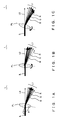
- Figs. 1A-1C are each a diagram illustrating actions of a Volume Phase Holographic grating (hereinafter referred to as a VPH grating) included in the confocal scanning microscope according to the present embodiment.
- Fig. 2 is a diagram illustrating diffraction characteristics of the VPH grating illustrated in Figs. 1A-1C .
- the ordinate and the abscissa indicate a diffraction efficiency (DE) (%) and a wavelength (nm), respectively.
- Characteristic Cr illustrated in Fig. 2 indicates a diffraction characteristic of a surface-relief diffraction grating according to a prior art.
- Characteristics Ca, Cb, and Cc in Fig. 2 indicate diffraction characteristics of the VPH grating 1 according to the present embodiment illustrated in Figs. 1A, 1B and 1C , respectively.
- the VPH grating 1 illustrated in Figs. 1A-1C includes a VPH layer whose refractive index cyclically changes along a main straight-line PL.
- the direction parallel to the main straight-line PL along which the refractive index cyclically changes will be hereinafter referred to as a refractive-index distribution direction.
- the VPH grating 1 is a transmissive diffraction grating that emits 0-th order diffracted light L0 in the direction parallel to incident light IL and emits, for each wavelength, first order diffracted light L1 forming a different angle with the 0-th order diffracted light.
- the VPH grating 1 has a diffraction characteristic that can achieve high diffraction efficiency for a wide band in comparison with a surface-relief diffraction grating.
- VPH gratings have a tradeoff between the maximum diffraction efficiency and a bandwidth in which diffracted light can be obtained. Accordingly, the diffraction characteristic achieved by VPH gratings has selectivity.
- the VPH grating 1 according to the present embodiment is a VPH grating designed so that it achieves a diffraction characteristic achieving a higher diffraction efficiency than a surface-relief diffraction grating (see characteristic Cr in Fig. 2 ) and achieving a bandwidth as wide as or wider than the surface-relief diffraction grating (see characteristic Cr in Fig. 2 ).
- the diffraction characteristic of the VPH grating 1 has the following features.
- the wavelength at the peak of the diffraction efficiency of the first order diffracted light L1 (hereinafter referred to as a first order diffraction efficiency) (this wavelength will be hereinafter referred to as a Bragg wavelength) changes.
- the Bragg wavelength changes depending on an incident angle ⁇ 2, the Bragg wavelength changes.
- the first order diffraction efficiency for the wavelength G (green) is the highest (See characteristic Ca in Fig. 2 .
- a broader arrow indicates a higher diffraction efficiency in Fig. 1A ).
- the peak of the diffraction efficiency is shifted to the short wavelength side so that the first order diffraction efficiency for the wavelength B (blue) becomes the highest (see characteristic Cb in Fig. 2 ).
- the angle formed by the incident light IL and the first order diffracted light remains almost the same under the condition of the same wavelength. Accordingly, the angle formed by the 0-th order diffracted light L0 and the first order diffracted light (hereinafter referred to as an exit angle) also remains almost the same under the condition of the same wavelength. In other words, if the direction of the 0-th order diffracted light L0 is fixed, the emission direction (hereinafter referred to as a diffraction direction) of the first order diffracted light is essentially fixed under the condition of the same wavelength.
- Figs. 3A and 3B are each a diagram illustrating a diffraction provided by a transmissive diffraction grating including the VPH grating 1.
- Fig. 3A shows a diffraction in the transmissive diffraction grating.
- Fig. 3B illustrates a relationship between a diffraction angle and an exit angle provided by the transmissive diffraction grating.
- the exit angle of the first order diffracted light relative to the 0-th light is represented as ⁇ + ⁇ .
- ⁇ indicates an incident angle relative to a transmissive diffraction grating TG (corresponding to ⁇ 2 in Fig. 1 ).
- ⁇ indicates the diffraction angle of the first order diffracted light.
- N indicates the grating frequency of the diffraction grating.
- ⁇ indicates the wavelength of light incident on the diffraction grating.
- the reason why the VPH grating 1 has the first feature described above is that the diffraction phenomenon caused at the VPH grating 1 is under the influence of the Bragg condition. Accordingly, the maximum diffraction efficiency of the VPH grating 1 is indicated for the first order diffracted light L1 having a wavelength such that the diffraction angle and the incident angle ⁇ 2 are identical with each other. This is because the Bragg condition is satisfied in this situation.
- the reason why the VPH grating 1 has the second feature described above is that the VPH grating is a transmissive diffraction grating.
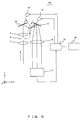
- Fig. 4 is a schematic view illustrating the configuration of the confocal scanning microscope according to the present embodiment.
- An XYZ coordinate system in Fig. 4 is a left-handed orthogonal coordinate system provided for the sake of direction reference.
- a confocal scanning microscope 100 illustrated in Fig. 4 is a confocal microscope provided with a scan unit for scanning a sample, and it includes the aforementioned VPH grating 1 for dispersing fluorescence from the sample and a photodetector 13 for detecting the fluorescence diffracted by the VPH grating 1.
- the photodetector 13 is a multichannel detector on which a plurality of light receiving elements are one-dimensionally arranged.
- the confocal scanning microscope 100 also includes a collective lens 12 for focusing fluorescence onto the photodetector 13, wherein the collective lens 12 is located between the VPH grating 1 and the photodetector 13.
- the confocal scanning microscope 100 includes: a laser light source LS for emitting laser light; an optical fiber 2; a collimator lens 3; a dichroic mirror 4 for reflecting laser light and allowing passage of fluorescence; a galvanometer mirror 5 which is a scan unit for scanning a sample (not shown) placed on a sample plane SP with laser light; an objective 6; a confocal lens 7; a confocal stop 8 having a pinhole at a position conjugate to the focal position of the objective 6; a collimator lens 9; a mirror 10; the VPH grating 1; a mirror 11; the collective lens (collective optical system) 12; the photodetector 13; a control unit 14 for controlling the entirety of the confocal scanning microscope 100; and a drive unit 15 for rotating the VPH grating 1 in accordance with an instruction from the control unit 14.
- the collective lens 12 can be replaced with a concave mirror or the like having positive power.
- the control unit 14 can cause the drive unit 15 to change the tilt angle which is an angle formed by the optical axis of fluorescence incident on the VPH grating 1 and the refractive-index distribution direction of the VPH grating 1. That is, the control unit 14 and the drive unit 15 together function as an incident-angle change unit for changing an incident angle by changing the tilt angle of the VPH grating 1, and the incident-angle change unit can rotate the VPH grating 1 around a rotation axis that is perpendicular to a plane (a YZ plane) parallel to both the optical axis and the refractive-index distribution direction.
- Laser light emitted from the laser light source LS is transmitted through the optical fiber 2 to the collimator lens 3, where it is converted into an essentially parallel light flux, and the essentially parallel light flux is incident on the dichroic mirror 4.
- the laser light is reflected from the dichroic mirror 4 and is incident on the objective 6 via the galvanometer mirror 5.
- the objective 6 focuses the laser light onto one point on a sample placed on the sample plane SP so as to irradiate it. Accordingly, a fluorescence substance within the sample is excited by the laser light.
- the fluorescence from the sample follows the same light path as the one which the laser light follows but proceeds in the direction opposite to the laser light, and hence the fluorescence is incident on the dichroic mirror 4 via the objective 6 and the galvanometer mirror 5.
- the confocal lens 7 focuses the fluorescence having passed through the dichroic mirror 4. Since the confocal stop 8 has a pinhole at a position optically conjugate to the focal position of the objective 6, only the fluorescence generated from the focal position of the objective 6 passes through the confocal stop 8.
- the fluorescence is then converted at the collimator lens 9 into an essentially parallel light flux which is incident on the VPH grating 1 via the mirror 10.
- fluorescence is diffracted so that it is emitted to form a different diffraction angle for each wavelength.
- First order diffracted light (fluorescence) having been emitted to form a different diffraction angle for each wavelength is reflected from the mirror 11 and is then incident on the collective lens 12 so that it forms a different angle with the optical axis for each wavelength.
- the collective lens 12 causes the first order diffracted light to be incident on a different position (light receiving element) of the photodetector 13 for each wavelength, and hence the first order diffracted light is detected by a different channel for each wavelength.
- the first order diffracted light (fluorescence) detected by the photodetector 13 is converted into an electrical signal which is transmitted to the control unit 14.
- the control unit 14 forms a fluorescence image, performs an analyzing process, and the like.
- the fluorescence image and the result of analysis are then displayed on a display unit 29 such as a monitor.
- the VPH grating 1 can achieve higher diffraction efficiency than a surface-relief diffraction grating. Accordingly, in comparison with conventional confocal scanning microscopes using a surface-relieve diffraction grating as a spectroscopic unit, the confocal scanning microscope 100 including the VPH grating 1 is a confocal scanning microscope that is provided with a spectroscopic detection function and that has high light-use efficiency for a wide wavelength region. Therefore, the confocal scanning microscope 100 according to the present embodiment can achieve high light-use efficiency for a wide wavelength region.
- Fig. 2 shows an example in which the wavelength region of light to be detected is within the range of visible light, but this is not particularly required.
- the incident angle of light incident on the VPH grating 1 can be changed by the control unit 14 and the drive unit 15. Via the change in incident angle, the VPH grating 1 can change any wavelength into the Bragg wavelength. Accordingly, by changing the Bragg wavelength depending on the wavelength of fluorescence to be detected, the confocal scanning microscope 100 according to the present embodiment can achieve higher light-use efficiency.
- the fluorescence of the kind most efficiently detected can be optionally selected.
- the Bragg wavelength can be set or selected such that detection efficiency is optimized for the entirety of a wavelength region of interest.
- the VPH grating 1 is a transmissive diffraction grating, and hence, irrespective of incident angles, the direction of the 0-th order diffracted light is fixed. Under the condition of the same wavelength, the exit angle is also essentially fixed irrespective of incident angles. Accordingly, irrespective of incident angles, the first order diffracted light is always emitted in an essentially fixed diffraction direction under the condition of the same wavelength so that it is detected by the same light collector element. Therefore, by rotating the VPH grating 1 so as to change an incident angle, the confocal scanning microscope 100 according to the present embodiment enables the fluorescence most efficiently detected to be optionally selected without changing the wavelength region of light to be detected.
- the Bragg wavelength of light to be most efficiently detected can be changed. Accordingly, in synchrony with the change in the Bragg wavelength which is made by rotating the VPH grating 1, only the signals of a channel corresponding to the Bragg wavelength can be sequentially obtained; therefore, spectral data of high efficiency can be obtained at a high speed for the entire wavelength region of detected light.
- Fig. 5 is a schematic view illustrating the configuration of a confocal scanning microscope according to the present embodiment.
- An XYZ coordinate system in Fig. 5 is a left-handed orthogonal coordinate system provided for the sake of direction reference.
- a confocal scanning microscope 101 according to the present embodiment illustrated in Fig. 5 is different from the confocal scanning microscope 100 according to embodiment 1 in the sense that a mirror 16 (a first mirror), which rotates around an X axis, is provided instead of the mirror 10, that a mirror 17 (a second mirror), which rotates around the X axis, is provided instead of the mirror 11, and that drive units 18 and 19 are provided instead of the drive unit 15.
- the configuration of the confocal scanning microscope 101 according to the present embodiment is similar to that of the confocal scanning microscope 100 illustrated in Fig. 4 . Accordingly, only portions of the configuration of the confocal scanning microscope 101 are shown in Fig. 5 .
- the mirror 16 is located between the galvanometer mirror 5 (not shown) and the VPH grating 1, and it is connected to the drive unit 18 which rotates the mirror 16 around a rotation axis (the X axis) perpendicular to an YZ plane.
- the drive unit 18 is connected to the control unit 14. That is, the drive unit 18 and the control unit 14 together function as an incident-angle change unit for changing an incident angle by rotating the mirror 16 around the rotation axis perpendicular to the YZ plane (X axis).
- the incident-angle change unit of the confocal scanning microscope 101 rotates the mirror 16 instead of the VPH grating 1 in order to change the incident angle. Accordingly, the direction of 0-th order diffracted light also changes depending on the incident angle. Therefore, the diffraction direction of first order diffracted light depends on the incident angle.
- the mirror 17 is located between the VPH grating 1 and the collective lens 12, and it is connected to the drive unit 19 which rotates the mirror 17 around a rotation axis perpendicular to the YZ plane (X axis) .
- the drive unit 19 is connected to the control unit 14.
- the drive unit 19 and the control unit 14 rotate the mirror 17 so that first order diffracted light emitted in a diffraction direction that changes depending on the incident angle is always reflected in a fixed direction for each wavelength. Accordingly, the first order diffracted light is always focused by the collective lens 12 onto a fixedposition for each wavelength, and hence the wavelength region of light to be incident on the light receiving elements of the photodetector 13 is maintained irrespective of incident angles. That is, the drive unit 19 and the control unit 14 together function as a detection-wavelength region maintenance unit which maintains the wavelength region of fluorescence to be detected by the photodetector 13.
- control unit 14 and the drive unit 19 may function as the detection-wavelength region maintenance unit together with the drive unit 18.
- Figs. 6A, 6B and 6C are each a diagram illustrating operations of the mirrors 16 and 17 included in the confocal scanning microscope 101. With reference to Figs. 6A to 6C , descriptions will be given of a method for controlling the mirrors 16 and 17 to maintain the wavelength region of light to be detected irrespective of incident angles.
- a indicate the incident angle of incident light IL incident on the mirror 16
- the incident angle of green first order diffracted light G incident on the mirror 17 let 6 indicate an angle formed by light incident on the VPH grating 1 and the green first order diffracted light G.
- Fig. 6B shows an example in which, in order to change the incident angle, the incident-angle change unit rotates the mirror 16 by angle 5 in the clockwise direction, thereby changing the angle ⁇ formed by normal to the mirror 16 and the incident light IL into an angle ⁇ - ⁇ .
- the incident angle of the light reflected from the mirror 16 and incident on the VPH grating 1 increases by 2 ⁇ . Since the angle of the emission of diffracted light is essentially fixed for each wavelength irrespective of incident angles, the incident angle of the green first order diffracted light G incident on the mirror 17 also increases by 2 ⁇ . Therefore, 2 ⁇ will be the angle formed by the green first order diffracted light G reflected from the mirror 17 before the change of the incident angle and the green first order diffracted light G' reflected from the mirror 17 after the change of the incident angle.
- the detection-wavelength region maintenance unit can rotate the mirror 17 by angle ⁇ in the clockwise direction as with the mirror 16 so as to emit the green first order diffracted light G in the direction parallel to the incident angle IL. Accordingly, the first order diffracted light G is always reflected in a fixed direction irrespective of the incident angle, and hence pieces of first order diffracted light having other wavelengths are also always reflected in fixed directions for each wavelength irrespective of the incident angle. As a result, the wavelength region of fluorescence to be detected by the photodetector 13 is maintained.
- the incident-angle change unit rotates the mirror 16 by angle ⁇ in the counterclockwise direction in order to change the incident angle
- the mirror 17 can be rotated by angle ⁇ in the counterclockwise direction so that the first order diffracted light is always reflected in a fixed direction for each wavelength irrespective of incident angles.
- the wavelength region of fluorescence to be detected by the photodetector 13 is maintained.
- Figs. 6A to 6C each show an example in which the control unit 14 and the drive unit 19 function as a detection-wavelength region maintenance unit which maintains the wavelength region of fluorescence to be detected by the photodetector 13; however, the configuration is not particularly limited to these.
- the control unit 14 and the drive unit 19 do not necessarily need to be operated to maintain the wavelength region of light to be detected, and, instead, they may rotate the mirror 17 and the mirror 16 separately so as to shift the wavelength region of light to be detected.
- the control unit 14 and the drive unit 19 together function as a detection-wavelength region shift unit which controls the center of the wavelength region of light to be detected without changing the bandwidth of fluorescence to be detected by the photodetector 13.
- the control unit 14 and the drive unit 19 may also function as a detection-wavelength region shift unit together with the drive unit 18.
- the confocal scanning microscope 101 because of the inclusion of the VPH grating 1, high light-use efficiency for a wide wavelength region can be achieved as with the confocal scanning microscope 100 according to embodiment 1.
- the confocal scanning microscope 101 can change the incident angle of light incident on the VPH grating 1. As a result, by changing the Bragg wavelength depending on the wavelength of fluorescence to be detected, the confocal scanning microscope 101 can achieve higher light-use efficiency as with the confocal scanning microscope 100 according to embodiment 1. When a plurality of kinds of fluorescence are simultaneously detected, the fluorescence of the kind most efficiently detected can be optionally selected.
- the confocal scanning microscope 101 can maintain the wavelength region of fluorescence to be detected by the photodetector 13. Therefore, as with the confocal scanning microscope 100 according to embodiment 1, the confocal scanning microscope 101 enables the fluorescence most efficiently detected to be optionally selected without changing the wavelength region of light to be detected. In addition, the confocal scanning microscope 101 may also shift the wavelength region of light to be detected.
- Fig. 7A is a schematic view illustrating the configuration of a confocal scanning microscope according to the present embodiment.
- An XYZ coordinate system in Fig. 7A is a left-handed orthogonal coordinate system provided for the sake of direction reference.
- a confocal scanning microscope 102 according to the present embodiment illustrated in Fig. 7A is different from the confocal scanning microscope 100 according to embodiment 1 in the sense that a mirror 17, which rotates around an X axis, is provided instead of the mirror 11 in Fig. 4 according to embodiment 1, and that a drive unit 19, a collective lens 20, a mirror 21a, a mirror 21b, and a drive unit 22 are further provided.
- the configuration of the confocal scanning microscope 102 according to the present embodiment is similar to that of the confocal scanning microscope 100 illustrated in Fig. 4 .
- control unit 14 and the drive unit 15 together function as an incident-angle change unit for changing an incident angle by changing the tilt angle of the VPH grating 1.
- the incident-angle change unit can rotate the VPH grating 1 around a rotation axis that is perpendicular to a plane (a YZ plane) parallel to both the optical axis and the refractive-index distribution direction, and hence it can change the Bragg wavelength.
- the mirror 17 is located between the VPH grating 1 and the collective lens 12, and it is connected to the drive unit 19 which rotates the mirror 17 around a rotation axis (the X axis) perpendicular to an YZ plane (X axis).
- the drive unit 19 is connected to the control unit 14.
- the drive unit 19 and the control unit 14 together function as a detection-wavelength region shift unit which controls the center of the wavelength region of light to be detected.
- the drive unit 19 and the control unit 14 can together function as a detection-wavelength region maintenance unit which maintains the wavelength region of fluorescence to be detected by the photodetector 13.
- the confocal scanning microscope 102 includes a collective lens 12 and a collective lens 20 which are located between the VPH grating 1 and the photodetector 13, which are selectively used, and each of which has a different focal length.
- the collective lens 20 has a greater focal length than the collective lens 12.
- the control unit 14 can cause the drive unit 22 to insert and remove the mirrors 21a and 21b into and from the light path of reflection light from the mirror 17. Via the insertion or the removal of the mirrors, fluorescence is incident on an appropriate lens. Specifically, when the mirrors 21a and 21b are removed from the light path, first order diffracted light reflected from the mirror 17 is focused on the photodetector 13 by the collective lens 12. Meanwhile, when the mirrors 21a and 21b are inserted in the light path, the first order diffracted light reflected from the mirror 17 is incident on the collective lens 20 via the mirror 21a and a mirror 30a. The collective lens 20 focuses the first order diffracted light on the photodetector 13 via a mirror 30b and the mirror 21b.
- the wavelength-dispersion amount becomes larger. Accordingly, in the confocal scanning microscope 102, the width of the wavelength region of fluorescence incident on the photodetector 13 via the collective lens 20 is less than the width of the wavelength region of fluorescence incident on the photodetector 13 via the collective lens 12. In other words, when the wavelength-dispersion amount is small, light within a wide wavelength region; for example, light within the entirety of visible light range, is detected. When the wavelength-dispersion amount is large, light within a narrow wavelength region is detected.
- control unit 14 and the drive unit 22 together function as a bandwidth change unit which changes the width of the wavelength region of fluorescence detected by the photodetector 13.
- bandwidth change unit which changes the width of the wavelength region of fluorescence detected by the photodetector 13.
- the control unit 14 and the drive unit 22 also together function as a wavelength resolution change unit which changes the wavelength resolution.
- the condition in which the wavelength-dispersion amount is small will be hereinafter referred to as a wide band detection condition, and the condition in which the wavelength-dispersion amount is large will be hereinafter referred to as a narrow band detection condition or a high-resolution detection condition.
- the confocal scanning microscope 102 because of the inclusion of the VPH grating 1, high light-use efficiency for a wide wavelength region can be achieved under the wide band detection condition, as with the confocal scanning microscope 100 according to embodiment 1.
- the confocal scanning microscope 102 can change the incident angle of light incident on the VPH grating 1.
- the confocal scanning microscope 102 can achieve higher light-use efficiency as with the confocal scanning microscope 100 according to embodiment 1.
- the fluorescence of the kind most efficiently detected can be optionally selected.
- the confocal scanning microscope 102 can change the width of the wavelength region of fluorescence to be detected. Accordingly, if necessary, the confocal scanning microscope 102 can readily switch between the detection of light within a wide wavelength region under the wide band detection condition and the detection at a high resolution under the narrow band detection condition.
- the confocal scanning microscope 102 can maintain the wavelength region of fluorescence to be detected by the photodetector 13. Therefore, as with the confocal scanning microscope 100 according to embodiment 1, the confocal scanning microscope 102 enables the fluorescence most efficiently detected to be optionally selected without changing the wavelength region of light to be detected. Such a control is particularly effective for the wide band detection condition.
- the confocal scanning microscope 102 can control the center of the wavelength region of light to be detected. As a result of this, the wavelength region of fluorescence to be detected by the photodetector 13 can be shifted. Accordingly, the confocal scanning microscope 102 can readily change the wavelength region of light to be detected aside from changing the Bragg wavelength. Such a control is particularly effective for the narrow band detection condition.
- wavelength region of light to be detected and the Bragg wavelength simultaneously can be achieved through a few detection processes.
- the wavelength region of light to be detected can be shifted seamlessly and the Bragg wavelength can be changed in synchrony with this shit, thereby detecting light within a wide band with a high resolution at high light-use efficiency.
- Fig. 7A shows an example in which the mirrors 21a and 21b are inserted into or removed from the path of detected light so that the condition is switched between the wide band detection condition and the narrow band detection condition (or the high-resolution detection condition); however, the configuration is not particularly limited to this.
- the detection condition may be changed using another method.
- Figs. 7B , 7C and 7D are each a schematic view illustrating a variation of the configuration of the confocal scanning microscope 102 according to the present embodiment.
- a confocal scanning microscope 102a illustrated in Fig. 7B includes a rotatable mirror 31a between the VPH grating 1 and the photodetector 13. Via the control unit 14 causing the drive unit 22 to rotate the mirror 31a, the confocal scanning microscope 102a can switch the condition between the wide band detection condition and the narrow band detection condition.
- first order diffracted light reflected from the mirror 31a is focused on the photodetector 13 by the collective lens 12.
- the wide band detection condition is achieved.
- first order diffracted light reflected from the mirror 31a is incident on a collective lens 32 via a mirror 31b.
- the first order diffracted light is sent via mirrors 31c and 31d and is again incident on and reflected from the mirror 31a.
- the first orderdiffracted light is focused on the photodetector 13 by the collective lens 12.
- first order diffracted light is focused on the photodetector 13 by both the collective lenses 32 and 12.
- a confocal scanning microscope 102b illustrated in Fig. 7C includes a collective lens group 33 located between the VPH grating 1 and the photodetector 13 and composed of a plurality of lenses (collective lenses 33a and 33b) which are capable of moving in the optical-axis direction.
- the collective lens group 33 is a zoom lens (a variable-magnification optical system) which achieves a plurality of zoom states each of which corresponds to a different combinational focal length that depends on the positions of the collective lenses.
- the control unit 14 causing the drive unit 22 to change the zoom state of the collective lens group 33, the confocal scanning microscope 102b can switches the condition between the wide band detection condition and the narrow band detection condition.
- first order diffracted light is focused on the photodetector 13 by the collective lens group 33 providing the short combinational focal length.
- the wide band detection condition is achieved.
- the confocal scanning microscope 102b can consecutively change the detection state from the wide band detection condition to the narrow band detection condition or from the narrow band detection condition to the wide band detection condition.
- a confocal scanning microscope 102c illustrated in Fig. 7D includes a plurality of VPH gratings (VPH gratings 1 and 34) which can be inserted in and removed from the light path.
- the VPH gratings 1 and 34 each have a different grating frequency.
- the VPH grating 1 has a lower grating frequency than the VPH grating 34.
- first order diffracted light indicating a relatively small amount of wavelength-dispersion is focused on the photodetector 13.
- the wide band detection condition is achieved.
- the aforementioned confocal scanning microscopes 102, 102a and 102b change the wavelength-dispersion amount so as to change the detection condition.
- the confocal scanning microscope 102c changes the wavelength-dispersion amount so as to change the detection condition.
- the confocal scanning microscopes according to the variations above i.e., the confocal scanning microscopes 102a, 102b and 102c
- Fig. 8 is a schematic view illustrating the configuration of a confocal scanning microscope according to the present embodiment.
- An XYZ coordinate system in Fig. 8 is a left-handed orthogonal coordinate system provided for the sake of direction reference.
- a confocal scanning microscope 103 illustrated in Fig. 8 is different from the confocal scanning microscope 102 according to embodiment 3 in the sense that a drive unit 18 and a mirror 16 (the first mirror), which rotates around an X axis instead of the mirror 10, are provided and that a mirror 11 is provided instead of the mirror 17 and the drive unit 19.
- the configuration of the confocal scanning microscope 103 according to the present embodiment is similar to that of the confocal scanning microscope 102 illustrated in Fig. 7A .
- the confocal scanning microscope 103 is a confocal scanning microscope that can switch the condition between the wide band detection condition and the narrow band detection condition, and it has an incident-angle change unit, a detection-wavelength region shift unit (a detection-wavelength region maintenance unit), and a bandwidth change unit (a wavelength resolution change unit).
- the control unit 14 and the drive unit 18 together function as the detection-wavelength region shift unit.
- the drive unit 18 and the control unit 14 can together function as the detection-wavelength region maintenance unit which maintains the wavelength region of fluorescence to be detected by the photodetector 13.
- the confocal scanning microscope 103 can change the incident angle. Accordingly, the control unit 14 and the drive unit 15 together function as the incident-angle change unit which changes the incident angle. The incident angle also changes via the rotation of the mirror 16, and hence the control unit 14 and the drive unit 15 may function as the incident-angle change unit together with the drive unit 18.
- control unit 14 and the drive unit 22 together function as the bandwidth change unit which changes the width of the wavelength region of fluorescence to be detected by the photodetector 13.
- the control unit 14 and the drive unit 22 also together function as the wavelength resolution change unit which changes the wavelength resolution.
- the confocal scanning microscope 103 according to the present embodiment can achieve an effect similar to the one achieved by the confocal scanning microscope 102 according to embodiment 3.
- the mirror 11 between the VPH grating 1 and the collective lens 12 (or the collective lens 20) maybe omitted from the confocal scanning microscope 103 according to the present embodiment.
- the distance between the VPH grating 1 and the collective lens is limited in accordance with the focal length of the collective lens. Therefore, the configuration of the confocal scanning microscope 103 according to the present embodiment from which the mirror 11 can be omitted is desirable in the sense that its restriction on layout is small.
- Fig. 9 is a schematic view illustrating the configuration of a confocal scanning microscope according to the present embodiment.
- An XYZ coordinate system in Fig. 9 is a left-handed orthogonal coordinate system provided for the sake of direction reference.
- a confocal scanning microscope 104 illustrated in Fig. 9 is different from the confocal scanning microscope 102 according to embodiment 3 in the sense that a drive unit 18 and a mirror 16 (the first mirror), which rotates around an X axis instead of the mirror 10, are provided and that the drive unit 15 which rotates the VPH grating 1 is not provided.
- the configuration of the confocal scanning microscope 104 according to the present embodiment is similar to that of the confocal scanning microscope 102 illustrated in Fig. 7A .
- the confocal scanning microscope 104 is a confocal scanning microscope that can switch the condition between the wide band detection condition and the narrow band detection condition, and it has an incident-angle change unit, a detection-wavelength region shift unit (a detection-wavelength region maintenance unit), and a bandwidth change unit (a wavelength resolution change unit).
- the control unit 14 Via the control unit 14 causing the drive unit 18 to rotate the mirror 16, the confocal scanning microscope 104 can change the incident angle. Accordingly, the control unit 14 and the drive unit 18 together function as the incident-angle change unit which changes the incident angle.
- the control unit 14 and the drive unit 19 together function as the detection-wavelength region maintenance unit.
- the control unit 14 and the drive unit 19 also together function as the detection-wavelength region shift unit.
- the wavelength region of light to be detected also changes via the rotation of the mirror 16, and hence the control unit 14 and the drive unit 19 may function as the detection-wavelength region maintenance unit or the detection-wavelength region shift unit together with the drive unit 18.
- control unit 14 and the drive unit 22 together function as the bandwidth change unit which changes the width of the wavelength region of fluorescence to be detected by the photodetector 13.
- the control unit 14 and the drive unit 22 also together function as the wavelength resolution change unit which changes the wavelength resolution.
- the confocal scanning microscope 104 can achieve an effect similar to the one achieved by the confocal scanning microscope 102 according to embodiment 3.
- Fig. 10 is a schematic view illustrating the configuration of a confocal scanning microscope according to the present embodiment.
- An XYZ coordinate system in Fig. 10 is a left-handed orthogonal coordinate system provided for the sake of direction reference.
- a confocal scanning microscope 105 according to the present embodiment illustrated in Fig. 10 is different from the confocal scanning microscope 100 according to embodiment 1 mainly in the sense that it includes a plurality of photodetectors (photodetectors 13a and 13b) which are single channel detectors instead of the photodetector 13 which is a multichannel photodetector, and that it includes stop units (step units 28a and 28b) which are located between the photodetectors and collective lenses (collective lenses 12a and 12b) and which limit the width of the wavelength region of fluorescence to be detected by the photodetectors.
- photodetectors 13a and 13b which are single channel detectors instead of the photodetector 13 which is a multichannel photodetector
- stop units 28a and 28b stop units which are located between the photodetectors and collective lenses (collective lenses 12a and 12b) and which limit the width of the wavelength region of fluorescence to be detected by the photodetectors.
- the confocal scanning microscope 105 includes: a laser light source LS; an optical fiber 2; a collimator lens 3; a dichroic mirror 4; a galvanometer mirror 5; an objective 6; a confocal lens 7; a confocal stop 8; and a collimator lens 9.
- the confocal scanning microscope 105 further includes: a mirror 24; a mirror 25; a dichroic mirror 26 (a light-path division unit) that separates fluorescence into two pieces; a mirror 27.
- the confocal scanning microscope 105 further includes: in the reflection-light path of light from the dichroic mirror 26, mirror 10a; VPH grating 1a; mirror 11a; collective lens 12a; stop unit 28a; and photodetector 13a which are single channel detector.
- the confocal scanning microscope 105 further includes: in the transmitted-light path of light from the dichroic mirror 26, mirror 10b; VPH grating 1b; mirror 11b; collective lens 12b; stop unit 28b; and photodetector 13b which are single channel detector.
- Each of the photo detectors (the photodetectors 13a and 13b) can be independently moved in the direction parallel to the light receiving surface of its light receiving elements (Y direction).
- Each of the stop units (the stop units 28a and 28b) can be independently moved in conjunction with the movement of the photodetector, thereby changing the position of the slit (opening). In addition, the widths of the slits (the openings) can be changed.
- the photodetectors and the stop units are connected to a drive unit and a control unit (not shown).
- the control unit and the drive unit (not shown) together function as a detection-wavelength region shift unit which controls the center of the wavelength region of light to be detected by moving the photodetectors and the stop units.
- the control unit and the drive unit (not shown) together function as a bandwidth change unit which changes the width of the wavelength region of fluorescence to be detected by changing the slit widths of the stop units.
- the VPH gratings (the VPH gratings 1a and 1b) are connected to a drive unit and a control unit (not shown).
- the control unit and the drive unit (not shown) together function as an incident-angle change unit which changes the incident angle by changing the tilt angle of each of the VPH gratings.
- the incident-angle change unit can rotate each of the VPH gratings around a rotation axis (an X axis) that is perpendicular to a plane (a YZ plane) parallel to both the optical axis and the refractive-index distribution direction.
- Laser light emitted from the laser light source LS follows a path similar to the one in the confocal scanning microscope 100, and then it irradiates the sample so that a fluorescence substance within the sample is excited. Fluorescence from the sample follows a path similar to the one in the confocal scanning microscope 100, and then it is emitted from the collimator lens 9 as an essentially parallel light flux. After this, the fluorescence is incident on the dichroic mirror 26 via the mirrors 24 and 25.
- the dichroic mirror 26 reflects fluorescence having less than 600 nm of wavelength and allows passage of fluorescence having 600 nm of or greater wavelength.
- the fluorescence reflected from the dichroic mirror 26 is incident on the VPH grating 1a via the mirror 10a, and the VPH grating 1a diffracts the fluorescence.
- the VPH grating 1a is rotated in advance by an incident-angle change unit (not shown) so that the wavelength corresponding to green is the Bragg wavelength, and hence fluorescence G of a wavelength corresponding to green is diffracted most efficiently.
- the fluorescence diffracted by the VPH grating 1a is incident on the collective lens 12a via the mirror 11a and then focused on a different position for each wavelength.
- the detection-wavelength region shift unit moving the photodetector 13a and the stop unit 28a depending on the light-focused position of the fluorescence G of a wavelength corresponding to green
- the fluorescence G of a wavelength corresponding to green can be efficiently detected with the photodetector 13a.
- the bandwidth change unit making the slit width of the stop unit 28a narrower than the light receiving surface of the photodetector 13a
- detection of fluorescence having wavelengths corresponding to the colors other than green can be suppressed. Accordingly, noise components are suppressed, thereby improving the S/N.
- the fluorescence passing through the dichroic mirror 26 is incident on the VPH grating 1b via the mirror 10b, and the VPH grating 1b diffracts the fluorescence.
- the VPH grating 1b is rotated in advance by an incident-angle change unit (not shown) so that the wavelength corresponding to red is the Bragg wavelength, and hence fluorescence R of a wavelength corresponding to red is diffracted most efficiently.
- the fluorescence diffracted by the VPH grating 1b is incident on the collective lens 12b via the mirror 11b and then focused on a different position for each wavelength.
- the detection-wavelength region shift unit moving the photodetector 13b and the stop unit 28b depending on the light-focused position of the fluorescence R of a wavelength corresponding to red
- the fluorescence R of a wavelength corresponding to red can be efficiently detected with the photodetector 13b.
- the bandwidth change unit making the slit width of the stop unit 28b narrower than the light receiving surface of the photodetector 13b
- detection of pieces of fluorescence having wavelengths corresponding to the colors other than red can be suppressed. Accordingly, noise components are suppressed, thereby improving the S/N.
- the confocal scanning microscope 105 can readily change the Bragg wavelength by rotating the VPH grating to change the incident angle. Accordingly, by changing the Bragg wavelength depending on the wavelength of fluorescence to be detected, the confocal scanning microscope 105 can achieve high light-use efficiency.
- the confocal scanning microscope 105 can efficiently detect fluorescence to be detected while suppressing noise. Accordingly, in comparison with a confocal scanning microscope employing a photodetector of multichannel type, a higher S/N can be achieved.
- the confocal scanning microscope 105 has a VPH grating for each wavelength of light to be detected. Accordingly, when pieces of fluorescence each having a different wavelength are simultaneously detected, the VPH gratings can be optimized for the wavelengths. As a result, the confocal scanning microscope 105 can simultaneously achieve high diffraction efficiency for a plurality of wavelengths of fluorescence.
- the configuration in which a VPH grating is provided for each wavelength of light to be detected is especially effective when, for example, the wavelengths of pieces of light to be detected are separated greatly from each other.
- the wavelength region of fluorescence to be incident on each VPH grating is limitedbythedichroicmirror26. Accordingly, the VPH gratings may be designed so that they each achieve high diffraction efficiency for the limited wavelength region. As described above, VPH gratings have a tradeoff between the maximum diffraction efficiency and a bandwidth in which diffracted light can be obtained, and hence higher maximum diffraction efficiency can be obtained by limiting the wavelength region. Therefore, in comparison with a confocal scanning microscope including only a single VPH grating, the confocal scanning microscope 105 can detect fluorescence to be detected more efficiently.
- Fig. 10 illustrates a configuration in which two pieces of light of different wavelengths are simultaneously detected; however, the configuration is not particularly limited to this.
- a mirror may be used instead of the dichroic mirror 26.
- a dichroic mirror i.e., a light-path division unit
- the photodetector to be added is not limited to a detector of single channel type. It may be a detector of multichannel type.
- Fig. 11 is a schematic view illustrating the configuration of a confocal scanning microscope according to the present embodiment.
- An XYZ coordinate system in Fig. 11 is a left-handed orthogonal coordinate system provided for the sake of direction reference.
- a confocal scanning microscope 106 according to the present embodiment illustrated in Fig. 11 is different from the confocal scanning microscope 105 according to embodiment 6 in the sense that mirrors 17a and 17b which rotate around X axes are provided instead of the mirrors 11a and 11b, and that photodetectors (photodetectors 13a and 13b) are fixed.
- the configuration of the confocal scanning microscope 106 according to the present embodiment is similar to that of the confocal scanning microscope 105 illustrated in Fig. 10 . Accordingly, only portions of the configuration of the confocal scanning microscope 106 are shown in Fig. 11 .
- the confocal scanning microscope 106 has an incident-angle change unit, a detection-wavelength region shift unit, and a bandwidth change unit.
- a control unit and a drive unit which change the tilt angles of the VPH gratings 1a and 1b together function as the incident-angle change unit, and a control unit and a drive unit (not shown) which change the slit width of the stop unit together function as the bandwidth change unit.
- control unit (not shown) causing a drive unit (not shown) to rotate the mirrors 17a and 17b
- wavelength region of fluorescence to be incident on the photodetectors can be changed.
- control unit (not shown) and the drive unit (not shown) which rotate the mirrors 17a and 17b together function as a detection-wavelength region shift unit.
- the confocal scanning microscope 106 can achieve an effect similar to the one achieved by the confocal scanning microscope 105 according to embodiment 6.
- the wavelength region of light to be detected is changed by rotating the mirrors not the photodetectors, and hence the confocal scanning microscope 106 can change the wavelength region of light to be detected faster than the confocal scanning microscope 105.
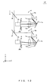
- Fig. 12 is a schematic view illustrating the configuration of a confocal scanning microscope according to the present embodiment.
- An XYZ coordinate system in Fig. 12 is a left-handed orthogonal coordinate system provided for the sake of direction reference.
- a confocal scanning microscope 107 according to the present embodiment illustrated in Fig. 12 is different from the confocal scanning microscope 105 according to embodiment 6 in the sense that mirrors 16a and 16b (first mirrors) which rotate around X axes are provided instead of the mirrors 10a and 10b, and that photodetectors (photodetectors 13a and 13b) are fixed.
- the configuration of the confocal scanning microscope 107 according to the present embodiment is similar to that of the confocal scanning microscope 105 illustrated in Fig. 10 . Accordingly, only portions of the configuration of the confocal scanning microscope 107 are shown in Fig. 12 .
- the confocal scanning microscope 107 has an incident-angle change unit, a detection-wavelength region shift unit, and a bandwidth change unit.
- a control unit and a drive unit which change the slit width of the stop unit together function as the bandwidth change unit.
- the control unit (not shown) and the drive unit (not shown) which rotate the mirrors 16a and 16b together function as a detection-wavelength region shift unit.
- the confocal scanning microscope 107 can change the incident angle.
- the control unit (not shown) and the drive unit (not shown) which rotate the VPH gratings 1a and 1b together function as an incident-angle change unit.
- the incident angle also changes via the rotation of the mirrors 16a and 16b, and hence the control unit (not shown) and the drive unit (not shown) may function as the incident-angle change unit together with the drive unit for the mirrors 16a and 16b.
- the confocal scanning microscope 107 can achieve an effect similar to the one achieved by the confocal scanning microscope 105 according to embodiment 6.
- the wavelength region of light to be detected is changed by rotating the mirrors and the VPH gratings not the photodetectors, and hence the confocal scanning microscope 107 can change the wavelength region of light to be detected faster than the confocal scanning microscope 105.
- Fig. 13 is a schematic view illustrating the configuration of a confocal scanning microscope according to the present embodiment.
- An XYZ coordinate system in Fig. 13 is a left-handed orthogonal coordinate system provided for the sake of direction reference.
- a confocal scanning microscope 108 according to the present embodiment illustrated in Fig. 13 is different from the confocal scanning microscope 105 according to embodiment 6 in the sense that mirrors 16a and 16b (first mirrors) which rotate around X axes are provided instead of the mirrors 10a and 10b, that mirrors 17a and 17b (second mirrors) which rotate around x axes are provided instead of the mirrors 11a and 11b, and that VPH gratings (VPH gratings 1a and 1b) and photodetectors (photodetectors 13a and 13b) are fixed.
- the configuration of the confocal scanning microscope 108 according to the present embodiment is similar to that of the confocal scanning microscope 105 illustrated in Fig. 10 . Accordingly, only portions of the configuration of the confocal scanning microscope 108 are shown in Fig. 13 .
- the confocal scanning microscope 108 has an incident-angle change unit, a detection-wavelength region shift unit, and a bandwidth change unit.
- a control unit and a drive unit which change the slit width of the stop unit together function as the bandwidth change unit.
- the confocal scanning microscope 108 Via a control unit (not shown) causing a drive unit (not shown) to rotate the mirrors 16a and 16b, the confocal scanning microscope 108 can change the incident angle. Accordingly, the control unit (not shown) and the drive unit (not shown) which rotate the mirrors 16a and 16b together function as an incident-angle change unit.
- the wavelength region of light to be detected changes via a drive unit (not shown) rotating the mirrors 17a and 17b.
- the control unit (not shown) and the drive unit (not shown) which rotate the mirrors 17a and 17b together function as a detection-wavelength region shift unit.
- the wavelength region of light to be detected also changes via the rotation of the mirrors 16a and 16b, and hence the control unit (not shown) and the drive unit (not shown) may function as the detection-wavelength region shift unit together with the drive unit for the mirrors 16a and 16b.
- the confocal scanning microscope 108 can achieve an effect similar to the one achieved by the confocal scanning microscope 105 according to embodiment 6.
- the wavelength region of light to be detected is changed by rotating the mirrors not the photodetectors, and hence the confocal scanning microscope 108 can change the wavelength region of light to be detected faster than the confocal scanning microscope 105.
- Each of embodiment1 to embodiment9 shows an example of use of a confocal scanning microscope, but this invention is not particularly limited to use of a confocal scanning microscope. This invention is applicapable to any kind of microscope.
Landscapes
- Physics & Mathematics (AREA)
- Chemical & Material Sciences (AREA)
- Analytical Chemistry (AREA)
- General Physics & Mathematics (AREA)
- Optics & Photonics (AREA)
- Spectroscopy & Molecular Physics (AREA)
- Microscoopes, Condenser (AREA)
- Spectrometry And Color Measurement (AREA)
- Investigating, Analyzing Materials By Fluorescence Or Luminescence (AREA)
- Diffracting Gratings Or Hologram Optical Elements (AREA)
Abstract
Description
- The present invention relates to a scanning microscope and particularly relates to a scanning microscope that has a spectroscopic detection function.
- In recent years, confocal scanning microscopes provided with a spectroscopic detection function have been developed and used. Such a microscope is disclosed in, for example, Japanese Laid-open Patent Publication No.
2006-010944 - Many confocal scanning microscopes provided with a spectroscopic detection function are used for fluorescence observations; however, as a general rule, fluorescence is weak so that the light quantity of the fluorescence obtained per unit time is small. Since a sample observed under a confocal scanning microscope is scanned at a high speed, only a short period of time is spent on exciting each point on the sample. Therefore, in order to obtain a bright image, it is necessary to efficiently lead a limited amount of generated fluorescence to a photodetector.
- As disclosed in Japanese Laid-open Patent Publication No.
2006-010944 - Spectroscopic means is generally an optical element that loses a large quantity of light; accordingly, in a confocal scanning microscope provided with a spectroscopic detection function, suppressing the light loss caused at spectroscopic means is effective to improve light-use efficiency.
- A technology for suppressing light loss caused at spectroscopic means is disclosed in, for example, Japanese Laid-open Patent Publication No.
2006-153587 2006-153587 - Use of the technology disclosed in Japanese Laid-open Patent Publication No.
2006-153587 - However, according to the technology disclosed in Japanese Laid-open Patent Publication No.
2006-153587 - As an example, incident light is divided into P polarized light and S polarized light, which are led through different light paths to a reflective diffraction grating. Accordingly, a polarization beam splitter for diving incident light into P polarized light and S polarized light is used, and light loss will occur at the polarization beam splitter. A wavelength plate for rotating polarized light is used in order to convert P polarized light into S polarized light, and light loss will also occur at the wavelength plate.
- Therefore, even if the diffraction efficiency of the reflective diffraction grating itself is improved, the light-use efficiency of the entirety of the confocal scanning microscope is not improved sufficiently.
- In view of the aforementioned facts, an object of the present invention is to provide a confocal microscope that is provided with a spectroscopic detection function and that has high light-use efficiency for a wide wavelength region.
- A first aspect of the present invention provides a scanning microscope provided with a scan unit that scans a sample, the scanning microscope including: a transmissive VPH grating for dispersing light from the sample; and a photodetector for detecting the light diffracted by the VPH grating.
- The present invention will be more apparent from the following detailed description when the accompanying drawings are referenced.
-
Fig. 1A is a diagram illustrating actions of a VPH grating included in a confocal scanning microscope according toembodiment 1, the VPH grating forming a certain tilt angle. -
Fig. 1B is a diagram illustrating actions of the VPH grating included in the confocal scanning microscope according toembodiment 1, the VPH grating forming a tilt angle different from the one shown inFig. 1A . -
Fig. 1C is a diagram illustrating actions of the VPH grating included in the confocal scanning microscope according toembodiment 1, the VPH grating forming a tilt angle different from the ones shown inFigs. 1A and 1B . -
Fig. 2 is a diagramillustrating the diffraction efficiency of the VPH grating illustrated inFig. 1 . -
Fig. 3A is a diagram illustrating a diffraction provided by a transmissive diffraction grating including a VPH grating, wherein a state of the diffraction in the transmissive diffraction grating is shown. -
Fig. 3B is a diagram illustrating a diffraction provided by the transmissive diffraction grating including the VPH grating, wherein the relationship between a diffraction angle and an exit angle provided by the transmissive diffraction grating is shown. -
Fig. 4 is a schematic view illustrating the configuration of the confocal scanning microscope according toembodiment 1. -
Fig. 5 is a schematic view illustrating the configuration of a confocal scanning microscope according toembodiment 2. -
Fig. 6A is a diagram illustrating operations of mirrors included in the confocal scanning microscope illustrated inFig. 5 . -
Fig. 6B is a diagram illustrating operations of the mirrors included in the confocal scanning microscope illustrated inFig. 5 , wherein a situation is shown in which only the mirror located on the incident side of the VPH grating is operated. -
Fig. 6C is a diagram illustrating operations of the mirrors included in the confocal scanning microscope illustrated inFig. 5 , wherein a situation is shown in which both the mirror located on the incident side of the VPH grating and the mirror located on the emission side are operated. -
Fig. 7A is a schematic view illustrating the configuration of a confocal scanning microscope according toembodiment 3. -
Fig. 7B is a schematic view illustrating a variation of the configuration of the confocal scanning microscope according toembodiment 3. -
Fig. 7C is a schematic view illustrating another variation of the configuration of the confocal scanning microscope according toembodiment 3. -
Fig. 7D is a schematic view illustrating still another variation of the configuration of the confocal scanning microscope according toembodiment 3. -
Fig. 8 is a schematic view illustrating the configuration of a confocal scanning microscope according to embodiment 4. -
Fig. 9 is a schematic view illustrating the configuration of a confocal scanning microscope according toembodiment 5. -
Fig. 10 is a schematic view illustrating the configuration of a confocal scanning microscope according toembodiment 6. -
Fig. 11 is a schematic view illustrating the configuration of a confocal scanning microscope according toembodiment 7. -
Fig. 12 is a schematic view illustrating the configuration of a confocal scanning microscope according toembodiment 8. -
Fig. 13 is a schematic view illustrating the configuration of a confocal scanning microscope according toembodiment 9. - First, before a confocal scanning microscope according to the present embodiment are described, a
VPH grating 1 included in the confocal scanning microscope will be described with reference toFigs. 1A, 1B, 1C , and2 . -
Figs. 1A-1C are each a diagram illustrating actions of a Volume Phase Holographic grating (hereinafter referred to as a VPH grating) included in the confocal scanning microscope according to the present embodiment.Fig. 2 is a diagram illustrating diffraction characteristics of the VPH grating illustrated inFigs. 1A-1C . InFig. 2 , the ordinate and the abscissa indicate a diffraction efficiency (DE) (%) and a wavelength (nm), respectively. Characteristic Cr illustrated inFig. 2 indicates a diffraction characteristic of a surface-relief diffraction grating according to a prior art. Characteristics Ca, Cb, and Cc inFig. 2 indicate diffraction characteristics of the VPH grating 1 according to the present embodiment illustrated inFigs. 1A, 1B and 1C , respectively. - The
VPH grating 1 illustrated inFigs. 1A-1C includes a VPH layer whose refractive index cyclically changes along a main straight-line PL. The direction parallel to the main straight-line PL along which the refractive index cyclically changes will be hereinafter referred to as a refractive-index distribution direction. TheVPH grating 1 is a transmissive diffraction grating that emits 0-th order diffracted light L0 in the direction parallel to incident light IL and emits, for each wavelength, first order diffracted light L1 forming a different angle with the 0-th order diffracted light. TheVPH grating 1 has a diffraction characteristic that can achieve high diffraction efficiency for a wide band in comparison with a surface-relief diffraction grating. - In general, VPH gratings have a tradeoff between the maximum diffraction efficiency and a bandwidth in which diffracted light can be obtained. Accordingly, the diffraction characteristic achieved by VPH gratings has selectivity. As illustrated in
Fig. 2 , the VPH grating 1 according to the present embodiment (see characteristics Ca, Cb, and Cc inFig. 2 ) is a VPH grating designed so that it achieves a diffraction characteristic achieving a higher diffraction efficiency than a surface-relief diffraction grating (see characteristic Cr inFig. 2 ) and achieving a bandwidth as wide as or wider than the surface-relief diffraction grating (see characteristic Cr inFig. 2 ). - As with the diffraction characteristic of a general VPH grating, the diffraction characteristic of the
VPH grating 1 has the following features. - First, depending on an angle θ1 formed by the refractive-index distribution direction and the optical axis of the incident light IL (hereinafter referred to as a tilt angle), the wavelength at the peak of the diffraction efficiency of the first order diffracted light L1 (hereinafter referred to as a first order diffraction efficiency) (this wavelength will be hereinafter referred to as a Bragg wavelength) changes. In other words, depending on an incident angle θ2, the Bragg wavelength changes.
- As an example, in the VPH grating 1 illustrated in
Fig. 1A , the first order diffraction efficiency for the wavelength G (green) is the highest (See characteristic Ca inFig. 2 . A broader arrow indicates a higher diffraction efficiency inFig. 1A ). Meanwhile, when theVPH grating 1 is rotated in the counterclockwise direction so as to increase the tilt angle θ1, then, as illustrated inFig. 1B , the peak of the diffraction efficiency is shifted to the short wavelength side so that the first order diffraction efficiency for the wavelength B (blue) becomes the highest (see characteristic Cb inFig. 2 ). When theVPH grating 1 is rotated in the clockwise direction so as to decrease the tilt angle θ1, then, as illustrated inFig. 1C , the peak of the diffraction efficiency is shifted to the long wavelength side so that the first order diffraction efficiency for the wavelength R (red) becomes the highest (see characteristic Cc inFig. 2 ). - Second, even when the tilt angle θ1 (or the incident angle θ2) changes, the angle formed by the incident light IL and the first order diffracted light remains almost the same under the condition of the same wavelength. Accordingly, the angle formed by the 0-th order diffracted light L0 and the first order diffracted light (hereinafter referred to as an exit angle) also remains almost the same under the condition of the same wavelength. In other words, if the direction of the 0-th order diffracted light L0 is fixed, the emission direction (hereinafter referred to as a diffraction direction) of the first order diffracted light is essentially fixed under the condition of the same wavelength.
-
Figs. 3A and 3B are each a diagram illustrating a diffraction provided by a transmissive diffraction grating including theVPH grating 1.Fig. 3A shows a diffraction in the transmissive diffraction grating.Fig. 3B illustrates a relationship between a diffraction angle and an exit angle provided by the transmissive diffraction grating. With reference toFigs. 3A and 3B , the fact that the diffraction direction typical of the transmissive diffraction grating is essentially fixed irrespective of incident angles will be described. - As illustrated in
Fig. 3A , the exit angle of the first order diffracted light relative to the 0-th light is represented as α+β. Here, α indicates an incident angle relative to a transmissive diffraction grating TG (corresponding to θ2 inFig. 1 ). β indicates the diffraction angle of the first order diffracted light. - In regard to general diffraction gratings including a transmissive diffraction grating, the following formula indicates the relationship between an incident angle α and a diffraction angle β.

- Here, N indicates the grating frequency of the diffraction grating. λ indicates the wavelength of light incident on the diffraction grating.
- When N and λ in the formula (1) are fixed, then, in the vicinity of α=β, the exit angle α+β indicates essentially no changes. Accordingly,in the transmissive diffraction grating, even when the incident angle changes, the exit angle of the first order diffraction light relative to the 0-th order light is essentially fixed under the condition of the same wavelength, and hence the diffraction direction remains essentially fixed irrespective of incident angles. The approximation is precisely established especially when the grating frequency N is low.
- The reason why the
VPH grating 1 has the first feature described above is that the diffraction phenomenon caused at theVPH grating 1 is under the influence of the Bragg condition. Accordingly, the maximum diffraction efficiency of theVPH grating 1 is indicated for the first order diffracted light L1 having a wavelength such that the diffraction angle and the incident angle θ2 are identical with each other. This is because the Bragg condition is satisfied in this situation. The reason why theVPH grating 1 has the second feature described above is that the VPH grating is a transmissive diffraction grating. - Next, the confocal scanning microscope according to the present embodiment will be described.
-
Fig. 4 is a schematic view illustrating the configuration of the confocal scanning microscope according to the present embodiment. An XYZ coordinate system inFig. 4 is a left-handed orthogonal coordinate system provided for the sake of direction reference. - A
confocal scanning microscope 100 illustrated inFig. 4 is a confocal microscope provided with a scan unit for scanning a sample, and it includes the aforementioned VPH grating 1 for dispersing fluorescence from the sample and aphotodetector 13 for detecting the fluorescence diffracted by theVPH grating 1. Thephotodetector 13 is a multichannel detector on which a plurality of light receiving elements are one-dimensionally arranged. Theconfocal scanning microscope 100 also includes acollective lens 12 for focusing fluorescence onto thephotodetector 13, wherein thecollective lens 12 is located between theVPH grating 1 and thephotodetector 13. - More specifically, the
confocal scanning microscope 100 includes: a laser light source LS for emitting laser light; anoptical fiber 2; acollimator lens 3; a dichroic mirror 4 for reflecting laser light and allowing passage of fluorescence; agalvanometer mirror 5 which is a scan unit for scanning a sample (not shown) placed on a sample plane SP with laser light; anobjective 6; aconfocal lens 7; aconfocal stop 8 having a pinhole at a position conjugate to the focal position of theobjective 6; acollimator lens 9; amirror 10; theVPH grating 1; amirror 11; the collective lens (collective optical system) 12; thephotodetector 13; acontrol unit 14 for controlling the entirety of theconfocal scanning microscope 100; and adrive unit 15 for rotating the VPH grating 1 in accordance with an instruction from thecontrol unit 14. - The
collective lens 12 can be replaced with a concave mirror or the like having positive power. - The
control unit 14 can cause thedrive unit 15 to change the tilt angle which is an angle formed by the optical axis of fluorescence incident on theVPH grating 1 and the refractive-index distribution direction of theVPH grating 1. That is, thecontrol unit 14 and thedrive unit 15 together function as an incident-angle change unit for changing an incident angle by changing the tilt angle of theVPH grating 1, and the incident-angle change unit can rotate the VPH grating 1 around a rotation axis that is perpendicular to a plane (a YZ plane) parallel to both the optical axis and the refractive-index distribution direction. - Actions taken by the
confocal scanning microscope 100 during the process from the emission of laser light to the detection of fluorescence will be described. - Laser light emitted from the laser light source LS is transmitted through the
optical fiber 2 to thecollimator lens 3, where it is converted into an essentially parallel light flux, and the essentially parallel light flux is incident on the dichroic mirror 4. In addition, the laser light is reflected from the dichroic mirror 4 and is incident on theobjective 6 via thegalvanometer mirror 5. Theobjective 6 focuses the laser light onto one point on a sample placed on the sample plane SP so as to irradiate it. Accordingly, a fluorescence substance within the sample is excited by the laser light. - The fluorescence from the sample follows the same light path as the one which the laser light follows but proceeds in the direction opposite to the laser light, and hence the fluorescence is incident on the dichroic mirror 4 via the
objective 6 and thegalvanometer mirror 5. Theconfocal lens 7 focuses the fluorescence having passed through the dichroic mirror 4. Since theconfocal stop 8 has a pinhole at a position optically conjugate to the focal position of theobjective 6, only the fluorescence generated from the focal position of the objective 6 passes through theconfocal stop 8. The fluorescence is then converted at thecollimator lens 9 into an essentially parallel light flux which is incident on the VPH grating 1 via themirror 10. - In the
VPH grating 1, fluorescence is diffracted so that it is emitted to form a different diffraction angle for each wavelength. First order diffracted light (fluorescence) having been emitted to form a different diffraction angle for each wavelength is reflected from themirror 11 and is then incident on thecollective lens 12 so that it forms a different angle with the optical axis for each wavelength. Accordingly, thecollective lens 12 causes the first order diffracted light to be incident on a different position (light receiving element) of thephotodetector 13 for each wavelength, and hence the first order diffracted light is detected by a different channel for each wavelength. - The first order diffracted light (fluorescence) detected by the
photodetector 13 is converted into an electrical signal which is transmitted to thecontrol unit 14. On the basis of the electrical signal which is obtained via thegalvanometer mirror 5 scanning the sample and which relates to each point on the sample, thecontrol unit 14 forms a fluorescence image, performs an analyzing process, and the like. The fluorescence image and the result of analysis are then displayed on adisplay unit 29 such as a monitor. - As illustrated in
Fig. 2 , for the entire wavelength region of light to be detected, the VPH grating 1 can achieve higher diffraction efficiency than a surface-relief diffraction grating. Accordingly, in comparison with conventional confocal scanning microscopes using a surface-relieve diffraction grating as a spectroscopic unit, theconfocal scanning microscope 100 including theVPH grating 1 is a confocal scanning microscope that is provided with a spectroscopic detection function and that has high light-use efficiency for a wide wavelength region. Therefore, theconfocal scanning microscope 100 according to the present embodiment can achieve high light-use efficiency for a wide wavelength region. -
Fig. 2 shows an example in which the wavelength region of light to be detected is within the range of visible light, but this is not particularly required. - In the
confocal scanning microscope 100, the incident angle of light incident on the VPH grating 1 can be changed by thecontrol unit 14 and thedrive unit 15. Via the change in incident angle, the VPH grating 1 can change any wavelength into the Bragg wavelength. Accordingly, by changing the Bragg wavelength depending on the wavelength of fluorescence to be detected, theconfocal scanning microscope 100 according to the present embodiment can achieve higher light-use efficiency. When a plurality of kinds of fluorescence are simultaneously detected, the fluorescence of the kind most efficiently detected can be optionally selected. In addition, when a plurality of kinds of fluorescence are simultaneously detected, the Bragg wavelength can be set or selected such that detection efficiency is optimized for the entirety of a wavelength region of interest. - The
VPH grating 1 is a transmissive diffraction grating, and hence, irrespective of incident angles, the direction of the 0-th order diffracted light is fixed. Under the condition of the same wavelength, the exit angle is also essentially fixed irrespective of incident angles. Accordingly, irrespective of incident angles, the first order diffracted light is always emitted in an essentially fixed diffraction direction under the condition of the same wavelength so that it is detected by the same light collector element. Therefore, by rotating the VPH grating 1 so as to change an incident angle, theconfocal scanning microscope 100 according to the present embodiment enables the fluorescence most efficiently detected to be optionally selected without changing the wavelength region of light to be detected. - By changing the incident angle of light incident on the
VPH grating 1, the Bragg wavelength of light to be most efficiently detected can be changed. Accordingly, in synchrony with the change in the Bragg wavelength which is made by rotating theVPH grating 1, only the signals of a channel corresponding to the Bragg wavelength can be sequentially obtained; therefore, spectral data of high efficiency can be obtained at a high speed for the entire wavelength region of detected light. -
Fig. 5 is a schematic view illustrating the configuration of a confocal scanning microscope according to the present embodiment. An XYZ coordinate system inFig. 5 is a left-handed orthogonal coordinate system provided for the sake of direction reference. - A
confocal scanning microscope 101 according to the present embodiment illustrated inFig. 5 is different from theconfocal scanning microscope 100 according toembodiment 1 in the sense that a mirror 16 (a first mirror), which rotates around an X axis, is provided instead of themirror 10, that a mirror 17 (a second mirror), which rotates around the X axis, is provided instead of themirror 11, and thatdrive units drive unit 15. In regard to the points other than these differences, the configuration of theconfocal scanning microscope 101 according to the present embodiment is similar to that of theconfocal scanning microscope 100 illustrated inFig. 4 . Accordingly, only portions of the configuration of theconfocal scanning microscope 101 are shown inFig. 5 . - The
mirror 16 is located between the galvanometer mirror 5 (not shown) and theVPH grating 1, and it is connected to thedrive unit 18 which rotates themirror 16 around a rotation axis (the X axis) perpendicular to an YZ plane. In addition, thedrive unit 18 is connected to thecontrol unit 14. That is, thedrive unit 18 and thecontrol unit 14 together function as an incident-angle change unit for changing an incident angle by rotating themirror 16 around the rotation axis perpendicular to the YZ plane (X axis). - The incident-angle change unit of the
confocal scanning microscope 101 rotates themirror 16 instead of the VPH grating 1 in order to change the incident angle. Accordingly, the direction of 0-th order diffracted light also changes depending on the incident angle. Therefore, the diffraction direction of first order diffracted light depends on the incident angle. - The
mirror 17 is located between theVPH grating 1 and thecollective lens 12, and it is connected to thedrive unit 19 which rotates themirror 17 around a rotation axis perpendicular to the YZ plane (X axis) . In addition, thedrive unit 19 is connected to thecontrol unit 14. - As an example, the
drive unit 19 and thecontrol unit 14 rotate themirror 17 so that first order diffracted light emitted in a diffraction direction that changes depending on the incident angle is always reflected in a fixed direction for each wavelength. Accordingly, the first order diffracted light is always focused by thecollective lens 12 onto a fixedposition for each wavelength, and hence the wavelength region of light to be incident on the light receiving elements of thephotodetector 13 is maintained irrespective of incident angles. That is, thedrive unit 19 and thecontrol unit 14 together function as a detection-wavelength region maintenance unit which maintains the wavelength region of fluorescence to be detected by thephotodetector 13. - Since the wavelength region of light to be detected also changes via the rotation of the
mirror 16, thecontrol unit 14 and thedrive unit 19 may function as the detection-wavelength region maintenance unit together with thedrive unit 18. -
Figs. 6A, 6B and 6C are each a diagram illustrating operations of themirrors confocal scanning microscope 101. With reference toFigs. 6A to 6C , descriptions will be given of a method for controlling themirrors - As illustrated in
Fig. 6A , let a indicate the incident angle of incident light IL incident on themirror 16, let indicate the incident angle of green first order diffracted light G incident on themirror 17, and let 6 indicate an angle formed by light incident on theVPH grating 1 and the green first order diffracted light G. -
Fig. 6B shows an example in which, in order to change the incident angle, the incident-angle change unit rotates themirror 16 byangle 5 in the clockwise direction, thereby changing the angle α formed by normal to themirror 16 and the incident light IL into an angle α-δ. At that time, the incident angle of the light reflected from themirror 16 and incident on the VPH grating 1 increases by 2δ. Since the angle of the emission of diffracted light is essentially fixed for each wavelength irrespective of incident angles, the incident angle of the green first order diffracted light G incident on themirror 17 also increases by 2δ. Therefore, 2δ will be the angle formed by the green first order diffracted light G reflected from themirror 17 before the change of the incident angle and the green first order diffracted light G' reflected from themirror 17 after the change of the incident angle. - As illustrated in
Fig. 6C , the detection-wavelength region maintenance unit can rotate themirror 17 by angle δ in the clockwise direction as with themirror 16 so as to emit the green first order diffracted light G in the direction parallel to the incident angle IL. Accordingly, the first order diffracted light G is always reflected in a fixed direction irrespective of the incident angle, and hence pieces of first order diffracted light having other wavelengths are also always reflected in fixed directions for each wavelength irrespective of the incident angle. As a result, the wavelength region of fluorescence to be detected by thephotodetector 13 is maintained. - Similarly, when the incident-angle change unit rotates the
mirror 16 by angle δ in the counterclockwise direction in order to change the incident angle, themirror 17 can be rotated by angle δ in the counterclockwise direction so that the first order diffracted light is always reflected in a fixed direction for each wavelength irrespective of incident angles. In other words, by rotating themirror 16 and themirror 17 in the same direction by the same angle, the wavelength region of fluorescence to be detected by thephotodetector 13 is maintained. -
Figs. 6A to 6C each show an example in which thecontrol unit 14 and thedrive unit 19 function as a detection-wavelength region maintenance unit which maintains the wavelength region of fluorescence to be detected by thephotodetector 13; however, the configuration is not particularly limited to these. Thecontrol unit 14 and thedrive unit 19 do not necessarily need to be operated to maintain the wavelength region of light to be detected, and, instead, they may rotate themirror 17 and themirror 16 separately so as to shift the wavelength region of light to be detected. In such a case, thecontrol unit 14 and thedrive unit 19 together function as a detection-wavelength region shift unit which controls the center of the wavelength region of light to be detected without changing the bandwidth of fluorescence to be detected by thephotodetector 13. Thecontrol unit 14 and thedrive unit 19 may also function as a detection-wavelength region shift unit together with thedrive unit 18. - According to the
confocal scanning microscope 101 according to the present embodiment, because of the inclusion of theVPH grating 1, high light-use efficiency for a wide wavelength region can be achieved as with theconfocal scanning microscope 100 according toembodiment 1. - Via the
control unit 14 and thedrive unit 18 rotating themirror 16, theconfocal scanning microscope 101 can change the incident angle of light incident on theVPH grating 1. As a result, by changing the Bragg wavelength depending on the wavelength of fluorescence to be detected, theconfocal scanning microscope 101 can achieve higher light-use efficiency as with theconfocal scanning microscope 100 according toembodiment 1. When a plurality of kinds of fluorescence are simultaneously detected, the fluorescence of the kind most efficiently detected can be optionally selected. - Via the
control unit 14 and thedrive unit 19 rotating themirror 17, theconfocal scanning microscope 101 can maintain the wavelength region of fluorescence to be detected by thephotodetector 13. Therefore, as with theconfocal scanning microscope 100 according toembodiment 1, theconfocal scanning microscope 101 enables the fluorescence most efficiently detected to be optionally selected without changing the wavelength region of light to be detected. In addition, theconfocal scanning microscope 101 may also shift the wavelength region of light to be detected. -
Fig. 7A is a schematic view illustrating the configuration of a confocal scanning microscope according to the present embodiment. An XYZ coordinate system inFig. 7A is a left-handed orthogonal coordinate system provided for the sake of direction reference. - A
confocal scanning microscope 102 according to the present embodiment illustrated inFig. 7A is different from theconfocal scanning microscope 100 according toembodiment 1 in the sense that amirror 17, which rotates around an X axis, is provided instead of themirror 11 inFig. 4 according toembodiment 1, and that adrive unit 19, acollective lens 20, amirror 21a, amirror 21b, and adrive unit 22 are further provided. In regard to the points other than these differences, the configuration of theconfocal scanning microscope 102 according to the present embodiment is similar to that of theconfocal scanning microscope 100 illustrated inFig. 4 . - As with the case in
embodiment 1, thecontrol unit 14 and thedrive unit 15 together function as an incident-angle change unit for changing an incident angle by changing the tilt angle of theVPH grating 1. The incident-angle change unit can rotate the VPH grating 1 around a rotation axis that is perpendicular to a plane (a YZ plane) parallel to both the optical axis and the refractive-index distribution direction, and hence it can change the Bragg wavelength. - The
mirror 17 is located between theVPH grating 1 and thecollective lens 12, and it is connected to thedrive unit 19 which rotates themirror 17 around a rotation axis (the X axis) perpendicular to an YZ plane (X axis). In addition, thedrive unit 19 is connected to thecontrol unit 14. - As with the case in
embodiment 2, thedrive unit 19 and thecontrol unit 14 together function as a detection-wavelength region shift unit which controls the center of the wavelength region of light to be detected. When a control is performed such that themirror 17 is not operated, thedrive unit 19 and thecontrol unit 14 can together function as a detection-wavelength region maintenance unit which maintains the wavelength region of fluorescence to be detected by thephotodetector 13. - The
confocal scanning microscope 102 includes acollective lens 12 and acollective lens 20 which are located between theVPH grating 1 and thephotodetector 13, which are selectively used, and each of which has a different focal length. Thecollective lens 20 has a greater focal length than thecollective lens 12. - The
control unit 14 can cause thedrive unit 22 to insert and remove themirrors mirror 17. Via the insertion or the removal of the mirrors, fluorescence is incident on an appropriate lens. Specifically, when themirrors mirror 17 is focused on thephotodetector 13 by thecollective lens 12. Meanwhile, when themirrors mirror 17 is incident on thecollective lens 20 via themirror 21a and amirror 30a. Thecollective lens 20 focuses the first order diffracted light on thephotodetector 13 via amirror 30b and themirror 21b. - In general, as the focal length becomes greater or as the grating frequency of the diffraction grating becomes higher, the wavelength-dispersion amount becomes larger. Accordingly, in the
confocal scanning microscope 102, the width of the wavelength region of fluorescence incident on thephotodetector 13 via thecollective lens 20 is less than the width of the wavelength region of fluorescence incident on thephotodetector 13 via thecollective lens 12. In other words, when the wavelength-dispersion amount is small, light within a wide wavelength region; for example, light within the entirety of visible light range, is detected. When the wavelength-dispersion amount is large, light within a narrow wavelength region is detected. - Accordingly, the
control unit 14 and thedrive unit 22 together function as a bandwidth change unit which changes the width of the wavelength region of fluorescence detected by thephotodetector 13. In inverse proportion to the width of the wavelength region of fluorescence incident on thephotodetector 13, the bandwidth of fluorescence incident on each light receiving element decreases so that the resolution is improved. As a result, thecontrol unit 14 and thedrive unit 22 also together function as a wavelength resolution change unit which changes the wavelength resolution. - The condition in which the wavelength-dispersion amount is small will be hereinafter referred to as a wide band detection condition, and the condition in which the wavelength-dispersion amount is large will be hereinafter referred to as a narrow band detection condition or a high-resolution detection condition.
- As described above, according to the
confocal scanning microscope 102 according to the present embodiment, because of the inclusion of theVPH grating 1, high light-use efficiency for a wide wavelength region can be achieved under the wide band detection condition, as with theconfocal scanning microscope 100 according toembodiment 1. - Via the
control unit 14 and thedrive unit 15 rotating theVPH grating 1, theconfocal scanning microscope 102 can change the incident angle of light incident on theVPH grating 1. As a result, by changing the Bragg wavelength depending on the wavelength of fluorescence to be detected, theconfocal scanning microscope 102 can achieve higher light-use efficiency as with theconfocal scanning microscope 100 according toembodiment 1. When a plurality of kinds of fluorescence are simultaneously detected, the fluorescence of the kind most efficiently detected can be optionally selected. - Via the
control unit 14 and thedrive unit 22 inserting and removing themirrors confocal scanning microscope 102 can change the width of the wavelength region of fluorescence to be detected. Accordingly, if necessary, theconfocal scanning microscope 102 can readily switch between the detection of light within a wide wavelength region under the wide band detection condition and the detection at a high resolution under the narrow band detection condition. - In addition, via the
control unit 14 and thedrive unit 19 rotating themirror 17, theconfocal scanning microscope 102 can maintain the wavelength region of fluorescence to be detected by thephotodetector 13. Therefore, as with theconfocal scanning microscope 100 according toembodiment 1, theconfocal scanning microscope 102 enables the fluorescence most efficiently detected to be optionally selected without changing the wavelength region of light to be detected. Such a control is particularly effective for the wide band detection condition. - Via the
control unit 14 and thedrive unit 19 rotating themirror 17, theconfocal scanning microscope 102 can control the center of the wavelength region of light to be detected. As a result of this, the wavelength region of fluorescence to be detected by thephotodetector 13 can be shifted. Accordingly, theconfocal scanning microscope 102 can readily change the wavelength region of light to be detected aside from changing the Bragg wavelength. Such a control is particularly effective for the narrow band detection condition. - By changing the wavelength region of light to be detected and the Bragg wavelength simultaneously depending on the wavelength of fluorescence to be detected, high light-use efficiency can be achieved through a few detection processes. The wavelength region of light to be detected can be shifted seamlessly and the Bragg wavelength can be changed in synchrony with this shit, thereby detecting light within a wide band with a high resolution at high light-use efficiency.
-
Fig. 7A shows an example in which themirrors -
Figs. 7B ,7C and7D are each a schematic view illustrating a variation of the configuration of theconfocal scanning microscope 102 according to the present embodiment. - A
confocal scanning microscope 102a illustrated inFig. 7B includes arotatable mirror 31a between theVPH grating 1 and thephotodetector 13. Via thecontrol unit 14 causing thedrive unit 22 to rotate themirror 31a, theconfocal scanning microscope 102a can switch the condition between the wide band detection condition and the narrow band detection condition. - Specifically, when the
mirror 31a is in a first condition (i.e., the condition in which themirror 31a is indicated by the solid line), first order diffracted light reflected from themirror 31a is focused on thephotodetector 13 by thecollective lens 12. As a result, the wide band detection condition is achieved. - Meanwhile, when the
mirror 31a is in a second condition (i.e., the condition in which themirror 31a is indicated by the dashed line), first order diffracted light reflected from themirror 31a is incident on acollective lens 32 via amirror 31b. In addition, the first order diffracted light is sent viamirrors mirror 31a. Then, the first orderdiffracted light is focused on thephotodetector 13 by thecollective lens 12. In other words, when themirror 31a is in the second condition, first order diffracted light is focused on thephotodetector 13 by both thecollective lenses - A
confocal scanning microscope 102b illustrated inFig. 7C includes acollective lens group 33 located between theVPH grating 1 and thephotodetector 13 and composed of a plurality of lenses (collective lenses collective lens group 33 is a zoom lens (a variable-magnification optical system) which achieves a plurality of zoom states each of which corresponds to a different combinational focal length that depends on the positions of the collective lenses. Via thecontrol unit 14 causing thedrive unit 22 to change the zoom state of thecollective lens group 33, theconfocal scanning microscope 102b can switches the condition between the wide band detection condition and the narrow band detection condition. - Specifically, when the
collective lenses collective lens group 33 is short (i.e., the condition in which thecollective lenses photodetector 13 by thecollective lens group 33 providing the short combinational focal length. As a result, the wide band detection condition is achieved. - Meanwhile, when the
collective lenses collective lens group 33 is long (i.e., the condition in which thecollective lenses photodetector 13 by thecollective lens group 33 providing the long combinational focal length. As a result, the narrow band detection condition is achieved. - Via the collective lenses being moved in the optical-axis direction, the
confocal scanning microscope 102b can consecutively change the detection state from the wide band detection condition to the narrow band detection condition or from the narrow band detection condition to the wide band detection condition. - A
confocal scanning microscope 102c illustrated inFig. 7D includes a plurality of VPH gratings (VPH gratings 1 and 34) which can be inserted in and removed from the light path. TheVPH gratings 1 and 34 each have a different grating frequency. TheVPH grating 1 has a lower grating frequency than the VPH grating 34. Via thecontrol unit 14 causing thedrive unit 22 to switch the VPH grating inserted in the light path, theconfocal scanning microscope 102c can switch the condition between the wide band detection condition and the narrow band detection condition. - Specifically, under a first condition in which the
VPH grating 1 is inserted in the light path, first order diffracted light indicating a relatively small amount of wavelength-dispersion is focused on thephotodetector 13. As a result, the wide band detection condition is achieved. - Meanwhile, under a second condition in which the VPH grating 34 is inserted in the light path, first order diffracted light indicating a relatively large amount of wavelength-dispersion is focused on the
photodetector 13. As a result, the narrow band detection condition is achieved. - By changing the focal lengths of the collective lenses (group) located between the
VPH grating 1 and thephotodetector 13, the aforementionedconfocal scanning microscopes confocal scanning microscope 102c changes the wavelength-dispersion amount so as to change the detection condition. - The confocal scanning microscopes according to the variations above (i.e., the
confocal scanning microscopes confocal scanning microscope 102 according to the present embodiment. -
Fig. 8 is a schematic view illustrating the configuration of a confocal scanning microscope according to the present embodiment. An XYZ coordinate system inFig. 8 is a left-handed orthogonal coordinate system provided for the sake of direction reference. - A
confocal scanning microscope 103 illustrated inFig. 8 is different from theconfocal scanning microscope 102 according toembodiment 3 in the sense that adrive unit 18 and a mirror 16 (the first mirror), which rotates around an X axis instead of themirror 10, are provided and that amirror 11 is provided instead of themirror 17 and thedrive unit 19. In regard to the points other than these differences, the configuration of theconfocal scanning microscope 103 according to the present embodiment is similar to that of theconfocal scanning microscope 102 illustrated inFig. 7A . - As with the
confocal scanning microscope 102 according toembodiment 3, theconfocal scanning microscope 103 according to the present embodiment is a confocal scanning microscope that can switch the condition between the wide band detection condition and the narrow band detection condition, and it has an incident-angle change unit, a detection-wavelength region shift unit (a detection-wavelength region maintenance unit), and a bandwidth change unit (a wavelength resolution change unit). - In the
confocal scanning microscope 103, since themirror 11 is fixed, the wavelength region of light to be detected changes only via the rotation of themirror 16. Accordingly, thecontrol unit 14 and thedrive unit 18 together function as the detection-wavelength region shift unit. When a control is performed such that themirror 16 is not operated, thedrive unit 18 and thecontrol unit 14 can together function as the detection-wavelength region maintenance unit which maintains the wavelength region of fluorescence to be detected by thephotodetector 13. - Via the
control unit 14 causing thedrive unit 15 to rotate theVPH grating 1, theconfocal scanning microscope 103 can change the incident angle. Accordingly, thecontrol unit 14 and thedrive unit 15 together function as the incident-angle change unit which changes the incident angle. The incident angle also changes via the rotation of themirror 16, and hence thecontrol unit 14 and thedrive unit 15 may function as the incident-angle change unit together with thedrive unit 18. - As with the case in
embodiment 3, thecontrol unit 14 and thedrive unit 22 together function as the bandwidth change unit which changes the width of the wavelength region of fluorescence to be detected by thephotodetector 13. Thecontrol unit 14 and thedrive unit 22 also together function as the wavelength resolution change unit which changes the wavelength resolution. - As described above, the
confocal scanning microscope 103 according to the present embodiment can achieve an effect similar to the one achieved by theconfocal scanning microscope 102 according toembodiment 3. - The
mirror 11 between theVPH grating 1 and the collective lens 12 (or the collective lens 20) maybe omitted from theconfocal scanning microscope 103 according to the present embodiment. The distance between theVPH grating 1 and the collective lens is limited in accordance with the focal length of the collective lens. Therefore, the configuration of theconfocal scanning microscope 103 according to the present embodiment from which themirror 11 can be omitted is desirable in the sense that its restriction on layout is small. -
Fig. 9 is a schematic view illustrating the configuration of a confocal scanning microscope according to the present embodiment. An XYZ coordinate system inFig. 9 is a left-handed orthogonal coordinate system provided for the sake of direction reference. - A
confocal scanning microscope 104 illustrated inFig. 9 is different from theconfocal scanning microscope 102 according toembodiment 3 in the sense that adrive unit 18 and a mirror 16 (the first mirror), which rotates around an X axis instead of themirror 10, are provided and that thedrive unit 15 which rotates theVPH grating 1 is not provided. In regard to the points other than these differences, the configuration of theconfocal scanning microscope 104 according to the present embodiment is similar to that of theconfocal scanning microscope 102 illustrated inFig. 7A . - As with the
confocal scanning microscope 102 according toembodiment 3, theconfocal scanning microscope 104 according to the present embodiment is a confocal scanning microscope that can switch the condition between the wide band detection condition and the narrow band detection condition, and it has an incident-angle change unit, a detection-wavelength region shift unit (a detection-wavelength region maintenance unit), and a bandwidth change unit (a wavelength resolution change unit). - Via the
control unit 14 causing thedrive unit 18 to rotate themirror 16, theconfocal scanning microscope 104 can change the incident angle. Accordingly, thecontrol unit 14 and thedrive unit 18 together function as the incident-angle change unit which changes the incident angle. - As with the case in
embodiment 2, via the drivingunit 19 rotating themirrors confocal scanning microscope 104 can focus first order diffracted light on the same position for each wavelength. Accordingly, thecontrol unit 14 and thedrive unit 19 together function as the detection-wavelength region maintenance unit. By making the rotation angle of themirror 17 different from that of themirror 16, thecontrol unit 14 and thedrive unit 19 also together function as the detection-wavelength region shift unit. The wavelength region of light to be detected also changes via the rotation of themirror 16, and hence thecontrol unit 14 and thedrive unit 19 may function as the detection-wavelength region maintenance unit or the detection-wavelength region shift unit together with thedrive unit 18. - As with the case in
embodiment 3, thecontrol unit 14 and thedrive unit 22 together function as the bandwidth change unit which changes the width of the wavelength region of fluorescence to be detected by thephotodetector 13. Thecontrol unit 14 and thedrive unit 22 also together function as the wavelength resolution change unit which changes the wavelength resolution. - As described above, the
confocal scanning microscope 104 according to the present embodiment can achieve an effect similar to the one achieved by theconfocal scanning microscope 102 according toembodiment 3. -
Fig. 10 is a schematic view illustrating the configuration of a confocal scanning microscope according to the present embodiment. An XYZ coordinate system inFig. 10 is a left-handed orthogonal coordinate system provided for the sake of direction reference. - A
confocal scanning microscope 105 according to the present embodiment illustrated inFig. 10 is different from theconfocal scanning microscope 100 according toembodiment 1 mainly in the sense that it includes a plurality of photodetectors (photodetectors photodetector 13 which is a multichannel photodetector, and that it includes stop units (step units collective lenses - As with the
confocal scanning microscope 100, theconfocal scanning microscope 105 includes: a laser light source LS; anoptical fiber 2; acollimator lens 3; a dichroic mirror 4; agalvanometer mirror 5; anobjective 6; aconfocal lens 7; aconfocal stop 8; and acollimator lens 9. - The
confocal scanning microscope 105 further includes: amirror 24; amirror 25; a dichroic mirror 26 (a light-path division unit) that separates fluorescence into two pieces; amirror 27. - The
confocal scanning microscope 105 further includes: in the reflection-light path of light from thedichroic mirror 26,mirror 10a; VPH grating 1a;mirror 11a;collective lens 12a; stopunit 28a; andphotodetector 13a which are single channel detector. - The
confocal scanning microscope 105 further includes: in the transmitted-light path of light from thedichroic mirror 26,mirror 10b; VPH grating 1b;mirror 11b;collective lens 12b; stopunit 28b; andphotodetector 13b which are single channel detector. - Each of the photo detectors (the
photodetectors stop units - The photodetectors and the stop units are connected to a drive unit and a control unit (not shown). The control unit and the drive unit (not shown) together function as a detection-wavelength region shift unit which controls the center of the wavelength region of light to be detected by moving the photodetectors and the stop units. The control unit and the drive unit (not shown) together function as a bandwidth change unit which changes the width of the wavelength region of fluorescence to be detected by changing the slit widths of the stop units.
- The VPH gratings (the
VPH gratings - Using an exemplary situation in which fluorescence of a wavelength corresponding to red and fluorescence of a wavelength corresponding to green are simultaneously detected by the
dichroic mirror 26 which reflects fluorescence having less than 600 nm of wavelength, descriptions will be given regarding actions taken by theconfocal scanning microscope 105 from the emission of laser light to the detection of fluorescence. - Laser light emitted from the laser light source LS follows a path similar to the one in the
confocal scanning microscope 100, and then it irradiates the sample so that a fluorescence substance within the sample is excited. Fluorescence from the sample follows a path similar to the one in theconfocal scanning microscope 100, and then it is emitted from thecollimator lens 9 as an essentially parallel light flux. After this, the fluorescence is incident on thedichroic mirror 26 via themirrors dichroic mirror 26 reflects fluorescence having less than 600 nm of wavelength and allows passage of fluorescence having 600 nm of or greater wavelength. - The fluorescence reflected from the
dichroic mirror 26 is incident on the VPH grating 1a via themirror 10a, and the VPH grating 1a diffracts the fluorescence. Here, the VPH grating 1a is rotated in advance by an incident-angle change unit (not shown) so that the wavelength corresponding to green is the Bragg wavelength, and hence fluorescence G of a wavelength corresponding to green is diffracted most efficiently. The fluorescence diffracted by the VPH grating 1a is incident on thecollective lens 12a via themirror 11a and then focused on a different position for each wavelength. - As a result, via the detection-wavelength region shift unit moving the
photodetector 13a and thestop unit 28a depending on the light-focused position of the fluorescence G of a wavelength corresponding to green, the fluorescence G of a wavelength corresponding to green can be efficiently detected with thephotodetector 13a. Via the bandwidth change unit making the slit width of thestop unit 28a narrower than the light receiving surface of thephotodetector 13a, detection of fluorescence having wavelengths corresponding to the colors other than green can be suppressed. Accordingly, noise components are suppressed, thereby improving the S/N. - Meanwhile, the fluorescence passing through the
dichroic mirror 26 is incident on the VPH grating 1b via themirror 10b, and the VPH grating 1b diffracts the fluorescence. Here, the VPH grating 1b is rotated in advance by an incident-angle change unit (not shown) so that the wavelength corresponding to red is the Bragg wavelength, and hence fluorescence R of a wavelength corresponding to red is diffracted most efficiently. The fluorescence diffracted by the VPH grating 1b is incident on thecollective lens 12b via themirror 11b and then focused on a different position for each wavelength. - As a result, via the detection-wavelength region shift unit moving the
photodetector 13b and thestop unit 28b depending on the light-focused position of the fluorescence R of a wavelength corresponding to red, the fluorescence R of a wavelength corresponding to red can be efficiently detected with thephotodetector 13b. Via the bandwidth change unit making the slit width of thestop unit 28b narrower than the light receiving surface of thephotodetector 13b, detection of pieces of fluorescence having wavelengths corresponding to the colors other than red can be suppressed. Accordingly, noise components are suppressed, thereby improving the S/N. - As with the
confocal scanning microscope 100 according toembodiment 1, theconfocal scanning microscope 105 according to the present embodiment can readily change the Bragg wavelength by rotating the VPH grating to change the incident angle. Accordingly, by changing the Bragg wavelength depending on the wavelength of fluorescence to be detected, theconfocal scanning microscope 105 can achieve high light-use efficiency. - Using the combination of a photodetector of single channel type and a stop unit, the
confocal scanning microscope 105 according to the present embodiment can efficiently detect fluorescence to be detected while suppressing noise. Accordingly, in comparison with a confocal scanning microscope employing a photodetector of multichannel type, a higher S/N can be achieved. - The
confocal scanning microscope 105 has a VPH grating for each wavelength of light to be detected. Accordingly, when pieces of fluorescence each having a different wavelength are simultaneously detected, the VPH gratings can be optimized for the wavelengths. As a result, theconfocal scanning microscope 105 can simultaneously achieve high diffraction efficiency for a plurality of wavelengths of fluorescence. The configuration in which a VPH grating is provided for each wavelength of light to be detected is especially effective when, for example, the wavelengths of pieces of light to be detected are separated greatly from each other. - In the
confocal scanning microscope 105, the wavelength region of fluorescence to be incident on each VPH grating is limitedbythedichroicmirror26. Accordingly, the VPH gratings may be designed so that they each achieve high diffraction efficiency for the limited wavelength region. As described above, VPH gratings have a tradeoff between the maximum diffraction efficiency and a bandwidth in which diffracted light can be obtained, and hence higher maximum diffraction efficiency can be obtained by limiting the wavelength region. Therefore, in comparison with a confocal scanning microscope including only a single VPH grating, theconfocal scanning microscope 105 can detect fluorescence to be detected more efficiently. - For simplicity,
Fig. 10 illustrates a configuration in which two pieces of light of different wavelengths are simultaneously detected; however, the configuration is not particularly limited to this. If detecting only light of a single wavelength is enough, a mirror may be used instead of thedichroic mirror 26. When it is necessary to simultaneously detect three or more pieces of light of different wavelengths, a dichroic mirror (i.e., a light-path division unit) may be used instead of themirror 27 so as to add a photodetector. The photodetector to be added is not limited to a detector of single channel type. It may be a detector of multichannel type. -
Fig. 11 is a schematic view illustrating the configuration of a confocal scanning microscope according to the present embodiment. An XYZ coordinate system inFig. 11 is a left-handed orthogonal coordinate system provided for the sake of direction reference. - A
confocal scanning microscope 106 according to the present embodiment illustrated inFig. 11 is different from theconfocal scanning microscope 105 according toembodiment 6 in the sense that mirrors 17a and 17b which rotate around X axes are provided instead of themirrors photodetectors confocal scanning microscope 106 according to the present embodiment is similar to that of theconfocal scanning microscope 105 illustrated inFig. 10 . Accordingly, only portions of the configuration of theconfocal scanning microscope 106 are shown inFig. 11 . - As with the
confocal scanning microscope 105 according toembodiment 6, theconfocal scanning microscope 106 according to the present embodiment has an incident-angle change unit, a detection-wavelength region shift unit, and a bandwidth change unit. - As with the
confocal scanning microscope 105 according toembodiment 6, in theconfocal scanning microscope 106, a control unit and a drive unit (not shown) which change the tilt angles of theVPH gratings - In the
confocal scanning microscope 106, via a control unit (not shown) causing a drive unit (not shown) to rotate themirrors mirrors - As described above, the
confocal scanning microscope 106 according to the present embodiment can achieve an effect similar to the one achieved by theconfocal scanning microscope 105 according toembodiment 6. In addition, in theconfocal scanning microscope 106, the wavelength region of light to be detected is changed by rotating the mirrors not the photodetectors, and hence theconfocal scanning microscope 106 can change the wavelength region of light to be detected faster than theconfocal scanning microscope 105. -
Fig. 12 is a schematic view illustrating the configuration of a confocal scanning microscope according to the present embodiment. An XYZ coordinate system inFig. 12 is a left-handed orthogonal coordinate system provided for the sake of direction reference. - A
confocal scanning microscope 107 according to the present embodiment illustrated inFig. 12 is different from theconfocal scanning microscope 105 according toembodiment 6 in the sense that mirrors 16a and 16b (first mirrors) which rotate around X axes are provided instead of themirrors photodetectors confocal scanning microscope 107 according to the present embodiment is similar to that of theconfocal scanning microscope 105 illustrated inFig. 10 . Accordingly, only portions of the configuration of theconfocal scanning microscope 107 are shown inFig. 12 . - As with the
confocal scanning microscope 105 according toembodiment 6, theconfocal scanning microscope 107 according to the present embodiment has an incident-angle change unit, a detection-wavelength region shift unit, and a bandwidth change unit. - As with the
confocal scanning microscope 105 according toembodiment 6, in theconfocal scanning microscope 107, a control unit and a drive unit (not shown) which change the slit width of the stop unit together function as the bandwidth change unit. - In the
confocal scanning microscope 107, since themirrors mirrors mirrors - Via a control unit (not shown) causing a drive unit (not shown) to rotate the
VPH gratings confocal scanning microscope 107 can change the incident angle. Accordingly, the control unit (not shown) and the drive unit (not shown) which rotate theVPH gratings mirrors mirrors - As described above, the
confocal scanning microscope 107 according to the present embodiment can achieve an effect similar to the one achieved by theconfocal scanning microscope 105 according toembodiment 6. In addition, in theconfocal scanning microscope 107, the wavelength region of light to be detected is changed by rotating the mirrors and the VPH gratings not the photodetectors, and hence theconfocal scanning microscope 107 can change the wavelength region of light to be detected faster than theconfocal scanning microscope 105. -
Fig. 13 is a schematic view illustrating the configuration of a confocal scanning microscope according to the present embodiment. An XYZ coordinate system inFig. 13 is a left-handed orthogonal coordinate system provided for the sake of direction reference. - A
confocal scanning microscope 108 according to the present embodiment illustrated inFig. 13 is different from theconfocal scanning microscope 105 according toembodiment 6 in the sense that mirrors 16a and 16b (first mirrors) which rotate around X axes are provided instead of themirrors mirrors VPH gratings photodetectors confocal scanning microscope 108 according to the present embodiment is similar to that of theconfocal scanning microscope 105 illustrated inFig. 10 . Accordingly, only portions of the configuration of theconfocal scanning microscope 108 are shown inFig. 13 . - As with the
confocal scanning microscope 105 according toembodiment 6, theconfocal scanning microscope 108 according to the present embodiment has an incident-angle change unit, a detection-wavelength region shift unit, and a bandwidth change unit. - As with the
confocal scanning microscope 105 according toembodiment 6, in theconfocal scanning microscope 108, a control unit and a drive unit (not shown) which change the slit width of the stop unit together function as the bandwidth change unit. - Via a control unit (not shown) causing a drive unit (not shown) to rotate the
mirrors confocal scanning microscope 108 can change the incident angle. Accordingly, the control unit (not shown) and the drive unit (not shown) which rotate themirrors - In the
confocal scanning microscope 108, the wavelength region of light to be detected changes via a drive unit (not shown) rotating themirrors mirrors mirrors mirrors - As described above, the
confocal scanning microscope 108 according to the present embodiment can achieve an effect similar to the one achieved by theconfocal scanning microscope 105 according toembodiment 6. In addition, in theconfocal scanning microscope 108, the wavelength region of light to be detected is changed by rotating the mirrors not the photodetectors, and hence theconfocal scanning microscope 108 can change the wavelength region of light to be detected faster than theconfocal scanning microscope 105. - Each of embodiment1 to embodiment9 shows an example of use of a confocal scanning microscope, but this invention is not particularly limited to use of a confocal scanning microscope. This invention is applicapable to any kind of microscope.
Claims (21)
- A scanning microscope (100, 101, 102, 102a, 102b, 102c, 103, 104, 105, 106, 107, 108) provided with a scan unit (5) that scans a sample, the scanning microscope comprising:a transmissive VPH grating (1, 1a, 1b, 34) for dispersing light from the sample; anda photodetector (13, 13a, 13b) for detecting the light diffracted by the VPH grating (1, 1a, 1b, 34).
- The scanning microscope (100, 101, 102, 102a, 102b, 102c, 103, 104, 105, 106, 107, 108) according to claim 1, further comprising
an incident-angle change unit (14, 15, 18) for changing an angle formed by an optical axis of the light incident on the VPH grating (1, 1a, 1b, 34) and a refractive-index distribution direction in which a refractive index of the VPH grating (1, 1a, 1b, 34) cyclically changes. - The scanning microscope (100, 101, 102, 102a, 102b, 102c, 103, 104) according to claim 2, further comprising
a collective optical system (12, 20, 32, 33, 33a, 33b) located between the VPH grating (1, 34) and the photodetector (13), the collective optical system (12, 20, 32, 33, 33a, 33b) being for focusing the light onto the photodetector (13), wherein
the photodetector (13) is a multichannel detector on which a plurality of light receiving elements are one-dimensionally arranged. - The scanning microscope (100, 102, 102a, 102b, 102c, 103) according to claim 3, wherein
the incident-angle change unit (14, 15) rotates the VPH grating (1, 34) around a rotation axis that is perpendicular to a plane parallel to the optical axis and the refractive-index distribution direction. - The scanning microscope (101, 103, 104) according to claim 3, further comprising
a first mirror (16) located between the scan unit (5) and the VPH grating (1), wherein
the incident-angle change unit (14, 18) rotates the first mirror (16) around a rotation axis that is perpendicular to a plane parallel to the optical axis and the refractive-index distribution direction. - The scanning microscope (101, 104) according to claim 5, further comprising:a second mirror (17) located between the VPH grating (1) and the collective optical system (12, 20); anda detection-wavelength region shift unit (14, 19) for controlling a center of a wavelength region of the light to be detected by the photodetector (13), whereinthe detection-wavelength region shift unit (14, 19) rotates the second mirror (17) around a rotation axis that is perpendicular to a plane parallel to the optical axis and the refractive-index distribution direction.
- The scanning microscope (101, 104) according to claim 6, wherein
the first mirror (16) and the secondmirror (17) are rotated in a same direction by a same rotation angle. - The scanning microscope (102, 102a, 102b, 102c, 103, 104) according to claim 3, further comprising
a bandwidth change unit (14, 22) for changing a width of a wavelength region of the light to be detected by the photodetector (13). - The scanning microscope (102, 102a, 103, 104) according to claim 8, wherein:a plurality of the collective optical systems (12, 20, 32) are provided between the VPH grating (1) and the photodetector (13), the plurality of the collective optical systems (12, 20, 32) being selectively used and each having a different focal length; andthe bandwidth change unit (14, 22) switches between the collective optical systems (12, 20, 32) for a collective optical system on which the light is to be incident.
- The scanning microscope (102b) according to claim 8, wherein:the collective optical system (33) is a variable-magnification optical system including a plurality of optical elements (33a, 33b) and having a variable combinational focal length; andthe bandwidth change unit (14, 22) changes the combinational focal length of the variable-magnification optical system.
- The scanning microscope (102c) according to claim 8, wherein:a plurality of the VPH gratings (1, 34) are provided, the plurality of the VPH gratings (1, 34) being transmissive gratings which disperse light from the sample and each of which has a different grating frequency; andthe bandwidth change unit (14, 22) selectively places one of the plurality of VPH gratings (1, 34) within the path of detected light.
- The scanning microscope (102, 102a, 102b, 102c, 103) according to claim 8, wherein
the incident-angle change unit (14, 15) rotates the VPH grating (1, 34) around a rotation axis that is perpendicular to a plane parallel to the optical axis and the refractive-index distribution direction. - The scanning microscope (102, 102a, 102b, 102c) according to claim 12, further comprising:a mirror (17) located between the VPH grating (1, 34) and the collective optical system (12, 33); anda detection-wavelength region shift unit (14, 19) for controlling a center of a wavelength region of the light to be detected by the photodetector (13), whereinthe detection-wavelength region shift unit (14, 19) rotates the mirror (17) around a rotation axis that is perpendicular to a plane parallel to the optical axis and the refractive-index distribution direction.
- The scanning microscope (103, 104) according to claim 8, further comprising
a first mirror (16) located between the scan unit (5) and the VPH grating (1), wherein
the incident-angle change unit (14, 18) rotates the first mirror (16) around a rotation axis that is perpendicular to a plane parallel to the optical axis and the refractive-index distribution direction. - The scanning microscope (104) according to claim 14, further comprising:a second mirror (17) located between the VPH grating (1) and the collective optical system (12, 20); anda detection-wavelength region shift unit (14, 19) for controlling a center of a wavelength region of the light to be detected by the photodetector (13), whereinthe detection-wavelength region shift unit (14, 19) rotates the second mirror (17) around a rotation axis that is perpendicular to a plane parallel to the optical axis and the refractive-index distribution direction.
- The scanning microscope (105, 106, 107, 108) according to claim 2, further comprising:a collective optical system (12a, 12b) located between the VPH grating (1a, 1b) and the photodetector (13a, 13b), the collective optical system (12a, 12b) being for focusing the light onto the photodetector (13a, 13b); anda stop unit (28a, 28b) located between the photodetector (13a, 13b) and the collective optical system (12a, 12b), the stop unit (28a, 28b) being for limiting a width of a wavelength region of the light to be detected by the photodetector (13a, 13b), wherein
a width of an opening of the stop unit (28a, 28b) is variable, and
the photodetector (13a, 13b) is a single channel detector including a single light receiving element. - The scanning microscope (105, 106, 107) according to claim 16, wherein
the incident-angle change unit rotates the VPH grating (1a, 1b) around a rotation axis that is perpendicular to a plane parallel to the optical axis and the refractive-index distribution direction. - The scanning microscope (105) according to claim 17, further comprising:a detection-wavelength region shift unit for controlling a center of a wavelength region of the light to be detected by the photodetector (13a, 13b), whereinthe detection-wavelength region shift unit moves the photodetector (13a, 13b) and the stop unit (28a, 28b) in the direction parallel to a light receiving surface of the photodetector (13a, 13b).
- The scanning microscope (106, 108) according to claim 17, further comprising:a mirror (17a, 17b) located between the VPH grating (1a, 1b) and the collective optical system (12a, 12b); anda detection-wavelength region shift unit for controlling a center of a wavelength region of the light to be detected by the photodetector (13a, 13b), whereinthe detection-wavelength region shift unit rotates the mirror (17a, 17b) around a rotation axis that is perpendicular to a plane parallel to the optical axis and the refractive-index distribution direction.
- The scanning microscope (107, 108) according to claim 16, further comprising
a first mirror (16a, 16b) located between the scan unit (5) and the VPH grating (1a, 1b), wherein
the incident-angle change unit rotates the first mirror (16a, 16b) around a rotation axis that is perpendicular to a plane parallel to the optical axis and the refractive-index distribution direction. - The scanning microscope (108) according to claim 20, further comprising:a second mirror (17a, 17b) located between the VPH grating (1a, 1b) and the collective optical system (12a, 12b); anda detection-wavelength region shift unit for controlling a center of a wavelength region of the light to be detected by the photodetector (13a, 13b), whereinthe detection-wavelength region shift unit rotates the second mirror (17a, 17b) around a rotation axis that is perpendicular to a plane parallel to the optical axis and the refractive-index distribution direction.
Applications Claiming Priority (1)
| Application Number | Priority Date | Filing Date | Title |
|---|---|---|---|
| JP2010131772A JP5541972B2 (en) | 2010-06-09 | 2010-06-09 | Scanning confocal microscope |
Publications (2)
| Publication Number | Publication Date |
|---|---|
| EP2395380A1 true EP2395380A1 (en) | 2011-12-14 |
| EP2395380B1 EP2395380B1 (en) | 2016-07-27 |
Family
ID=44509883
Family Applications (1)
| Application Number | Title | Priority Date | Filing Date |
|---|---|---|---|
| EP11004598.6A Not-in-force EP2395380B1 (en) | 2010-06-09 | 2011-06-06 | Scanning microscope |
Country Status (3)
| Country | Link |
|---|---|
| US (1) | US8530824B2 (en) |
| EP (1) | EP2395380B1 (en) |
| JP (1) | JP5541972B2 (en) |
Cited By (4)
| Publication number | Priority date | Publication date | Assignee | Title |
|---|---|---|---|---|
| CN105352923A (en) * | 2014-10-21 | 2016-02-24 | 清华大学 | Fast wide-field-of-view volume holographic fluorescent microscopic imaging system |
| WO2016061710A1 (en) * | 2014-10-21 | 2016-04-28 | 清华大学 | Fast wide field-of-view volume holographic fluorescence micro-imaging system |
| CN111879247A (en) * | 2020-08-03 | 2020-11-03 | 海伯森技术(深圳)有限公司 | Device for measuring specification of shaft hole |
| US20240393574A1 (en) * | 2021-09-29 | 2024-11-28 | Horiba France Sas | Optical microscope comprising an optomechanical fine-adjustment device and optomechanical adjustment method |
Families Citing this family (6)
| Publication number | Priority date | Publication date | Assignee | Title |
|---|---|---|---|---|
| JP5541972B2 (en) * | 2010-06-09 | 2014-07-09 | オリンパス株式会社 | Scanning confocal microscope |
| JP5945400B2 (en) * | 2011-11-18 | 2016-07-05 | オリンパス株式会社 | Detection optical system and scanning microscope |
| JP6120611B2 (en) * | 2013-02-27 | 2017-04-26 | 日立マクセル株式会社 | Beam scanning display device |
| JP2017219400A (en) * | 2016-06-07 | 2017-12-14 | オリンパス株式会社 | Laser microscope |
| US20260043992A1 (en) * | 2022-05-16 | 2026-02-12 | Colgate-Palmolive Company | Technologies for Simultaneous Sampling of More Than One Sample Plane Using a Mirrored Pinhole Array |
| CN115201954B (en) * | 2022-09-07 | 2022-12-06 | 杭州拓致光电科技有限公司 | Multiplexing volume grating angle amplifier with low channel crosstalk and preparation method thereof |
Citations (13)
| Publication number | Priority date | Publication date | Assignee | Title |
|---|---|---|---|---|
| DE4330347A1 (en) * | 1993-09-08 | 1995-03-16 | Leica Lasertechnik | Device for the selection and detection of at least two spectral ranges of a light beam |
| WO1999039231A1 (en) * | 1998-01-28 | 1999-08-05 | Leica Microsystems Heidelberg Gmbh | Device for simultaneously detecting several spectral ranges of a light beam |
| GB2344014A (en) * | 1998-11-19 | 2000-05-24 | Medical Res Council | Scanning confocal optical microscope system |
| EP1126257A2 (en) * | 2000-02-15 | 2001-08-22 | Leica Microsystems Heidelberg GmbH | Device for selecting and detecting at least one spectral domain of a spectrally separated light beam |
| EP1315012A1 (en) * | 2001-11-17 | 2003-05-28 | Leica Microsystems Heidelberg GmbH | Scanning microscope, method of scanning microscopy and band pass filter |
| WO2003046636A1 (en) * | 2001-11-29 | 2003-06-05 | The General Hospital Corporation | Confocal microscopy with multi-spectral encoding and system and apparatus for spectroscopically encoded confocal microscopy |
| JP2006010944A (en) | 2004-06-24 | 2006-01-12 | Olympus Corp | Optical scanning type confocal microscope |
| DE102004049770A1 (en) * | 2004-10-12 | 2006-04-13 | Leica Microsystems Cms Gmbh | Light ray`s spectral regions selecting and detecting device for scan microscope, has reflective and/or scattered light suppressing device with graded filter including long pass filters which have different characteristics |
| JP2006153587A (en) | 2004-11-26 | 2006-06-15 | Nikon Corp | Spectroscope and microspectroscopic device provided with the same |
| DE102006034907A1 (en) * | 2006-07-28 | 2008-01-31 | Carl Zeiss Microimaging Gmbh | Laser Scanning Microscope |
| WO2009029843A1 (en) * | 2007-08-31 | 2009-03-05 | The General Hospital Corporation | System and method for self-interference fluoresence microscopy, and computer-accessible medium associated therewith |
| US20100014081A1 (en) * | 2008-06-25 | 2010-01-21 | Pete Huening | Volume Phase Grating Spectrometers and Related Methods and Systems |
| US20100097693A1 (en) * | 2008-10-16 | 2010-04-22 | Kazunori Koga | Confocal microscope |
Family Cites Families (19)
| Publication number | Priority date | Publication date | Assignee | Title |
|---|---|---|---|---|
| US4752130A (en) | 1986-10-24 | 1988-06-21 | The University Of Rochester | Optical systems utilizing a volume transmission diffraction element to provide wavelength tuning |
| JP3106979B2 (en) * | 1996-10-31 | 2000-11-06 | 安藤電気株式会社 | Optical spectrum measurement device |
| DE10038049A1 (en) * | 2000-08-02 | 2002-02-14 | Leica Microsystems | Optical arrangement for the selection and detection of the spectral range of a light beam |
| JP4761012B2 (en) * | 2000-08-11 | 2011-08-31 | 大日本印刷株式会社 | Color projection image display device using DMD |
| US6583873B1 (en) | 2000-09-25 | 2003-06-24 | The Carnegie Institution Of Washington | Optical devices having a wavelength-tunable dispersion assembly that has a volume dispersive diffraction grating |
| JP2002236257A (en) * | 2001-02-13 | 2002-08-23 | Dainippon Printing Co Ltd | Multicolor confocal microscope |
| JP3576538B2 (en) * | 2002-06-11 | 2004-10-13 | 独立行政法人理化学研究所 | Grism |
| JP4416522B2 (en) * | 2004-01-26 | 2010-02-17 | キヤノン株式会社 | Spectrometer |
| JP4633386B2 (en) * | 2004-05-25 | 2011-02-16 | オリンパス株式会社 | Scanning laser microscope and data acquisition method using the same |
| JP4522174B2 (en) * | 2004-07-14 | 2010-08-11 | 富士通株式会社 | Light measuring device |
| EP1784680B1 (en) * | 2004-08-27 | 2011-07-20 | Koninklijke Philips Electronics N.V. | Alignment system for spectroscopic analysis |
| JP4727981B2 (en) | 2004-12-22 | 2011-07-20 | 独立行政法人理化学研究所 | Diffraction grating device |
| JP4539342B2 (en) * | 2005-01-19 | 2010-09-08 | 株式会社ニコン | Analysis device, microscope, and analysis program |
| EP1940286A1 (en) * | 2005-09-29 | 2008-07-09 | General Hospital Corporation | Method and apparatus for method for viewing and analyzing of one or more biological samples with progressively increasing resolutions |
| US7439483B2 (en) * | 2006-04-17 | 2008-10-21 | Korea Advanced Institute Of Science And Technology | Real-time confocal microscope using the dispersion optics |
| JP4312775B2 (en) * | 2006-04-18 | 2009-08-12 | 韓国科学技術院 | Real-time confocal microscope using dispersive optics |
| JP2011197351A (en) * | 2010-03-19 | 2011-10-06 | Olympus Corp | Reflection grating, and spectrograph and pulse shaper using the reflection grating |
| JP5541972B2 (en) * | 2010-06-09 | 2014-07-09 | オリンパス株式会社 | Scanning confocal microscope |
| JP5775687B2 (en) * | 2010-12-17 | 2015-09-09 | オリンパス株式会社 | Spectroscopic detector |
-
2010
- 2010-06-09 JP JP2010131772A patent/JP5541972B2/en active Active
-
2011
- 2011-06-06 EP EP11004598.6A patent/EP2395380B1/en not_active Not-in-force
- 2011-06-06 US US13/153,559 patent/US8530824B2/en active Active
Patent Citations (13)
| Publication number | Priority date | Publication date | Assignee | Title |
|---|---|---|---|---|
| DE4330347A1 (en) * | 1993-09-08 | 1995-03-16 | Leica Lasertechnik | Device for the selection and detection of at least two spectral ranges of a light beam |
| WO1999039231A1 (en) * | 1998-01-28 | 1999-08-05 | Leica Microsystems Heidelberg Gmbh | Device for simultaneously detecting several spectral ranges of a light beam |
| GB2344014A (en) * | 1998-11-19 | 2000-05-24 | Medical Res Council | Scanning confocal optical microscope system |
| EP1126257A2 (en) * | 2000-02-15 | 2001-08-22 | Leica Microsystems Heidelberg GmbH | Device for selecting and detecting at least one spectral domain of a spectrally separated light beam |
| EP1315012A1 (en) * | 2001-11-17 | 2003-05-28 | Leica Microsystems Heidelberg GmbH | Scanning microscope, method of scanning microscopy and band pass filter |
| WO2003046636A1 (en) * | 2001-11-29 | 2003-06-05 | The General Hospital Corporation | Confocal microscopy with multi-spectral encoding and system and apparatus for spectroscopically encoded confocal microscopy |
| JP2006010944A (en) | 2004-06-24 | 2006-01-12 | Olympus Corp | Optical scanning type confocal microscope |
| DE102004049770A1 (en) * | 2004-10-12 | 2006-04-13 | Leica Microsystems Cms Gmbh | Light ray`s spectral regions selecting and detecting device for scan microscope, has reflective and/or scattered light suppressing device with graded filter including long pass filters which have different characteristics |
| JP2006153587A (en) | 2004-11-26 | 2006-06-15 | Nikon Corp | Spectroscope and microspectroscopic device provided with the same |
| DE102006034907A1 (en) * | 2006-07-28 | 2008-01-31 | Carl Zeiss Microimaging Gmbh | Laser Scanning Microscope |
| WO2009029843A1 (en) * | 2007-08-31 | 2009-03-05 | The General Hospital Corporation | System and method for self-interference fluoresence microscopy, and computer-accessible medium associated therewith |
| US20100014081A1 (en) * | 2008-06-25 | 2010-01-21 | Pete Huening | Volume Phase Grating Spectrometers and Related Methods and Systems |
| US20100097693A1 (en) * | 2008-10-16 | 2010-04-22 | Kazunori Koga | Confocal microscope |
Cited By (6)
| Publication number | Priority date | Publication date | Assignee | Title |
|---|---|---|---|---|
| CN105352923A (en) * | 2014-10-21 | 2016-02-24 | 清华大学 | Fast wide-field-of-view volume holographic fluorescent microscopic imaging system |
| WO2016061710A1 (en) * | 2014-10-21 | 2016-04-28 | 清华大学 | Fast wide field-of-view volume holographic fluorescence micro-imaging system |
| CN105352923B (en) * | 2014-10-21 | 2018-08-03 | 清华大学 | A kind of quick wide visual field volume holographic fluorescence microimaging systems |
| CN111879247A (en) * | 2020-08-03 | 2020-11-03 | 海伯森技术(深圳)有限公司 | Device for measuring specification of shaft hole |
| CN111879247B (en) * | 2020-08-03 | 2022-05-20 | 海伯森技术(深圳)有限公司 | Device for measuring specification of shaft hole |
| US20240393574A1 (en) * | 2021-09-29 | 2024-11-28 | Horiba France Sas | Optical microscope comprising an optomechanical fine-adjustment device and optomechanical adjustment method |
Also Published As
| Publication number | Publication date |
|---|---|
| US8530824B2 (en) | 2013-09-10 |
| JP2011257583A (en) | 2011-12-22 |
| JP5541972B2 (en) | 2014-07-09 |
| US20120032069A1 (en) | 2012-02-09 |
| EP2395380B1 (en) | 2016-07-27 |
Similar Documents
| Publication | Publication Date | Title |
|---|---|---|
| EP2395380B1 (en) | Scanning microscope | |
| US8310754B2 (en) | Laser excitation fluorescent microscope | |
| JP6346615B2 (en) | Optical microscope and microscope observation method | |
| JP5945400B2 (en) | Detection optical system and scanning microscope | |
| JP6096814B2 (en) | Optical scanning microscope with spectral detection | |
| JP5913964B2 (en) | Spectral detection apparatus and confocal microscope equipped with the same | |
| EP2806262A1 (en) | Structured illumination device, structured illumination microscope device, and structured illumination method | |
| US9243955B2 (en) | Spectroscope and microspectroscopic system | |
| JP6282654B2 (en) | Optical system configuration and optical microscope | |
| JP5541978B2 (en) | Laser scanning microscope | |
| JP5623654B2 (en) | Confocal laser scanning microscope | |
| JP4646506B2 (en) | Laser scanning microscope | |
| US12007542B2 (en) | Assembly for switching optical path and optical microscope including the assembly | |
| JP5576649B2 (en) | Spectroscope and optical apparatus provided with the same | |
| JP5583515B2 (en) | Laser microscope illumination device and laser microscope | |
| JP2010128473A (en) | Dispersion element and optical equipment with dispersion element | |
| JP2006010406A (en) | Fluorescence detector | |
| JP6187761B2 (en) | Microspectroscopy system | |
| US8922770B2 (en) | Spectral device and confocal scanning microscope provided with spectral device | |
| JP2014052534A (en) | Confocal microscope | |
| JP6168968B2 (en) | Spectroscopic apparatus and confocal scanning microscope having the same | |
| HK1144964A (en) | Laser-exciting fluorescence microscope |
Legal Events
| Date | Code | Title | Description |
|---|---|---|---|
| AK | Designated contracting states |
Kind code of ref document: A1 Designated state(s): AL AT BE BG CH CY CZ DE DK EE ES FI FR GB GR HR HU IE IS IT LI LT LU LV MC MK MT NL NO PL PT RO RS SE SI SK SM TR |
|
| AX | Request for extension of the european patent |
Extension state: BA ME |
|
| PUAI | Public reference made under article 153(3) epc to a published international application that has entered the european phase |
Free format text: ORIGINAL CODE: 0009012 |
|
| 17P | Request for examination filed |
Effective date: 20120130 |
|
| GRAP | Despatch of communication of intention to grant a patent |
Free format text: ORIGINAL CODE: EPIDOSNIGR1 |
|
| INTG | Intention to grant announced |
Effective date: 20150701 |
|
| GRAS | Grant fee paid |
Free format text: ORIGINAL CODE: EPIDOSNIGR3 |
|
| INTG | Intention to grant announced |
Effective date: 20151130 |
|
| GRAA | (expected) grant |
Free format text: ORIGINAL CODE: 0009210 |
|
| AK | Designated contracting states |
Kind code of ref document: B1 Designated state(s): AL AT BE BG CH CY CZ DE DK EE ES FI FR GB GR HR HU IE IS IT LI LT LU LV MC MK MT NL NO PL PT RO RS SE SI SK SM TR |
|
| REG | Reference to a national code |
Ref country code: GB Ref legal event code: FG4D |
|
| REG | Reference to a national code |
Ref country code: CH Ref legal event code: EP |
|
| REG | Reference to a national code |
Ref country code: AT Ref legal event code: REF Ref document number: 816252 Country of ref document: AT Kind code of ref document: T Effective date: 20160815 |
|
| REG | Reference to a national code |
Ref country code: IE Ref legal event code: FG4D |
|
| REG | Reference to a national code |
Ref country code: DE Ref legal event code: R083 Ref document number: 602011028498 Country of ref document: DE |
|
| REG | Reference to a national code |
Ref country code: DE Ref legal event code: R096 Ref document number: 602011028498 Country of ref document: DE |
|
| RAP2 | Party data changed (patent owner data changed or rights of a patent transferred) |
Owner name: OLYMPUS CORPORATION |
|
| RAP2 | Party data changed (patent owner data changed or rights of a patent transferred) |
Owner name: OLYMPUS CORPORATION |
|
| RIN2 | Information on inventor provided after grant (corrected) |
Inventor name: HAYASHI, SHINICHI Inventor name: MIYAZONO, YUYA Inventor name: NISHIWAKI, DAISUKE |
|
| REG | Reference to a national code |
Ref country code: LT Ref legal event code: MG4D |
|
| REG | Reference to a national code |
Ref country code: NL Ref legal event code: MP Effective date: 20160727 |
|
| REG | Reference to a national code |
Ref country code: AT Ref legal event code: MK05 Ref document number: 816252 Country of ref document: AT Kind code of ref document: T Effective date: 20160727 |
|
| PG25 | Lapsed in a contracting state [announced via postgrant information from national office to epo] |
Ref country code: NO Free format text: LAPSE BECAUSE OF FAILURE TO SUBMIT A TRANSLATION OF THE DESCRIPTION OR TO PAY THE FEE WITHIN THE PRESCRIBED TIME-LIMIT Effective date: 20161027 Ref country code: IT Free format text: LAPSE BECAUSE OF FAILURE TO SUBMIT A TRANSLATION OF THE DESCRIPTION OR TO PAY THE FEE WITHIN THE PRESCRIBED TIME-LIMIT Effective date: 20160727 Ref country code: RS Free format text: LAPSE BECAUSE OF FAILURE TO SUBMIT A TRANSLATION OF THE DESCRIPTION OR TO PAY THE FEE WITHIN THE PRESCRIBED TIME-LIMIT Effective date: 20160727 Ref country code: NL Free format text: LAPSE BECAUSE OF FAILURE TO SUBMIT A TRANSLATION OF THE DESCRIPTION OR TO PAY THE FEE WITHIN THE PRESCRIBED TIME-LIMIT Effective date: 20160727 Ref country code: LT Free format text: LAPSE BECAUSE OF FAILURE TO SUBMIT A TRANSLATION OF THE DESCRIPTION OR TO PAY THE FEE WITHIN THE PRESCRIBED TIME-LIMIT Effective date: 20160727 Ref country code: IS Free format text: LAPSE BECAUSE OF FAILURE TO SUBMIT A TRANSLATION OF THE DESCRIPTION OR TO PAY THE FEE WITHIN THE PRESCRIBED TIME-LIMIT Effective date: 20161127 Ref country code: FI Free format text: LAPSE BECAUSE OF FAILURE TO SUBMIT A TRANSLATION OF THE DESCRIPTION OR TO PAY THE FEE WITHIN THE PRESCRIBED TIME-LIMIT Effective date: 20160727 Ref country code: HR Free format text: LAPSE BECAUSE OF FAILURE TO SUBMIT A TRANSLATION OF THE DESCRIPTION OR TO PAY THE FEE WITHIN THE PRESCRIBED TIME-LIMIT Effective date: 20160727 |
|
| PG25 | Lapsed in a contracting state [announced via postgrant information from national office to epo] |
Ref country code: LV Free format text: LAPSE BECAUSE OF FAILURE TO SUBMIT A TRANSLATION OF THE DESCRIPTION OR TO PAY THE FEE WITHIN THE PRESCRIBED TIME-LIMIT Effective date: 20160727 Ref country code: ES Free format text: LAPSE BECAUSE OF FAILURE TO SUBMIT A TRANSLATION OF THE DESCRIPTION OR TO PAY THE FEE WITHIN THE PRESCRIBED TIME-LIMIT Effective date: 20160727 Ref country code: AT Free format text: LAPSE BECAUSE OF FAILURE TO SUBMIT A TRANSLATION OF THE DESCRIPTION OR TO PAY THE FEE WITHIN THE PRESCRIBED TIME-LIMIT Effective date: 20160727 Ref country code: BE Free format text: LAPSE BECAUSE OF FAILURE TO SUBMIT A TRANSLATION OF THE DESCRIPTION OR TO PAY THE FEE WITHIN THE PRESCRIBED TIME-LIMIT Effective date: 20160727 Ref country code: SE Free format text: LAPSE BECAUSE OF FAILURE TO SUBMIT A TRANSLATION OF THE DESCRIPTION OR TO PAY THE FEE WITHIN THE PRESCRIBED TIME-LIMIT Effective date: 20160727 Ref country code: GR Free format text: LAPSE BECAUSE OF FAILURE TO SUBMIT A TRANSLATION OF THE DESCRIPTION OR TO PAY THE FEE WITHIN THE PRESCRIBED TIME-LIMIT Effective date: 20161028 Ref country code: PL Free format text: LAPSE BECAUSE OF FAILURE TO SUBMIT A TRANSLATION OF THE DESCRIPTION OR TO PAY THE FEE WITHIN THE PRESCRIBED TIME-LIMIT Effective date: 20160727 Ref country code: PT Free format text: LAPSE BECAUSE OF FAILURE TO SUBMIT A TRANSLATION OF THE DESCRIPTION OR TO PAY THE FEE WITHIN THE PRESCRIBED TIME-LIMIT Effective date: 20161128 |
|
| PG25 | Lapsed in a contracting state [announced via postgrant information from national office to epo] |
Ref country code: RO Free format text: LAPSE BECAUSE OF FAILURE TO SUBMIT A TRANSLATION OF THE DESCRIPTION OR TO PAY THE FEE WITHIN THE PRESCRIBED TIME-LIMIT Effective date: 20160727 Ref country code: EE Free format text: LAPSE BECAUSE OF FAILURE TO SUBMIT A TRANSLATION OF THE DESCRIPTION OR TO PAY THE FEE WITHIN THE PRESCRIBED TIME-LIMIT Effective date: 20160727 |
|
| REG | Reference to a national code |
Ref country code: DE Ref legal event code: R097 Ref document number: 602011028498 Country of ref document: DE |
|
| PG25 | Lapsed in a contracting state [announced via postgrant information from national office to epo] |
Ref country code: SK Free format text: LAPSE BECAUSE OF FAILURE TO SUBMIT A TRANSLATION OF THE DESCRIPTION OR TO PAY THE FEE WITHIN THE PRESCRIBED TIME-LIMIT Effective date: 20160727 Ref country code: BG Free format text: LAPSE BECAUSE OF FAILURE TO SUBMIT A TRANSLATION OF THE DESCRIPTION OR TO PAY THE FEE WITHIN THE PRESCRIBED TIME-LIMIT Effective date: 20161027 Ref country code: SM Free format text: LAPSE BECAUSE OF FAILURE TO SUBMIT A TRANSLATION OF THE DESCRIPTION OR TO PAY THE FEE WITHIN THE PRESCRIBED TIME-LIMIT Effective date: 20160727 Ref country code: CZ Free format text: LAPSE BECAUSE OF FAILURE TO SUBMIT A TRANSLATION OF THE DESCRIPTION OR TO PAY THE FEE WITHIN THE PRESCRIBED TIME-LIMIT Effective date: 20160727 Ref country code: DK Free format text: LAPSE BECAUSE OF FAILURE TO SUBMIT A TRANSLATION OF THE DESCRIPTION OR TO PAY THE FEE WITHIN THE PRESCRIBED TIME-LIMIT Effective date: 20160727 |
|
| PLBE | No opposition filed within time limit |
Free format text: ORIGINAL CODE: 0009261 |
|
| STAA | Information on the status of an ep patent application or granted ep patent |
Free format text: STATUS: NO OPPOSITION FILED WITHIN TIME LIMIT |
|
| 26N | No opposition filed |
Effective date: 20170502 |
|
| PG25 | Lapsed in a contracting state [announced via postgrant information from national office to epo] |
Ref country code: SI Free format text: LAPSE BECAUSE OF FAILURE TO SUBMIT A TRANSLATION OF THE DESCRIPTION OR TO PAY THE FEE WITHIN THE PRESCRIBED TIME-LIMIT Effective date: 20160727 |
|
| PG25 | Lapsed in a contracting state [announced via postgrant information from national office to epo] |
Ref country code: MC Free format text: LAPSE BECAUSE OF FAILURE TO SUBMIT A TRANSLATION OF THE DESCRIPTION OR TO PAY THE FEE WITHIN THE PRESCRIBED TIME-LIMIT Effective date: 20160727 |
|
| REG | Reference to a national code |
Ref country code: CH Ref legal event code: PL |
|
| GBPC | Gb: european patent ceased through non-payment of renewal fee |
Effective date: 20170606 |
|
| REG | Reference to a national code |
Ref country code: IE Ref legal event code: MM4A |
|
| REG | Reference to a national code |
Ref country code: FR Ref legal event code: ST Effective date: 20180228 |
|
| PG25 | Lapsed in a contracting state [announced via postgrant information from national office to epo] |
Ref country code: LU Free format text: LAPSE BECAUSE OF NON-PAYMENT OF DUE FEES Effective date: 20170606 Ref country code: IE Free format text: LAPSE BECAUSE OF NON-PAYMENT OF DUE FEES Effective date: 20170606 Ref country code: LI Free format text: LAPSE BECAUSE OF NON-PAYMENT OF DUE FEES Effective date: 20170630 Ref country code: GB Free format text: LAPSE BECAUSE OF NON-PAYMENT OF DUE FEES Effective date: 20170606 Ref country code: CH Free format text: LAPSE BECAUSE OF NON-PAYMENT OF DUE FEES Effective date: 20170630 |
|
| PG25 | Lapsed in a contracting state [announced via postgrant information from national office to epo] |
Ref country code: FR Free format text: LAPSE BECAUSE OF NON-PAYMENT OF DUE FEES Effective date: 20170630 |
|
| PG25 | Lapsed in a contracting state [announced via postgrant information from national office to epo] |
Ref country code: MT Free format text: LAPSE BECAUSE OF NON-PAYMENT OF DUE FEES Effective date: 20170606 |
|
| PG25 | Lapsed in a contracting state [announced via postgrant information from national office to epo] |
Ref country code: AL Free format text: LAPSE BECAUSE OF FAILURE TO SUBMIT A TRANSLATION OF THE DESCRIPTION OR TO PAY THE FEE WITHIN THE PRESCRIBED TIME-LIMIT Effective date: 20160727 |
|
| PG25 | Lapsed in a contracting state [announced via postgrant information from national office to epo] |
Ref country code: HU Free format text: LAPSE BECAUSE OF FAILURE TO SUBMIT A TRANSLATION OF THE DESCRIPTION OR TO PAY THE FEE WITHIN THE PRESCRIBED TIME-LIMIT; INVALID AB INITIO Effective date: 20110606 |
|
| PG25 | Lapsed in a contracting state [announced via postgrant information from national office to epo] |
Ref country code: CY Free format text: LAPSE BECAUSE OF NON-PAYMENT OF DUE FEES Effective date: 20160727 |
|
| PG25 | Lapsed in a contracting state [announced via postgrant information from national office to epo] |
Ref country code: MK Free format text: LAPSE BECAUSE OF FAILURE TO SUBMIT A TRANSLATION OF THE DESCRIPTION OR TO PAY THE FEE WITHIN THE PRESCRIBED TIME-LIMIT Effective date: 20160727 |
|
| PG25 | Lapsed in a contracting state [announced via postgrant information from national office to epo] |
Ref country code: TR Free format text: LAPSE BECAUSE OF FAILURE TO SUBMIT A TRANSLATION OF THE DESCRIPTION OR TO PAY THE FEE WITHIN THE PRESCRIBED TIME-LIMIT Effective date: 20160727 |
|
| PGFP | Annual fee paid to national office [announced via postgrant information from national office to epo] |
Ref country code: DE Payment date: 20210618 Year of fee payment: 11 |
|
| REG | Reference to a national code |
Ref country code: DE Ref legal event code: R119 Ref document number: 602011028498 Country of ref document: DE Ref country code: DE Ref legal event code: R081 Ref document number: 602011028498 Country of ref document: DE Owner name: EVIDENT CORPORATION, JP Free format text: FORMER OWNER: OLYMPUS CORP., TOKYO, JP |
|
| PG25 | Lapsed in a contracting state [announced via postgrant information from national office to epo] |
Ref country code: DE Free format text: LAPSE BECAUSE OF NON-PAYMENT OF DUE FEES Effective date: 20230103 |