EP2395244A1 - Method of processing contact portions between valve plate and suction valve and/or discharge valve of reciprocating compressor, and reciprocating compressor - Google Patents
Method of processing contact portions between valve plate and suction valve and/or discharge valve of reciprocating compressor, and reciprocating compressor Download PDFInfo
- Publication number
- EP2395244A1 EP2395244A1 EP09839642A EP09839642A EP2395244A1 EP 2395244 A1 EP2395244 A1 EP 2395244A1 EP 09839642 A EP09839642 A EP 09839642A EP 09839642 A EP09839642 A EP 09839642A EP 2395244 A1 EP2395244 A1 EP 2395244A1
- Authority
- EP
- European Patent Office
- Prior art keywords
- valve
- suction
- discharge
- valve plate
- hole
- Prior art date
- Legal status (The legal status is an assumption and is not a legal conclusion. Google has not performed a legal analysis and makes no representation as to the accuracy of the status listed.)
- Withdrawn
Links
Images

Classifications
-
- F—MECHANICAL ENGINEERING; LIGHTING; HEATING; WEAPONS; BLASTING
- F04—POSITIVE - DISPLACEMENT MACHINES FOR LIQUIDS; PUMPS FOR LIQUIDS OR ELASTIC FLUIDS
- F04B—POSITIVE-DISPLACEMENT MACHINES FOR LIQUIDS; PUMPS
- F04B27/00—Multi-cylinder pumps specially adapted for elastic fluids and characterised by number or arrangement of cylinders
- F04B27/08—Multi-cylinder pumps specially adapted for elastic fluids and characterised by number or arrangement of cylinders having cylinders coaxial with, or parallel or inclined to, main shaft axis
-
- F—MECHANICAL ENGINEERING; LIGHTING; HEATING; WEAPONS; BLASTING
- F04—POSITIVE - DISPLACEMENT MACHINES FOR LIQUIDS; PUMPS FOR LIQUIDS OR ELASTIC FLUIDS
- F04B—POSITIVE-DISPLACEMENT MACHINES FOR LIQUIDS; PUMPS
- F04B27/00—Multi-cylinder pumps specially adapted for elastic fluids and characterised by number or arrangement of cylinders
- F04B27/08—Multi-cylinder pumps specially adapted for elastic fluids and characterised by number or arrangement of cylinders having cylinders coaxial with, or parallel or inclined to, main shaft axis
- F04B27/10—Multi-cylinder pumps specially adapted for elastic fluids and characterised by number or arrangement of cylinders having cylinders coaxial with, or parallel or inclined to, main shaft axis having stationary cylinders
- F04B27/1036—Component parts, details, e.g. sealings, lubrication
- F04B27/1081—Casings, housings
-
- F—MECHANICAL ENGINEERING; LIGHTING; HEATING; WEAPONS; BLASTING
- F04—POSITIVE - DISPLACEMENT MACHINES FOR LIQUIDS; PUMPS FOR LIQUIDS OR ELASTIC FLUIDS
- F04B—POSITIVE-DISPLACEMENT MACHINES FOR LIQUIDS; PUMPS
- F04B39/00—Component parts, details, or accessories, of pumps or pumping systems specially adapted for elastic fluids, not otherwise provided for in, or of interest apart from, groups F04B25/00 - F04B37/00
- F04B39/10—Adaptations or arrangements of distribution members
-
- F—MECHANICAL ENGINEERING; LIGHTING; HEATING; WEAPONS; BLASTING
- F04—POSITIVE - DISPLACEMENT MACHINES FOR LIQUIDS; PUMPS FOR LIQUIDS OR ELASTIC FLUIDS
- F04B—POSITIVE-DISPLACEMENT MACHINES FOR LIQUIDS; PUMPS
- F04B39/00—Component parts, details, or accessories, of pumps or pumping systems specially adapted for elastic fluids, not otherwise provided for in, or of interest apart from, groups F04B25/00 - F04B37/00
- F04B39/10—Adaptations or arrangements of distribution members
- F04B39/1066—Valve plates
Definitions
- the present invention relates to a method for processing contact portions between a valve plate and a suction valve and/or discharge valve of a reciprocating compressor, and a reciprocating compressor.
- Patent Document No.1 teaches a method for processing contact portions between a valve plate and a suction valve and/or discharge valve of a reciprocating compressor to prevent the suction valve and/or the discharge valve from sticking on the valve plate at the portions contacting the valve plate, wherein the compressor comprises a cylinder bore, a piston fitted in the cylinder bore to be capable of reciprocal movement, a valve plate provided with a suction hole and a discharge hole communicating with the cylinder bore, a strap-shaped suction valve for opening and closing the suction hole, a strap-shaped discharge valve for opening and closing the discharge hole, a suction chamber communicating with the cylinder bore through the suction hole and the suction valve, and a discharge chamber communicating with the cylinder bore through the discharge valve and the discharge hole, and wherein the method comprises the steps of melting and sputtering the portion of the end face of the valve plate contacting the suction valve around the suction hole by laser beam machining and/or the portion of the end face of the valve plate contacting the discharge valve around the discharge hole by laser
- Patent Document No.1 Japanese Patent Laid-Open Publication No. 2007-064196
- An object of the present invention is to provide a method for processing contact portions between a valve plate and a suction valve and/or discharge valve of a reciprocating compressor to prevent the suction valve and/or the discharge valve from sticking on the valve plate at the portions contacting the valve plate, wherein the compressor comprises a cylinder bore, a piston fitted in the cylinder bore to be capable of reciprocal movement, a valve plate provided with a suction hole and a discharge hole communicating with the cylinder bore, a strap-shaped suction valve for opening and closing the suction hole, a strap-shaped discharge valve for opening and closing the discharge hole, a suction chamber communicating with the cylinder bore through the suction hole and the suction valve, and a discharge chamber communicating with the cylinder bore through the discharge valve and the discharge hole, and wherein the productivity
- a method for processing contact portions between a valve plate and a suction valve and/or discharge valve of a reciprocating compressor to prevent the suction valve and/or the discharge valve from sticking on the valve plate at the portions contacting the valve plate wherein the compressor comprises a cylinder bore, a piston fitted in the cylinder bore to be capable of reciprocal movement, a valve plate provided with a suction hole and a discharge hole communicating with the cylinder bore, a strap-shaped suction valve for opening and closing the suction hole, a strap-shaped discharge valve for opening and closing the discharge hole, a suction chamber communicating with the cylinder bore through the suction hole and the suction valve, and a discharge chamber communicating with the cylinder bore through the discharge valve and the discharge hole, and wherein the method comprises the steps of quenching the portion of the end face of the valve plate contacting the suction valve near the suction hole and/or the portion of the end face of the valve plate contacting the discharge valve near the discharge hole by laser beam machining without melting them
- a method for processing contact portions between a valve plate and a suction valve and/or discharge valve of a reciprocating compressor to prevent the suction valve and/or the discharge valve from sticking on the valve plate at the portions contacting the valve plate wherein the compressor comprises a cylinder bore, a piston fitted in the cylinder bore to be capable of reciprocal movement, a valve plate provided with a suction hole and a discharge hole communicating with the cylinder bore, a strap-shaped suction valve for opening and closing the suction hole, a strap-shaped discharge valve for opening and closing the discharge hole, a suction chamber communicating with the cylinder bore through the suction hole and the suction valve, and a discharge chamber communicating with the cylinder bore through the discharge valve and the discharge hole, and wherein the method comprises the steps of quenching the portion of the end face of the suction valve contacting the valve plate opposing the portion of the valve plate near the suction hole and/or the portion of the end face of the discharge valve contacting the valve plate opposing the portion
- a portion of the valve plate, or the suction valve, or the discharge valve is quenched by laser beam machining without being melted, and the valve plate, or the suction valve, or the discharge valve is ground to form a projection. Therefore, the productivity is higher in the present invention than that in the conventional method, wherein the valve plate is melted and sputtered partially to form projections.
- a method for processing contact portions between a valve plate and a suction valve and/or discharge valve of a reciprocating compressor to prevent the suction valve and/or the discharge valve from sticking on the valve plate at the portions contacting the valve plate wherein the compressor comprises a cylinder bore, a piston fitted in the cylinder bore to be capable of reciprocal movement, a valve plate provided with a suction hole and a discharge hole communicating with the cylinder bore, a strap-shaped suction valve for opening and closing the suction hole, a strap-shaped discharge valve for opening and closing the discharge hole, a suction chamber communicating with the cylinder bore through the suction hole and the suction valve, and a discharge chamber communicating with the cylinder bore through the discharge valve and the discharge hole, and wherein the method comprises the step of making any one of a resin coat, plated metal coat, thermal sprayed material coat, sintered metal coat and ceramic coat on the portion of the end face of the valve plate contacting the suction valve near the suction hole and/or the
- a method for processing contact portions between a valve plate and a suction valve and/or discharge valve of a reciprocating compressor to prevent the suction valve and/or the discharge valve from sticking on the valve plate at the portions contacting the valve plate wherein the compressor comprises a cylinder bore, a piston fitted in the cylinder bore to be capable of reciprocal movement, a valve plate provided with a suction hole and a discharge hole communicating with the cylinder bore, a strap-shaped suction valve for opening and closing the suction hole, a strap-shaped discharge valve for opening and closing the discharge hole, a suction chamber communicating with the cylinder bore through the suction hole and the suction valve, and a discharge chamber communicating with the cylinder bore through the discharge valve and the discharge hole, and wherein the method comprises the step of making any one of a resin coat, plated metal coat, thermal sprayed material coat, sintered metal coat and ceramic coat on the portion of the end face of the suction valve contacting the valve plate opposing the portion of the valve plate near
- a portion of the valve plate, or the suction valve, or the discharge valve is provided with any one of a resin coat, plated metal coat, thermal sprayed material coat, sintered metal coat and ceramic coat to be projected. Therefore, the productivity is higher in the present invention than that in the conventional method, wherein the valve plate is melted and sputtered partially to form projections.
- the portion near the suction hole may be any one of a continuous annular portion around the suction hole, an intermittent annular portion around the suction hole, a continuous arc portion extending along a part of the periphery of the suction hole, an intermittent arc portion extending along a part of the periphery of the suction hole, a continuous straight portion close to the periphery of the suction hole, and an intermittent straight portion close to the periphery of the suction hole.
- the portion near the discharge hole may be any one of a continuous annular portion around the discharge hole, an intermittent annular portion around the discharge hole, a continuous arc portion extending along a part of the periphery of the discharge hole, an intermittent arc portion extending along a part of the periphery of the discharge hole, a continuous straight portion close to the periphery of the discharge hole, and an intermittent straight portion close to the periphery of the discharge hole.
- a reciprocating compressor wherein a plurality of cylinder bores are disposed to be circumferentially distanced from each other and located on the circumference of a first circle, a plurality of suction holes are disposed to be circumferentially distanced from each other and located on the circumference of a second circle, and a plurality of discharge holes are disposed to be circumferentially distanced from each other and located on the circumference of a third circle, it is possible to quench without melting the end face of the valve plate contacting the suction valves at an intermittent annular portion crossing all of the suction holes and/or the end face of the valve plate contacting the discharge valves at an intermittent annular portion crossing all of the discharge holes, or the end face of the valve plate contacting the suction valves at a continuous annular portion close to all of the suction holes and/or the end face of the valve plate contacting the discharge valves at a continuous annular portion close to all of the discharge holes by laser beam machining, and grind the end face of the valve plate contacting the su
- the productivity improves as the laser beam machining can be done by one pass or a small number of passes.
- a reciprocating compressor wherein a plurality of cylinder bores are disposed to be circumferentially distanced from each other and located on the circumference of a first circle, a plurality of suction holes are disposed to be circumferentially distanced from each other and located on the circumference of a second circle, and a plurality of discharge holes are disposed to be circumferentially distanced from each other and located on the circumference of a third circle, it is possible to make any one of a resin coat, plated metal coat, thermal sprayed material coat, sintered metal coat and ceramic coat on the end face of the valve plate contacting the suction valves at an intermittent annular portion crossing all of the suction holes and/or the end face of the valve plate contacting the discharge valves at an intermittent annular portion crossing all of the discharge holes, or the end face of the valve plate contacting the suction valves at a continuous annular portion close to all of the suction
- the width of the projection is desirably 0.1 to 2.0 mm. If the height of the projection is too small, the projection wears easily. If the height of the projection is too large, the valve is liable to close incompletely. Therefore, the height of the projection is desirably 0.01 to 0.5 mm. If the surface roughness of the projection is too large, a gap is formed between the projection and the valve or the valve plate contacting the projection to cause leakage of gas during the compressing process or sucking process, thereby decreasing compression efficiency. Therefore, the surface roughness of the projection is desirably less than that of the remaining flat unquenched portions and desirably Rz10 or less.
- the hardness of the quenched portion is desirably higher than that of the unquenched portions by HV100 or more.
- a CO 2 laser is suitable for the quenching process as its output is large.
- a resin coat has an advantage in that it can be made easily.
- a fluoride resin coat repels oil to suppress generation of oil film. Therefore, a fluoride resin coat is effective for preventing the suction valve and/or the discharge valve from sticking on the valve plate.
- a binder resin such as polyamideimide, epoxy, polyimide, polyamide, polyether ether ketone, etc. is used to enhance the adherence between the fluoride resin coat and the base material.
- Forming the resin coat by screen printing is good in recovery of coating material.
- pre-coat treating such as chemical conversion treating, Tufftride processing, shot blasting, etc. is carried out on the base material to enhance the adherence between the resin coat and the base material.
- a sintered metal coat has an advantage in that it is superior in wear resistance and peeling resistance.
- the sintered metal coat is porous, it absorbs oil to suppress generation of oil film. Therefore, a porous sintered metal coat is effective for preventing the suction valve and/or discharge valve from sticking on the valve plate.
- the porous sintered metal coat may cover the entire end surface of the valve plate opposing the suction valve and/or the discharge valve.
- the porous sintered metal coat is impregnated with PTFE, i.e., polytetrafluoroethylene, it repels oil to suppress generation of oil film. Therefore, the porous sintered metal coat impregnated with PTFE is effective for preventing the suction valve and/or discharge valve from sticking on the valve plate.
- a portion of the valve plate, or the suction valve, or the discharge valve is quenched by laser beam machining without being melted, and the valve plate, or the suction valve, or the discharge valve is ground to form a projection. Therefore, the productivity is higher in the present invention than that in the conventional method, wherein the valve plate is melted and sputtered partially to form projections.
- a portion of the valve plate, or the suction valve, or the discharge valve is provided with any one of a resin coat, plated metal coat, thermal sprayed material coat, sintered metal coat and ceramic coat to project. Therefore, the productivity is higher in the present invention than that in the conventional method, wherein the valve plate is melted and sputtered partially to form projections.
- a variable displacement swash plate compressor 1 comprises a cylinder block 2 provided with a plurality of cylinder bores 2a of circular cross section, a front head 4 cooperating with the cylinder block 2 to form a crank chamber 3, a rotation shaft 5 disposed in the crank chamber 3, rotatably supported by the cylinder block 2 and the front head 4, and extending out of the compressor through the front head 4 at one end, a swash plate 6 engaging the rotation shaft 5 at a variable inclination and rotated by the rotation shaft 5, a plurality of pistons 7 fitted in the cylinder bores 2a, engaging the swash plate 6, and reciprocally moving synchronously with the rotation of the swash plate 6, a cylinder head 9 accommodating a hollow-annular-shaped suction chamber 9a and a hollow-disk-shaped discharge chamber 9b and cooperating with the cylinder block 2 to clamp a valve plate 8 provided with a plurality of suction holes 8a and discharge holes 8b, a plurality of strap-shaped suction valves
- the plurality of cylinder bores 2a are disposed circumferentially distanced from each other on the circumference of a first circle.
- the plurality of suction holes 8a are disposed circumferentially distanced from each other on the circumference of a second circle.
- the plurality of discharge holes 8b are disposed circumferentially distanced from each other on the circumference of a third circle.
- the suction chamber 9a communicates with an evaporator of a car air conditioner not shown in Figure 1 through a suction port 9a' and with the cylinder bores 2a through the suction holes 8a and the suction valves 10a.
- the discharge chamber 9b communicates with a condenser of a car air conditioner not shown in Figure 1 through a discharge port 9b' and with the cylinder bores 2a through the discharge valves 10b and the discharge holes 8b.
- a plurality of concaves 2b are formed on the end face of the cylinder block 2 opposing the valve plate 8 to restrict the lifts of the suction valves 10a.
- the end face of the valve plate 8, which is made of steel, contacting the suction valves 10a is quenched without being melted by CO 2 laser beam machining at portions near the suction holes 8a, more specifically, continuous annular portions R1 around the suction holes 8a. Then, the end face of the valve plate 8 contacting the suction valves 10a is ground to project the quenched portions from the remaining unquenched portions. In the same way, the end face of the valve plate 8 contacting the discharge valves 10b is quenched without being melted by CO 2 laser beam machining at portions near the discharge holes 8b, more specifically, continuous annular portions R1' around the discharge holes 8b.
- the continuous annular quenched portions may be constituted of many quenched dots made by a sharply focused thin laser beam or a quenched belt made by an unsharply focused thick laser beam.
- the width of the projections is set at 0.1 mm to 2.0 mm and the height of the projections is set at 0.01 mm to 0.5 mm.
- the surface roughness of the projections is set at Rz10 or less.
- the hardness of the quenched portions is set at a level higher than that of the unquenched portions by HV100 or more.
- variable displacement swash plate compressor 1 the rotation shaft 5 is rotated by a car engine not shown in the Figures, the swash plate 6 rotates synchronously with the rotation of the rotation shaft 5, and the pistons 7 reciprocally move. Synchronously with the reciprocal movement of the pistons 7, coolant gas returns to the compressor from the evaporator of the car air conditioner, flows into the cylinder bores 2a through the suction port 9a', the suction chamber 9a, the suction holes 8a and the suction valves 10a, becomes compressed in the cylinder bores 2a, and flows out of the compressor 1 to the condenser of the car air conditioner through the discharge holes 8b, the discharge valves 10b, the discharge chamber 9b and the discharge port 9b'.
- variable displacement swash plate compressor 1 the end face of the valve plate 8 contacting the suction valves 10a is provided with projections at the portions near the suction holes 8a and the end face of the valve plate 8 contacting the discharge valves 10b is provided with projections at the portions near the discharge holes 8b.
- the sticking of the suction valves 10a and the discharge valves 10b on the valve plate 8 caused by adhesion of lubricant oil dispersed in coolant gas is suppressed, delays in the opening actions of the suction valves 10a and the discharge valves 10b are prevented, and damage of the suction valves 10a and the discharge valves 10b and generation of noises caused by hard collisions between the tips of the suction valves 10a and the concaves 2b for restricting the lifts of the suction valves 10a and hard collisions between the discharge valves 10b and the valve retainers 11 due to delays in the opening actions of the suction valves 10a and the discharge valves 10b are prevented.
- the productivity of projection formation is high. If the width of the projections is too small, the projections wear easily. If the width of the projections is too large, the valves easily stick on the projections. Therefore, the width of the projections is desirably 0.1 to 2.0 mm. If the height of the projections is too small, the projections wear easily. If the height of the projections is too large, the valves are liable to close incompletely. Therefore, the height of the projections is desirably 0.01 to 0.5 mm.
- the surface roughness of the projections is desirably less than that of the remaining flat unquenched portions and desirably Rz10 or less. If the difference of hardness between the quenched portions and the unquenched portions is small, no projection can be made by grinding. Therefore, the hardness of the quenched portions is desirably higher than that of the unquenched portions by HV100 or more.
- a CO 2 laser is suitable for the quenching process as its output is large.
- the portions near the suction holes to be quenched may be any one of intermittent annular portions R2, R3 shown in Figures 2(b), 2(c) around the suction holes 8a, continuous arc portions R4 shown in Figure 2(d) each thereof extending along a part of the periphery of each suction hole 8a, intermittent arc portions R5 shown in Figure 2(e) each thereof extending along a part of the periphery of each suction hole 8a, continuous single straight portions R6 or continuous multiple straight portions R7 shown in Figure 2(f) or 2(g) close to the peripheries of the suction holes 8a, and intermittent single straight portions or intermittent multiple straight portions close to the peripheries of the suction holes 8a.
- the portions near the discharge holes to be quenched may be any one of intermittent annular portions R2', R3' shown in Figures 2(b), 2(c) around the discharge holes 8b, continuous arc portions R4' shown in Figure 2(d) each thereof extending along a part of the periphery of each discharge hole 8b, intermittent arc portions R5' shown in Figure 2(e) each thereof extending along a part of the periphery of each discharge hole 8b, continuous single straight portions R6' or continuous multiple straight portions R7' shown in Figure 2(f) or 2(g) close to the peripheries of the discharge holes 8b, and intermittent single straight portions or intermittent multiple straight portions close to the peripheries of the discharge holes 8b.
- the annular quenched portions may be constituted of many quenched dots made by a sharply focused thin laser beam or a quenched belt made by an unsharply focused thick laser beam.
- the laser beam machining can be finished by one pass, and in Figure 4(b) , the laser beam machining can be finished by a small number of passes.
- the productivity improves.
- projections are formed on the end face of the valve plate 8 contacting the suction valve 10a and the end face of the valve plate 8 contacting the discharge valves 10b.
- the projections may be formed on either the end face of the valve plate 8 contacting the suction valve 10a or the end face of the valve plate 8 contacting the discharge valves 10b.
- projections are formed on the valve plate 8.
- the projections shown in Figures 2(a) to 2(g) may be formed on the suction valves 10a and/or the discharge valves 10b by the same process as in the case where the projections are formed on the valve plate 8.
- projections by any one of a resin coat, plated metal coat, such as plated nickel coat, plated chromium coat, plated iron coat, etc., thermal sprayed material coat ,such as thermal sprayed metal coat, thermal sprayed ceramic coat, etc., sintered metal coat, such as sintered iron alloy coat, sintered copper alloy coat, etc., and ceramic coat, such as aluminum oxide coat, silicon oxide coat, etc.
- a resin coat has an advantage in that it can be made easily.
- fluoride resin coat repels oil to suppress generation of oil film. Therefore, fluoride resin coat is effective for preventing the suction valves 10a and/or the discharge valves 10b from sticking on the valve plate 8.
- binder resin such as polyamideimide, epoxy, polyimide, polyamide, polyether ether ketone, etc. is mixed with the fluoride resin so as to enhance the adherence between the fluoride resin coat and the base material. Forming of the resin coat by screen printing is good in recovery of coating material.
- pre-coat surface treatment such as chemical conversion treating, Tufftride processing, shot blasting, etc.
- a sintered metal coat has an advantage in that it is superior in wear resistance and peeling resistance. When the sintered metal coat is porous, it absorbs oil to suppress generation of oil film. Therefore, a porous sintered metal coat is effective for preventing the suction valves 10a and/or the discharge valves 10b from sticking on the valve plate 8.
- the porous sintered metal coat When a porous sintered metal coat is used for preventing the suction valves 10a and/or the discharge valves 10b from sticking on the valve plate 8, the porous sintered metal coat may cover the entire end surface of the valve plate 8 opposing the suction valves 10a and/or the discharge valves 10b.
- the porous sintered metal coat When the porous sintered metal coat is impregnated with PTFE, i.e., polytetrafluoroethylene, it repels oil to suppress generation of oil film. Therefore, the porous sintered metal coat impregnated with PTFE is effective for preventing the suction valves 10a and/or discharge valves 10b from sticking on the valve plate 8.
- the present invention can be widely used in various kinds of reciprocating compressors including swash plate compressors, wobble plate compressors, etc.
Landscapes
- Engineering & Computer Science (AREA)
- Mechanical Engineering (AREA)
- General Engineering & Computer Science (AREA)
- Compressor (AREA)
Abstract
Description
- Method for processing contact portions between valve plate and suction valve and/or discharge valve of reciprocating compressor, and reciprocating compressor
- The present invention relates to a method for processing contact portions between a valve plate and a suction valve and/or discharge valve of a reciprocating compressor, and a reciprocating compressor.
- Patent Document No.1 teaches a method for processing contact portions between a valve plate and a suction valve and/or discharge valve of a reciprocating compressor to prevent the suction valve and/or the discharge valve from sticking on the valve plate at the portions contacting the valve plate, wherein the compressor comprises a cylinder bore, a piston fitted in the cylinder bore to be capable of reciprocal movement, a valve plate provided with a suction hole and a discharge hole communicating with the cylinder bore, a strap-shaped suction valve for opening and closing the suction hole, a strap-shaped discharge valve for opening and closing the discharge hole, a suction chamber communicating with the cylinder bore through the suction hole and the suction valve, and a discharge chamber communicating with the cylinder bore through the discharge valve and the discharge hole, and wherein the method comprises the steps of melting and sputtering the portion of the end face of the valve plate contacting the suction valve around the suction hole by laser beam machining and/or the portion of the end face of the valve plate contacting the discharge valve around the discharge hole by laser beam machining, and projecting the non-laser-beam-machined-portions from the laser-beam-machined-portions.
The method of the Patent Document No.1 has various advantages over the conventional processing method wherein projections are made by shot blasting, including, for example, that the processing media do not remain, the projections are formed precisely, etc.
Patent Document No.1: Japanese Patent Laid-Open Publication No.2007-064196 - The method of the Patent Document No.1 has a disadvantage in that the productivity is low because precise processing is required to melt and sputter a part of the valve plate, and thereby form the projections.
The present invention is directed to solving the aforementioned problem. An object of the present invention is to provide a method for processing contact portions between a valve plate and a suction valve and/or discharge valve of a reciprocating compressor to prevent the suction valve and/or the discharge valve from sticking on the valve plate at the portions contacting the valve plate, wherein the compressor comprises a cylinder bore, a piston fitted in the cylinder bore to be capable of reciprocal movement, a valve plate provided with a suction hole and a discharge hole communicating with the cylinder bore, a strap-shaped suction valve for opening and closing the suction hole, a strap-shaped discharge valve for opening and closing the discharge hole, a suction chamber communicating with the cylinder bore through the suction hole and the suction valve, and a discharge chamber communicating with the cylinder bore through the discharge valve and the discharge hole, and wherein the productivity is higher than that in the method of the Patent Document No.1. - In accordance with the present invention, there is provided a method for processing contact portions between a valve plate and a suction valve and/or discharge valve of a reciprocating compressor to prevent the suction valve and/or the discharge valve from sticking on the valve plate at the portions contacting the valve plate, wherein the compressor comprises a cylinder bore, a piston fitted in the cylinder bore to be capable of reciprocal movement, a valve plate provided with a suction hole and a discharge hole communicating with the cylinder bore, a strap-shaped suction valve for opening and closing the suction hole, a strap-shaped discharge valve for opening and closing the discharge hole, a suction chamber communicating with the cylinder bore through the suction hole and the suction valve, and a discharge chamber communicating with the cylinder bore through the discharge valve and the discharge hole, and wherein the method comprises the steps of quenching the portion of the end face of the valve plate contacting the suction valve near the suction hole and/or the portion of the end face of the valve plate contacting the discharge valve near the discharge hole by laser beam machining without melting them, and grinding the end face of the valve plate contacting the suction valve and/or the end face of the valve plate contacting the discharge valve to project the quenched portions from the remaining unquenched portions.
In another aspect of the present invention, there is provided a method for processing contact portions between a valve plate and a suction valve and/or discharge valve of a reciprocating compressor to prevent the suction valve and/or the discharge valve from sticking on the valve plate at the portions contacting the valve plate, wherein the compressor comprises a cylinder bore, a piston fitted in the cylinder bore to be capable of reciprocal movement, a valve plate provided with a suction hole and a discharge hole communicating with the cylinder bore, a strap-shaped suction valve for opening and closing the suction hole, a strap-shaped discharge valve for opening and closing the discharge hole, a suction chamber communicating with the cylinder bore through the suction hole and the suction valve, and a discharge chamber communicating with the cylinder bore through the discharge valve and the discharge hole, and wherein the method comprises the steps of quenching the portion of the end face of the suction valve contacting the valve plate opposing the portion of the valve plate near the suction hole and/or the portion of the end face of the discharge valve contacting the valve plate opposing the portion of the valve plate near the discharge hole by laser beam machining without melting them, and grinding the end face of the suction valve and/or the end face of the discharge valve to project the quenched portions from the remaining unquenched portions.
In the present invention, a portion of the valve plate, or the suction valve, or the discharge valve is quenched by laser beam machining without being melted, and the valve plate, or the suction valve, or the discharge valve is ground to form a projection. Therefore, the productivity is higher in the present invention than that in the conventional method, wherein the valve plate is melted and sputtered partially to form projections. - In accordance with the present invention, there is provided a method for processing contact portions between a valve plate and a suction valve and/or discharge valve of a reciprocating compressor to prevent the suction valve and/or the discharge valve from sticking on the valve plate at the portions contacting the valve plate, wherein the compressor comprises a cylinder bore, a piston fitted in the cylinder bore to be capable of reciprocal movement, a valve plate provided with a suction hole and a discharge hole communicating with the cylinder bore, a strap-shaped suction valve for opening and closing the suction hole, a strap-shaped discharge valve for opening and closing the discharge hole, a suction chamber communicating with the cylinder bore through the suction hole and the suction valve, and a discharge chamber communicating with the cylinder bore through the discharge valve and the discharge hole, and wherein the method comprises the step of making any one of a resin coat, plated metal coat, thermal sprayed material coat, sintered metal coat and ceramic coat on the portion of the end face of the valve plate contacting the suction valve near the suction hole and/or the portion of the end face of the valve plate contacting the discharge valve near the discharge hole to project the coated portions from the remaining uncoated portions.
In another aspect of the present invention, there is provided a method for processing contact portions between a valve plate and a suction valve and/or discharge valve of a reciprocating compressor to prevent the suction valve and/or the discharge valve from sticking on the valve plate at the portions contacting the valve plate, wherein the compressor comprises a cylinder bore, a piston fitted in the cylinder bore to be capable of reciprocal movement, a valve plate provided with a suction hole and a discharge hole communicating with the cylinder bore, a strap-shaped suction valve for opening and closing the suction hole, a strap-shaped discharge valve for opening and closing the discharge hole, a suction chamber communicating with the cylinder bore through the suction hole and the suction valve, and a discharge chamber communicating with the cylinder bore through the discharge valve and the discharge hole, and wherein the method comprises the step of making any one of a resin coat, plated metal coat, thermal sprayed material coat, sintered metal coat and ceramic coat on the portion of the end face of the suction valve contacting the valve plate opposing the portion of the valve plate near the suction hole and/or the portion of the end face of the discharge valve contacting the valve plate opposing the portion of the valve plate near the discharge hole to project the coated portions from the remaining uncoated portions.
In the present invention, a portion of the valve plate, or the suction valve, or the discharge valve is provided with any one of a resin coat, plated metal coat, thermal sprayed material coat, sintered metal coat and ceramic coat to be projected. Therefore, the productivity is higher in the present invention than that in the conventional method, wherein the valve plate is melted and sputtered partially to form projections. - The portion near the suction hole may be any one of a continuous annular portion around the suction hole, an intermittent annular portion around the suction hole, a continuous arc portion extending along a part of the periphery of the suction hole, an intermittent arc portion extending along a part of the periphery of the suction hole, a continuous straight portion close to the periphery of the suction hole, and an intermittent straight portion close to the periphery of the suction hole. The portion near the discharge hole may be any one of a continuous annular portion around the discharge hole, an intermittent annular portion around the discharge hole, a continuous arc portion extending along a part of the periphery of the discharge hole, an intermittent arc portion extending along a part of the periphery of the discharge hole, a continuous straight portion close to the periphery of the discharge hole, and an intermittent straight portion close to the periphery of the discharge hole.
- In a reciprocating compressor, wherein a plurality of cylinder bores are disposed to be circumferentially distanced from each other and located on the circumference of a first circle, a plurality of suction holes are disposed to be circumferentially distanced from each other and located on the circumference of a second circle, and a plurality of discharge holes are disposed to be circumferentially distanced from each other and located on the circumference of a third circle, it is possible to quench without melting the end face of the valve plate contacting the suction valves at an intermittent annular portion crossing all of the suction holes and/or the end face of the valve plate contacting the discharge valves at an intermittent annular portion crossing all of the discharge holes, or the end face of the valve plate contacting the suction valves at a continuous annular portion close to all of the suction holes and/or the end face of the valve plate contacting the discharge valves at a continuous annular portion close to all of the discharge holes by laser beam machining, and grind the end face of the valve plate contacting the suction valves and/or the end face of the valve plate contacting the discharge valves to project the quenched portions from the remaining unquenched portions. The productivity improves as the laser beam machining can be done by one pass or a small number of passes.
In a reciprocating compressor, wherein a plurality of cylinder bores are disposed to be circumferentially distanced from each other and located on the circumference of a first circle, a plurality of suction holes are disposed to be circumferentially distanced from each other and located on the circumference of a second circle, and a plurality of discharge holes are disposed to be circumferentially distanced from each other and located on the circumference of a third circle, it is possible to make any one of a resin coat, plated metal coat, thermal sprayed material coat, sintered metal coat and ceramic coat on the end face of the valve plate contacting the suction valves at an intermittent annular portion crossing all of the suction holes and/or the end face of the valve plate contacting the discharge valves at an intermittent annular portion crossing all of the discharge holes, or the end face of the valve plate contacting the suction valves at a continuous annular portion close to all of the suction holes and/or the end face of the valve plate contacting the discharge valves at a continuous annular portion close to all of the discharge holes to project the coated portions from the remaining uncoated portions. The productivity improves as the making of the coat can be done by one pass or a small number of passes. - If the width of the projection is too small, the projection wears easily. If the width of the projection is too large, the valve easily sticks on the projection. Therefore, the width of the projection is desirably 0.1 to 2.0 mm.
If the height of the projection is too small, the projection wears easily. If the height of the projection is too large, the valve is liable to close incompletely. Therefore, the height of the projection is desirably 0.01 to 0.5 mm.
If the surface roughness of the projection is too large, a gap is formed between the projection and the valve or the valve plate contacting the projection to cause leakage of gas during the compressing process or sucking process, thereby decreasing compression efficiency. Therefore, the surface roughness of the projection is desirably less than that of the remaining flat unquenched portions and desirably Rz10 or less. - If the difference of hardness between the quenched portion and the unquenched portion is small, no projection can be made by grinding. Therefore, the hardness of the quenched portion is desirably higher than that of the unquenched portions by HV100 or more.
A CO2 laser is suitable for the quenching process as its output is large. - A resin coat has an advantage in that it can be made easily. Among the various kinds of resin coats, a fluoride resin coat repels oil to suppress generation of oil film. Therefore, a fluoride resin coat is effective for preventing the suction valve and/or the discharge valve from sticking on the valve plate.
Desirably, a binder resin such as polyamideimide, epoxy, polyimide, polyamide, polyether ether ketone, etc. is used to enhance the adherence between the fluoride resin coat and the base material.
Forming the resin coat by screen printing is good in recovery of coating material.
Desirably, pre-coat treating such as chemical conversion treating, Tufftride processing, shot blasting, etc. is carried out on the base material to enhance the adherence between the resin coat and the base material.
A sintered metal coat has an advantage in that it is superior in wear resistance and peeling resistance. When the sintered metal coat is porous, it absorbs oil to suppress generation of oil film. Therefore, a porous sintered metal coat is effective for preventing the suction valve and/or discharge valve from sticking on the valve plate. When a porous sintered metal coat is used for preventing the suction valve and/or discharge valve from sticking on the valve plate, the porous sintered metal coat may cover the entire end surface of the valve plate opposing the suction valve and/or the discharge valve.
When the porous sintered metal coat is impregnated with PTFE, i.e., polytetrafluoroethylene, it repels oil to suppress generation of oil film. Therefore, the porous sintered metal coat impregnated with PTFE is effective for preventing the suction valve and/or discharge valve from sticking on the valve plate. - In the present invention, a portion of the valve plate, or the suction valve, or the discharge valve is quenched by laser beam machining without being melted, and the valve plate, or the suction valve, or the discharge valve is ground to form a projection. Therefore, the productivity is higher in the present invention than that in the conventional method, wherein the valve plate is melted and sputtered partially to form projections.
In the present invention, a portion of the valve plate, or the suction valve, or the discharge valve is provided with any one of a resin coat, plated metal coat, thermal sprayed material coat, sintered metal coat and ceramic coat to project. Therefore, the productivity is higher in the present invention than that in the conventional method, wherein the valve plate is melted and sputtered partially to form projections. - A method for processing contact portions between a valve plate and a suction valve and/or discharge valve of a reciprocating compressor in accordance with a preferred embodiment of the present invention will be described.
- As shown in
Figure 1 , a variable displacementswash plate compressor 1 comprises acylinder block 2 provided with a plurality ofcylinder bores 2a of circular cross section, afront head 4 cooperating with thecylinder block 2 to form acrank chamber 3, arotation shaft 5 disposed in thecrank chamber 3, rotatably supported by thecylinder block 2 and thefront head 4, and extending out of the compressor through thefront head 4 at one end, aswash plate 6 engaging therotation shaft 5 at a variable inclination and rotated by therotation shaft 5, a plurality ofpistons 7 fitted in thecylinder bores 2a, engaging theswash plate 6, and reciprocally moving synchronously with the rotation of theswash plate 6, acylinder head 9 accommodating a hollow-annular-shaped suction chamber 9a and a hollow-disk-shaped discharge chamber 9b and cooperating with thecylinder block 2 to clamp avalve plate 8 provided with a plurality ofsuction holes 8a anddischarge holes 8b, a plurality of strap-shaped suction valves 10a clamped by thecylinder block 2 and thevalve plate 8 to be fixed at one ends and opening and closing thesuction holes 8a at the other ends, and a plurality of strap-shaped discharge valves 10b clamped byvalve retainers 11 and thevalve plate 8 to be fixed at one ends and opening and closing thedischarge holes 8b at the other ends.
The plurality ofcylinder bores 2a are disposed circumferentially distanced from each other on the circumference of a first circle. The plurality ofsuction holes 8a are disposed circumferentially distanced from each other on the circumference of a second circle. The plurality ofdischarge holes 8b are disposed circumferentially distanced from each other on the circumference of a third circle.
Thesuction chamber 9a communicates with an evaporator of a car air conditioner not shown inFigure 1 through asuction port 9a' and with thecylinder bores 2a through thesuction holes 8a and thesuction valves 10a.
Thedischarge chamber 9b communicates with a condenser of a car air conditioner not shown inFigure 1 through adischarge port 9b' and with thecylinder bores 2a through thedischarge valves 10b and thedischarge holes 8b.
A plurality of concaves 2b are formed on the end face of thecylinder block 2 opposing thevalve plate 8 to restrict the lifts of thesuction valves 10a. - As shown in
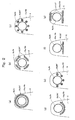
Figure 2(a) , the end face of thevalve plate 8, which is made of steel, contacting thesuction valves 10a is quenched without being melted by CO2 laser beam machining at portions near thesuction holes 8a, more specifically, continuous annular portions R1 around thesuction holes 8a. Then, the end face of thevalve plate 8 contacting thesuction valves 10a is ground to project the quenched portions from the remaining unquenched portions. In the same way, the end face of thevalve plate 8 contacting thedischarge valves 10b is quenched without being melted by CO2 laser beam machining at portions near thedischarge holes 8b, more specifically, continuous annular portions R1' around thedischarge holes 8b. Then, the end face of thevalve plate 8 contacting thedischarge valves 10b is ground to project the quenched portions from the remaining unquenched portions.
The continuous annular quenched portions may be constituted of many quenched dots made by a sharply focused thin laser beam or a quenched belt made by an unsharply focused thick laser beam.
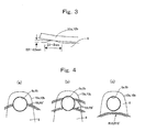
As shown inFigure 3 , the width of the projections is set at 0.1 mm to 2.0 mm and the height of the projections is set at 0.01 mm to 0.5 mm. The surface roughness of the projections is set at Rz10 or less. The hardness of the quenched portions is set at a level higher than that of the unquenched portions by HV100 or more. - In the variable displacement
swash plate compressor 1, therotation shaft 5 is rotated by a car engine not shown in the Figures, theswash plate 6 rotates synchronously with the rotation of therotation shaft 5, and thepistons 7 reciprocally move. Synchronously with the reciprocal movement of thepistons 7, coolant gas returns to the compressor from the evaporator of the car air conditioner, flows into the cylinder bores 2a through thesuction port 9a', thesuction chamber 9a, the suction holes 8a and thesuction valves 10a, becomes compressed in the cylinder bores 2a, and flows out of thecompressor 1 to the condenser of the car air conditioner through thedischarge holes 8b, thedischarge valves 10b, thedischarge chamber 9b and thedischarge port 9b'. - In the variable displacement
swash plate compressor 1, the end face of thevalve plate 8 contacting thesuction valves 10a is provided with projections at the portions near the suction holes 8a and the end face of thevalve plate 8 contacting thedischarge valves 10b is provided with projections at the portions near thedischarge holes 8b. Therefore, the sticking of thesuction valves 10a and thedischarge valves 10b on thevalve plate 8 caused by adhesion of lubricant oil dispersed in coolant gas is suppressed, delays in the opening actions of thesuction valves 10a and thedischarge valves 10b are prevented, and damage of thesuction valves 10a and thedischarge valves 10b and generation of noises caused by hard collisions between the tips of thesuction valves 10a and theconcaves 2b for restricting the lifts of thesuction valves 10a and hard collisions between thedischarge valves 10b and thevalve retainers 11 due to delays in the opening actions of thesuction valves 10a and thedischarge valves 10b are prevented.
In the variable displacementswash plate compressor 1, some portions of thevalve plate 8 are quenched by laser beam machining without being melted, and thevalve plate 8 is ground to form projections. Therefore, the productivity of projection formation is high.
If the width of the projections is too small, the projections wear easily. If the width of the projections is too large, the valves easily stick on the projections. Therefore, the width of the projections is desirably 0.1 to 2.0 mm.
If the height of the projections is too small, the projections wear easily. If the height of the projections is too large, the valves are liable to close incompletely. Therefore, the height of the projections is desirably 0.01 to 0.5 mm.
If the surface roughness of the projections is too large, gaps are formed between the projections and thesuction valves 10a and between the projections and thedischarge valves 10b to cause leakage of gas during the compressing process or sucking process, thereby decreasing compression efficiency. Therefore, the surface roughness of the projections is desirably less than that of the remaining flat unquenched portions and desirably Rz10 or less.
If the difference of hardness between the quenched portions and the unquenched portions is small, no projection can be made by grinding. Therefore, the hardness of the quenched portions is desirably higher than that of the unquenched portions by HV100 or more.
A CO2 laser is suitable for the quenching process as its output is large. - The portions near the suction holes to be quenched may be any one of intermittent annular portions R2, R3 shown in
Figures 2(b), 2(c) around thesuction holes 8a, continuous arc portions R4 shown inFigure 2(d) each thereof extending along a part of the periphery of eachsuction hole 8a, intermittent arc portions R5 shown inFigure 2(e) each thereof extending along a part of the periphery of eachsuction hole 8a, continuous single straight portions R6 or continuous multiple straight portions R7 shown inFigure 2(f) or 2(g) close to the peripheries of thesuction holes 8a, and intermittent single straight portions or intermittent multiple straight portions close to the peripheries of thesuction holes 8a.
The portions near the discharge holes to be quenched may be any one of intermittent annular portions R2', R3' shown inFigures 2(b), 2(c) around thedischarge holes 8b, continuous arc portions R4' shown inFigure 2(d) each thereof extending along a part of the periphery of eachdischarge hole 8b, intermittent arc portions R5' shown inFigure 2(e) each thereof extending along a part of the periphery of eachdischarge hole 8b, continuous single straight portions R6' or continuous multiple straight portions R7' shown inFigure 2(f) or 2(g) close to the peripheries of thedischarge holes 8b, and intermittent single straight portions or intermittent multiple straight portions close to the peripheries of thedischarge holes 8b. - As shown in
Figures 4(a) and 4(b) , it is possible to quench without melting the end face of thevalve plate 8 contacting thesuction valves 10a at an intermittent annular portion R8 or a plurality of intermittent annular portions R9 crossing all of the suction holes 8a and the end face of thevalve plate 8 contacting thedischarge valves 10b at an intermittent annular portion R8' or a plurality of intermittent annular portions R9' crossing all of the discharge holes 8b by CO2 laser beam machining, and grind the end face of thevalve plate 8 contacting thesuction valves 10a and the end face of thevalve plate 8 contacting thedischarge valves 10b to make the quenched portions project from the remaining unquenched portions.
As shown inFigure 4(c) , it is possible to quench without melting the end face of thevalve plate 8 contacting thesuction valves 10a at a continuous annular portion R10 close to all of the suction holes 8a and the end face of thevalve plate 8 contacting thedischarge valves 10b at a continuous annular portion R10' close to all of the discharge holes 8b by CO2 laser beam machining, and grind the end face of thevalve plate 8 contacting thesuction valves 10a and the end face of thevalve plate 8 contacting thedischarge valves 10b to make the quenched portions project from the remaining unquenched portions.
The annular quenched portions may be constituted of many quenched dots made by a sharply focused thin laser beam or a quenched belt made by an unsharply focused thick laser beam.
InFigures 4(a) and 4(c) , the laser beam machining can be finished by one pass, and inFigure 4(b) , the laser beam machining can be finished by a small number of passes. Thus, the productivity improves. - In the aforementioned embodiment, projections are formed on the end face of the
valve plate 8 contacting thesuction valve 10a and the end face of thevalve plate 8 contacting thedischarge valves 10b. The projections may be formed on either the end face of thevalve plate 8 contacting thesuction valve 10a or the end face of thevalve plate 8 contacting thedischarge valves 10b.
In the aforementioned embodiment, projections are formed on thevalve plate 8. The projections shown inFigures 2(a) to 2(g) may be formed on thesuction valves 10a and/or thedischarge valves 10b by the same process as in the case where the projections are formed on thevalve plate 8. - Instead of quenching by laser beam machining and grinding to form projections, it is possible to form projections by any one of a resin coat, plated metal coat, such as plated nickel coat, plated chromium coat, plated iron coat, etc., thermal sprayed material coat ,such as thermal sprayed metal coat, thermal sprayed ceramic coat, etc., sintered metal coat, such as sintered iron alloy coat, sintered copper alloy coat, etc., and ceramic coat, such as aluminum oxide coat, silicon oxide coat, etc. Productivity improves because forming projections by coating does not need machining so precise as forming projections by laser beam machining to melt and sputter.
A resin coat has an advantage in that it can be made easily. Among the various kinds of resin coats, fluoride resin coat repels oil to suppress generation of oil film. Therefore, fluoride resin coat is effective for preventing thesuction valves 10a and/or thedischarge valves 10b from sticking on thevalve plate 8.
Desirably, binder resin such as polyamideimide, epoxy, polyimide, polyamide, polyether ether ketone, etc. is mixed with the fluoride resin so as to enhance the adherence between the fluoride resin coat and the base material.
Forming of the resin coat by screen printing is good in recovery of coating material.
Desirably, pre-coat surface treatment such as chemical conversion treating, Tufftride processing, shot blasting, etc. is carried out on thesuction valves 10a, thedischarge valves 10b or thevalve plate 8 to enhance the adherence between the resin coat and thesuction valves 10a, thedischarge valves 10b or thevalve plate 8.
A sintered metal coat has an advantage in that it is superior in wear resistance and peeling resistance. When the sintered metal coat is porous, it absorbs oil to suppress generation of oil film. Therefore, a porous sintered metal coat is effective for preventing thesuction valves 10a and/or thedischarge valves 10b from sticking on thevalve plate 8. When a porous sintered metal coat is used for preventing thesuction valves 10a and/or thedischarge valves 10b from sticking on thevalve plate 8, the porous sintered metal coat may cover the entire end surface of thevalve plate 8 opposing thesuction valves 10a and/or thedischarge valves 10b.
When the porous sintered metal coat is impregnated with PTFE, i.e., polytetrafluoroethylene, it repels oil to suppress generation of oil film. Therefore, the porous sintered metal coat impregnated with PTFE is effective for preventing thesuction valves 10a and/or dischargevalves 10b from sticking on thevalve plate 8. - The present invention can be widely used in various kinds of reciprocating compressors including swash plate compressors, wobble plate compressors, etc.
-
-
Figure 1 is a sectional view of a variable displacement swash plate compressor to which the method for processing the contact portions between the valve plate and the suction valves and/or discharge valves of a reciprocating compressor in accordance with a preferred embodiment of the present invention is used. -
Figure 2 is a set of plan views of a contact portion between a valve plate and a suction valve and a set of plan views of a contact portion between a valve plate and a discharge valve for describing the method for processing in accordance with a preferred embodiment of the present invention. -
Figure 3 is a sectional view of a contact portion between a valve plate and a suction valve and a sectional view of a contact portion between a valve plate and a discharge valve for describing the method for processing in accordance with a preferred embodiment of the present invention. -
Figure 4 is a set of plan views of a contact portion between a valve plate and a suction valve and a set of plan views of a contact portion between a valve plate and a discharge valve for describing the method for processing in accordance with a preferred embodiment of the present invention. -
- 1
- Variable displacement swash plate compressor
- 2
- Cylinder block
- 2a
- Cylinder bore
- 2b
- Concave for restricting the lift
- 3
- Crank chamber
- 4
- Front head
- 5
- Rotation shaft
- 6
- Swash plate
- 7
- Piston
- 8
- Valve plate
- 8a
- Suction hole
- 8b
- Discharge hole
- 9
- Cylinder head
- 9a
- Suction chamber
- 9b
- Discharge chamber
- 10a
- Suction valve
- 10b
- Discharge valve
- 11
- Valve retainer
- R1, R1'
- Continuous annular portion
- R2,R3,R2',R3'
- Intermittent annular portion
- R4, R4'
- Continuous arc portion
- R5, R5'
- Intermittent arc portion
- R6,R7,R6',R7'
- Continuous straight portion
- R8,R9,R8',R9'
- Intermittent straight portion
- R10, R10'
- Continuous annular portion
Claims (27)
- A method for processing contact portions between a valve plate and a suction valve and/or discharge valve of a reciprocating compressor to prevent the suction valve and/or the discharge valve from sticking on the valve plate at the portions contacting the valve plate, wherein the compressor comprises a cylinder bore, a piston fitted in the cylinder bore to be capable of reciprocal movement, a valve plate provided with a suction hole and a discharge hole communicating with the cylinder bore, a strap-shaped suction valve for opening and closing the suction hole, a strap-shaped discharge valve for opening and closing the discharge hole, a suction chamber communicating with the cylinder bore through the suction hole and the suction valve, and a discharge chamber communicating with the cylinder bore through the discharge valve and the discharge hole, and wherein the method comprises the steps of quenching the portion of the end face of the valve plate contacting the suction valve near the suction hole and/or the portion of the end face of the valve plate contacting the discharge valve near the discharge hole by laser beam machining without melting them, and grinding the end face of the valve plate contacting the suction valve and/or the end face of the valve plate contacting the discharge valve to project the quenched portions from the remaining unquenched portions.
- A method for processing contact portions between a valve plate and a suction valve and/or discharge valve of a reciprocating compressor to prevent the suction valve and/or the discharge valve from sticking on the valve plate at the portions contacting the valve plate, wherein the compressor comprises a cylinder bore, a piston fitted in the cylinder bore to be capable of reciprocal movement, a valve plate provided with a suction hole and a discharge hole communicating with the cylinder bore, a strap-shaped suction valve for opening and closing the suction hole, a strap-shaped discharge valve for opening and closing the discharge hole, a suction chamber communicating with the cylinder bore through the suction hole and the suction valve, and a discharge chamber communicating with the cylinder bore through the discharge valve and the discharge hole, and wherein the method comprises the step of making any one of a resin coat, plated metal coat, thermal sprayed material coat, sintered metal coat and ceramic coat on the portion of the end face of the valve plate contacting the suction valve near the suction hole and/or the portion of the end face of the valve plate contacting the discharge valve near the discharge hole to project the coated portions from the remaining uncoated portions.
- A method for processing contact portions between a valve plate and a suction valve and/or discharge valve of a reciprocating compressor to prevent the suction valve and/or the discharge valve from sticking on the valve plate at the portions contacting the valve plate, wherein the compressor comprises a cylinder bore, a piston fitted in the cylinder bore to be capable of reciprocal movement, a valve plate provided with a suction hole and a discharge hole communicating with the cylinder bore, a strap-shaped suction valve for opening and closing the suction hole, a strap-shaped discharge valve for opening and closing the discharge hole, a suction chamber communicating with the cylinder bore through the suction hole and the suction valve, and a discharge chamber communicating with the cylinder bore through the discharge valve and the discharge hole, and wherein the method comprises the steps of quenching the portion of the end face of the suction valve contacting the valve plate opposing the portion of the valve plate near the suction hole and/or the portion of the end face of the discharge valve contacting the valve plate opposing the portion of the valve plate near the discharge hole by laser beam machining without melting them, and grinding the end face of the suction valve and/or the end face of the discharge valve to project the quenched portions from the remaining unquenched portions.
- A method for processing contact portions between a valve plate and a suction valve and/or discharge valve of a reciprocating compressor to prevent the suction valve and/or the discharge valve from sticking on the valve plate at the portions contacting the valve plate, wherein the compressor comprises a cylinder bore, a piston fitted in the cylinder bore to be capable of reciprocal movement, a valve plate provided with a suction hole and a discharge hole communicating with the cylinder bore, a strap-shaped suction valve for opening and closing the suction hole, a strap-shaped discharge valve for opening and closing the discharge hole, a suction chamber communicating with the cylinder bore through the suction hole and the suction valve, and a discharge chamber communicating with the cylinder bore through the discharge valve and the discharge hole, and wherein the method comprises the step of making any one of a resin coat, plated metal coat, thermal sprayed material coat, sintered metal coat and ceramic coat on the portion of the end face of the suction valve contacting the valve plate opposing the portion of the valve plate near the suction hole and/or the portion of the end face of the discharge valve contacting the valve plate opposing the portion of the valve plate near the discharge hole to project the coated portions from the remaining uncoated portions.
- A method for processing contact portions between a valve plate and a suction valve and/or discharge valve of a reciprocating compressor of any one of claims 1 to 4, wherein the portion near the suction hole is a continuous annular portion around the suction hole and the portion near the discharge hole is a continuous annular portion around the discharge holes.
- A method for processing contact portions between a valve plate and a suction valve and/or discharge valve of a reciprocating compressor of any one of claims 1 to 4, wherein the portion near the suction hole is an intermittent annular portion around the suction hole and the portion near the discharge hole is an intermittent annular portion around the discharge hole.
- A method for processing contact portions between a valve plate and a suction valve and/or discharge valve of a reciprocating compressor of any one of claims 1 to 4, wherein the portion near the suction hole is a continuous arc portion extending along a part of the periphery of the suction hole and the portion near the discharge hole is a continuous arc portion extending along a part of the periphery of the discharge hole.
- A method for processing contact portions between a valve plate and a suction valve and/or discharge valve of a reciprocating compressor of any one of claims 1 to 4, wherein the portion near the suction hole is an intermittent arc portion extending along a part of the periphery of the suction hole and the portion near the discharge hole is an intermittent arc portion extending along a part of the periphery of the discharge hole.
- A method for processing contact portions between a valve plate and a suction valve and/or discharge valve of a reciprocating compressor of any one of claims 1 to 4, wherein the portion near the suction hole is a continuous straight portion near the suction hole and the portion near the discharge hole is a continuous straight portion near the discharge hole.
- A method for processing contact portions between a valve plate and a suction valve and/or discharge valve of a reciprocating compressor of any one of claims 1 to 4, wherein the portion near the suction hole is an intermittent straight portion near the suction hole and the portion near the discharge hole is an intermittent straight portion near the discharge hole.
- A method for processing contact portions between a valve plate and a suction valve and/or discharge valve of a reciprocating compressor to prevent the suction valve and/or the discharge valve from sticking on the valve plate at the portions contacting the valve plate, wherein the compressor comprises cylinder bores, pistons fitted in the cylinder bores to be capable of reciprocal movement, a valve plate provided with suction holes and discharge holes communicating with the cylinder bores, strap-shaped suction valves for opening and closing the suction holes, strap-shaped discharge valves for opening and closing the discharge holes, a suction chamber communicating with the cylinder bores through the suction holes and the suction valves, and a discharge chamber communicating with the cylinder bores through the discharge valves and the discharge holes, and wherein the cylinder bores are circumferentially distanced from each other and located on the circumference of a first circle, the suction holes are circumferentially distanced from each other and located on the circumference of a second circle, and the discharge holes are circumferentially distanced from each other and located on the circumference of a third circle, and wherein the method comprises the steps of quenching the end face of the valve plate contacting the suction valves at an intermittent annular portion crossing all of the suction holes and/or the end face of the valve plate contacting the discharge valves at an intermittent annular portion crossing all of the discharge holes by laser beam machining without melting them, and grinding the end face of the valve plate contacting the suction valves and/or the end face of the valve plate contacting the discharge valves to project the quenched portions from the remaining unquenched portions.
- A method for processing contact portions between a valve plate and a suction valve and/or discharge valve of a reciprocating compressor to prevent the suction valve and/or the discharge valve from sticking on the valve plate at the portions contacting the valve plate, wherein the compressor comprises cylinder bores, pistons fitted in the cylinder bores to be capable of reciprocal movement, a valve plate provided with suction holes and discharge holes communicating with the cylinder bores, strap-shaped suction valves for opening and closing the suction holes, strap-shaped discharge valves for opening and closing the discharge holes, a suction chamber communicating with the cylinder bores through the suction holes and the suction valves, and a discharge chamber communicating with the cylinder bores through the discharge valves and the discharge holes, and wherein the cylinder bores are circumferentially distanced from each other and located on the circumference of a first circle, the suction holes are circumferentially distanced from each other and located on the circumference of a second circle, and the discharge holes are circumferentially distanced from each other and located on the circumference of a third circle, and wherein the method comprises the step of making any one of a resin coat, plated metal coat, thermal sprayed material coat, sintered metal coat and ceramic coat on the end face of the valve plate contacting the suction valves at an intermittent annular portion crossing all of the suction holes and/or the end face of the valve plate contacting the discharge valves at an intermittent annular portion crossing all of the discharge holes to project the coated portions from the remaining uncoated portions.
- A method for processing contact portions between a valve plate and a suction valve and/or discharge valve of a reciprocating compressor to prevent the suction valve and/or the discharge valve from sticking on the valve plate at the portions contacting the valve plate, wherein the compressor comprises cylinder bores, pistons fitted in the cylinder bores to be capable of reciprocal movement, a valve plate provided with suction holes and discharge holes communicating with the cylinder bores, strap-shaped suction valves for opening and closing the suction holes, strap-shaped discharge valves for opening and closing the discharge holes, a suction chamber communicating with the cylinder bores through the suction holes and the suction valves, and a discharge chamber communicating with the cylinder bores through the discharge valves and the discharge holes, and wherein the cylinder bores are circumferentially distanced from each other and located on the circumference of a first circle, the suction holes are circumferentially distanced from each other and located on the circumference of a second circle, and the discharge holes are circumferentially distanced from each other and located on the circumference of a third circle, and wherein the method comprises the steps of quenching the end face of the valve plate contacting the suction valves at a continuous annular portion close to all of the suction holes and/or the end face of the valve plate contacting the discharge valves at a continuous annular portion close to all of the discharge holes by laser beam machining without melting them, and grinding the end face of the valve plate contacting the suction valves and/or the end face of the valve plate contacting the discharge valves to project the quenched portions from the remaining unquenched portions.
- A method for processing contact portions between a valve plate and a suction valve and/or discharge valve of a reciprocating compressor to prevent the suction valve and/or the discharge valve from sticking on the valve plate at the portions contacting the valve plate, wherein the compressor comprises cylinder bores, pistons fitted in the cylinder bores to be capable of reciprocal movement, a valve plate provided with suction holes and discharge holes communicating with the cylinder bores, strap-shaped suction valves for opening and closing the suction holes, strap-shaped discharge valves for opening and closing the discharge holes, a suction chamber communicating with the cylinder bores through the suction holes and the suction valves, and a discharge chamber communicating with the cylinder bores through the discharge valves and the discharge holes, and wherein the cylinder bores are circumferentially distanced from each other and located on the circumference of a first circle, the suction holes are circumferentially distanced from each other and located on the circumference of a second circle, and the discharge holes are circumferentially distanced from each other and located on the circumference of a third circle, and wherein the method comprises the step of making any one of a resin coat, plated metal coat, thermal sprayed material coat, sintered metal coat and ceramic coat on the end face of the valve plate contacting the suction valves at a continuous annular portion close to all of the suction holes and/or the end face of the valve plate contacting the discharge valves at a continuous annular portion close to all of the discharge holes to project the coated portions from the remaining uncoated portions.
- A method for processing contact portions between a valve plate and a suction valve and/or discharge valve of a reciprocating compressor of any one of claims 1 to 14, wherein the width of the projections is 0.1 mm to 2.0 mm.
- A method for processing contact portions between a valve plate and a suction valve and/or discharge valve of a reciprocating compressor of any one of claims 1 to 15, wherein the height of the projections is 0.01 mm to 0.5 mm.
- A method for processing contact portions between a valve plate and a suction valve and/or discharge valve of a reciprocating compressor of any one of claims 1 to 16, wherein surface roughness of the projections is smaller than that of the remaining flat portions.
- A method for processing contact portions between a valve plate and a suction valve and/or discharge valve of a reciprocating compressor of claim 17, wherein surface roughness of the projections is Rz10 or less.
- A method for processing contact portions between a valve plate and a suction valve and/or discharge valve of a reciprocating compressor of any one of claims 1, 3, 11 and 13, wherein hardness of the quenched portions is higher than that of the unquenched portions by HV100 or more.
- A method for processing contact portions between a valve plate and a suction valve and/or discharge valve of a reciprocating compressor of any one of claims 1, 3, 11, 13 and 19, wherein the laser beam machining is CO2 laser beam machining.
- A method for processing contact portions between a valve plate and a suction valve and/or discharge valve of a reciprocating compressor of any one of claims 2, 4, 12 and 14, wherein the resin coat is a fluoride resin coat.
- A method for processing contact portions between a valve plate and a suction valve and/or discharge valve of a reciprocating compressor of claim 21, wherein the binder of the resin coating is at least one selected from the group consisting of polyamideimide, epoxy, polyimide, polyamide, and polyether ether ketone.
- A method for processing contact portions between a valve plate and a suction valve and/or discharge valve of a reciprocating compressor of any one of claims 2, 4, 12, 14, 21 and 22, wherein the resin coat is made by screen printing.
- A method for processing contact portions between a valve plate and a suction valve and/or discharge valve of a reciprocating compressor of any one of claims 2, 4, 12, 14, 21, 22 and 23, further comprising the step of any one of chemical conversion treating, Tufftride processing and shot blasting the end faces to be resin coated before the step of making resin coat.
- A method for processing contact portions between a valve plate and a suction valve and/or discharge valve of a reciprocating compressor of any one of claims 2, 4, 12 and 14, wherein the sintered metal coat is porous coat.
- A method for processing contact portions between a valve plate and a suction valve and/or discharge valve of a reciprocating compressor of claim 25, further comprising the step of impregnating the sintered metal coat with PTFE, i.e., polytetrafluoroethylene.
- A reciprocating compressor, wherein the contact portions between a valve plate and a suction valve and/or discharge valve are processed by the method of any one of claims 1 to 26.
Applications Claiming Priority (1)
| Application Number | Priority Date | Filing Date | Title |
|---|---|---|---|
| PCT/JP2009/051902 WO2010089865A1 (en) | 2009-02-04 | 2009-02-04 | Method of processing contact portions between valve plate and suction valve and/or discharge valve of reciprocating compressor, and reciprocating compressor |
Publications (2)
| Publication Number | Publication Date |
|---|---|
| EP2395244A1 true EP2395244A1 (en) | 2011-12-14 |
| EP2395244A4 EP2395244A4 (en) | 2014-01-08 |
Family
ID=42541787
Family Applications (1)
| Application Number | Title | Priority Date | Filing Date |
|---|---|---|---|
| EP09839642.7A Withdrawn EP2395244A4 (en) | 2009-02-04 | 2009-02-04 | Method of processing contact portions between valve plate and suction valve and/or discharge valve of reciprocating compressor, and reciprocating compressor |
Country Status (5)
| Country | Link |
|---|---|
| US (1) | US20110300009A1 (en) |
| EP (1) | EP2395244A4 (en) |
| KR (1) | KR101283437B1 (en) |
| CN (1) | CN102301138A (en) |
| WO (1) | WO2010089865A1 (en) |
Cited By (1)
| Publication number | Priority date | Publication date | Assignee | Title |
|---|---|---|---|---|
| EP3159540A4 (en) * | 2014-06-19 | 2017-10-18 | Panasonic Corporation | Refrigerant compressor and refrigeration appliance using same |
Families Citing this family (4)
| Publication number | Priority date | Publication date | Assignee | Title |
|---|---|---|---|---|
| DE112009001704B4 (en) * | 2008-08-21 | 2024-08-01 | Hanon Systems Efp Deutschland Gmbh | Reciprocating piston engine |
| KR101408057B1 (en) * | 2010-01-28 | 2014-06-17 | 가부시키가이샤 도요다 지도숏키 | Compressor |
| CN105889050B (en) * | 2015-04-14 | 2019-02-19 | 康茨(上海)压缩机技术服务有限公司 | One kind intelligently opening and closing control method for piston compressor air valve |
| JP7200535B2 (en) * | 2018-08-17 | 2023-01-10 | セイコーエプソン株式会社 | Structure, Diaphragm Compressor, Cooling Machine, Projector, and Method for Manufacturing Structure |
Family Cites Families (17)
| Publication number | Priority date | Publication date | Assignee | Title |
|---|---|---|---|---|
| JPS52147302A (en) * | 1976-06-02 | 1977-12-07 | Iwata Air Compressor Mfg | Suction valves for reciprocating compressors |
| JPS60237186A (en) * | 1984-05-09 | 1985-11-26 | Toshiba Corp | Production method of valve plate of closed type compressor |
| JPS6279985U (en) * | 1985-11-07 | 1987-05-22 | ||
| JPS63147577U (en) * | 1987-03-18 | 1988-09-28 | ||
| JPH0335275U (en) * | 1989-08-09 | 1991-04-05 | ||
| JP2953028B2 (en) * | 1990-01-16 | 1999-09-27 | 株式会社豊田自動織機製作所 | Compressor discharge valve mechanism |
| US5228468A (en) * | 1992-06-04 | 1993-07-20 | Ingersoll-Rand Company | Valve and valve seat for flat valve and method of making same |
| JPH07174071A (en) * | 1993-08-10 | 1995-07-11 | Sanden Corp | Discharge mechanism for compressor |
| KR100203975B1 (en) * | 1995-10-26 | 1999-06-15 | 이소가이 치세이 | Cam Plate Variable Capacity Compressor |
| JP2001099066A (en) | 1999-09-28 | 2001-04-10 | Sanyo Electric Co Ltd | Refrigerant compressor |
| CN100422553C (en) * | 2003-09-02 | 2008-10-01 | 株式会社丰田自动织机 | Swash plate type compressor |
| JP4631266B2 (en) * | 2003-10-23 | 2011-02-16 | 大豊工業株式会社 | Cylinder head gasket |
| JP2005180660A (en) * | 2003-12-22 | 2005-07-07 | Uchiyama Mfg Corp | Cylinder head gasket |
| JP2007064196A (en) | 2005-08-05 | 2007-03-15 | Valeo Thermal Systems Japan Corp | Method for processing valve mechanism constituting member |
| JP2008002387A (en) * | 2006-06-23 | 2008-01-10 | Toshiba Kyaria Kk | Refrigerant compressor and refrigeration cycle apparatus using the same |
| US8118567B2 (en) * | 2006-12-15 | 2012-02-21 | Kabushiki Kaisha Kawasaki Precision Machinery | Swash plate type piston pump motor |
| JP2008274886A (en) * | 2007-05-02 | 2008-11-13 | Daikin Ind Ltd | Discharge valve |
-
2009
- 2009-02-04 KR KR1020117018548A patent/KR101283437B1/en not_active Expired - Fee Related
- 2009-02-04 EP EP09839642.7A patent/EP2395244A4/en not_active Withdrawn
- 2009-02-04 WO PCT/JP2009/051902 patent/WO2010089865A1/en not_active Ceased
- 2009-02-04 US US13/148,033 patent/US20110300009A1/en not_active Abandoned
- 2009-02-04 CN CN2009801559496A patent/CN102301138A/en active Pending
Cited By (1)
| Publication number | Priority date | Publication date | Assignee | Title |
|---|---|---|---|---|
| EP3159540A4 (en) * | 2014-06-19 | 2017-10-18 | Panasonic Corporation | Refrigerant compressor and refrigeration appliance using same |
Also Published As
| Publication number | Publication date |
|---|---|
| CN102301138A (en) | 2011-12-28 |
| KR20110096181A (en) | 2011-08-29 |
| US20110300009A1 (en) | 2011-12-08 |
| WO2010089865A1 (en) | 2010-08-12 |
| KR101283437B1 (en) | 2013-07-08 |
| EP2395244A4 (en) | 2014-01-08 |
Similar Documents
| Publication | Publication Date | Title |
|---|---|---|
| JP3918516B2 (en) | Swash plate compressor | |
| JP3439949B2 (en) | Hard coating material, sliding member coated therewith, and method of manufacturing the same | |
| US20110300009A1 (en) | Method of Processing Contact Portions between Valve Plate and Suction Valve and/or Discharge Valve of Reciprocating Compressor, and Reciprocating Compressor | |
| EP1281863A2 (en) | Compressor coating | |
| EP1985856A1 (en) | Compressor swash plate and method of manufacturing the same | |
| KR20020046211A (en) | Compressor and sliding member thereof | |
| WO2015041215A1 (en) | Combination of cylinder bore and piston ring | |
| EP3051157A1 (en) | Sliding member | |
| US20030096134A1 (en) | Sliding member for compressor | |
| US6926779B1 (en) | Lead-free copper-based coatings with bismuth for swashplate compressors | |
| JP2003042061A (en) | Swash plate compressor | |
| US6435047B1 (en) | Shoe for swash-plate type compressor | |
| JP2002317759A (en) | Shoe for swash plate-type compressor and swash plate- type compressor having the same | |
| JP5101879B2 (en) | Sliding structure | |
| KR100888016B1 (en) | Sliding device | |
| US20030121412A1 (en) | Shoe for swash plate type compressor and swash plate type compressor equipped with the shoe | |
| JP2002332959A (en) | Spherical crown-shaped shoe and swash plate-type compressor having the same | |
| JP2020528526A (en) | A piston ring with a short peened familiar layer, and a method for manufacturing the piston ring. | |
| JP2009052538A (en) | Processing method for contact section between valve plate and suction valve and/or discharge valve of reciprocating compressor and reciprocating compressor | |
| EP1079110A2 (en) | Coating process for a swash plate of a compressor | |
| JP2003183685A (en) | Sliding member | |
| CN118715368A (en) | Hydraulic rotating machines | |
| JP3642917B2 (en) | Rigid coating material, sliding member coated with the same, and manufacturing method thereof | |
| JP5601990B2 (en) | Swash plate compressor and swash plate surface treatment method for swash plate compressor | |
| JP2004300926A (en) | Swash plate compressor |
Legal Events
| Date | Code | Title | Description |
|---|---|---|---|
| PUAI | Public reference made under article 153(3) epc to a published international application that has entered the european phase |
Free format text: ORIGINAL CODE: 0009012 |
|
| 17P | Request for examination filed |
Effective date: 20110901 |
|
| AK | Designated contracting states |
Kind code of ref document: A1 Designated state(s): AT BE BG CH CY CZ DE DK EE ES FI FR GB GR HR HU IE IS IT LI LT LU LV MC MK MT NL NO PL PT RO SE SI SK TR |
|
| DAX | Request for extension of the european patent (deleted) | ||
| A4 | Supplementary search report drawn up and despatched |
Effective date: 20131206 |
|
| RIC1 | Information provided on ipc code assigned before grant |
Ipc: F04B 27/08 20060101ALI20131202BHEP Ipc: F04B 39/10 20060101AFI20131202BHEP |
|
| STAA | Information on the status of an ep patent application or granted ep patent |
Free format text: STATUS: THE APPLICATION HAS BEEN WITHDRAWN |
|
| 18W | Application withdrawn |
Effective date: 20140110 |