EP2394788A1 - Abrasive blast contour machining to remove surface and near-surface crack initiation - Google Patents
Abrasive blast contour machining to remove surface and near-surface crack initiation Download PDFInfo
- Publication number
- EP2394788A1 EP2394788A1 EP11167875A EP11167875A EP2394788A1 EP 2394788 A1 EP2394788 A1 EP 2394788A1 EP 11167875 A EP11167875 A EP 11167875A EP 11167875 A EP11167875 A EP 11167875A EP 2394788 A1 EP2394788 A1 EP 2394788A1
- Authority
- EP
- European Patent Office
- Prior art keywords
- recited
- nozzle
- crack initiation
- erosion rate
- axis machine
- Prior art date
- Legal status (The legal status is an assumption and is not a legal conclusion. Google has not performed a legal analysis and makes no representation as to the accuracy of the status listed.)
- Withdrawn
Links
Images


Classifications
-
- B—PERFORMING OPERATIONS; TRANSPORTING
- B24—GRINDING; POLISHING
- B24C—ABRASIVE OR RELATED BLASTING WITH PARTICULATE MATERIAL
- B24C1/00—Methods for use of abrasive blasting for producing particular effects; Use of auxiliary equipment in connection with such methods
- B24C1/08—Methods for use of abrasive blasting for producing particular effects; Use of auxiliary equipment in connection with such methods for polishing surfaces, e.g. smoothing a surface by making use of liquid-borne abrasives
Definitions
- the present disclosure relates to a surfacing technique, and more particularly to an abrasive machining technique that eliminates crack initiation sites.
- a multi-axis machine includes a controller operable to control a nozzle which ejects a particulate material, relative to a part surface to maintain a compound angle and predetermined stand off distance to remove surface and near-surface crack initiation sites.
- a method of surface machining according to an exemplary aspect of the present disclosure includes removing surface and near-surface crack initiation sites with a particulate matter.
- the surface machining technique disclosed herein utilizes the multi-axis motion with variable velocity control through the positioning apparatus 26 to assure a uniform erosion rate is achieved upon the desired surfaces S of the workpiece W.
- the control 28 locates the nozzle 24 relative to the surface S of the workpiece W at a constant compound angle and predetermined stand off distance which is consistently maintained as the nozzle 24 traverses the various surfaces S1-Sn ( Figures 2 and 3 ) of the workpiece W.
- the compound angle generally includes an alpha ( ⁇ ) and beta ( ⁇ ) component which may or not may not remain same relative to each surface S1-Sn of the workpiece W ( Figure 3 ) depending on desired amount of erosion at each surface of the workpiece.
- the particulate matter erodes the material to produce a surface free of the damaged layer caused by previous conventional machining operations. That is, the previous conventional machining operations result in a damaged layer with surface and near-surface crack initiation sites.
- the surface machining technique disclosed herein eliminates this damaged layer to improve the fatigue life up to ten times compared to the life of conventionally machined alloy 718.
- the surface machining technique uniformly removes high amounts of material as compared to conventional abrasive blasting processes.
- the disclosed surface machining technique uses specific media, machining angles and gun distances to achieve tightly controlled and relatively significant material removal rates more typical of a machining processes.
- Material removal typical of the surface machining technique in one non-limiting embodiment disclosed herein is 0.002- 0.003" (0.05-0.07 mm) of material removal compared to a conventional abrasive surface treatment/cleaning process that removes only approximately 0.0005" (0.001 mm) of surface contaminants with little regard to final product size.
- the material removal rate disclosed herein is for alloy 718 and may be varied dependant on the surface damage experienced by other alloys. That is, use of different grit sizes and materials may be utilized to remove surface damage of any type.
- the surface machining technique disclosed herein has been found to remove both hard surface material conditions and slightly distorted surface structure with equal efficiency on several high strength aerospace alloys, with no compromise in size control.
- the surface machining technique disclosed herein provides for a competitive advantage over those that use a typically-processed alloy 718 part.
- Possible components that could necessitate enhanced LCF life are: different flight envelopes which increase stresses or temperatures, requirements for larger surface damage, i.e., handling damage, allowances in the field, or reverse engineering a material in a gas turbine engine program with lower life margins.
Landscapes
- Engineering & Computer Science (AREA)
- Mechanical Engineering (AREA)
- Perforating, Stamping-Out Or Severing By Means Other Than Cutting (AREA)
Abstract
A multi-axis machine (20) includes a controller (28) operable to control a nozzle (24) which ejects a particulate material relative to a part surface (S) to maintain a compound angle and predetermined stand off distance to remove surface and near-surface crack initiation sites.
Description
- The present disclosure relates to a surfacing technique, and more particularly to an abrasive machining technique that eliminates crack initiation sites.
- Conventional machining of alloy 718 material may introduce damage to surface and near surface carbide particles inherent to the 718 alloy. These surface carbide particles are cracked by interaction of the machining tools and the brittle carbides. Under fatigue loading conditions, these carbides may serve as preferential locations for crack initiation which may limit the useful life of the material.
- A multi-axis machine according to an exemplary aspect of the present disclosure includes a controller operable to control a nozzle which ejects a particulate material, relative to a part surface to maintain a compound angle and predetermined stand off distance to remove surface and near-surface crack initiation sites.
- A method of surface machining according to an exemplary aspect of the present disclosure includes removing surface and near-surface crack initiation sites with a particulate matter.
- Various features will become apparent to those skilled in the art from the following detailed description of the disclosed non-limiting embodiment. The drawings that accompany the detailed description can be briefly described as follows:
-
Figure 1 is a general schematic view of a multi-axis system for use with the present disclosure; -
Figure 2 is a schematic view of a nozzle position with respect to a workpiece to illustrate a first component of the compound angle; -
Figure 3 is a sectional view of the workpiece inFigure 2 taken along line 3-3 to illustrate a second component of the compound angle; and -
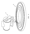
Figure 4 is a perspective view of a nozzle position with respect to an example workpiece. -
Figure 1 schematically illustrates amulti-axis system 20. Thesystem 20 generally includes aparticulate matter supply 22, anozzle 24 to dispense the particulate matter, apositioning apparatus 26 and acontrol 28. Thenozzle 24 is located relative a workpiece W by thepositioning apparatus 26 under direction of thecontrol 28. The particulate matter supply 22 in the disclosed non-limiting embodiment supplies a 500 grit aluminum oxide powder through thenozzle 24 which may be a 5/16" (7.9375 mm) diameter nozzle. Thepositioning apparatus 26 provides multi-axis motion with variable velocity control to consistently position thenozzle 24 relative to each surfaces S of the workpiece W under direction of thecontrol 28. Thecontrol 28 is utilized to implement the operational functionality of thepositioning apparatus 26 to direct thenozzle 24 relative to the workpiece W. In terms of hardware architecture, the computing device can include a processor, memory, and one or more input and/or output (I/O) device interface(s) that are communicatively coupled via a local interface. It should be understood that thesystem 20 is schematically depicted herein with conventional systems, however, various other configurations may alternatively or additionally provided to effectuate the surface machining technique disclosed herein. - The surface machining technique disclosed herein utilizes the multi-axis motion with variable velocity control through the
positioning apparatus 26 to assure a uniform erosion rate is achieved upon the desired surfaces S of the workpiece W. Thecontrol 28 locates thenozzle 24 relative to the surface S of the workpiece W at a constant compound angle and predetermined stand off distance which is consistently maintained as thenozzle 24 traverses the various surfaces S1-Sn (Figures 2 and 3 ) of the workpiece W. The compound angle generally includes an alpha (α) and beta (β) component which may or not may not remain same relative to each surface S1-Sn of the workpiece W (Figure 3 ) depending on desired amount of erosion at each surface of the workpiece. - As the particulate matter strikes the workpiece W, the particulate matter erodes the material to produce a surface free of the damaged layer caused by previous conventional machining operations. That is, the previous conventional machining operations result in a damaged layer with surface and near-surface crack initiation sites. The surface machining technique disclosed herein eliminates this damaged layer to improve the fatigue life up to ten times compared to the life of conventionally machined alloy 718.
- The surface machining technique uniformly removes high amounts of material as compared to conventional abrasive blasting processes. In other words, rather than a surface treatment/cleaning process typical of conventional abrasive blast processing, the disclosed surface machining technique uses specific media, machining angles and gun distances to achieve tightly controlled and relatively significant material removal rates more typical of a machining processes. Material removal typical of the surface machining technique in one non-limiting embodiment disclosed herein is 0.002- 0.003" (0.05-0.07 mm) of material removal compared to a conventional abrasive surface treatment/cleaning process that removes only approximately 0.0005" (0.001 mm) of surface contaminants with little regard to final product size.
- The material removal rate disclosed herein is for alloy 718 and may be varied dependant on the surface damage experienced by other alloys. That is, use of different grit sizes and materials may be utilized to remove surface damage of any type. The surface machining technique disclosed herein has been found to remove both hard surface material conditions and slightly distorted surface structure with equal efficiency on several high strength aerospace alloys, with no compromise in size control.
- Since the surface machining technique enhances Low Cycle Fatigue (LCF) life, the surface machining technique disclosed herein provides for a competitive advantage over those that use a typically-processed alloy 718 part. Possible components that could necessitate enhanced LCF life are: different flight envelopes which increase stresses or temperatures, requirements for larger surface damage, i.e., handling damage, allowances in the field, or reverse engineering a material in a gas turbine engine program with lower life margins.
- It should be understood that like reference numerals identify corresponding or similar elements throughout the several drawings. It should also be understood that although a particular component arrangement is disclosed in the illustrated embodiment, other arrangements will benefit herefrom.
- Although particular step sequences are shown, described, and claimed, it should be understood that steps may be performed in any order, separated or combined unless otherwise indicated and will still benefit from the present disclosure.
- The foregoing description is exemplary rather than defined by the limitations within. Various non-limiting embodiments are disclosed herein, however, one of ordinary skill in the art would recognize that various modifications and variations in light of the above teachings will fall within the scope of the appended claims. It is therefore to be understood that within the scope of the appended claims, the disclosure may be practiced other than as specifically described. For that reason the appended claims should be studied to determine true scope and content.
Claims (10)
- A multi-axis machine comprising:a nozzle (24) operable to eject a particulate matter; anda controller (28) operable to control said nozzle (24) relative to a part surface (S) to maintain a compound angle and predetermined stand off distance to remove surface and near-surface crack initiation sites.
- The multi-axis machine as recited in claim 1, wherein said nozzle (24) directs an aluminum oxide powder at a constant pressure.
- The multi-axis machine as recited in claim 1 or 2, wherein said compound angle is never perpendicular to a workpiece surface.
- The multi-axis machine as recited in claim 1, 2 or 3, further comprising maintaining a uniform erosion rate across all features of a workpiece surface (S).
- The multi-axis machine as recited in claim 4, wherein said uniform erosion rate removes at least 0.002 inches (5.1µm) of material.
- A method of surface machining comprising:removing surface and near-surface crack initiation sites with a particulate matter.
- The method as recited in claim 6, wherein said removing comprises:maintaining a compound angle and predetermined stand off distance between a nozzle (24) which ejects the particulate matter and a workpiece surface (S).
- The method as recited in claim 6 or 7, wherein said removing comprises:maintaining a uniform erosion rate across all features of a workpiece surface (S).
- The method as recited in claim 8, wherein the uniform erosion rate removes at least 0.002 (5.1µm) inches of material.
- The method as recited in claim 8 or 9, wherein maintaining the uniform erosion rate comprises:moving the nozzle (24) through a multi-axis motion machine with variable velocity control.
Applications Claiming Priority (2)
| Application Number | Priority Date | Filing Date | Title |
|---|---|---|---|
| US35248310P | 2010-06-08 | 2010-06-08 | |
| US13/022,814 US20110300779A1 (en) | 2010-06-08 | 2011-02-08 | Abrasive blast contour machining to remove surface and near-surface crack initiation |
Publications (1)
| Publication Number | Publication Date |
|---|---|
| EP2394788A1 true EP2394788A1 (en) | 2011-12-14 |
Family
ID=44587633
Family Applications (1)
| Application Number | Title | Priority Date | Filing Date |
|---|---|---|---|
| EP11167875A Withdrawn EP2394788A1 (en) | 2010-06-08 | 2011-05-27 | Abrasive blast contour machining to remove surface and near-surface crack initiation |
Country Status (2)
| Country | Link |
|---|---|
| US (1) | US20110300779A1 (en) |
| EP (1) | EP2394788A1 (en) |
Families Citing this family (2)
| Publication number | Priority date | Publication date | Assignee | Title |
|---|---|---|---|---|
| US9932988B2 (en) | 2013-02-15 | 2018-04-03 | United Technologies Corporation | Bushing arranged between a body and a shaft, and connected to the shaft |
| US10024162B2 (en) * | 2013-03-14 | 2018-07-17 | United Technologies Corporation | Turbine disk fatigue rejuvenation |
Citations (3)
| Publication number | Priority date | Publication date | Assignee | Title |
|---|---|---|---|---|
| WO2001015866A1 (en) * | 1999-09-01 | 2001-03-08 | Siemens Aktiengesellschaft | Method and device for treating the surface of a part |
| US20010047675A1 (en) * | 2000-05-11 | 2001-12-06 | Arola Dwayne D. | Method and apparatus for abrasive water jet peening surface treatment |
| WO2005018878A2 (en) * | 2003-08-26 | 2005-03-03 | Ormond, Llc | Cnc abrasive fluid-jet m illing |
Family Cites Families (3)
| Publication number | Priority date | Publication date | Assignee | Title |
|---|---|---|---|---|
| ATE528107T1 (en) * | 2000-12-21 | 2011-10-15 | Qed Technologies Int Inc | BEAM SURFACE PROCESSING OF A SUBSTRATE SURFACE |
| US7455573B2 (en) * | 2006-09-06 | 2008-11-25 | Lightmachinery Inc. | Fluid jet polishing with constant pressure pump |
| US8172163B2 (en) * | 2010-03-22 | 2012-05-08 | King Abdulaziz University | System and method for producing nanomaterials |
-
2011
- 2011-02-08 US US13/022,814 patent/US20110300779A1/en not_active Abandoned
- 2011-05-27 EP EP11167875A patent/EP2394788A1/en not_active Withdrawn
Patent Citations (3)
| Publication number | Priority date | Publication date | Assignee | Title |
|---|---|---|---|---|
| WO2001015866A1 (en) * | 1999-09-01 | 2001-03-08 | Siemens Aktiengesellschaft | Method and device for treating the surface of a part |
| US20010047675A1 (en) * | 2000-05-11 | 2001-12-06 | Arola Dwayne D. | Method and apparatus for abrasive water jet peening surface treatment |
| WO2005018878A2 (en) * | 2003-08-26 | 2005-03-03 | Ormond, Llc | Cnc abrasive fluid-jet m illing |
Also Published As
| Publication number | Publication date |
|---|---|
| US20110300779A1 (en) | 2011-12-08 |
Similar Documents
| Publication | Publication Date | Title |
|---|---|---|
| EP1941968A2 (en) | Method and apparatus for increasing fatigue notch capability of airfoils | |
| Uhlmann et al. | Machining of carbon fibre reinforced plastics | |
| US6905396B1 (en) | Method of removing a coating from a substrate | |
| CN107835731B (en) | Method for cutting fiber reinforced polymer composite workpiece by pure water jet | |
| JP5782338B2 (en) | End processing method for plate material and blasting apparatus | |
| US20020098776A1 (en) | Method and device for treating the surface of a part | |
| EP3245007B1 (en) | Cold spray method to repair or in certain cases strengthen metals | |
| EP2902530B1 (en) | Method for applying a coating to a substrate | |
| EP1688211A2 (en) | Plasma arc weld repair of high nickel metal alloys | |
| EP1674594A1 (en) | Blade platform restoration using cold spray | |
| US20060121183A1 (en) | Superalloy repair using cold spray | |
| CN109338271A (en) | A kind of aero-engine titanium alloy component seam allowance repairing sizes method | |
| CN101972980A (en) | Equipment for automatically strengthening and grinding surfaces of machines | |
| Adibi et al. | Investigation on using high-pressure fluid jet in grinding process for less wheel loaded areas | |
| EP1634976A1 (en) | Method for applying abrasive and environment-resistant coatings onto turbine components | |
| CN103009024A (en) | Components with cooling channels and methods of manufacture | |
| EP3056312B1 (en) | Ceramic coating polishing method | |
| CA2879713A1 (en) | Method for applying a coating to a substrate | |
| EP2394788A1 (en) | Abrasive blast contour machining to remove surface and near-surface crack initiation | |
| JP6254820B2 (en) | Component with microcooled patterning coating layer and method of manufacturing | |
| US7950121B2 (en) | Method for rounding the edges of parts | |
| EP2287353A1 (en) | Method for Repairing a Workpiece | |
| CN101737352A (en) | Surface wear-resisting layer of gas turbine compressor blade and blade root and manufacturing method thereof | |
| CN110877295B (en) | Method for processing blade disc wet shot blasting and blade disc | |
| JP4252556B2 (en) | How to remove hard coating |
Legal Events
| Date | Code | Title | Description |
|---|---|---|---|
| AK | Designated contracting states |
Kind code of ref document: A1 Designated state(s): AL AT BE BG CH CY CZ DE DK EE ES FI FR GB GR HR HU IE IS IT LI LT LU LV MC MK MT NL NO PL PT RO RS SE SI SK SM TR |
|
| AX | Request for extension of the european patent |
Extension state: BA ME |
|
| PUAI | Public reference made under article 153(3) epc to a published international application that has entered the european phase |
Free format text: ORIGINAL CODE: 0009012 |
|
| 17P | Request for examination filed |
Effective date: 20120611 |
|
| 17Q | First examination report despatched |
Effective date: 20130927 |
|
| STAA | Information on the status of an ep patent application or granted ep patent |
Free format text: STATUS: THE APPLICATION IS DEEMED TO BE WITHDRAWN |
|
| 18D | Application deemed to be withdrawn |
Effective date: 20141014 |