EP2394769B1 - Band saw machine - Google Patents
Band saw machine Download PDFInfo
- Publication number
- EP2394769B1 EP2394769B1 EP20110168894 EP11168894A EP2394769B1 EP 2394769 B1 EP2394769 B1 EP 2394769B1 EP 20110168894 EP20110168894 EP 20110168894 EP 11168894 A EP11168894 A EP 11168894A EP 2394769 B1 EP2394769 B1 EP 2394769B1
- Authority
- EP
- European Patent Office
- Prior art keywords
- band
- cutting
- cutting unit
- base
- cut
- Prior art date
- Legal status (The legal status is an assumption and is not a legal conclusion. Google has not performed a legal analysis and makes no representation as to the accuracy of the status listed.)
- Active
Links
Images


Classifications
-
- B—PERFORMING OPERATIONS; TRANSPORTING
- B23—MACHINE TOOLS; METAL-WORKING NOT OTHERWISE PROVIDED FOR
- B23D—PLANING; SLOTTING; SHEARING; BROACHING; SAWING; FILING; SCRAPING; LIKE OPERATIONS FOR WORKING METAL BY REMOVING MATERIAL, NOT OTHERWISE PROVIDED FOR
- B23D53/00—Machines or devices for sawing with strap saw-blades which are effectively endless in use, e.g. for contour cutting
- B23D53/04—Machines or devices for sawing with strap saw-blades which are effectively endless in use, e.g. for contour cutting with the wheels carrying the strap mounted shiftably or swingingly, i.e. during sawing, other than merely for adjustment
- B23D53/045—Machines or devices for sawing with strap saw-blades which are effectively endless in use, e.g. for contour cutting with the wheels carrying the strap mounted shiftably or swingingly, i.e. during sawing, other than merely for adjustment with pivotedly mounted head carrying the saw wheels
Definitions
- This invention relates to a band saw machine.
- the preamble of claim 1 is based on WO 2009/128628 .
- this invention relates to a band saw machine of the type used for cutting metal.
- Band saw machines are known to be alternative to circular blade cutters which have the disadvantage of having an upper limit to cutting depth which depends on the radius of the blade itself.
- Prior art band saws comprise a horizontal base to which a frame is hinged, by means of a suitable support, the frame being equipped with two pulleys: a drive pulley and an idle pulley.
- the base also mounts a vice for clamping the part to be cut.
- the frame is also rotatable as one with its support so that the part can be cut at different angles - usually from 90° to 45° but even as far as 30° and further - with reference to the longitudinal direction of extension of the part itself, usually in bar form.
- cutting capacity is meant the maximum dimensions of the parts (bars of quadrangular, round or similar shapes) which can be cut.
- This invention therefore has for an object to increase the cutting capacity of band saw machines without increasing machine footprint.
- Another object of the invention is to provide a band saw machine which has a good cutting capacity and which is at once simple and inexpensive to make and practical to use.
- the reference numeral 1 denotes in its entirety a band saw machine made according to this invention.
- the band saw machine 1 comprises a base 2 constructed in such a way that it can be securely positioned on the floor or on a work bench, and a cutting unit 3 connected to the base 2 by means of a mounting element 4.
- the base 2 has a top face 2a that defines a plane P.
- the mounting element 4 of the cutting unit 3 is movable relative to the base 2 in the plane P to move the cutting unit 3 in such a way as to cut a part 10 at different angles.
- the cutting unit 3 comprises an endless toothed saw band 5 which is movable on a respective frame 6.
- the saw band 5 is trained in a loop around respective pulleys not shown in the drawings and has at least one cutting portion consisting of a set of teeth (not illustrated) whose cutting edge is inclined, as is customary, by a predetermined angle to the feed direction of the saw band 5 itself.
- a clamping element 7 mounted on the base 2 is a clamping element 7, for example a vice, for locking a part 10 to be cut, the latter being drawn with dashed lines in Figure 1 .
- the vice 7 has a fixed jaw 7a, mounted squarely relative to a bottom 7b integral with it, and a movable jaw 7c.
- the bottom 7b defines a supporting surface for the part 10 to be cut.
- the fixed jaw 7a With its locating wall for the part 10, the fixed jaw 7a defines a plane P1.
- the movable jaw 7c is adapted to be moved, in known manner, towards the fixed jaw 7a by means of a threaded rod 7d, so that the part to be cut is clamped between the two jaws.
- part 10 to be cut is supported directly by the base 2. That is to say there are no clamping elements like the vice 7.
- the base 2 supports the part 10 indirectly.
- the frame 6 of the cutting unit 3 is rotatably supported by the mounting element 4 in such a way as to rotate about a horizontal axis A1 and so that the cutting unit 3 can move between a first, lowered position where the rotating band 5 works on the part 10 to be cut, and a second, raised position (illustrated in Figure 1 ) where the band 5 is disengaged from the part 10 to be cut.
- the machine 1 further comprises an actuating lever 8 connected to one end of the frame 3, the lever 8 being usable by an operator to move the cutting unit 3 between the above mentioned first and second positions.
- actuating lever 8 mounted advantageously on the lever 8 is a pushbutton, not illustrated, for starting the machine 1.
- the rotating band 5 is movable relative to the frame 3, in known manner, along a ring-shaped path having an active, preferably straight, cutting stretch T.
- the band 5 is adapted to come into contact with the part 10 to be cut when the user lowers the cutting unit 3 towards the base 2.
- the aforementioned active stretch T starts in the proximity of a pair of band 5 guide rollers 11, each of the rollers coming into contact with a respective face of the band 5.
- the base 2 has a plurality of cams C1, C2, C3 formed on it.
- the mounting element 4 of the cutting unit 3 has a plurality of follower elements D1, D2, D3 adapted to engage the cams C1, C2, C3 to define respective cam and follower mechanisms.
- the cams C1, C2, C3 are slotted cams adapted to apply positive control to the respective follower elements D1, D2, D3.
- the follower elements D2, D3 are operatively connected to each other, under the base 2, by a link bar 9.
- the cutting unit 3 is movable relative to the base 2 as one with the mounting element 4 according to a composite motion, the respective law of motion being applied by the assembly composed of the cutting unit 3 and the mounting element 4 with the specially shaped and mutually arranged cams C1, C2, C3.
- This composite motion being different from plain rotation and substantially defining a roto-translation for the cutting unit 3, is designed to modify the cutting start point Y of the band 5 on the part 10 to be cut according to the desired cutting angle.
- the cutting unit 3 can be lowered until the band 5 comes into contact with the part 10 to identify on the stationary band 5 a point Y (being a virtual point fixed in space because, in use, the band 5 moves by virtue of its cutting motion) which is defined as the point at which the band starts cutting the part.
- the reference numeral 1' denotes in its entirety a prior art band saw machine where the components corresponding to those of the machine 1 of the preceding figures are labelled with the same reference numerals.
- the part 10 to be cut has a square cross section.
- Figure 7 also illustrates the cutting unit 3 in two different configurations: the first (drawn with an unbroken line) suitable for cutting the part 10 at 90° and the second (drawn with a dashed line) suitable for cuts at an angle of 45°.
- the two illustrations of the cutting unit 3, at 90° and at 45°, represent the same number of configurations in which the band 5 adopts its cutting start position, that is, the position defining a point Y' where the band 5 comes into contact with the part to be cut, depending on the shape and size of the part itself.
- the cutting start point Y' does not vary because the movement of the cutting unit 3 consists of rotation only.
- the rotation of the mounting element 4, and thus of the cutting unit 3, from the 90° to the 45° position occurs about a vertical axis passing precisely through the point Y' and, more generally, lying in a plane containing the locating surface of the fixed jaw 7a of the vice 7.
- the distinctive feature of the machine according to the invention may be described as a method for moving the cutting unit 3 of the band saw machine 1 between two positions of it: a first position where the saw band 5 is adapted to make right-angle cuts on the part 10 and a second position where the band 5 is adapted to make inclined cuts on the part 10.
- the band 5 assumed for simplicity to be stationary (that is, not driven by the respective motor M) intersects at a plurality of points on it, a single straight line perpendicular to a supporting surface 7b of the part 10 to be cut and lying in a plane P1 defined by a fixed locating wall for the selfsame part 10.
- the fixed straight line is simply a straight line perpendicular to the plane P of the base 2 and passing through the cutting start point Y of the band 5 on the part to be cut.
- the method described above thus makes it possible to roto-translate the band 5 relative to the straight line through the cutting start point Y.
- the method is implemented by roto-translating the cutting unit 3 relative to the base 2, the roto-translation being accomplished by means of the cam and follower mechanisms described above.
- the invention achieves the above mentioned aims.
- a prior art band saw machine with a normal rotatable support was able to cut rectangles of a maximum of 150 mm.
- the machine's cutting capacity can be increased to 200 mm and over.
- composite motion has been used to mean any motion that is not plan circular motion or plain straight-line motion.
- the method for moving the cutting unit of a band saw machine described in this specification is an optimum embodiment .
- Possible less effective embodiments of the machine according to the invention might involve composite motions whereby the band does not slide in a straight line, so as to move the cutting start point on the part according to the angular cutting position and thereby making the operator's task more difficult because it means taking different measuring points on the part according to the angle of the cut to be made.
- These less effective embodiments also fall within the scope of protection afforded by this invention.
Description
- This invention relates to a band saw machine. The preamble of
claim 1 is based onWO 2009/128628 . - More specifically, this invention relates to a band saw machine of the type used for cutting metal. Band saw machines are known to be alternative to circular blade cutters which have the disadvantage of having an upper limit to cutting depth which depends on the radius of the blade itself.
- Prior art band saws comprise a horizontal base to which a frame is hinged, by means of a suitable support, the frame being equipped with two pulleys: a drive pulley and an idle pulley.
- Trained around these pulleys there is an endless saw band which is driven, through the drive pulley, by a motor mounted on the frame.
- The base also mounts a vice for clamping the part to be cut.
- At the front of the frame, facing the operator, there is a handgrip which allows the frame itself to be rotated relative to the support and lowered towards the base in such a way that the saw band engages the part to be cut.
- The frame is also rotatable as one with its support so that the part can be cut at different angles - usually from 90° to 45° but even as far as 30° and further - with reference to the longitudinal direction of extension of the part itself, usually in bar form.
- Band saw manufacturers are constantly on the lookout to improve the cutting capacity of their products without increasing the overall footprint of the machines.
- By "cutting capacity" is meant the maximum dimensions of the parts (bars of quadrangular, round or similar shapes) which can be cut.
- In other words, the manufacturers' concern is how to maximize cutting capacity without increasing the size of the machine.
- In the pursuit of this aim, manufacturers have worked on several parameters but, at most, have achieved increases of just a few millimetres through optimization of vice shape or similar measures.
- This invention therefore has for an object to increase the cutting capacity of band saw machines without increasing machine footprint.
- Another object of the invention is to provide a band saw machine which has a good cutting capacity and which is at once simple and inexpensive to make and practical to use.
- The technical features of the invention according to the above mentioned objects may be easily inferred from the contents of the appended claims, especially
claim 1. - The advantages of the invention are more apparent from the detailed description which follows, with reference to the accompanying drawings which illustrate a preferred non-limiting example embodiment of the invention and in which:
-
Figure 1 is a schematic perspective view from above of a band saw machine made according to this invention; -
Figures 2 to 4 illustrate the band saw machine ofFigure 1 in three different configurations of use, in respective top plan views with some parts transparent in order to better illustrate others; -
Figure 5 illustrates the band saw machine of the preceding figures in a schematic top plan view with some parts transparent in order to better illustrate others; -
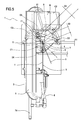
Figure 6 is a schematic perspective view from above, with some parts cut away for clarity, illustrating a portion of the band saw machine of the preceding figures; -
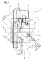
Figure 7 is a schematic top plan view showing a band saw machine according to the current state of the art and with the cutting unit in two different configurations of use. - With reference to
Figure 1 of the accompanying drawings, thereference numeral 1 denotes in its entirety a band saw machine made according to this invention. - The
band saw machine 1 comprises abase 2 constructed in such a way that it can be securely positioned on the floor or on a work bench, and acutting unit 3 connected to thebase 2 by means of amounting element 4. - The
base 2 has atop face 2a that defines a plane P. - The
mounting element 4 of thecutting unit 3 is movable relative to thebase 2 in the plane P to move thecutting unit 3 in such a way as to cut apart 10 at different angles. - The
cutting unit 3 comprises an endlesstoothed saw band 5 which is movable on arespective frame 6. Thesaw band 5 is trained in a loop around respective pulleys not shown in the drawings and has at least one cutting portion consisting of a set of teeth (not illustrated) whose cutting edge is inclined, as is customary, by a predetermined angle to the feed direction of thesaw band 5 itself. - Of the aforementioned pulleys not illustrated, one is idle and the other is driven by a respective motor M, also mounted on the
frame 6. - Mounted on the
base 2 is aclamping element 7, for example a vice, for locking apart 10 to be cut, the latter being drawn with dashed lines inFigure 1 . - The
vice 7 has a fixedjaw 7a, mounted squarely relative to abottom 7b integral with it, and amovable jaw 7c. - The
bottom 7b defines a supporting surface for thepart 10 to be cut. - With its locating wall for the
part 10, thefixed jaw 7a defines a plane P1. - The
movable jaw 7c is adapted to be moved, in known manner, towards the fixedjaw 7a by means of a threadedrod 7d, so that the part to be cut is clamped between the two jaws. - In alternative embodiments which are not illustrated,
part 10 to be cut is supported directly by thebase 2. That is to say there are no clamping elements like thevice 7. - In the case illustrated, where the
vice 7 is present, thebase 2 supports thepart 10 indirectly. - The
frame 6 of thecutting unit 3 is rotatably supported by themounting element 4 in such a way as to rotate about a horizontal axis A1 and so that thecutting unit 3 can move between a first, lowered position where the rotatingband 5 works on thepart 10 to be cut, and a second, raised position (illustrated inFigure 1 ) where theband 5 is disengaged from thepart 10 to be cut. - The
machine 1 further comprises anactuating lever 8 connected to one end of theframe 3, thelever 8 being usable by an operator to move thecutting unit 3 between the above mentioned first and second positions. Mounted advantageously on thelever 8 is a pushbutton, not illustrated, for starting themachine 1. - The rotating
band 5 is movable relative to theframe 3, in known manner, along a ring-shaped path having an active, preferably straight, cutting stretch T. At the active stretch T, theband 5 is adapted to come into contact with thepart 10 to be cut when the user lowers thecutting unit 3 towards thebase 2. - The aforementioned active stretch T starts in the proximity of a pair of
band 5guide rollers 11, each of the rollers coming into contact with a respective face of theband 5. - As illustrated in
Figures 5 and6 , thebase 2 has a plurality of cams C1, C2, C3 formed on it. - The
mounting element 4 of thecutting unit 3 has a plurality of follower elements D1, D2, D3 adapted to engage the cams C1, C2, C3 to define respective cam and follower mechanisms. - Advantageously, the cams C1, C2, C3 are slotted cams adapted to apply positive control to the respective follower elements D1, D2, D3. Advantageously, to guarantee smoothness in the movement of the cutting unit relative to the
base 2, better described below, the follower elements D2, D3 are operatively connected to each other, under thebase 2, by alink bar 9. - As illustrated in
Figures 2 to 4 , thecutting unit 3 is movable relative to thebase 2 as one with themounting element 4 according to a composite motion, the respective law of motion being applied by the assembly composed of thecutting unit 3 and themounting element 4 with the specially shaped and mutually arranged cams C1, C2, C3. This composite motion, being different from plain rotation and substantially defining a roto-translation for thecutting unit 3, is designed to modify the cutting start point Y of theband 5 on thepart 10 to be cut according to the desired cutting angle. - In other words, once a
part 10 has been placed on thevice 7, thecutting unit 3 can be lowered until theband 5 comes into contact with thepart 10 to identify on the stationary band 5 a point Y (being a virtual point fixed in space because, in use, theband 5 moves by virtue of its cutting motion) which is defined as the point at which the band starts cutting the part. - Still with reference to
Figures 2 to 4 , it may be observed that following the movement of themounting element 4 and of thecutting unit 3 to make cuts at different angles, the point Y, while remaining fixed in space, changes its position relative to the active stretch T of theband 5, precisely because of the composite motion imparted to the assembly composed of thecutting unit 3 and therespective mounting element 4. - In effect, as
Figures 2 to 4 also clearly illustrate, taking as reference theband 5guide rollers 11, which are fixed relative to theframe 6 of the cutting unit, the distance between the cutting start point Y and therollers 11 changes from a minimum value x1 (at the 90° cutting position) to a higher value x3 (at the 45° cutting position) according to the different angle of the cut made on thepart 10. - The advantages achieved by the machine of this invention are made even more evident by comparing it with the state of the art as exemplified by the band saw machine illustrated in
Figure 7 . - With reference to
Figure 7 , the reference numeral 1' denotes in its entirety a prior art band saw machine where the components corresponding to those of themachine 1 of the preceding figures are labelled with the same reference numerals. By way of an example, in the drawing of the prior art machine 1', thepart 10 to be cut has a square cross section. -
Figure 7 also illustrates thecutting unit 3 in two different configurations: the first (drawn with an unbroken line) suitable for cutting thepart 10 at 90° and the second (drawn with a dashed line) suitable for cuts at an angle of 45°. - The two illustrations of the
cutting unit 3, at 90° and at 45°, represent the same number of configurations in which theband 5 adopts its cutting start position, that is, the position defining a point Y' where theband 5 comes into contact with the part to be cut, depending on the shape and size of the part itself. - Irrespective of whether the
part 10 is cut at 90° (band 5 drawn with unbroken line inFigure 7 ) or at 45° (band 5 drawn with dashed line inFigure 7 ), the cutting start point Y' does not vary because the movement of thecutting unit 3 consists of rotation only. - In other words, the rotation of the
mounting element 4, and thus of thecutting unit 3, from the 90° to the 45° position, occurs about a vertical axis passing precisely through the point Y' and, more generally, lying in a plane containing the locating surface of thefixed jaw 7a of thevice 7. According to a different aspect, the distinctive feature of the machine according to the invention may be described as a method for moving thecutting unit 3 of theband saw machine 1 between two positions of it: a first position where thesaw band 5 is adapted to make right-angle cuts on thepart 10 and a second position where theband 5 is adapted to make inclined cuts on thepart 10. During the movement of thecutting unit 3 and of themounting element 4 as one therewith between these two positions, theband 5, assumed for simplicity to be stationary (that is, not driven by the respective motor M) intersects at a plurality of points on it, a single straight line perpendicular to a supportingsurface 7b of thepart 10 to be cut and lying in a plane P1 defined by a fixed locating wall for theselfsame part 10. In other words, with reference toFigures 2 to 4 , the fixed straight line is simply a straight line perpendicular to the plane P of thebase 2 and passing through the cutting start point Y of theband 5 on the part to be cut. - The method described above thus makes it possible to roto-translate the
band 5 relative to the straight line through the cutting start point Y. The method is implemented by roto-translating thecutting unit 3 relative to thebase 2, the roto-translation being accomplished by means of the cam and follower mechanisms described above. Advantageously, the invention achieves the above mentioned aims. - Thanks to a composite motion of substantially roto-translational type it is possible to enhance the cutting capacity of the band saw machine without increasing the dimensions and footprint of the machine and of its components.
- In effect, modifying the position of the cutting start point Y of the
band 5 on thepart 10 has made it possible to greatly increase the active, working stretch T of the band itself. - In the prior art machines, the overall dimensions of the fixed
jaw 7a of the vice in practice made it impossible to use a large, potentially operative stretch of the saw band, labelled x4 inFigure 7 . In effect, the distance x4 between the cutting start point Y' and theguide rollers 11 necessarily had to be left free behind thejaw 7a so that the latter could be approached for 45° cuts so as to keep the cutting start point Y' on the part at the same position. - With the band saw machine according to the invention, this limitation has been easily overcome by introducing the roto-translational motion of the mounting
element 4 of thecutting unit 3, thanks to which the "useless" or unused stretch of the band, that is to say, the stretch corresponding to the distance x4, has in practice been eliminated, by making this stretch operative to all intents and purposes, at least in 90° cuts, where it has been possible to increase the maximum cutting size by 30% and more. - In conclusion, whereas with prior art band saw machines with rotating cutting unit, the "useless" stretch of the band, extending for a distance x4, was present in all cutting configurations, from 90° to 45°, the composite motion of this invention allows the same useless stretch to be made variable from a maximum distance of x3 for a 45° cut, to a minimum distance x1 for a 90° cut, which is, moreover the statistically most frequent type of cut.
- In other words, advantageously, according to the invention, it is possible to obtain much greater capacities compared to prior art machines of the same size and footprint, at least at the 90° cutting position.
- Purely by way of an example, a prior art band saw machine with a normal rotatable support was able to cut rectangles of a maximum of 150 mm. By simply converting the support into a roto-translating support, the machine's cutting capacity can be increased to 200 mm and over.
- In this description, the term "composite motion" has been used to mean any motion that is not plan circular motion or plain straight-line motion.
- The method for moving the cutting unit of a band saw machine described in this specification is an optimum embodiment .
- Possible less effective embodiments of the machine according to the invention might involve composite motions whereby the band does not slide in a straight line, so as to move the cutting start point on the part according to the angular cutting position and thereby making the operator's task more difficult because it means taking different measuring points on the part according to the angle of the cut to be made. These less effective embodiments, however, also fall within the scope of protection afforded by this invention.
- The invention described above is susceptible of industrial application and may be modified and adapted in many ways without thereby departing from the scope of the inventive concept.
Claims (6)
- A band saw machine, in particular for cutting metal, comprising- a base (2) adapted to also support, directly or indirectly, a part (10) to be cut,- a cutting unit (3) comprising a toothed saw band (5) and motor means (M) for driving the band (5) to cut the part (10),- an element (4) for mounting the cutting unit (3), the mounting element (4) being supported by the base (2) and being movable relative to it in a plane (P) defined by a top face of the base (2) itself, to move the cutting unit (3) in such a way as to make cuts at different angles, the cutting unit (3) being movable relative to the base (2) as one with the mounting element (4) according to a composite motion different from plain rotation and designed to modify the cutting start point (Y) of the band (5) on the part to be cut according to the desired cutting angle; characterized in that the composite motion is defined by at least one cam and follower mechanism, said mechanism comprising at least one cam (C1, C2, C3) and at least one follower (D1, D2, D3), one of the two being integral with the base (2) and the other of the two being integral with the cutting unit (3).
- The band saw machine according to claim 1, characterized in that the composite motion comprises a roto-translation.
- The band saw machine according to claim 1 or 2, characterized in that the cam (C1, C2, C3) is made on the base (2) and the follower (D1, D2, D3) is mounted on the cutting unit (3).
- The band saw machine according to any of the foregoing claims, characterized in that it comprises a plurality of cams (C1, C2, C3) and respective followers (D1, D2, D3).
- The band saw machine according to any of the claims from 1 to 4, where the cutting unit (3) comprises a pair of rollers (11) for guiding the saw band (5), characterized in that the distance between the cutting start point (Y) of the band on the part to be cut changes from a minimum value (x1) at a 90° cutting position of the cutting unit (3) to a higher value (x3) at a 45° cutting position.
- The band saw machine according to any of the claims from 1 to 5, characterized in that it comprises a vice (7) for locking a part (10) to be cut and mounted on the base (2).
Applications Claiming Priority (1)
| Application Number | Priority Date | Filing Date | Title |
|---|---|---|---|
| ITBO2010A000369A IT1400366B1 (en) | 2010-06-11 | 2010-06-11 | BAND SAW MACHINE |
Publications (2)
| Publication Number | Publication Date |
|---|---|
| EP2394769A1 EP2394769A1 (en) | 2011-12-14 |
| EP2394769B1 true EP2394769B1 (en) | 2013-05-01 |
Family
ID=43466653
Family Applications (1)
| Application Number | Title | Priority Date | Filing Date |
|---|---|---|---|
| EP20110168894 Active EP2394769B1 (en) | 2010-06-11 | 2011-06-07 | Band saw machine |
Country Status (3)
| Country | Link |
|---|---|
| EP (1) | EP2394769B1 (en) |
| ES (1) | ES2423657T3 (en) |
| IT (1) | IT1400366B1 (en) |
Families Citing this family (1)
| Publication number | Priority date | Publication date | Assignee | Title |
|---|---|---|---|---|
| ITBO20120202A1 (en) * | 2012-04-13 | 2013-10-14 | Femi S P A | BAND SAW MACHINE |
Family Cites Families (2)
| Publication number | Priority date | Publication date | Assignee | Title |
|---|---|---|---|---|
| US1576051A (en) * | 1924-10-30 | 1926-03-09 | Pittsburgh Erie Saw Company | Power saw |
| KR200443078Y1 (en) * | 2008-04-15 | 2009-01-07 | 유혜경 | A cutting device capable of changing cutting location |
-
2010
- 2010-06-11 IT ITBO2010A000369A patent/IT1400366B1/en active
-
2011
- 2011-06-07 EP EP20110168894 patent/EP2394769B1/en active Active
- 2011-06-07 ES ES11168894T patent/ES2423657T3/en active Active
Also Published As
| Publication number | Publication date |
|---|---|
| IT1400366B1 (en) | 2013-05-31 |
| EP2394769A1 (en) | 2011-12-14 |
| ITBO20100369A1 (en) | 2011-12-12 |
| ES2423657T3 (en) | 2013-09-23 |
Similar Documents
| Publication | Publication Date | Title |
|---|---|---|
| RU2413606C1 (en) | Paper log cutting machine | |
| CN101623878B (en) | Sheet-processing lathe | |
| CN103568084B (en) | Bamboo green removing cutter component and bamboo green removing device with same | |
| CN208787677U (en) | A kind of efficient aluminium sheet cutter device | |
| KR200443078Y1 (en) | A cutting device capable of changing cutting location | |
| KR20060096402A (en) | A board cutting device | |
| CN109093767A (en) | A kind of full-automatic double-end saw | |
| EP2743022A1 (en) | Cutting unit and panel saw machine comprising the cutting unit | |
| CN204449521U (en) | A kind of Manual tapping machine | |
| EP2394769B1 (en) | Band saw machine | |
| CN203582883U (en) | Tailoring device of sofa covering | |
| CN209364884U (en) | A kind of clamping feed arrangement, moso bamboo cutting machine and system for moso bamboo cutting machine | |
| CN210498624U (en) | Aluminum bar processing is with cuting device | |
| CN209902348U (en) | Strip-shaped stainless steel sheet cutting machine | |
| JP2011079109A (en) | Main frame vice device in band sawing machine | |
| CN204171463U (en) | Round steel sawing machine for cutting | |
| CN101774186B (en) | Insulation foam plate trimming device | |
| TWI504455B (en) | Moving mechanism for scroll sawing machines | |
| CN207448552U (en) | A kind of sheet cutting machine | |
| KR200355001Y1 (en) | Do frozen food automatic cuting apparatus band saw machine | |
| CN211104269U (en) | Reciprocating band saw cutting device | |
| CN208163855U (en) | A kind of automation fine woodwork band saw bed | |
| CN211221474U (en) | Stone material processing cutting device | |
| CN203542657U (en) | Automatic shearing mechanism of sofa cover shearing device | |
| CN209867566U (en) | Workpiece cutting device for electrical machinery |
Legal Events
| Date | Code | Title | Description |
|---|---|---|---|
| AK | Designated contracting states |
Kind code of ref document: A1 Designated state(s): AL AT BE BG CH CY CZ DE DK EE ES FI FR GB GR HR HU IE IS IT LI LT LU LV MC MK MT NL NO PL PT RO RS SE SI SK SM TR |
|
| AX | Request for extension of the european patent |
Extension state: BA ME |
|
| PUAI | Public reference made under article 153(3) epc to a published international application that has entered the european phase |
Free format text: ORIGINAL CODE: 0009012 |
|
| 17P | Request for examination filed |
Effective date: 20120308 |
|
| RIC1 | Information provided on ipc code assigned before grant |
Ipc: B23D 53/04 20060101AFI20121017BHEP Ipc: B23D 53/12 20060101ALI20121017BHEP |
|
| GRAP | Despatch of communication of intention to grant a patent |
Free format text: ORIGINAL CODE: EPIDOSNIGR1 |
|
| GRAS | Grant fee paid |
Free format text: ORIGINAL CODE: EPIDOSNIGR3 |
|
| GRAA | (expected) grant |
Free format text: ORIGINAL CODE: 0009210 |
|
| AK | Designated contracting states |
Kind code of ref document: B1 Designated state(s): AL AT BE BG CH CY CZ DE DK EE ES FI FR GB GR HR HU IE IS IT LI LT LU LV MC MK MT NL NO PL PT RO RS SE SI SK SM TR |
|
| REG | Reference to a national code |
Ref country code: GB Ref legal event code: FG4D |
|
| REG | Reference to a national code |
Ref country code: CH Ref legal event code: EP Ref country code: AT Ref legal event code: REF Ref document number: 609579 Country of ref document: AT Kind code of ref document: T Effective date: 20130515 |
|
| REG | Reference to a national code |
Ref country code: IE Ref legal event code: FG4D |
|
| REG | Reference to a national code |
Ref country code: DE Ref legal event code: R096 Ref document number: 602011001514 Country of ref document: DE Effective date: 20130627 |
|
| REG | Reference to a national code |
Ref country code: AT Ref legal event code: MK05 Ref document number: 609579 Country of ref document: AT Kind code of ref document: T Effective date: 20130501 |
|
| REG | Reference to a national code |
Ref country code: ES Ref legal event code: FG2A Ref document number: 2423657 Country of ref document: ES Kind code of ref document: T3 Effective date: 20130923 |
|
| REG | Reference to a national code |
Ref country code: NL Ref legal event code: VDEP Effective date: 20130501 |
|
| REG | Reference to a national code |
Ref country code: LT Ref legal event code: MG4D |
|
| PG25 | Lapsed in a contracting state [announced via postgrant information from national office to epo] |
Ref country code: AT Free format text: LAPSE BECAUSE OF FAILURE TO SUBMIT A TRANSLATION OF THE DESCRIPTION OR TO PAY THE FEE WITHIN THE PRESCRIBED TIME-LIMIT Effective date: 20130501 Ref country code: SI Free format text: LAPSE BECAUSE OF FAILURE TO SUBMIT A TRANSLATION OF THE DESCRIPTION OR TO PAY THE FEE WITHIN THE PRESCRIBED TIME-LIMIT Effective date: 20130501 Ref country code: PT Free format text: LAPSE BECAUSE OF FAILURE TO SUBMIT A TRANSLATION OF THE DESCRIPTION OR TO PAY THE FEE WITHIN THE PRESCRIBED TIME-LIMIT Effective date: 20130902 Ref country code: NO Free format text: LAPSE BECAUSE OF FAILURE TO SUBMIT A TRANSLATION OF THE DESCRIPTION OR TO PAY THE FEE WITHIN THE PRESCRIBED TIME-LIMIT Effective date: 20130801 Ref country code: LT Free format text: LAPSE BECAUSE OF FAILURE TO SUBMIT A TRANSLATION OF THE DESCRIPTION OR TO PAY THE FEE WITHIN THE PRESCRIBED TIME-LIMIT Effective date: 20130501 Ref country code: SE Free format text: LAPSE BECAUSE OF FAILURE TO SUBMIT A TRANSLATION OF THE DESCRIPTION OR TO PAY THE FEE WITHIN THE PRESCRIBED TIME-LIMIT Effective date: 20130501 Ref country code: FI Free format text: LAPSE BECAUSE OF FAILURE TO SUBMIT A TRANSLATION OF THE DESCRIPTION OR TO PAY THE FEE WITHIN THE PRESCRIBED TIME-LIMIT Effective date: 20130501 Ref country code: IS Free format text: LAPSE BECAUSE OF FAILURE TO SUBMIT A TRANSLATION OF THE DESCRIPTION OR TO PAY THE FEE WITHIN THE PRESCRIBED TIME-LIMIT Effective date: 20130901 Ref country code: GR Free format text: LAPSE BECAUSE OF FAILURE TO SUBMIT A TRANSLATION OF THE DESCRIPTION OR TO PAY THE FEE WITHIN THE PRESCRIBED TIME-LIMIT Effective date: 20130802 |
|
| PG25 | Lapsed in a contracting state [announced via postgrant information from national office to epo] |
Ref country code: CY Free format text: LAPSE BECAUSE OF FAILURE TO SUBMIT A TRANSLATION OF THE DESCRIPTION OR TO PAY THE FEE WITHIN THE PRESCRIBED TIME-LIMIT Effective date: 20130501 Ref country code: BG Free format text: LAPSE BECAUSE OF FAILURE TO SUBMIT A TRANSLATION OF THE DESCRIPTION OR TO PAY THE FEE WITHIN THE PRESCRIBED TIME-LIMIT Effective date: 20130801 Ref country code: PL Free format text: LAPSE BECAUSE OF FAILURE TO SUBMIT A TRANSLATION OF THE DESCRIPTION OR TO PAY THE FEE WITHIN THE PRESCRIBED TIME-LIMIT Effective date: 20130501 Ref country code: RS Free format text: LAPSE BECAUSE OF FAILURE TO SUBMIT A TRANSLATION OF THE DESCRIPTION OR TO PAY THE FEE WITHIN THE PRESCRIBED TIME-LIMIT Effective date: 20130501 Ref country code: HR Free format text: LAPSE BECAUSE OF FAILURE TO SUBMIT A TRANSLATION OF THE DESCRIPTION OR TO PAY THE FEE WITHIN THE PRESCRIBED TIME-LIMIT Effective date: 20130501 |
|
| PG25 | Lapsed in a contracting state [announced via postgrant information from national office to epo] |
Ref country code: LV Free format text: LAPSE BECAUSE OF FAILURE TO SUBMIT A TRANSLATION OF THE DESCRIPTION OR TO PAY THE FEE WITHIN THE PRESCRIBED TIME-LIMIT Effective date: 20130501 |
|
| PG25 | Lapsed in a contracting state [announced via postgrant information from national office to epo] |
Ref country code: BE Free format text: LAPSE BECAUSE OF FAILURE TO SUBMIT A TRANSLATION OF THE DESCRIPTION OR TO PAY THE FEE WITHIN THE PRESCRIBED TIME-LIMIT Effective date: 20130501 Ref country code: EE Free format text: LAPSE BECAUSE OF FAILURE TO SUBMIT A TRANSLATION OF THE DESCRIPTION OR TO PAY THE FEE WITHIN THE PRESCRIBED TIME-LIMIT Effective date: 20130501 Ref country code: SK Free format text: LAPSE BECAUSE OF FAILURE TO SUBMIT A TRANSLATION OF THE DESCRIPTION OR TO PAY THE FEE WITHIN THE PRESCRIBED TIME-LIMIT Effective date: 20130501 Ref country code: MC Free format text: LAPSE BECAUSE OF FAILURE TO SUBMIT A TRANSLATION OF THE DESCRIPTION OR TO PAY THE FEE WITHIN THE PRESCRIBED TIME-LIMIT Effective date: 20130501 Ref country code: DK Free format text: LAPSE BECAUSE OF FAILURE TO SUBMIT A TRANSLATION OF THE DESCRIPTION OR TO PAY THE FEE WITHIN THE PRESCRIBED TIME-LIMIT Effective date: 20130501 Ref country code: CZ Free format text: LAPSE BECAUSE OF FAILURE TO SUBMIT A TRANSLATION OF THE DESCRIPTION OR TO PAY THE FEE WITHIN THE PRESCRIBED TIME-LIMIT Effective date: 20130501 |
|
| PG25 | Lapsed in a contracting state [announced via postgrant information from national office to epo] |
Ref country code: NL Free format text: LAPSE BECAUSE OF FAILURE TO SUBMIT A TRANSLATION OF THE DESCRIPTION OR TO PAY THE FEE WITHIN THE PRESCRIBED TIME-LIMIT Effective date: 20130501 Ref country code: RO Free format text: LAPSE BECAUSE OF FAILURE TO SUBMIT A TRANSLATION OF THE DESCRIPTION OR TO PAY THE FEE WITHIN THE PRESCRIBED TIME-LIMIT Effective date: 20130501 |
|
| PLBE | No opposition filed within time limit |
Free format text: ORIGINAL CODE: 0009261 |
|
| STAA | Information on the status of an ep patent application or granted ep patent |
Free format text: STATUS: NO OPPOSITION FILED WITHIN TIME LIMIT |
|
| REG | Reference to a national code |
Ref country code: IE Ref legal event code: MM4A |
|
| REG | Reference to a national code |
Ref country code: FR Ref legal event code: ST Effective date: 20140228 |
|
| 26N | No opposition filed |
Effective date: 20140204 |
|
| PG25 | Lapsed in a contracting state [announced via postgrant information from national office to epo] |
Ref country code: IE Free format text: LAPSE BECAUSE OF NON-PAYMENT OF DUE FEES Effective date: 20130607 |
|
| REG | Reference to a national code |
Ref country code: DE Ref legal event code: R097 Ref document number: 602011001514 Country of ref document: DE Effective date: 20140204 |
|
| PG25 | Lapsed in a contracting state [announced via postgrant information from national office to epo] |
Ref country code: FR Free format text: LAPSE BECAUSE OF NON-PAYMENT OF DUE FEES Effective date: 20130701 |
|
| REG | Reference to a national code |
Ref country code: CH Ref legal event code: PL |
|
| PG25 | Lapsed in a contracting state [announced via postgrant information from national office to epo] |
Ref country code: MT Free format text: LAPSE BECAUSE OF FAILURE TO SUBMIT A TRANSLATION OF THE DESCRIPTION OR TO PAY THE FEE WITHIN THE PRESCRIBED TIME-LIMIT Effective date: 20130501 |
|
| PG25 | Lapsed in a contracting state [announced via postgrant information from national office to epo] |
Ref country code: LI Free format text: LAPSE BECAUSE OF NON-PAYMENT OF DUE FEES Effective date: 20140630 Ref country code: CH Free format text: LAPSE BECAUSE OF NON-PAYMENT OF DUE FEES Effective date: 20140630 |
|
| PG25 | Lapsed in a contracting state [announced via postgrant information from national office to epo] |
Ref country code: SM Free format text: LAPSE BECAUSE OF FAILURE TO SUBMIT A TRANSLATION OF THE DESCRIPTION OR TO PAY THE FEE WITHIN THE PRESCRIBED TIME-LIMIT Effective date: 20130501 |
|
| PG25 | Lapsed in a contracting state [announced via postgrant information from national office to epo] |
Ref country code: TR Free format text: LAPSE BECAUSE OF FAILURE TO SUBMIT A TRANSLATION OF THE DESCRIPTION OR TO PAY THE FEE WITHIN THE PRESCRIBED TIME-LIMIT Effective date: 20130501 |
|
| PG25 | Lapsed in a contracting state [announced via postgrant information from national office to epo] |
Ref country code: MK Free format text: LAPSE BECAUSE OF FAILURE TO SUBMIT A TRANSLATION OF THE DESCRIPTION OR TO PAY THE FEE WITHIN THE PRESCRIBED TIME-LIMIT Effective date: 20130501 Ref country code: LU Free format text: LAPSE BECAUSE OF NON-PAYMENT OF DUE FEES Effective date: 20130607 Ref country code: HU Free format text: LAPSE BECAUSE OF FAILURE TO SUBMIT A TRANSLATION OF THE DESCRIPTION OR TO PAY THE FEE WITHIN THE PRESCRIBED TIME-LIMIT; INVALID AB INITIO Effective date: 20110607 |
|
| GBPC | Gb: european patent ceased through non-payment of renewal fee |
Effective date: 20150607 |
|
| PG25 | Lapsed in a contracting state [announced via postgrant information from national office to epo] |
Ref country code: GB Free format text: LAPSE BECAUSE OF NON-PAYMENT OF DUE FEES Effective date: 20150607 |
|
| PG25 | Lapsed in a contracting state [announced via postgrant information from national office to epo] |
Ref country code: AL Free format text: LAPSE BECAUSE OF FAILURE TO SUBMIT A TRANSLATION OF THE DESCRIPTION OR TO PAY THE FEE WITHIN THE PRESCRIBED TIME-LIMIT Effective date: 20130501 |
|
| PGFP | Annual fee paid to national office [announced via postgrant information from national office to epo] |
Ref country code: IT Payment date: 20230606 Year of fee payment: 13 Ref country code: DE Payment date: 20230627 Year of fee payment: 13 |
|
| PGFP | Annual fee paid to national office [announced via postgrant information from national office to epo] |
Ref country code: ES Payment date: 20230721 Year of fee payment: 13 |