EP2394707A1 - Handle with changeable grip - Google Patents
Handle with changeable grip Download PDFInfo
- Publication number
- EP2394707A1 EP2394707A1 EP11004676A EP11004676A EP2394707A1 EP 2394707 A1 EP2394707 A1 EP 2394707A1 EP 11004676 A EP11004676 A EP 11004676A EP 11004676 A EP11004676 A EP 11004676A EP 2394707 A1 EP2394707 A1 EP 2394707A1
- Authority
- EP
- European Patent Office
- Prior art keywords
- handle
- grip
- tubular member
- changeable
- changeable grip
- Prior art date
- Legal status (The legal status is an assumption and is not a legal conclusion. Google has not performed a legal analysis and makes no representation as to the accuracy of the status listed.)
- Withdrawn
Links
- 230000035939 shock Effects 0.000 claims abstract description 15
- 239000000463 material Substances 0.000 claims description 9
- 238000007373 indentation Methods 0.000 claims description 6
- OKTJSMMVPCPJKN-UHFFFAOYSA-N Carbon Chemical compound [C] OKTJSMMVPCPJKN-UHFFFAOYSA-N 0.000 claims description 3
- 239000013536 elastomeric material Substances 0.000 claims description 3
- 229910052751 metal Inorganic materials 0.000 claims description 3
- 239000002184 metal Substances 0.000 claims description 3
- 239000012815 thermoplastic material Substances 0.000 claims description 3
- 229910000831 Steel Inorganic materials 0.000 claims description 2
- RTAQQCXQSZGOHL-UHFFFAOYSA-N Titanium Chemical compound [Ti] RTAQQCXQSZGOHL-UHFFFAOYSA-N 0.000 claims description 2
- 229910052782 aluminium Inorganic materials 0.000 claims description 2
- XAGFODPZIPBFFR-UHFFFAOYSA-N aluminium Chemical compound [Al] XAGFODPZIPBFFR-UHFFFAOYSA-N 0.000 claims description 2
- 239000011152 fibreglass Substances 0.000 claims description 2
- 239000010439 graphite Substances 0.000 claims description 2
- 229910002804 graphite Inorganic materials 0.000 claims description 2
- 229910001092 metal group alloy Inorganic materials 0.000 claims description 2
- 239000000203 mixture Substances 0.000 claims description 2
- 229920003052 natural elastomer Polymers 0.000 claims description 2
- 229920001194 natural rubber Polymers 0.000 claims description 2
- 229920001296 polysiloxane Polymers 0.000 claims description 2
- 239000010959 steel Substances 0.000 claims description 2
- 229920003051 synthetic elastomer Polymers 0.000 claims description 2
- 239000005061 synthetic rubber Substances 0.000 claims description 2
- 239000010936 titanium Substances 0.000 claims description 2
- 229910052719 titanium Inorganic materials 0.000 claims description 2
- 244000043261 Hevea brasiliensis Species 0.000 claims 1
- 229920001971 elastomer Polymers 0.000 description 6
- 239000005060 rubber Substances 0.000 description 6
- 235000009854 Cucurbita moschata Nutrition 0.000 description 2
- 240000001980 Cucurbita pepo Species 0.000 description 2
- 235000009852 Cucurbita pepo Nutrition 0.000 description 2
- 239000000835 fiber Substances 0.000 description 2
- 239000010985 leather Substances 0.000 description 2
- 239000004033 plastic Substances 0.000 description 2
- 235000020354 squash Nutrition 0.000 description 2
- 238000004260 weight control Methods 0.000 description 2
- 238000010521 absorption reaction Methods 0.000 description 1
- 229910052799 carbon Inorganic materials 0.000 description 1
- 239000003086 colorant Substances 0.000 description 1
- 150000001875 compounds Chemical class 0.000 description 1
- 238000010276 construction Methods 0.000 description 1
- 230000002708 enhancing effect Effects 0.000 description 1
- 230000001747 exhibiting effect Effects 0.000 description 1
- 238000007542 hardness measurement Methods 0.000 description 1
- 239000002649 leather substitute Substances 0.000 description 1
- 239000007769 metal material Substances 0.000 description 1
Images


Classifications
-
- A—HUMAN NECESSITIES
- A63—SPORTS; GAMES; AMUSEMENTS
- A63B—APPARATUS FOR PHYSICAL TRAINING, GYMNASTICS, SWIMMING, CLIMBING, OR FENCING; BALL GAMES; TRAINING EQUIPMENT
- A63B49/00—Stringed rackets, e.g. for tennis
- A63B49/02—Frames
- A63B49/08—Frames with special construction of the handle
-
- A—HUMAN NECESSITIES
- A63—SPORTS; GAMES; AMUSEMENTS
- A63B—APPARATUS FOR PHYSICAL TRAINING, GYMNASTICS, SWIMMING, CLIMBING, OR FENCING; BALL GAMES; TRAINING EQUIPMENT
- A63B53/00—Golf clubs
- A63B53/14—Handles
-
- A—HUMAN NECESSITIES
- A63—SPORTS; GAMES; AMUSEMENTS
- A63B—APPARATUS FOR PHYSICAL TRAINING, GYMNASTICS, SWIMMING, CLIMBING, OR FENCING; BALL GAMES; TRAINING EQUIPMENT
- A63B60/00—Details or accessories of golf clubs, bats, rackets or the like
- A63B60/06—Handles
- A63B60/08—Handles characterised by the material
-
- A—HUMAN NECESSITIES
- A63—SPORTS; GAMES; AMUSEMENTS
- A63B—APPARATUS FOR PHYSICAL TRAINING, GYMNASTICS, SWIMMING, CLIMBING, OR FENCING; BALL GAMES; TRAINING EQUIPMENT
- A63B60/00—Details or accessories of golf clubs, bats, rackets or the like
- A63B60/06—Handles
- A63B60/14—Coverings specially adapted for handles, e.g. sleeves or ribbons
-
- A—HUMAN NECESSITIES
- A63—SPORTS; GAMES; AMUSEMENTS
- A63B—APPARATUS FOR PHYSICAL TRAINING, GYMNASTICS, SWIMMING, CLIMBING, OR FENCING; BALL GAMES; TRAINING EQUIPMENT
- A63B60/00—Details or accessories of golf clubs, bats, rackets or the like
- A63B60/06—Handles
- A63B60/16—Caps; Ferrules
-
- B—PERFORMING OPERATIONS; TRANSPORTING
- B25—HAND TOOLS; PORTABLE POWER-DRIVEN TOOLS; MANIPULATORS
- B25G—HANDLES FOR HAND IMPLEMENTS
- B25G1/00—Handle constructions
- B25G1/10—Handle constructions characterised by material or shape
-
- A—HUMAN NECESSITIES
- A63—SPORTS; GAMES; AMUSEMENTS
- A63B—APPARATUS FOR PHYSICAL TRAINING, GYMNASTICS, SWIMMING, CLIMBING, OR FENCING; BALL GAMES; TRAINING EQUIPMENT
- A63B71/00—Games or sports accessories not covered in groups A63B1/00 - A63B69/00
- A63B71/06—Indicating or scoring devices for games or players, or for other sports activities
- A63B71/0619—Displays, user interfaces and indicating devices, specially adapted for sport equipment, e.g. display mounted on treadmills
- A63B2071/0655—Tactile feedback
-
- A—HUMAN NECESSITIES
- A63—SPORTS; GAMES; AMUSEMENTS
- A63B—APPARATUS FOR PHYSICAL TRAINING, GYMNASTICS, SWIMMING, CLIMBING, OR FENCING; BALL GAMES; TRAINING EQUIPMENT
- A63B59/00—Bats, rackets, or the like, not covered by groups A63B49/00 - A63B57/00
- A63B59/20—Bats, rackets, or the like, not covered by groups A63B49/00 - A63B57/00 having means, e.g. pockets, netting or adhesive type surfaces, for catching or holding a ball, e.g. for lacrosse or pelota
-
- A—HUMAN NECESSITIES
- A63—SPORTS; GAMES; AMUSEMENTS
- A63B—APPARATUS FOR PHYSICAL TRAINING, GYMNASTICS, SWIMMING, CLIMBING, OR FENCING; BALL GAMES; TRAINING EQUIPMENT
- A63B60/00—Details or accessories of golf clubs, bats, rackets or the like
- A63B60/06—Handles
-
- A—HUMAN NECESSITIES
- A63—SPORTS; GAMES; AMUSEMENTS
- A63B—APPARATUS FOR PHYSICAL TRAINING, GYMNASTICS, SWIMMING, CLIMBING, OR FENCING; BALL GAMES; TRAINING EQUIPMENT
- A63B60/00—Details or accessories of golf clubs, bats, rackets or the like
- A63B60/06—Handles
- A63B60/10—Handles with means for indicating correct holding positions
-
- A—HUMAN NECESSITIES
- A63—SPORTS; GAMES; AMUSEMENTS
- A63B—APPARATUS FOR PHYSICAL TRAINING, GYMNASTICS, SWIMMING, CLIMBING, OR FENCING; BALL GAMES; TRAINING EQUIPMENT
- A63B60/00—Details or accessories of golf clubs, bats, rackets or the like
- A63B60/06—Handles
- A63B60/32—Handles with means for changing the angular position of the handle about its longitudinal axis
-
- A—HUMAN NECESSITIES
- A63—SPORTS; GAMES; AMUSEMENTS
- A63B—APPARATUS FOR PHYSICAL TRAINING, GYMNASTICS, SWIMMING, CLIMBING, OR FENCING; BALL GAMES; TRAINING EQUIPMENT
- A63B69/00—Training appliances or apparatus for special sports
- A63B69/36—Training appliances or apparatus for special sports for golf
- A63B69/3623—Training appliances or apparatus for special sports for golf for driving
- A63B69/3632—Clubs or attachments on clubs, e.g. for measuring, aligning
-
- A—HUMAN NECESSITIES
- A63—SPORTS; GAMES; AMUSEMENTS
- A63B—APPARATUS FOR PHYSICAL TRAINING, GYMNASTICS, SWIMMING, CLIMBING, OR FENCING; BALL GAMES; TRAINING EQUIPMENT
- A63B69/00—Training appliances or apparatus for special sports
- A63B69/36—Training appliances or apparatus for special sports for golf
- A63B69/3676—Training appliances or apparatus for special sports for golf for putting
- A63B69/3685—Putters or attachments on putters, e.g. for measuring, aligning
Definitions
- the present disclosure relates in general to a handle with a changeable grip particularly suited for shock imparting implements, and more particularly to a new and improved golf club shaft with a changeable grip.
- a changeable grip provides greater flexibility in selecting a specific grip for a given application or for use under a wide variety of conditions. It allows the user to select exactly the type of grip needed under the given conditions for the desired application. It is also desirable for the grip to be constructed in a manner that provides a firm grasp with little or no slippage and with good resistance to torque as well as exhibiting good shock absorbing qualities.
- a changeable grip further allows for a wide variety of enhancing features to the grip such as designing the grip weight for swing weight control, or even still multiple types of gripping surfaces with interchangeable gripping sleeves of combinations of various materials.
- Swing weight control, handle stiffness, flex control, shock absorption are just some of the important factors in improving the impact from the implement.
- the concept of tailoring a grip to provide the user with multiple options minimizes the need for multiple grips and multiple implements.
- the present disclosure describes a handle with a changeable grip for a shock imparting implement that offers a wide variety of features.
- the handle with the changeable grip includes an elongated tubular member having an initial diameter with two ends.
- a first end is constructed for attachment to a working head.
- the second end terminates in a butt end with a threaded indentation.
- the second end further includes a bell shaped section spaced from the butt end towards the first end.
- the bell shaped section has a diameter larger in size than the initial diameter which then reduces in size to form a ledge.
- the lower end of a gripping sleeve is slidably received on the second end of the elongated tubular member where it abuts the ledge.
- a cap with a threaded fastener meshes with the threaded indentation in the butt end of the handle to compress the gripping sleeve up against the ledge.
- the handle with changeable grip is particularly suited for use as a golf club shaft with a changeable golf club grip.
- the design of the present disclosure accommodates the U.S. Golf Association (“USGA”) rules requirement for the shaft to extend the full length of the shaft as well as provides a structure that has a simple configuration with reduced parts.
- USGA U.S. Golf Association
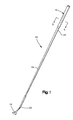
- Figure 1 is an elevated perspective view of a golf club
- Figure 2 is an exploded view of a portion of the golf club shaft and changeable grip according to the present disclosure
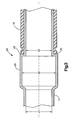
- Figure 3 is an enlarged sectional view of a portion of the golf club shaft and portion of the changeable golf grip according to an embodiment of the present disclosure
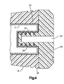
- Figure 4 is an enlarged sectional view of the butt end of the shaft and changeable grip according to an embodiment of the present disclosure
- Figure 5 is a sectional view of the shaft and changeable grip taken at lines 5-5 in Figure 1 according to an embodiment of the present disclosure.
- Figure 6 is a sectional view similar to Figure 5 depicting an alternate embodiment.
- a golf club generally designated 10.
- Golf club 10 includes a golf club grip 12, a shaft or handle 14, and a club head 16.
- a golf club is but one example of a shock imparting implement that the handle and changeable grip of the present disclosure finds utility.
- shock imparting implements known in the art.
- the term "shock imparting implement” as used herein is meant to include sporting implements and tools that are used to strike, impact, or apply a force to an object or an implement, or conversely receive an impact or force from the implement.
- shock imparting implements are but only a few examples meant to be included in the term "shock imparting implements".
- shock imparting implements Naturally there are many others, and even possibly more sport items that may still be developed. While particular reference is being made to a golf club handle with a changeable grip in the subject disclosure, it should be understood that the subject disclosure is applicable to any shock imparting implement including but not limited to other sporting implements and tool handles such as a hammer handle or a screwdriver handle.
- the changeable grip 12 basically comprises two parts or elements: a gripping sleeve 18, and a cap 20 which will be described in greater detail later herein.
- shaft 14 in one embodiment is an elongated tubular member made with an initial diameter (d1).
- the term "tubular” as used herein is meant to not only include a cylindrical shape or form, but also oval and other fairly cylindrically-shaped forms like polygons.
- the elongated tubular member 14 has a first and a second end 22, 24.
- a working head, like the club head 16, may be attached to the first end 22.
- the second end 24 of the handle 14 receives the gripping sleeve 18.
- the second end 24 of the handle 14 includes a bell shaped section 26 having a diameter (d2) larger than the initial diameter (d 1) of shaft 14.
- Bell shaped section 26 provides a ledge 28 integrally formed in handle 14.
- ledge 28 is formed in the shaft 14 by a sharp reduction in the diameter of the bell shaped section 26 to a diameter (d3) which may be equal in size to that of the initial diameter (d1), but does not have to be equal in size.
- a diameter (d3) which may be equal in size to that of the initial diameter (d1), but does not have to be equal in size.
- the butt end 32 of handle 14 has a threaded indentation 34 which may be a threaded aperture or simply an indentation with threads constructed to receive and mesh with a threaded fastener 36.
- Threaded fastener 36 may be an integral part of cap 20. Alternatively, fastener 36 may be separate from cap 20 simply passing through an opening 37 in cap 20 for securing the cap 20 to the handle 14. As cap 20 is tightened on to the handle 14 through fastener 36, the cap 20 can engage an upper end 38 of the gripping sleeve 18 to compress the gripping sleeve 18 against the ledge 28.
- handle 14 may contain splines or ribs 40 that extend longitudinally along the outer surface of the second end 24 of the handle 14.
- the splines 40 may also extend radially in the second end 24 of the handle in an alternate embodiment.
- the splines 40 mesh with channels 42 in the gripping sleeve 18 to serve as guides for slidably receiving the gripping sleeve 18 and prevent torsional slippage or rotation of the gripping sleeve 18 during use.
- an optional elongated rod 44 which may be a metal wire, rod, or an elastomeric line or rod is positioned fairly centrally in a slot 45 on one of the ridges 46 in the gripping sleeve 18 between the splines 40 to form a reminder rib 48 in the gripping sleeve 18 for a golfer.
- a reminder rib 48 is a device known and used by some golfers for facilitating their hand placement on the grip 12. The United States Golf Association rules require a reminder rib 48 not to be greater than about 0.04 inches or about 1 millimeter. The diameter of the rod 44 should be equal to or less than the 0.04 inches or 1 millimeter in order to comply with the golf rules.
- the location of the reminder rib 48 is adjustable by positioning the rod 44 in one of the slots 45 as seen in Figure 6 in a range of approximately five degrees to approximately fifteen degrees on either side of the center position of the ridge 46.
- Figure 6 depicts this feature with the rod positioned on either side of the center position at approximately five degrees, but it should be understood that this range can extend as much as approximately fifteen degrees.
- Handle 14 may be constructed from steel, aluminum, titanium or some other metal or metal alloy, fiberglass or graphite, and can be reinforced with carbon or other material fibers if desired.
- the gripping sleeve 18 and cap 20 may be made from natural or synthetic rubber, an elastomeric material like a rubber compound, a synthetic plastic, thermoplastic material, silicone material, or mixtures thereof, and may contain fibers or cords imbedded therein for a better gripping. Gripping sleeve 18 may contain on its outer surface indicia for decorative purposes, and/or grooves or notches for gripping purposes.
- the gripping sleeve 18 can further comprise one or more layers of a rubber, elastomeric, or thermoplastic material, or combinations of such materials. These layers can be arranged to provide varying durometer values.
- a durometer value or rating is an international standard for the hardness measurement of rubber, plastic and other non-metallic materials. Durometer values and ratings are described in the American Society for Testing and Material specification ASTM D2240.
- an inner surface of the sleeve 18 may have a hardness value ranging from approximately twenty-five to approximately fifty Shore A hardness.
- the outer surface or layer of the sleeve 18 can have a durometer value preferably ranging from approximately twenty -five to approximately ninety Shore A. Any combination of durometer values may be used depending upon the user's desire for a surface grip feel with good frictional qualities and tactile feel coupled with a firmer inner section.
- the improved changeable grip 12 of the present disclosure allows the user to select and change grips rapidly based on the optimum weight, feel, look, and moisture absorbency for a given application.
Landscapes
- Health & Medical Sciences (AREA)
- General Health & Medical Sciences (AREA)
- Physical Education & Sports Medicine (AREA)
- Engineering & Computer Science (AREA)
- Mechanical Engineering (AREA)
- Life Sciences & Earth Sciences (AREA)
- Biophysics (AREA)
- Golf Clubs (AREA)
- Mechanically-Actuated Valves (AREA)
- Details Of Rigid Or Semi-Rigid Containers (AREA)
Abstract
Description
- The present disclosure relates in general to a handle with a changeable grip particularly suited for shock imparting implements, and more particularly to a new and improved golf club shaft with a changeable grip.
- There are many forms of grips available on the market today for a wide variety of implements. These implements can range from hammer handles or other hand tools to sports implements like tennis, squash, or racquetball rackets, or golf clubs. While the present disclosure is particularly suited for a golf club shaft with a changeable grip and described with particular reference thereto, it should be immediately apparent that the present disclosure is not intended to be limited only to golf and extends to any sports grip or hand grip for a shock imparting implement.
- Originally, golf club grips consisted primarily of a leather wrap around a handle. Later, molded rubber slip-on grips became available and are still in wide use today. A recent variation on the molded rubber grip is the concept of using a rubber sleeve or underlisting on the handle with a leather or synthetic leather wrap spirally wrapped around the underlisting, or alternatively a single panel cover over the underlisting. Grips are made today from a wide variety in construction and combinations of materials.
- As the market demands a wider range of grips with different colors, weights, and sizes, producing a cost effective grip that meets a wide range of customer requirements is becoming very difficult. There still exists a need for an improved changeable grip that imparts or receives shock or force to or from a shock imparting implement. A changeable grip provides greater flexibility in selecting a specific grip for a given application or for use under a wide variety of conditions. It allows the user to select exactly the type of grip needed under the given conditions for the desired application. It is also desirable for the grip to be constructed in a manner that provides a firm grasp with little or no slippage and with good resistance to torque as well as exhibiting good shock absorbing qualities.
- A changeable grip further allows for a wide variety of enhancing features to the grip such as designing the grip weight for swing weight control, or even still multiple types of gripping surfaces with interchangeable gripping sleeves of combinations of various materials. Swing weight control, handle stiffness, flex control, shock absorption are just some of the important factors in improving the impact from the implement. The concept of tailoring a grip to provide the user with multiple options minimizes the need for multiple grips and multiple implements.
- Thus, it is desirable to have a changeable grip that allows the user to select the right fit and feel for the handle or shaft of a shock imparting implement or tool to meet the needs of the user in a given application.
- The present disclosure describes a handle with a changeable grip for a shock imparting implement that offers a wide variety of features.
- The handle with the changeable grip according to the present disclosure includes an elongated tubular member having an initial diameter with two ends. A first end is constructed for attachment to a working head. The second end terminates in a butt end with a threaded indentation. The second end further includes a bell shaped section spaced from the butt end towards the first end. The bell shaped section has a diameter larger in size than the initial diameter which then reduces in size to form a ledge. The lower end of a gripping sleeve is slidably received on the second end of the elongated tubular member where it abuts the ledge. A cap with a threaded fastener meshes with the threaded indentation in the butt end of the handle to compress the gripping sleeve up against the ledge.
- The handle with changeable grip is particularly suited for use as a golf club shaft with a changeable golf club grip. The design of the present disclosure accommodates the U.S. Golf Association ("USGA") rules requirement for the shaft to extend the full length of the shaft as well as provides a structure that has a simple configuration with reduced parts.
- The various features of novelty which characterize the present disclosure are pointed out with particularity in the claims annexed to and forming a part of this disclosure. For a better understanding of the present disclosure and its operating advantages attained with its use, reference is made to the accompanying drawings, and descriptive matter.
-
Figure 1 is an elevated perspective view of a golf club; -
Figure 2 is an exploded view of a portion of the golf club shaft and changeable grip according to the present disclosure -
Figure 3 is an enlarged sectional view of a portion of the golf club shaft and portion of the changeable golf grip according to an embodiment of the present disclosure; -
Figure 4 is an enlarged sectional view of the butt end of the shaft and changeable grip according to an embodiment of the present disclosure; -
Figure 5 is a sectional view of the shaft and changeable grip taken at lines 5-5 inFigure 1 according to an embodiment of the present disclosure; and -
Figure 6 is a sectional view similar toFigure 5 depicting an alternate embodiment. - Referring to the figures, which are not intended to limit the present disclosure, and where like numerals designate like or similar features throughout the several views, and first in particular to
Figure 1 , there is shown a golf club generally designated 10.Golf club 10 includes agolf club grip 12, a shaft or handle 14, and aclub head 16. A golf club is but one example of a shock imparting implement that the handle and changeable grip of the present disclosure finds utility. There are many other examples of shock imparting implements known in the art. The term "shock imparting implement" as used herein is meant to include sporting implements and tools that are used to strike, impact, or apply a force to an object or an implement, or conversely receive an impact or force from the implement. Tennis racquets, squash racquets, racquetball racquets, lacrosse grips, fishing rod handles, bicycle handles, motorcycle handles, gear shift levers, and baseball grips are but only a few examples meant to be included in the term "shock imparting implements". Naturally there are many others, and even possibly more sport items that may still be developed. While particular reference is being made to a golf club handle with a changeable grip in the subject disclosure, it should be understood that the subject disclosure is applicable to any shock imparting implement including but not limited to other sporting implements and tool handles such as a hammer handle or a screwdriver handle. - Referring to
Figure 2 , there is shown in exploded view a portion of theshaft 14 andchangeable grip 12 according to the present disclosure. Thechangeable grip 12 basically comprises two parts or elements: agripping sleeve 18, and acap 20 which will be described in greater detail later herein. - Turning now to
Figure 3 ,shaft 14 in one embodiment is an elongated tubular member made with an initial diameter (d1). The term "tubular" as used herein is meant to not only include a cylindrical shape or form, but also oval and other fairly cylindrically-shaped forms like polygons. The elongatedtubular member 14 has a first and asecond end club head 16, may be attached to thefirst end 22. Thesecond end 24 of thehandle 14 receives thegripping sleeve 18. In the present disclosure, thesecond end 24 of thehandle 14 includes a bellshaped section 26 having a diameter (d2) larger than the initial diameter (d 1) ofshaft 14. Bellshaped section 26 provides aledge 28 integrally formed inhandle 14. In one embodiment,ledge 28 is formed in theshaft 14 by a sharp reduction in the diameter of the bellshaped section 26 to a diameter (d3) which may be equal in size to that of the initial diameter (d1), but does not have to be equal in size. When thegripping sleeve 18 is slid on to handle 14, thelower end 30 abuts theledge 28 to hold thelower end 30 of thegripping sleeve 18 in place. The bell shapedsection 26 andledge 28 are spaced at a distance from abutt end 32 of thehandle 14 to fairly match the desired length of thegripping sleeve 18. - Next referring to
Figure 4 , thebutt end 32 ofhandle 14 has a threadedindentation 34 which may be a threaded aperture or simply an indentation with threads constructed to receive and mesh with a threadedfastener 36. Threadedfastener 36 may be an integral part ofcap 20. Alternatively,fastener 36 may be separate fromcap 20 simply passing through anopening 37 incap 20 for securing thecap 20 to thehandle 14. Ascap 20 is tightened on to thehandle 14 throughfastener 36, thecap 20 can engage anupper end 38 of thegripping sleeve 18 to compress thegripping sleeve 18 against theledge 28. - As seen in
Figures 5 and 6 , handle 14 may contain splines orribs 40 that extend longitudinally along the outer surface of thesecond end 24 of thehandle 14. Thesplines 40 may also extend radially in thesecond end 24 of the handle in an alternate embodiment. Thesplines 40 mesh withchannels 42 in thegripping sleeve 18 to serve as guides for slidably receiving thegripping sleeve 18 and prevent torsional slippage or rotation of thegripping sleeve 18 during use. - In still another embodiment, an optional
elongated rod 44 which may be a metal wire, rod, or an elastomeric line or rod is positioned fairly centrally in aslot 45 on one of theridges 46 in thegripping sleeve 18 between thesplines 40 to form areminder rib 48 in thegripping sleeve 18 for a golfer. Areminder rib 48 is a device known and used by some golfers for facilitating their hand placement on thegrip 12. The United States Golf Association rules require areminder rib 48 not to be greater than about 0.04 inches or about 1 millimeter. The diameter of therod 44 should be equal to or less than the 0.04 inches or 1 millimeter in order to comply with the golf rules. The location of thereminder rib 48 is adjustable by positioning therod 44 in one of theslots 45 as seen inFigure 6 in a range of approximately five degrees to approximately fifteen degrees on either side of the center position of theridge 46.Figure 6 depicts this feature with the rod positioned on either side of the center position at approximately five degrees, but it should be understood that this range can extend as much as approximately fifteen degrees. -
Handle 14 may be constructed from steel, aluminum, titanium or some other metal or metal alloy, fiberglass or graphite, and can be reinforced with carbon or other material fibers if desired. - The gripping
sleeve 18 andcap 20 may be made from natural or synthetic rubber, an elastomeric material like a rubber compound, a synthetic plastic, thermoplastic material, silicone material, or mixtures thereof, and may contain fibers or cords imbedded therein for a better gripping. Grippingsleeve 18 may contain on its outer surface indicia for decorative purposes, and/or grooves or notches for gripping purposes. - The gripping
sleeve 18 can further comprise one or more layers of a rubber, elastomeric, or thermoplastic material, or combinations of such materials. These layers can be arranged to provide varying durometer values. A durometer value or rating is an international standard for the hardness measurement of rubber, plastic and other non-metallic materials. Durometer values and ratings are described in the American Society for Testing and Material specification ASTM D2240. For example in one embodiment, an inner surface of thesleeve 18 may have a hardness value ranging from approximately twenty-five to approximately fifty Shore A hardness. The outer surface or layer of thesleeve 18 can have a durometer value preferably ranging from approximately twenty -five to approximately ninety Shore A. Any combination of durometer values may be used depending upon the user's desire for a surface grip feel with good frictional qualities and tactile feel coupled with a firmer inner section. - The improved
changeable grip 12 of the present disclosure allows the user to select and change grips rapidly based on the optimum weight, feel, look, and moisture absorbency for a given application. - While specific embodiments of the disclosure have been shown and described in detail to illustrate the application of the principles of this disclosure, it will be understood that there may be other embodiments based on this without departing from such principles.
Claims (15)
- A handle (14) with a changeable grip (12) for a shock imparting implement (10), comprising:an elongated tubular member (14) having an initial diameter (d1), said tubular member (14) having first and second ends (22,24), said first end (22) being constructed for attachment to a working head (16), said second end (24) of said elongated tubular member (14) terminating in a butt end (32), said butt end (32) having a threaded indentation (34) therein,said second end (24) having a bell-shaped section (26) spaced from said butt end, said bell-shaped section (26) having a diameter (d2) larger in size than said initial diameter (d1), said bell-shaped section (26) having a ledge (28) at an end, formed in said elongated tubular member, said ledge (28) of said bell-shaped portion (26) being spaced a distance from said butt end (32) of said elongated tubular member (14);a gripping sleeve (18) constructed to slide on to and cover at least a portion of said second end (24) of said tubular member (14), a lower end (30) of said gripping sleeve (18) abutting against said ledge (28);a cap (20) for covering an upper end (38) of said gripping sleeve (18); anda fastener (36) for securing said cap (20) and said gripping sleeve (18) to said handle (14), said fastener (36) constructed to mesh with said threaded indentation (34) in said butt end (32) of said tubular member (14).
- A handle (14) with a changeable grip (12) according to claim 1 wherein said handle (14) is a golf club shaft (14) with a changeable golf club grip (12).
- A handle (14) with a changeable grip (12) according to claim 2, wherein said golf club shaft (14) is a material being a member selected from the group consisting of steel, titanium, aluminum, a metal or metal alloy, fiberglass and graphite.
- A handle (14) with a changeable grip (12) according to claim 3, wherein said second end (24) of said tubular member (14) further comprises at least one spline (40).
- A handle (14) with a changeable grip (12) according to claim 4, wherein said at least one spline (40) extends longitudinally on said second end (24) of said elongated tubular member (14) towards said butt end (32).
- A handle (14) with a changeable grip (12) according to claim 5, wherein said gripping sleeve (18) includes at least one channel (42) constructed to mesh with said at least one spline (40) in said second end (24) of said tubular member (14).
- A handle (14) with a changeable grip (12) according to claim 4, wherein said at least one spline (40) comprises a plurality of splines (40).
- A handle (14) with a changeable grip (12) according to claim 6, wherein said at least one channel (42) comprises a plurality of channels (42) in said gripping sleeve (18).
- A handle (14) with a changeable grip (12) according to claim 8, wherein a ridge (46) on one of said channels (42) in said gripping sleeve (18) includes at least one slot (45) for positioning a rod (44) to form a reminder rib (48) for said grip.
- A handle (14) with a changeable grip (12), according to claim 1, wherein said gripping sleeve (28) is a material being a member selected from the group consisting of natural rubber, synthetic rubber, an elastomeric material, a thermoplastic material, a silicone material, and mixtures thereof.
- A handle (14) with a changeable grip (12) according to claim 9, wherein said ridge (46) on one of said channels (42) includes a plurality of slots (45) for positioning said rod (44) from approximately five degrees to approximately fifteen degrees on either said of a center position on said ridge (46) for forming said reminder rib (48).
- A handle (14) with a changeable grip (12) according to claim 1, further comprising a working head (16) attached to said first end (22) of said tubular member (14).
- A handle (14) with a changeable grip (12) according to claim 1, wherein said fastener (36) is formed integrally with said cap (20).
- A handle (14) with a changeable grip (12) according to claim 2, wherein said first end (22) of said golf club shaft (14) is attached to a club head (16).
- A handle (14) with a changeable grip (12) according to claim 4, wherein said at least one spline (40) comprises a plurality of splines (40) extending radially around said second end (24) of said tubular member (14).
Applications Claiming Priority (1)
| Application Number | Priority Date | Filing Date | Title |
|---|---|---|---|
| US12/795,772 US8419566B2 (en) | 2010-06-08 | 2010-06-08 | Handle with changeable grip |
Publications (1)
| Publication Number | Publication Date |
|---|---|
| EP2394707A1 true EP2394707A1 (en) | 2011-12-14 |
Family
ID=44558250
Family Applications (1)
| Application Number | Title | Priority Date | Filing Date |
|---|---|---|---|
| EP11004676A Withdrawn EP2394707A1 (en) | 2010-06-08 | 2011-06-08 | Handle with changeable grip |
Country Status (9)
| Country | Link |
|---|---|
| US (1) | US8419566B2 (en) |
| EP (1) | EP2394707A1 (en) |
| JP (1) | JP5939745B2 (en) |
| KR (1) | KR20110134325A (en) |
| CN (2) | CN202237111U (en) |
| AU (1) | AU2011202713B2 (en) |
| CA (1) | CA2742436A1 (en) |
| MX (1) | MX2011006155A (en) |
| TW (2) | TWI539983B (en) |
Families Citing this family (21)
| Publication number | Priority date | Publication date | Assignee | Title |
|---|---|---|---|---|
| US8814719B2 (en) * | 2012-06-19 | 2014-08-26 | Callaway Golf Company | Lightweight grip for sports equipment |
| US20140243120A1 (en) * | 2013-02-26 | 2014-08-28 | Easton Sports, Inc. | Multi-piece shaft for a lacrosse stick |
| JP2015080696A (en) * | 2013-10-24 | 2015-04-27 | 株式会社ジャパーナ | Golf club and golf club shaft length adjustment parts |
| JP2015150050A (en) * | 2014-02-12 | 2015-08-24 | ブリヂストンスポーツ株式会社 | Golf club shaft, characteristic adjustment method of the same, and golf club |
| KR101720650B1 (en) * | 2014-09-23 | 2017-04-10 | 심재철 | club for golf putter |
| US9889357B2 (en) | 2015-09-17 | 2018-02-13 | Ready Grip Technologies, LLC | Removable and reattachable golf club grip |
| US10500454B2 (en) | 2015-09-17 | 2019-12-10 | Ready Grip Technologies, Inc. | Removable and reattachable golf club grip |
| JP6450055B2 (en) | 2015-09-17 | 2019-01-09 | レディー グリップ テクノロジーズ エルエルシー | Removable and replaceable golf grip |
| CN105365981A (en) * | 2015-10-27 | 2016-03-02 | 无锡尊宝电动车有限公司 | Replacement type electric vehicle handle |
| US9586114B1 (en) * | 2016-04-25 | 2017-03-07 | Paul Chalifoux | Snap compression interchangeable golf grip |
| US9452333B1 (en) * | 2016-04-25 | 2016-09-27 | Paul Chalifoux | Compression interchangeable golf grip |
| US10052538B2 (en) | 2016-09-20 | 2018-08-21 | Eaton Intelligent Power, Ltd. | Golf grip with reminder rib |
| US9656133B1 (en) * | 2016-10-06 | 2017-05-23 | Paul Chalifoux | Expanding golf grip core |
| KR102071332B1 (en) * | 2016-10-20 | 2020-01-30 | 김경호 | Grip for golf club |
| US10010773B1 (en) | 2017-05-31 | 2018-07-03 | Scott J. Pugliese | Grip assemblies and related methods |
| US10118079B1 (en) * | 2017-10-10 | 2018-11-06 | Ronald Hayes | Putter head swinging assembly |
| US10143902B1 (en) * | 2017-11-15 | 2018-12-04 | Eaton Intelligent Power Limited | Flexible grip for a golf club and method of making same |
| USD849166S1 (en) | 2017-12-07 | 2019-05-21 | Ssg International, Llc | Golf putter grip |
| US10099101B1 (en) | 2017-12-07 | 2018-10-16 | Ssg International, Llc | Golf club grip with sensor housing |
| US11571612B2 (en) * | 2020-03-13 | 2023-02-07 | Ryan Harland Tarrant | Divot tool and method of manufacture thereof |
| US11369851B1 (en) | 2020-12-21 | 2022-06-28 | Ssg International Llc | Interchangeable golf club grip with shaft attachment system |
Citations (10)
| Publication number | Priority date | Publication date | Assignee | Title |
|---|---|---|---|---|
| US1626967A (en) * | 1927-01-24 | 1927-05-03 | Spalding & Bros Ag | Golf-club shaft |
| US4365807A (en) * | 1980-07-31 | 1982-12-28 | Melby Phillip J | Golf club including rotatable grip |
| GB2260499A (en) * | 1991-10-16 | 1993-04-21 | Taylor Made Golf Co | Golf club shaft. |
| US5730662A (en) * | 1996-10-21 | 1998-03-24 | Rens; Peter J. | Grip assembly and method |
| US5906548A (en) * | 1998-07-06 | 1999-05-25 | Hadge; Robert | Convertible golf club |
| US20020107088A1 (en) * | 2001-02-07 | 2002-08-08 | Lamkin Robert E. | Grip for sporting implement |
| US6511386B1 (en) * | 2001-09-06 | 2003-01-28 | D.B. Consolidated Enterprises, Inc. | Hand grip attachment with mechanical means for adjusting firmness and feel |
| US20060094525A1 (en) * | 2004-10-28 | 2006-05-04 | Chi-Chin Hung | Air cushion type sleeve of a handle of a golf club |
| EP1927439A1 (en) * | 2006-12-01 | 2008-06-04 | EATON Corporation | Variable mass grip |
| WO2008110888A1 (en) * | 2007-03-14 | 2008-09-18 | Eaton Corporation | Changeable golf grip |
Family Cites Families (31)
| Publication number | Priority date | Publication date | Assignee | Title |
|---|---|---|---|---|
| US2023131A (en) * | 1932-09-05 | 1935-12-03 | Gibson Robert James | Steel shaft for golf clubs |
| US2103889A (en) * | 1933-07-20 | 1937-12-28 | Kroydon Company | Golf club handle |
| US2871899A (en) * | 1958-04-16 | 1959-02-03 | Bridgeport Hardware Mfg Corp | Tool handles |
| US2941806A (en) * | 1958-10-13 | 1960-06-21 | Quinn O Stevens | Golf club |
| US3360264A (en) * | 1964-11-02 | 1967-12-26 | Lamkin Leather Company Inc | Golf club grip for shafts with diametral variations |
| US4461479A (en) * | 1981-02-13 | 1984-07-24 | Mitchell Michael D | Golf club having weighted handle |
| FR2681791B1 (en) * | 1991-09-27 | 1994-05-06 | Salomon Sa | VIBRATION DAMPING DEVICE FOR A GOLF CLUB. |
| FR2682607A1 (en) * | 1991-10-16 | 1993-04-23 | Taylor Made Golf Co | Improvement for a golf club |
| US5855525A (en) * | 1992-11-23 | 1999-01-05 | Turner; Terry S. | Golf club |
| US5374064A (en) * | 1993-07-26 | 1994-12-20 | Barber; Frederick E. | Golf club training apparatus |
| US5575724A (en) * | 1995-07-19 | 1996-11-19 | Golfology, Inc. | Alignment-oriented golf club |
| US5944617A (en) * | 1995-11-20 | 1999-08-31 | Pendulum Corporation | Vibration absorbing material for handles of sporting equipment |
| US5653643A (en) * | 1995-11-20 | 1997-08-05 | Pendulum Corp. | Vibration absorbing material for handles of sporting equipment |
| US5749798A (en) * | 1996-08-15 | 1998-05-12 | Wilson Sporting Goods Co. | Racket for tennis or the like games |
| US5713104A (en) | 1996-09-30 | 1998-02-03 | Giampaolo, Jr.; Joseph L. | Pneumatic compressed auxiliary implement handle for the manually impaired |
| JP3036832U (en) * | 1996-10-16 | 1997-05-06 | 景三 尤 | Golf club |
| US7261641B2 (en) * | 2002-02-04 | 2007-08-28 | Balance-Certified Golf, Inc. | Method and apparatus for improving dynamic response of golf club |
| US6749521B1 (en) | 2002-11-25 | 2004-06-15 | On Track Sports, L.L.C. | Extendable golf club having interlockable spacer segments |
| US7234205B2 (en) * | 2003-04-17 | 2007-06-26 | Shedrain Corporation | Pliable handle |
| US7435186B1 (en) | 2004-02-23 | 2008-10-14 | Miller R Lee | Golf club grip |
| US7479069B2 (en) * | 2004-11-24 | 2009-01-20 | Michael H. L. Cheng | Insert for altering the stiffness of a golf club shaft |
| DE102005037504B3 (en) * | 2004-12-23 | 2006-08-24 | Felo-Werkzeugfabrik Holland-Letz Gmbh | Use of a handle for a screwdriver |
| KR100584197B1 (en) | 2005-06-17 | 2006-06-07 | (주)인컴코리아 | Golf club grip and golf club with same |
| US7401384B2 (en) | 2005-09-30 | 2008-07-22 | Xiamen Jundian House Omaments Co., Ltd. | Pliable handle |
| US20080313859A1 (en) | 2007-06-19 | 2008-12-25 | Hsia Hui Chen | Soft handle having double layers of soft skins |
| WO2009064673A1 (en) | 2007-11-14 | 2009-05-22 | Board Of Regents, The University Of Texas System | Vibration reduction grip for golf clubs |
| US7758447B2 (en) | 2008-04-07 | 2010-07-20 | Taylor Made Golf Company, Inc. | Golf club grip |
| JP2010000155A (en) * | 2008-06-19 | 2010-01-07 | Sri Sports Ltd | Golf club |
| US7992258B1 (en) * | 2009-01-16 | 2011-08-09 | Catherine Stitser | Customized sports safety grips |
| US20100248858A1 (en) | 2009-03-25 | 2010-09-30 | Lu Clive S | Grip For Sporting Equipment |
| US8480510B2 (en) * | 2009-08-28 | 2013-07-09 | Ben Huang | Sleeve member for use in golf club grips and the like |
-
2010
- 2010-06-08 US US12/795,772 patent/US8419566B2/en not_active Expired - Fee Related
-
2011
- 2011-06-07 AU AU2011202713A patent/AU2011202713B2/en not_active Ceased
- 2011-06-07 CA CA2742436A patent/CA2742436A1/en not_active Abandoned
- 2011-06-08 KR KR1020110055009A patent/KR20110134325A/en not_active Ceased
- 2011-06-08 CN CN2011201967305U patent/CN202237111U/en not_active Expired - Fee Related
- 2011-06-08 CN CN201110159845.1A patent/CN102274617B/en not_active Expired - Fee Related
- 2011-06-08 MX MX2011006155A patent/MX2011006155A/en unknown
- 2011-06-08 JP JP2011128269A patent/JP5939745B2/en not_active Expired - Fee Related
- 2011-06-08 EP EP11004676A patent/EP2394707A1/en not_active Withdrawn
- 2011-06-08 TW TW100120023A patent/TWI539983B/en not_active IP Right Cessation
- 2011-06-08 TW TW100210393U patent/TWM433223U/en not_active IP Right Cessation
Patent Citations (10)
| Publication number | Priority date | Publication date | Assignee | Title |
|---|---|---|---|---|
| US1626967A (en) * | 1927-01-24 | 1927-05-03 | Spalding & Bros Ag | Golf-club shaft |
| US4365807A (en) * | 1980-07-31 | 1982-12-28 | Melby Phillip J | Golf club including rotatable grip |
| GB2260499A (en) * | 1991-10-16 | 1993-04-21 | Taylor Made Golf Co | Golf club shaft. |
| US5730662A (en) * | 1996-10-21 | 1998-03-24 | Rens; Peter J. | Grip assembly and method |
| US5906548A (en) * | 1998-07-06 | 1999-05-25 | Hadge; Robert | Convertible golf club |
| US20020107088A1 (en) * | 2001-02-07 | 2002-08-08 | Lamkin Robert E. | Grip for sporting implement |
| US6511386B1 (en) * | 2001-09-06 | 2003-01-28 | D.B. Consolidated Enterprises, Inc. | Hand grip attachment with mechanical means for adjusting firmness and feel |
| US20060094525A1 (en) * | 2004-10-28 | 2006-05-04 | Chi-Chin Hung | Air cushion type sleeve of a handle of a golf club |
| EP1927439A1 (en) * | 2006-12-01 | 2008-06-04 | EATON Corporation | Variable mass grip |
| WO2008110888A1 (en) * | 2007-03-14 | 2008-09-18 | Eaton Corporation | Changeable golf grip |
Also Published As
| Publication number | Publication date |
|---|---|
| MX2011006155A (en) | 2011-12-14 |
| US20110300966A1 (en) | 2011-12-08 |
| JP2011255183A (en) | 2011-12-22 |
| TWI539983B (en) | 2016-07-01 |
| JP5939745B2 (en) | 2016-06-22 |
| CN202237111U (en) | 2012-05-30 |
| CN102274617B (en) | 2016-09-28 |
| CA2742436A1 (en) | 2011-12-08 |
| TWM433223U (en) | 2012-07-11 |
| CN102274617A (en) | 2011-12-14 |
| AU2011202713A1 (en) | 2011-12-22 |
| TW201206528A (en) | 2012-02-16 |
| AU2011202713B2 (en) | 2013-07-25 |
| KR20110134325A (en) | 2011-12-14 |
| US8419566B2 (en) | 2013-04-16 |
Similar Documents
| Publication | Publication Date | Title |
|---|---|---|
| US8419566B2 (en) | Handle with changeable grip | |
| US8182361B2 (en) | Changeable grip | |
| US7798911B2 (en) | Changeable golf grip | |
| EP1927439B1 (en) | Variable mass grip | |
| US20150251062A1 (en) | Weighted golf club grip | |
| JP2014207972A (en) | Weighted grip of golf club |
Legal Events
| Date | Code | Title | Description |
|---|---|---|---|
| AK | Designated contracting states |
Kind code of ref document: A1 Designated state(s): AL AT BE BG CH CY CZ DE DK EE ES FI FR GB GR HR HU IE IS IT LI LT LU LV MC MK MT NL NO PL PT RO RS SE SI SK SM TR |
|
| AX | Request for extension of the european patent |
Extension state: BA ME |
|
| PUAI | Public reference made under article 153(3) epc to a published international application that has entered the european phase |
Free format text: ORIGINAL CODE: 0009012 |
|
| 17P | Request for examination filed |
Effective date: 20120614 |
|
| 17Q | First examination report despatched |
Effective date: 20160322 |
|
| GRAP | Despatch of communication of intention to grant a patent |
Free format text: ORIGINAL CODE: EPIDOSNIGR1 |
|
| RIC1 | Information provided on ipc code assigned before grant |
Ipc: A63B 59/00 20060101ALN20180416BHEP Ipc: A63B 71/06 20060101ALN20180416BHEP Ipc: B25G 1/00 20060101ALI20180416BHEP Ipc: A63B 53/14 20060101AFI20180416BHEP Ipc: A63B 69/36 20060101ALN20180416BHEP Ipc: A63B 60/14 20150101ALN20180416BHEP Ipc: A63B 49/08 20060101ALN20180416BHEP |
|
| INTG | Intention to grant announced |
Effective date: 20180508 |
|
| STAA | Information on the status of an ep patent application or granted ep patent |
Free format text: STATUS: THE APPLICATION IS DEEMED TO BE WITHDRAWN |
|
| 18D | Application deemed to be withdrawn |
Effective date: 20180919 |