EP2394592A1 - Calcaneus step plate - Google Patents
Calcaneus step plate Download PDFInfo
- Publication number
- EP2394592A1 EP2394592A1 EP11169350A EP11169350A EP2394592A1 EP 2394592 A1 EP2394592 A1 EP 2394592A1 EP 11169350 A EP11169350 A EP 11169350A EP 11169350 A EP11169350 A EP 11169350A EP 2394592 A1 EP2394592 A1 EP 2394592A1
- Authority
- EP
- European Patent Office
- Prior art keywords
- plate
- compression
- bone
- section
- sections
- Prior art date
- Legal status (The legal status is an assumption and is not a legal conclusion. Google has not performed a legal analysis and makes no representation as to the accuracy of the status listed.)
- Granted
Links
Images





Classifications
-
- A—HUMAN NECESSITIES
- A61—MEDICAL OR VETERINARY SCIENCE; HYGIENE
- A61B—DIAGNOSIS; SURGERY; IDENTIFICATION
- A61B17/00—Surgical instruments, devices or methods
- A61B17/56—Surgical instruments or methods for treatment of bones or joints; Devices specially adapted therefor
- A61B17/58—Surgical instruments or methods for treatment of bones or joints; Devices specially adapted therefor for osteosynthesis, e.g. bone plates, screws or setting implements
- A61B17/68—Internal fixation devices, including fasteners and spinal fixators, even if a part thereof projects from the skin
- A61B17/80—Cortical plates, i.e. bone plates; Instruments for holding or positioning cortical plates, or for compressing bones attached to cortical plates
- A61B17/8061—Cortical plates, i.e. bone plates; Instruments for holding or positioning cortical plates, or for compressing bones attached to cortical plates specially adapted for particular bones
-
- A—HUMAN NECESSITIES
- A61—MEDICAL OR VETERINARY SCIENCE; HYGIENE
- A61B—DIAGNOSIS; SURGERY; IDENTIFICATION
- A61B17/00—Surgical instruments, devices or methods
- A61B17/14—Surgical saws
- A61B17/15—Guides therefor
-
- A—HUMAN NECESSITIES
- A61—MEDICAL OR VETERINARY SCIENCE; HYGIENE
- A61B—DIAGNOSIS; SURGERY; IDENTIFICATION
- A61B17/00—Surgical instruments, devices or methods
- A61B17/56—Surgical instruments or methods for treatment of bones or joints; Devices specially adapted therefor
- A61B17/58—Surgical instruments or methods for treatment of bones or joints; Devices specially adapted therefor for osteosynthesis, e.g. bone plates, screws or setting implements
- A61B17/68—Internal fixation devices, including fasteners and spinal fixators, even if a part thereof projects from the skin
- A61B17/80—Cortical plates, i.e. bone plates; Instruments for holding or positioning cortical plates, or for compressing bones attached to cortical plates
- A61B17/8004—Cortical plates, i.e. bone plates; Instruments for holding or positioning cortical plates, or for compressing bones attached to cortical plates with means for distracting or compressing the bone or bones
- A61B17/8014—Cortical plates, i.e. bone plates; Instruments for holding or positioning cortical plates, or for compressing bones attached to cortical plates with means for distracting or compressing the bone or bones the extension or compression force being caused by interaction of the plate hole and the screws
-
- A—HUMAN NECESSITIES
- A61—MEDICAL OR VETERINARY SCIENCE; HYGIENE
- A61B—DIAGNOSIS; SURGERY; IDENTIFICATION
- A61B90/00—Instruments, implements or accessories specially adapted for surgery or diagnosis and not covered by any of the groups A61B1/00 - A61B50/00, e.g. for luxation treatment or for protecting wound edges
- A61B90/06—Measuring instruments not otherwise provided for
- A61B2090/061—Measuring instruments not otherwise provided for for measuring dimensions, e.g. length
Definitions
- the present invention relates to a novel bone plate for calcaneal fracture treatment.
- Calcaneal fractures are typically caused by a high-velocity impact to the heel (for example, a fall from a height of at least two meters or an impact as a result of a motor vehicle accident). Calcaneal fractures may be extra or intra-articular.
- a plate with a step configuration that confers improved remodeling according to the lateral wall of the calcaneus and that is suited to the mechanical and biological characteristics of the method (open reduction and internal fixation) of intra-articular calcaneal fractures, with improved results, is also needed.
- the present invention provides a calcaneus plate (a correction osteotomy plate) provided with two vertically-spaced plate sections, with comer-located screw holes.
- An intermediate wall connects the plate sections.
- An arc-shaped (arcuate) protrusion extends from the intermediate wall and contains an internal sliding mechanism for a compression screw.
- the sliding mechanism includes an arc-shaped compression hole with an elongated opening that includes a ridge upon with the compression screw head can slide.
- the arc-shaped compression hole provides a unique sliding mechanism that imparts compression on the counter cortex and helps with the sliding osteotomy as the tendons tend to pull back.
- the center sliding mechanism of the step plate of the invention also allows tilting of the compression screw (with both sliding and rotation of the compression screw) to achieve compression on the counter cortex.
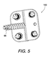
- FIGS. 1-5 illustrate various views of a calcaneal step (correction osteotomy) plate of the present invention
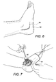
- FIGS. 6-17 illustrate a sequence of steps of a calcaneal fracture treatment (medial shift approach) with the correction osteotomy plate of the present invention.
- FIGS. 18-25 illustrate another sequence of steps of a calcaneal fracture treatment (lateral shift approach) with the correction osteotomy plate of the present invention.
- the present invention provides a bone plate (a correction osteotomy plate) that may be used in conjunction with various calcaneal repair procedures.
- the calcaneus step plate of the present invention has a stepped configuration and is provided with two vertically-spaced plate sections connected by an intermediate wall having a center sliding mechanism.
- the two vertically-spaced plate sections are about parallel to each other and the intermediate wall extends about perpendicular to them.
- the two vertically-spaced plate sections extend on opposite sides of the intermediate wall and are symmetrically positioned relative to the intermediate wall.
- Each of the two vertically spaced plate sections is provided with comer-located screw holes.
- the comer-located screw holes are preferably not configured to function as slide holes.
- An arc-shaped (arcuate) protrusion extends away from the intermediate wall.
- the arc-shaped (arcuate) protrusion may be attached to, or integral with, the intermediate wall.
- the arc-shaped (arcuate) protrusion contains an internal, truncated passageway (an arc-shaped compression hole) for a compression screw.
- the truncated passage includes an inner outlet opening smaller in cross-section than its outer, elongated inlet opening.
- the outer, elongated opening includes a ridge upon which the head of the compression screw can slide.
- the arc-shaped compression hole formed within the arcuate protrusion provides a unique center sliding mechanism that imparts compression on the counter cortex and helps with the sliding osteotomy as the tendons tend to pull back.
- the center sliding mechanism of the step plate of the invention also allows sliding of the screw in the middle (for both sliding and rotation of the compression screw) to achieve compression on the counter cortex.
- Figures 1-5 illustrate various perspective views of calcaneus step plate 100 that may be employed for calcaneal fracture repairs.
- Calcaneus step plate 100 of the present invention is provided with two vertically-spaced plate sections 10, 20 connected by an intermediate wall 30 having a unique center sliding mechanism.
- the two vertically-spaced plate sections 10, 20 are about parallel to each other and the intermediate wall 30 extends about perpendicular to each of the plate sections 10, 20 (with plate sections 10, 20 extending on opposite sides of the intermediate wall 30).
- Each of the two vertically spaced plate sections 10, 20 is provided with comer-located holes 15 (configured to accommodate fixation devices such as screws 16).
- the comer-located holes 15 are preferably not configured to function as slide holes.
- one of the two plate sections 10, 20 (for example, plate section 10 of Figure 2 ) of the plate 100 has a wedged design as opposed to the parallel design of the other of the two plate sections (for example, plate section 20 of Figure 2 ).
- An upper (top) surface 10a of the plate section 10 extends in a direction non-parallel to a lower (bottom) surface 10b, forming an angle ⁇ of about 5 to about 45 degrees.
- the other plate section 20 has an upper (top) surface 20a which extends in a direction about parallel to a lower (bottom) surface 20b.
- one of the first and second plate sections 10, 20 has a uniform height H1 and the other one of the first and second plate sections 10, 20 (for example, plate section 10) has a non-uniform (gradual) height H2 with a wedged profile.
- the special profile of the plate section 10 enables orthograde placement of the fixation device (for example, a screw) even in the case of angled bone surfaces.
- An arc-shaped (arcuate) protrusion 50 extends from the intermediate wall 30 and contains an internal sliding mechanism 55 for a compression screw 66.
- the arcuate protrusion 50 is bound by two straight walls 50a, 50b, connected by an arcuate wall 50c (as shown in Figure 2 ) which abuts sliding mechanism 55.
- the sliding mechanism 55 includes an arc-shaped compression hole 56 with an elongated opening that includes a ridge upon with the head of the compression screw 66 can slide (as detailed below with reference to Figures 6-25 ).
- the arc-shaped compression hole 56 provides a unique sliding mechanism that imparts compression on the counter cortex and helps with the sliding osteotomy as the tendons tend to pull back.
- the center sliding mechanism 55 of the step plate of the invention also allows tilting of the compression screw 66 (with both sliding and rotation of the compression screw 66) to achieve compression on the counter cortex.
- Calcaneus step plate 100 of the present invention is preferably formed of a metal such as titanium, titanium alloy, stainless steel, or other materials that possess mechanical and physical properties suitable for coupling bones together.
- the grain of the metal is oriented parallel with the longer dimension of the bone plate.
- Calcaneus step plate 100 of the present invention can be provided in various sizes depending on the anatomical size of the calcaneus to be treated.
- Figures 6-17 illustrate an exemplary sequence of steps of a calcaneal fracture treatment (undergoing the medial shift approach) with the calcaneal step plate 100 of the present invention, and according to one embodiment of the present invention.
- Figures 18-25 illustrate an exemplary sequence of steps of a calcaneal fracture treatment (the lateral shift approach) with the calcaneal step plate 100 of the present invention, and according to another embodiment of the present invention.
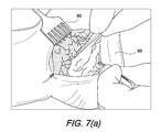
- Figures 6, 7 and 7a illustrate the formation of an incision 98 on the lateral side of ankle 99 and preparation of the bone (using a retractors 80 such as a Hohmann retractor 80, for example).
- Incision 98 is slightly curved, i.e., formed at an angle of about 90 degrees (as compared to the more straight-line incisions of the prior art) to avoid the skin scar over the osteotomy site and to better conform to the structural characteristics of the plate to be inserted.
- Figures 8 and 9 illustrate the placement of a saw template 81 (with handle 82 pointing to heel tip 99a) and the removal of the template (mating part) and the placement of the pins 73 ( Figures 8 and 9 ) into bone (calcaneus) using a hammer 75 ( Figure 9 ), for example.
- Saw template 81 is provided with a plain surface needed for placement of the sawcut (explained below) and is pinned to bone 99 with two single pins 73.
- the screw hole orientation of the plate 100 is angled to its planes, which requires: angulation of the saw template pins 73 (when completely seated, the pins 73 reach about 3 mm into the bone); and a locking drill guide perpendicular to the screw axis (i.e., requires angulation to the plate's planes and a recess in the plate that allows perpendicular mounting of the drill guide).
- a locking drill guide perpendicular to the screw axis i.e., requires angulation to the plate's planes and a recess in the plate that allows perpendicular mounting of the drill guide.
- the same 3 mm hole is enlarged by K-wires, for example, and drills that allow insertion of screws in a standard fashion.
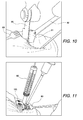
- Figures 10 and 11 illustrate sawcut 85 along the template edge through the calcaneus with the Hohmann retractor 80 to protect blood vessels and/or nerves on the medial side ( Figure 10).
- Figure 11 illustrates removal of the template 81 (using Hohmann retractors as a lever) and the placement of K-wires into prepinned holes. The locking guide allows drilling/used for orientation of screw angulation. Also shown in Figure 11 is the evaluation of the screw length with a depth measuring device 86.
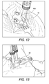
- Figures 12 and 13 illustrate insertion/placement of the locking screws 16 in the standard fashion (distal part of calcaneus (2x)) and positioning of the plate 100 in the final position (distal part to be pushed down) using a retractor (for example, a Cobra retractor) and mounted drill guides. Also shown in Figure 13 is predrilling of the compression screw hole 56 (at an angulation of about 45 degrees to bone at lower end of sliding hole).
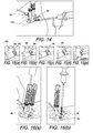
- Figures 14-16 illustrate insertion of the compression screw 66 and the advancement of the screw 66 in the compression hole 56 ( Figures 15(a)-(e)).
- Figures 14 and Figures 15(a)-(e) show the placement of the compression hole with the screw head sliding up (from Figure 15 (a) to Figure 15(e) ), adding compression to the counter cortex.
- Figures 15(a)-(e) illustrate the compression hole sliding for step plate 100, shown at various stages of compression sliding.
- Figure 16 illustrates predrilling/measuring/insertion of proximal screws 16 in a standard fashion.
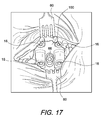
- Figure 17 illustrates plate 100 fully seated. Suturing of the surgical site may follow.
- Figures 18 and 19 illustrate the insertion of the template 81 with handle 82 pointing toward the heel tip 99a and the placement of the sawcut 85 along the template edge.
- Incision 98 is slightly curved, i.e., formed at an angle of about 90 degrees (as compared to the more straight-line incisions of the prior art) to avoid the skin scar over the osteotomy site and to better conform to the structural characteristics of the plate 100 to be inserted.
- Figures 20-22 illustrate placement of the proximal screws 16 in the standard fashion and the final positioning of the plate 100 (distal part to be pushed down) using a retractor (for example, a Cobra retractor) and mounted drill guides ( Figure 21).
- Figure 22 shows predrilling of the compression screw hole 56 towards the heel tip and the evaluation of the length of the compression screw 66 (with a depth measuring device).
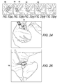
- Figures 23(a)-(e) show the insertion/sliding of the screw 66 in the compression hole 56 (at various stages of compression sliding).
- Figures 23(a)-(e) show the placement of the compression hole with the screw head sliding up (from Figure 23(a) to Figure 23(e) ), adding compression to the counter cortex.
- Figures 24 and 25 illustrate the insertion/placement of the compression screw ( Figure 24 ) and insertion of the distal screws 16 in a standard fashion ( Figure 25 ).
- the calcaneus step plate of the present invention provides the possibility of adding compression to the medial side of the calcaneus and of the osteotomy.
- the calcaneus step plate with the unique sliding mechanism may be employed to address adult flatfoot, to correct hindfoot valgus after recurrent pronation trauma and deltoid ligament insufficiency, and to correct a misaligned ankle with deformity, among many others.
- the calcaneus step plate of the present invention is a correction osteotomy plate that confers improved remodeling according to the lateral wall of the calcaneus.
- the plate is suited to the mechanical and biological characteristics of intra-articular calcaneal fracture repairs, with improved results (i.e., with reduced irritation of soft tissues and tendons, and decreased number of late complications necessitating corrective procedures occurring subsequent to the fracture treatment).
Landscapes
- Health & Medical Sciences (AREA)
- Orthopedic Medicine & Surgery (AREA)
- Surgery (AREA)
- Life Sciences & Earth Sciences (AREA)
- Heart & Thoracic Surgery (AREA)
- Veterinary Medicine (AREA)
- Engineering & Computer Science (AREA)
- Biomedical Technology (AREA)
- Nuclear Medicine, Radiotherapy & Molecular Imaging (AREA)
- Medical Informatics (AREA)
- Molecular Biology (AREA)
- Animal Behavior & Ethology (AREA)
- General Health & Medical Sciences (AREA)
- Public Health (AREA)
- Neurology (AREA)
- Dentistry (AREA)
- Oral & Maxillofacial Surgery (AREA)
- Surgical Instruments (AREA)
Abstract
Description
- The present invention relates to a novel bone plate for calcaneal fracture treatment.
- Calcaneal fractures are typically caused by a high-velocity impact to the heel (for example, a fall from a height of at least two meters or an impact as a result of a motor vehicle accident). Calcaneal fractures may be extra or intra-articular.
- One method currently used for treatment of calcaneal fractures is surgical treatment with open reduction and internal fixation, to restore the articular surface of the calcaneus and to obtain an anatomic reconstruction (height and width of the calcaneus). Although open reduction and internal fixation of intra-articular calcaneal fractures has become a standard surgical procedure with relatively low complication rate, there are still problems associated with this technique, primarily because of the complicated physical arrangement of the articular surfaces of the calcaneus (calcaneal bone). Clinical and technical problems can also occur due to the thickness and the stiffness of the plates, in particular superficial necrosis of the surgical wounds and peroneal tendonitis. These problems are related to the traction onto the skin flap during surgery and to the thickness of the plates that may cause ischemic problems to the skin and impingement of the peroneal tendons.
- In addition, most plates have a limited number of holes and do not allow for significant molding because of their thickness. In this situation, the screws have to be inserted in predetermined sites of the calcaneal wall, and especially in the fractured zones of the lateral calcaneal wall, in the small fractures. Sometimes, this can lead to insufficient grip of the screws and therefore insufficient mechanical resistance of the implant. In those circumstances, early movement to prevent joint stiffness and enhance fractured soft tissue healing is not possible.
- Accordingly, there is a need for better compression and load distribution between the articular surfaces of a fractured calcaneus, with increased stability by locking screw fixation and bridging of the fracture line. A plate with a step configuration that confers improved remodeling according to the lateral wall of the calcaneus and that is suited to the mechanical and biological characteristics of the method (open reduction and internal fixation) of intra-articular calcaneal fractures, with improved results, is also needed. A calcaneus correction osteotomy plate that reduces irritation of soft tissues and tendons, and decreases the number of late complications necessitating corrective procedures occurring subsequent to the fracture treatment, is also needed.
- The present invention provides a calcaneus plate (a correction osteotomy plate) provided with two vertically-spaced plate sections, with comer-located screw holes. An intermediate wall connects the plate sections. An arc-shaped (arcuate) protrusion extends from the intermediate wall and contains an internal sliding mechanism for a compression screw. The sliding mechanism includes an arc-shaped compression hole with an elongated opening that includes a ridge upon with the compression screw head can slide.
- The arc-shaped compression hole provides a unique sliding mechanism that imparts compression on the counter cortex and helps with the sliding osteotomy as the tendons tend to pull back. The center sliding mechanism of the step plate of the invention also allows tilting of the compression screw (with both sliding and rotation of the compression screw) to achieve compression on the counter cortex.
- Other features and advantages of the present invention will become apparent from the following description of the invention, which refers to the accompanying drawings.
-
FIGS. 1-5 illustrate various views of a calcaneal step (correction osteotomy) plate of the present invention; -
FIGS. 6-17 illustrate a sequence of steps of a calcaneal fracture treatment (medial shift approach) with the correction osteotomy plate of the present invention; and -
FIGS. 18-25 illustrate another sequence of steps of a calcaneal fracture treatment (lateral shift approach) with the correction osteotomy plate of the present invention. - In the following detailed description, reference is made to various specific embodiments in which the invention may be practiced. These embodiments are described with sufficient detail to enable those skilled in the art to practice the invention, and it is to be understood that other embodiments may be employed, and that structural and logical changes may be made without departing from the spirit or scope of the present invention.
- The present invention provides a bone plate (a correction osteotomy plate) that may be used in conjunction with various calcaneal repair procedures.
- The calcaneus step plate of the present invention has a stepped configuration and is provided with two vertically-spaced plate sections connected by an intermediate wall having a center sliding mechanism. The two vertically-spaced plate sections are about parallel to each other and the intermediate wall extends about perpendicular to them. The two vertically-spaced plate sections extend on opposite sides of the intermediate wall and are symmetrically positioned relative to the intermediate wall.
- Each of the two vertically spaced plate sections is provided with comer-located screw holes. The comer-located screw holes are preferably not configured to function as slide holes.
- An arc-shaped (arcuate) protrusion extends away from the intermediate wall. The arc-shaped (arcuate) protrusion may be attached to, or integral with, the intermediate wall. The arc-shaped (arcuate) protrusion contains an internal, truncated passageway (an arc-shaped compression hole) for a compression screw. The truncated passage includes an inner outlet opening smaller in cross-section than its outer, elongated inlet opening. The outer, elongated opening includes a ridge upon which the head of the compression screw can slide.
- The arc-shaped compression hole formed within the arcuate protrusion provides a unique center sliding mechanism that imparts compression on the counter cortex and helps with the sliding osteotomy as the tendons tend to pull back. The center sliding mechanism of the step plate of the invention also allows sliding of the screw in the middle (for both sliding and rotation of the compression screw) to achieve compression on the counter cortex.
- Referring now to the drawings, where like elements are designated by like reference numerals,
Figures 1-5 illustrate various perspective views ofcalcaneus step plate 100 that may be employed for calcaneal fracture repairs. - Calcaneus
step plate 100 of the present invention is provided with two vertically-spacedplate sections intermediate wall 30 having a unique center sliding mechanism. The two vertically-spaced plate sections intermediate wall 30 extends about perpendicular to each of theplate sections 10, 20 (withplate sections - Each of the two vertically spaced
plate sections holes 15 are preferably not configured to function as slide holes. - In an exemplary embodiment only, one of the two
plate sections 10, 20 (for example,plate section 10 ofFigure 2 ) of theplate 100 has a wedged design as opposed to the parallel design of the other of the two plate sections (for example,plate section 20 ofFigure 2 ). An upper (top)surface 10a of theplate section 10 extends in a direction non-parallel to a lower (bottom)surface 10b, forming an angle α of about 5 to about 45 degrees. Theother plate section 20 has an upper (top)surface 20a which extends in a direction about parallel to a lower (bottom)surface 20b. In other words, and as shown inFigure 2 , one of the first andsecond plate sections 10, 20 (for example, plate section 20) has a uniform height H1 and the other one of the first andsecond plate sections 10, 20 (for example, plate section 10) has a non-uniform (gradual) height H2 with a wedged profile. The special profile of theplate section 10 enables orthograde placement of the fixation device (for example, a screw) even in the case of angled bone surfaces. - An arc-shaped (arcuate)
protrusion 50 extends from theintermediate wall 30 and contains aninternal sliding mechanism 55 for acompression screw 66. Thearcuate protrusion 50 is bound by twostraight walls arcuate wall 50c (as shown inFigure 2 ) which abuts slidingmechanism 55. Thesliding mechanism 55 includes an arc-shaped compression hole 56 with an elongated opening that includes a ridge upon with the head of thecompression screw 66 can slide (as detailed below with reference toFigures 6-25 ). - The arc-
shaped compression hole 56 provides a unique sliding mechanism that imparts compression on the counter cortex and helps with the sliding osteotomy as the tendons tend to pull back. Thecenter sliding mechanism 55 of the step plate of the invention also allows tilting of the compression screw 66 (with both sliding and rotation of the compression screw 66) to achieve compression on the counter cortex. - Calcaneus
step plate 100 of the present invention is preferably formed of a metal such as titanium, titanium alloy, stainless steel, or other materials that possess mechanical and physical properties suitable for coupling bones together. Preferably, the grain of the metal is oriented parallel with the longer dimension of the bone plate. Calcaneusstep plate 100 of the present invention can be provided in various sizes depending on the anatomical size of the calcaneus to be treated. -
Figures 6-17 illustrate an exemplary sequence of steps of a calcaneal fracture treatment (undergoing the medial shift approach) with thecalcaneal step plate 100 of the present invention, and according to one embodiment of the present invention.Figures 18-25 illustrate an exemplary sequence of steps of a calcaneal fracture treatment (the lateral shift approach) with thecalcaneal step plate 100 of the present invention, and according to another embodiment of the present invention. -
Figures 6-17 (medial shift) -
Figures 6, 7 and7a illustrate the formation of anincision 98 on the lateral side ofankle 99 and preparation of the bone (using aretractors 80 such as aHohmann retractor 80, for example).Incision 98 is slightly curved, i.e., formed at an angle of about 90 degrees (as compared to the more straight-line incisions of the prior art) to avoid the skin scar over the osteotomy site and to better conform to the structural characteristics of the plate to be inserted. -
Figures 8 and 9 illustrate the placement of a saw template 81 (withhandle 82 pointing toheel tip 99a) and the removal of the template (mating part) and the placement of the pins 73 (Figures 8 and 9 ) into bone (calcaneus) using a hammer 75 (Figure 9 ), for example.Saw template 81 is provided with a plain surface needed for placement of the sawcut (explained below) and is pinned tobone 99 with twosingle pins 73. As detailed below, the screw hole orientation of theplate 100 is angled to its planes, which requires: angulation of the saw template pins 73 (when completely seated, thepins 73 reach about 3 mm into the bone); and a locking drill guide perpendicular to the screw axis (i.e., requires angulation to the plate's planes and a recess in the plate that allows perpendicular mounting of the drill guide). Using this drill guide, the same 3 mm hole is enlarged by K-wires, for example, and drills that allow insertion of screws in a standard fashion. -
Figures 10 and 11 illustratesawcut 85 along the template edge through the calcaneus with theHohmann retractor 80 to protect blood vessels and/or nerves on the medial side (Figure 10). Figure 11 illustrates removal of the template 81 (using Hohmann retractors as a lever) and the placement of K-wires into prepinned holes. The locking guide allows drilling/used for orientation of screw angulation. Also shown inFigure 11 is the evaluation of the screw length with adepth measuring device 86. -
Figures 12 and 13 illustrate insertion/placement of the locking screws 16 in the standard fashion (distal part of calcaneus (2x)) and positioning of theplate 100 in the final position (distal part to be pushed down) using a retractor (for example, a Cobra retractor) and mounted drill guides. Also shown inFigure 13 is predrilling of the compression screw hole 56 (at an angulation of about 45 degrees to bone at lower end of sliding hole). -
Figures 14-16 illustrate insertion of thecompression screw 66 and the advancement of thescrew 66 in the compression hole 56 (Figures 15(a)-(e)). Figures 14 and Figures 15(a)-(e) show the placement of the compression hole with the screw head sliding up (fromFigure 15 (a) to Figure 15(e) ), adding compression to the counter cortex.Figures 15(a)-(e) illustrate the compression hole sliding forstep plate 100, shown at various stages of compression sliding.Figure 16 illustrates predrilling/measuring/insertion ofproximal screws 16 in a standard fashion. -
Figure 17 illustratesplate 100 fully seated. Suturing of the surgical site may follow. -
Figures 18-25 (lateral shift - showing only differences relative to the medial shift approach) -
Figures 18 and 19 illustrate the insertion of thetemplate 81 withhandle 82 pointing toward theheel tip 99a and the placement of thesawcut 85 along the template edge.Incision 98 is slightly curved, i.e., formed at an angle of about 90 degrees (as compared to the more straight-line incisions of the prior art) to avoid the skin scar over the osteotomy site and to better conform to the structural characteristics of theplate 100 to be inserted. -
Figures 20-22 illustrate placement of theproximal screws 16 in the standard fashion and the final positioning of the plate 100 (distal part to be pushed down) using a retractor (for example, a Cobra retractor) and mounted drill guides (Figure 21). Figure 22 shows predrilling of thecompression screw hole 56 towards the heel tip and the evaluation of the length of the compression screw 66 (with a depth measuring device). -
Figures 23(a)-(e) show the insertion/sliding of thescrew 66 in the compression hole 56 (at various stages of compression sliding).Figures 23(a)-(e) show the placement of the compression hole with the screw head sliding up (fromFigure 23(a) to Figure 23(e) ), adding compression to the counter cortex. -
Figures 24 and 25 illustrate the insertion/placement of the compression screw (Figure 24 ) and insertion of thedistal screws 16 in a standard fashion (Figure 25 ). - The calcaneus step plate of the present invention provides the possibility of adding compression to the medial side of the calcaneus and of the osteotomy. The calcaneus step plate with the unique sliding mechanism may be employed to address adult flatfoot, to correct hindfoot valgus after recurrent pronation trauma and deltoid ligament insufficiency, and to correct a misaligned ankle with deformity, among many others.
- The calcaneus step plate of the present invention is a correction osteotomy plate that confers improved remodeling according to the lateral wall of the calcaneus. The plate is suited to the mechanical and biological characteristics of intra-articular calcaneal fracture repairs, with improved results (i.e., with reduced irritation of soft tissues and tendons, and decreased number of late complications necessitating corrective procedures occurring subsequent to the fracture treatment).
- Although the present invention has been described in relation to particular embodiments thereof, many other variations and modifications and other uses will become apparent to those skilled in the art. It is preferred, therefore, that the present invention be limited not by the specific disclosure herein, but only by the appended claims.
Claims (12)
- A bone plate, comprising:a first plate section and a second plate section extending about parallel to the first plate section;an intermediate plate section connecting the first and second plate sections and extending about perpendicular to the first and second plate sections, so that the first and second plate sections are symmetrically located relative to the intermediate wall section and opposite to each other; andan arcuate protrusion extending away from the intermediate plate section and in a direction about perpendicular to the intermediate plate section, the arcuate protrusion comprising a truncated passage with a through-hole for receiving a compression fixation device.
- The bone plate of claim 1, wherein the arcuate protrusion is integral to the intermediate plate section.
- The bone plate of claim 1, wherein the arcuate protrusion is provided with a center sliding mechanism located at about a middle of the protrusion, to allow the compression fixation device to both slide and rotate therethrough to achieve compression to counter bone cortex.
- The bone plate of claim 3, wherein the compression fixation device is a compression screw.
- The bone plate of claim 3, wherein the center sliding mechanism is a truncated passage that includes an inner outlet opening and an opposing outer inlet opening, wherein a cross section of the inner outlet opening is smaller than a cross section of the outer inlet opening.
- The bone plate of claim 1, wherein one of the first and second plate sections has a wedged profile.
- The bone plate of claim 1, wherein each of the first and second plate sections is provided with a plurality of apertures passing through the first and second plate sections.
- The bone plate of claim 7, wherein each of the apertures accommodates a fixation device.
- The bone plate of claim 7, wherein each of the apertures is located in a corner of the first and second plate sections.
- The bone plate of claim 1, wherein the plate has a stepped configuration.
- The bone plate of claim 1, wherein the plate is a correction osteotomy plate employed for calcaneal repairs.
- The bone plate of claim 1, wherein the compression fixation device is a screw that slides and rotates within the through-hole of the truncated passage.
Applications Claiming Priority (1)
| Application Number | Priority Date | Filing Date | Title |
|---|---|---|---|
| US35359010P | 2010-06-10 | 2010-06-10 |
Publications (2)
| Publication Number | Publication Date |
|---|---|
| EP2394592A1 true EP2394592A1 (en) | 2011-12-14 |
| EP2394592B1 EP2394592B1 (en) | 2013-12-18 |
Family
ID=44503524
Family Applications (1)
| Application Number | Title | Priority Date | Filing Date |
|---|---|---|---|
| EP11169350.3A Active EP2394592B1 (en) | 2010-06-10 | 2011-06-09 | Calcaneus step plate |
Country Status (2)
| Country | Link |
|---|---|
| US (1) | US8764807B2 (en) |
| EP (1) | EP2394592B1 (en) |
Cited By (1)
| Publication number | Priority date | Publication date | Assignee | Title |
|---|---|---|---|---|
| CN104812320A (en) * | 2012-08-30 | 2015-07-29 | 瑞特医疗技术公司 | Implant suitable for calcaneal osteotomy |
Families Citing this family (35)
| Publication number | Priority date | Publication date | Assignee | Title |
|---|---|---|---|---|
| US6610067B2 (en) | 2000-05-01 | 2003-08-26 | Arthrosurface, Incorporated | System and method for joint resurface repair |
| US8177841B2 (en) | 2000-05-01 | 2012-05-15 | Arthrosurface Inc. | System and method for joint resurface repair |
| EP2314257B9 (en) | 2000-05-01 | 2013-02-27 | ArthroSurface, Inc. | System for joint resurface repair |
| US7914545B2 (en) | 2002-12-03 | 2011-03-29 | Arthrosurface, Inc | System and method for retrograde procedure |
| US8388624B2 (en) | 2003-02-24 | 2013-03-05 | Arthrosurface Incorporated | Trochlear resurfacing system and method |
| JP2008504107A (en) | 2004-06-28 | 2008-02-14 | アースロサーフィス・インコーポレーテッド | Joint surface replacement system |
| US7828853B2 (en) | 2004-11-22 | 2010-11-09 | Arthrosurface, Inc. | Articular surface implant and delivery system |
| AU2007332787A1 (en) | 2006-12-11 | 2008-06-19 | Arthrosurface Incorporated | Retrograde resection apparatus and method |
| WO2009111481A1 (en) | 2008-03-03 | 2009-09-11 | Arthrosurface Incorporated | Bone resurfacing system and method |
| FR2936700B1 (en) | 2008-10-02 | 2012-04-13 | Memometal Technologies | ORTHOPEDIC IMPLANT IN THE FORM OF A PLATE TO BE FIXED BETWEEN TWO BONE PARTS |
| US10945743B2 (en) | 2009-04-17 | 2021-03-16 | Arthrosurface Incorporated | Glenoid repair system and methods of use thereof |
| CA3064646C (en) | 2009-04-17 | 2023-01-03 | Arthrosurface Incorporated | Glenoid resurfacing system and method |
| WO2010121250A1 (en) | 2009-04-17 | 2010-10-21 | Arthrosurface Incorporated | Glenoid resurfacing system and method |
| BR112012022482A2 (en) | 2010-03-05 | 2016-07-19 | Arthrosurface Inc | tibial surface recomposition system and method. |
| US9066716B2 (en) | 2011-03-30 | 2015-06-30 | Arthrosurface Incorporated | Suture coil and suture sheath for tissue repair |
| US9131969B2 (en) * | 2011-06-30 | 2015-09-15 | Morgan Packard Lorio | Spinal plate and method for using same |
| EP2804565B1 (en) | 2011-12-22 | 2018-03-07 | Arthrosurface Incorporated | System for bone fixation |
| DE112013003358T5 (en) | 2012-07-03 | 2015-03-19 | Arthrosurface, Inc. | System and procedure for joint surface replacement and repair |
| FR2997292B1 (en) * | 2012-10-29 | 2014-12-12 | Biotech Ortho | PLATE OF TRANSLATION OF CALCANEUM |
| US9492200B2 (en) | 2013-04-16 | 2016-11-15 | Arthrosurface Incorporated | Suture system and method |
| US10624748B2 (en) | 2014-03-07 | 2020-04-21 | Arthrosurface Incorporated | System and method for repairing articular surfaces |
| US9931219B2 (en) | 2014-03-07 | 2018-04-03 | Arthrosurface Incorporated | Implant and anchor assembly |
| US11607319B2 (en) | 2014-03-07 | 2023-03-21 | Arthrosurface Incorporated | System and method for repairing articular surfaces |
| US9980760B2 (en) | 2014-11-19 | 2018-05-29 | Paragon 28, Inc. | Step off bone plates, systems, and methods of use |
| JP6936146B2 (en) | 2015-01-07 | 2021-09-15 | トリース メディカル コンセプツ,インコーポレイティド | Bone plate fixation system and method |
| US10245086B2 (en) | 2015-02-18 | 2019-04-02 | Treace Medical Concepts, Inc. | Bone plating kit for foot and ankle applications |
| CN107928775A (en) * | 2017-06-23 | 2018-04-20 | 大博医疗科技股份有限公司 | A kind of calcaneum lockplate applied to heel string avulsion fracture |
| CA3108761A1 (en) | 2017-08-04 | 2019-02-07 | Arthrosurface Incorporated | Multicomponent articular surface implant |
| CN108095813B (en) * | 2017-12-22 | 2021-05-11 | 皖南医学院弋矶山医院 | Internal fixing device for fixing posterior cruciate ligament insertion avulsion fracture |
| CN111683611B (en) | 2018-02-05 | 2023-12-26 | 贝斯帕环球有限责任公司 | Implants and methods for the treatment of Charcol's foot and other conditions |
| WO2020014660A1 (en) | 2018-07-12 | 2020-01-16 | Treace Medical Concepts, Inc. | Multi-diameter bone pin for installing and aligning bone fixation plate while minimizing bone damage |
| GB2609338B (en) | 2019-03-12 | 2023-06-14 | Arthrosurface Inc | Humeral and glenoid articular surface implant systems and methods |
| US11890039B1 (en) | 2019-09-13 | 2024-02-06 | Treace Medical Concepts, Inc. | Multi-diameter K-wire for orthopedic applications |
| GB2604414A (en) | 2020-09-01 | 2022-09-07 | Nextremity Solutions Inc | Bone displacement system and method |
| US12016602B2 (en) * | 2021-02-26 | 2024-06-25 | Brett J. Schaefer | MIS bunion correction system |
Citations (7)
| Publication number | Priority date | Publication date | Assignee | Title |
|---|---|---|---|---|
| US4120298A (en) * | 1976-12-06 | 1978-10-17 | Fixel Irving E | Implant to secure the greater trochanter |
| US4800874A (en) * | 1986-07-15 | 1989-01-31 | Vereinigte Edelstahlwerke A.G. | Anatomical bone plate and/or transfixion plate |
| US5364399A (en) * | 1993-02-05 | 1994-11-15 | Danek Medical, Inc. | Anterior cervical plating system |
| US20050251138A1 (en) * | 2003-10-20 | 2005-11-10 | Olevsky Boris | Bone plate and method for using bone plate |
| US20070073297A1 (en) * | 2005-09-15 | 2007-03-29 | Joseph Reynolds | Implant with integral fastener retention |
| US20100121325A1 (en) * | 2008-06-24 | 2010-05-13 | Jeff Tyber | Hybrid intramedullary fixation assembly and method of use |
| US20100217327A1 (en) * | 2009-02-24 | 2010-08-26 | Vancelette David W | Plate and system for lateral treatment of a fracture of the calcaneus |
Family Cites Families (7)
| Publication number | Priority date | Publication date | Assignee | Title |
|---|---|---|---|---|
| US4479491A (en) * | 1982-07-26 | 1984-10-30 | Martin Felix M | Intervertebral stabilization implant |
| JPH0748247Y2 (en) * | 1992-11-16 | 1995-11-08 | 株式会社タグチ | Bone joint |
| DE29614425U1 (en) * | 1996-08-22 | 1997-12-18 | Waldemar Link GmbH & Co, 22339 Hamburg | Heel bone plate |
| US8105366B2 (en) * | 2002-05-30 | 2012-01-31 | Warsaw Orthopedic, Inc. | Laminoplasty plate with flanges |
| KR20050083916A (en) * | 2002-11-19 | 2005-08-26 | 어큠드 엘엘씨 | Deformable bone plates |
| WO2006091827A2 (en) * | 2005-02-25 | 2006-08-31 | Regents Of The University Of California | Device and template for canine humeral slide osteotomy |
| US8425515B2 (en) * | 2009-10-30 | 2013-04-23 | Depuy Spine, Inc. | Bone graft loading instruments and methods of connecting a bone graft to a bone plate |
-
2011
- 2011-06-07 US US13/154,805 patent/US8764807B2/en active Active
- 2011-06-09 EP EP11169350.3A patent/EP2394592B1/en active Active
Patent Citations (7)
| Publication number | Priority date | Publication date | Assignee | Title |
|---|---|---|---|---|
| US4120298A (en) * | 1976-12-06 | 1978-10-17 | Fixel Irving E | Implant to secure the greater trochanter |
| US4800874A (en) * | 1986-07-15 | 1989-01-31 | Vereinigte Edelstahlwerke A.G. | Anatomical bone plate and/or transfixion plate |
| US5364399A (en) * | 1993-02-05 | 1994-11-15 | Danek Medical, Inc. | Anterior cervical plating system |
| US20050251138A1 (en) * | 2003-10-20 | 2005-11-10 | Olevsky Boris | Bone plate and method for using bone plate |
| US20070073297A1 (en) * | 2005-09-15 | 2007-03-29 | Joseph Reynolds | Implant with integral fastener retention |
| US20100121325A1 (en) * | 2008-06-24 | 2010-05-13 | Jeff Tyber | Hybrid intramedullary fixation assembly and method of use |
| US20100217327A1 (en) * | 2009-02-24 | 2010-08-26 | Vancelette David W | Plate and system for lateral treatment of a fracture of the calcaneus |
Cited By (2)
| Publication number | Priority date | Publication date | Assignee | Title |
|---|---|---|---|---|
| CN104812320A (en) * | 2012-08-30 | 2015-07-29 | 瑞特医疗技术公司 | Implant suitable for calcaneal osteotomy |
| CN104812320B (en) * | 2012-08-30 | 2018-04-27 | 瑞特医疗技术公司 | Implants suitable for calcaneal osteotomy |
Also Published As
| Publication number | Publication date |
|---|---|
| EP2394592B1 (en) | 2013-12-18 |
| US20110306977A1 (en) | 2011-12-15 |
| US8764807B2 (en) | 2014-07-01 |
Similar Documents
| Publication | Publication Date | Title |
|---|---|---|
| EP2394592B1 (en) | Calcaneus step plate | |
| US11864803B2 (en) | Osteotomy plate, plate driver and method for their use | |
| EP2675377B1 (en) | Orthopedic compression plate | |
| JP6148572B2 (en) | Contoured bone plate holder / impactor for fixing fractures | |
| JP7035028B2 (en) | Intramedullary implant with proximal plate and how to use it | |
| US7686808B2 (en) | Fracture fixation device and implantation jig therefor | |
| EP3318208B1 (en) | Distal radius fracture fixation plate with integrated and adjustable volar ulnar facet support | |
| US9370386B2 (en) | Plating concept for distal radial fractures | |
| EP2756814A2 (en) | Distal tibia plating system | |
| EP3646805A2 (en) | Device for fixating orthopedic injury | |
| US9050137B2 (en) | Interchangeable orthopedic blade | |
| JP2014046200A (en) | Contoured bone plate for fracture fixation having hook members and holder/impactor for same | |
| US20190076177A1 (en) | Bone stabilization systems | |
| Labrum IV et al. | Augmented intramedullary screw tension band construct for olecranon fracture reduction and fixation: a review of literature and surgical technique | |
| IL193043A (en) | Fracture fixation device and implantation jig therefor | |
| Faldini et al. | Surgical treatment of complex tibial plateau fractures by closed reduction and external fixation. A review of 32 consecutive cases operated | |
| US20250213283A1 (en) | Low Profile Fixation Screws | |
| Schipper | Percutaneous Calcaneal Osteotomies | |
| Bharadwaj | Implantology of Distal Radius and Distal Ulna Fractures | |
| Bharadwaj | Implants for Distal Radius and Distal Ulna Fractures | |
| US20100198228A1 (en) | A Jig | |
| AU2024214331A1 (en) | Minimally invasive surgery lapidus system | |
| Choudhry | Funtional Outcome of Supracondylar Fracture Femur Treated by Minimally Invasive Percutaneous Plate Osteosynthesis (Mippo) | |
| Murphy et al. | 3 Osteotomy of the Proximal Phalanx |
Legal Events
| Date | Code | Title | Description |
|---|---|---|---|
| AK | Designated contracting states |
Kind code of ref document: A1 Designated state(s): AL AT BE BG CH CY CZ DE DK EE ES FI FR GB GR HR HU IE IS IT LI LT LU LV MC MK MT NL NO PL PT RO RS SE SI SK SM TR |
|
| AX | Request for extension of the european patent |
Extension state: BA ME |
|
| PUAI | Public reference made under article 153(3) epc to a published international application that has entered the european phase |
Free format text: ORIGINAL CODE: 0009012 |
|
| 17P | Request for examination filed |
Effective date: 20120528 |
|
| RIC1 | Information provided on ipc code assigned before grant |
Ipc: A61B 17/80 20060101AFI20130618BHEP |
|
| GRAP | Despatch of communication of intention to grant a patent |
Free format text: ORIGINAL CODE: EPIDOSNIGR1 |
|
| INTG | Intention to grant announced |
Effective date: 20130801 |
|
| GRAS | Grant fee paid |
Free format text: ORIGINAL CODE: EPIDOSNIGR3 |
|
| GRAA | (expected) grant |
Free format text: ORIGINAL CODE: 0009210 |
|
| AK | Designated contracting states |
Kind code of ref document: B1 Designated state(s): AL AT BE BG CH CY CZ DE DK EE ES FI FR GB GR HR HU IE IS IT LI LT LU LV MC MK MT NL NO PL PT RO RS SE SI SK SM TR |
|
| REG | Reference to a national code |
Ref country code: GB Ref legal event code: FG4D |
|
| REG | Reference to a national code |
Ref country code: CH Ref legal event code: EP |
|
| REG | Reference to a national code |
Ref country code: AT Ref legal event code: REF Ref document number: 645209 Country of ref document: AT Kind code of ref document: T Effective date: 20140115 |
|
| REG | Reference to a national code |
Ref country code: IE Ref legal event code: FG4D |
|
| REG | Reference to a national code |
Ref country code: DE Ref legal event code: R096 Ref document number: 602011004215 Country of ref document: DE Effective date: 20140213 |
|
| REG | Reference to a national code |
Ref country code: NL Ref legal event code: VDEP Effective date: 20131218 |
|
| PG25 | Lapsed in a contracting state [announced via postgrant information from national office to epo] |
Ref country code: LT Free format text: LAPSE BECAUSE OF FAILURE TO SUBMIT A TRANSLATION OF THE DESCRIPTION OR TO PAY THE FEE WITHIN THE PRESCRIBED TIME-LIMIT Effective date: 20131218 Ref country code: HR Free format text: LAPSE BECAUSE OF FAILURE TO SUBMIT A TRANSLATION OF THE DESCRIPTION OR TO PAY THE FEE WITHIN THE PRESCRIBED TIME-LIMIT Effective date: 20131218 Ref country code: FI Free format text: LAPSE BECAUSE OF FAILURE TO SUBMIT A TRANSLATION OF THE DESCRIPTION OR TO PAY THE FEE WITHIN THE PRESCRIBED TIME-LIMIT Effective date: 20131218 Ref country code: SE Free format text: LAPSE BECAUSE OF FAILURE TO SUBMIT A TRANSLATION OF THE DESCRIPTION OR TO PAY THE FEE WITHIN THE PRESCRIBED TIME-LIMIT Effective date: 20131218 Ref country code: NO Free format text: LAPSE BECAUSE OF FAILURE TO SUBMIT A TRANSLATION OF THE DESCRIPTION OR TO PAY THE FEE WITHIN THE PRESCRIBED TIME-LIMIT Effective date: 20140318 |
|
| REG | Reference to a national code |
Ref country code: LT Ref legal event code: MG4D |
|
| PG25 | Lapsed in a contracting state [announced via postgrant information from national office to epo] |
Ref country code: RS Free format text: LAPSE BECAUSE OF FAILURE TO SUBMIT A TRANSLATION OF THE DESCRIPTION OR TO PAY THE FEE WITHIN THE PRESCRIBED TIME-LIMIT Effective date: 20131218 Ref country code: LV Free format text: LAPSE BECAUSE OF FAILURE TO SUBMIT A TRANSLATION OF THE DESCRIPTION OR TO PAY THE FEE WITHIN THE PRESCRIBED TIME-LIMIT Effective date: 20131218 |
|
| PG25 | Lapsed in a contracting state [announced via postgrant information from national office to epo] |
Ref country code: EE Free format text: LAPSE BECAUSE OF FAILURE TO SUBMIT A TRANSLATION OF THE DESCRIPTION OR TO PAY THE FEE WITHIN THE PRESCRIBED TIME-LIMIT Effective date: 20131218 Ref country code: IS Free format text: LAPSE BECAUSE OF FAILURE TO SUBMIT A TRANSLATION OF THE DESCRIPTION OR TO PAY THE FEE WITHIN THE PRESCRIBED TIME-LIMIT Effective date: 20140418 |
|
| PG25 | Lapsed in a contracting state [announced via postgrant information from national office to epo] |
Ref country code: RO Free format text: LAPSE BECAUSE OF FAILURE TO SUBMIT A TRANSLATION OF THE DESCRIPTION OR TO PAY THE FEE WITHIN THE PRESCRIBED TIME-LIMIT Effective date: 20131218 Ref country code: PL Free format text: LAPSE BECAUSE OF FAILURE TO SUBMIT A TRANSLATION OF THE DESCRIPTION OR TO PAY THE FEE WITHIN THE PRESCRIBED TIME-LIMIT Effective date: 20131218 Ref country code: SK Free format text: LAPSE BECAUSE OF FAILURE TO SUBMIT A TRANSLATION OF THE DESCRIPTION OR TO PAY THE FEE WITHIN THE PRESCRIBED TIME-LIMIT Effective date: 20131218 Ref country code: NL Free format text: LAPSE BECAUSE OF FAILURE TO SUBMIT A TRANSLATION OF THE DESCRIPTION OR TO PAY THE FEE WITHIN THE PRESCRIBED TIME-LIMIT Effective date: 20131218 Ref country code: PT Free format text: LAPSE BECAUSE OF FAILURE TO SUBMIT A TRANSLATION OF THE DESCRIPTION OR TO PAY THE FEE WITHIN THE PRESCRIBED TIME-LIMIT Effective date: 20140418 Ref country code: CY Free format text: LAPSE BECAUSE OF FAILURE TO SUBMIT A TRANSLATION OF THE DESCRIPTION OR TO PAY THE FEE WITHIN THE PRESCRIBED TIME-LIMIT Effective date: 20131218 Ref country code: CZ Free format text: LAPSE BECAUSE OF FAILURE TO SUBMIT A TRANSLATION OF THE DESCRIPTION OR TO PAY THE FEE WITHIN THE PRESCRIBED TIME-LIMIT Effective date: 20131218 Ref country code: ES Free format text: LAPSE BECAUSE OF FAILURE TO SUBMIT A TRANSLATION OF THE DESCRIPTION OR TO PAY THE FEE WITHIN THE PRESCRIBED TIME-LIMIT Effective date: 20131218 |
|
| REG | Reference to a national code |
Ref country code: DE Ref legal event code: R097 Ref document number: 602011004215 Country of ref document: DE |
|
| PLBE | No opposition filed within time limit |
Free format text: ORIGINAL CODE: 0009261 |
|
| STAA | Information on the status of an ep patent application or granted ep patent |
Free format text: STATUS: NO OPPOSITION FILED WITHIN TIME LIMIT |
|
| PG25 | Lapsed in a contracting state [announced via postgrant information from national office to epo] |
Ref country code: DK Free format text: LAPSE BECAUSE OF FAILURE TO SUBMIT A TRANSLATION OF THE DESCRIPTION OR TO PAY THE FEE WITHIN THE PRESCRIBED TIME-LIMIT Effective date: 20131218 |
|
| 26N | No opposition filed |
Effective date: 20140919 |
|
| REG | Reference to a national code |
Ref country code: DE Ref legal event code: R097 Ref document number: 602011004215 Country of ref document: DE Effective date: 20140919 |
|
| PG25 | Lapsed in a contracting state [announced via postgrant information from national office to epo] |
Ref country code: LU Free format text: LAPSE BECAUSE OF FAILURE TO SUBMIT A TRANSLATION OF THE DESCRIPTION OR TO PAY THE FEE WITHIN THE PRESCRIBED TIME-LIMIT Effective date: 20140609 Ref country code: MC Free format text: LAPSE BECAUSE OF FAILURE TO SUBMIT A TRANSLATION OF THE DESCRIPTION OR TO PAY THE FEE WITHIN THE PRESCRIBED TIME-LIMIT Effective date: 20131218 |
|
| REG | Reference to a national code |
Ref country code: CH Ref legal event code: PL |
|
| REG | Reference to a national code |
Ref country code: IE Ref legal event code: MM4A |
|
| PG25 | Lapsed in a contracting state [announced via postgrant information from national office to epo] |
Ref country code: CH Free format text: LAPSE BECAUSE OF NON-PAYMENT OF DUE FEES Effective date: 20140630 Ref country code: IE Free format text: LAPSE BECAUSE OF NON-PAYMENT OF DUE FEES Effective date: 20140609 Ref country code: LI Free format text: LAPSE BECAUSE OF NON-PAYMENT OF DUE FEES Effective date: 20140630 |
|
| PG25 | Lapsed in a contracting state [announced via postgrant information from national office to epo] |
Ref country code: SI Free format text: LAPSE BECAUSE OF FAILURE TO SUBMIT A TRANSLATION OF THE DESCRIPTION OR TO PAY THE FEE WITHIN THE PRESCRIBED TIME-LIMIT Effective date: 20131218 |
|
| PG25 | Lapsed in a contracting state [announced via postgrant information from national office to epo] |
Ref country code: MT Free format text: LAPSE BECAUSE OF FAILURE TO SUBMIT A TRANSLATION OF THE DESCRIPTION OR TO PAY THE FEE WITHIN THE PRESCRIBED TIME-LIMIT Effective date: 20131218 |
|
| PG25 | Lapsed in a contracting state [announced via postgrant information from national office to epo] |
Ref country code: SM Free format text: LAPSE BECAUSE OF FAILURE TO SUBMIT A TRANSLATION OF THE DESCRIPTION OR TO PAY THE FEE WITHIN THE PRESCRIBED TIME-LIMIT Effective date: 20131218 |
|
| REG | Reference to a national code |
Ref country code: FR Ref legal event code: PLFP Year of fee payment: 6 |
|
| PG25 | Lapsed in a contracting state [announced via postgrant information from national office to epo] |
Ref country code: GR Free format text: LAPSE BECAUSE OF FAILURE TO SUBMIT A TRANSLATION OF THE DESCRIPTION OR TO PAY THE FEE WITHIN THE PRESCRIBED TIME-LIMIT Effective date: 20140319 Ref country code: BG Free format text: LAPSE BECAUSE OF FAILURE TO SUBMIT A TRANSLATION OF THE DESCRIPTION OR TO PAY THE FEE WITHIN THE PRESCRIBED TIME-LIMIT Effective date: 20131218 |
|
| PG25 | Lapsed in a contracting state [announced via postgrant information from national office to epo] |
Ref country code: TR Free format text: LAPSE BECAUSE OF FAILURE TO SUBMIT A TRANSLATION OF THE DESCRIPTION OR TO PAY THE FEE WITHIN THE PRESCRIBED TIME-LIMIT Effective date: 20131218 Ref country code: HU Free format text: LAPSE BECAUSE OF FAILURE TO SUBMIT A TRANSLATION OF THE DESCRIPTION OR TO PAY THE FEE WITHIN THE PRESCRIBED TIME-LIMIT; INVALID AB INITIO Effective date: 20110609 |
|
| REG | Reference to a national code |
Ref country code: FR Ref legal event code: PLFP Year of fee payment: 7 |
|
| REG | Reference to a national code |
Ref country code: FR Ref legal event code: PLFP Year of fee payment: 8 |
|
| PG25 | Lapsed in a contracting state [announced via postgrant information from national office to epo] |
Ref country code: MK Free format text: LAPSE BECAUSE OF FAILURE TO SUBMIT A TRANSLATION OF THE DESCRIPTION OR TO PAY THE FEE WITHIN THE PRESCRIBED TIME-LIMIT Effective date: 20131218 |
|
| PG25 | Lapsed in a contracting state [announced via postgrant information from national office to epo] |
Ref country code: AL Free format text: LAPSE BECAUSE OF FAILURE TO SUBMIT A TRANSLATION OF THE DESCRIPTION OR TO PAY THE FEE WITHIN THE PRESCRIBED TIME-LIMIT Effective date: 20131218 |
|
| PGFP | Annual fee paid to national office [announced via postgrant information from national office to epo] |
Ref country code: BE Payment date: 20200515 Year of fee payment: 10 |
|
| PGFP | Annual fee paid to national office [announced via postgrant information from national office to epo] |
Ref country code: AT Payment date: 20200526 Year of fee payment: 10 |
|
| REG | Reference to a national code |
Ref country code: AT Ref legal event code: MM01 Ref document number: 645209 Country of ref document: AT Kind code of ref document: T Effective date: 20210609 |
|
| REG | Reference to a national code |
Ref country code: BE Ref legal event code: MM Effective date: 20210630 |
|
| PG25 | Lapsed in a contracting state [announced via postgrant information from national office to epo] |
Ref country code: AT Free format text: LAPSE BECAUSE OF NON-PAYMENT OF DUE FEES Effective date: 20210609 |
|
| PG25 | Lapsed in a contracting state [announced via postgrant information from national office to epo] |
Ref country code: BE Free format text: LAPSE BECAUSE OF NON-PAYMENT OF DUE FEES Effective date: 20210630 |
|
| REG | Reference to a national code |
Ref country code: FR Ref legal event code: PLFP Year of fee payment: 13 |
|
| PGFP | Annual fee paid to national office [announced via postgrant information from national office to epo] |
Ref country code: DE Payment date: 20250402 Year of fee payment: 15 |
|
| PGFP | Annual fee paid to national office [announced via postgrant information from national office to epo] |
Ref country code: GB Payment date: 20250401 Year of fee payment: 15 |
|
| PGFP | Annual fee paid to national office [announced via postgrant information from national office to epo] |
Ref country code: IT Payment date: 20250522 Year of fee payment: 15 |
|
| PGFP | Annual fee paid to national office [announced via postgrant information from national office to epo] |
Ref country code: FR Payment date: 20250401 Year of fee payment: 15 |