EP2393263A1 - Electronic device - Google Patents
Electronic device Download PDFInfo
- Publication number
- EP2393263A1 EP2393263A1 EP11151540A EP11151540A EP2393263A1 EP 2393263 A1 EP2393263 A1 EP 2393263A1 EP 11151540 A EP11151540 A EP 11151540A EP 11151540 A EP11151540 A EP 11151540A EP 2393263 A1 EP2393263 A1 EP 2393263A1
- Authority
- EP
- European Patent Office
- Prior art keywords
- stopper
- main body
- electronic device
- cover
- battery
- Prior art date
- Legal status (The legal status is an assumption and is not a legal conclusion. Google has not performed a legal analysis and makes no representation as to the accuracy of the status listed.)
- Granted
Links
- 239000000463 material Substances 0.000 claims description 3
- 238000012986 modification Methods 0.000 description 2
- 230000004048 modification Effects 0.000 description 2
- 238000010586 diagram Methods 0.000 description 1
Images



Classifications
-
- H—ELECTRICITY
- H04—ELECTRIC COMMUNICATION TECHNIQUE
- H04M—TELEPHONIC COMMUNICATION
- H04M1/00—Substation equipment, e.g. for use by subscribers
- H04M1/02—Constructional features of telephone sets
- H04M1/0202—Portable telephone sets, e.g. cordless phones, mobile phones or bar type handsets
- H04M1/026—Details of the structure or mounting of specific components
- H04M1/0262—Details of the structure or mounting of specific components for a battery compartment
Definitions
- This application relates in general to an electronic device and in particular to an electronic device preventing from instant power-off.
- Conventional portable electronic device such as mobile phones or smart phones, usually comprises a chargeable battery therein.
- the user When replacing the battery, the user has to detach a back cover from the portable electronic device in advance.
- the battery may fall off and cause functional failure due to instant power-off when the back cover is removed.
- the mechanical design of electronic devices has become a critical issue.
- This application provides an electronic device, including a main body, a battery detachably received in the main body, a stopper disposed in a predetermined position to restrict the battery in the main body, an antenna disposed on the stopper, and a cover connected with the stopper and movable relative to the stopper between a first position and a second position.
- the cover When the cover is in the first position, the cover is engaged with the main body and restricts the stopper in the predetermined position.
- the cover is moved from the first position along a first direction to the second position, the cover is disengaged from the main body, and the stopper is releasable from the predetermined position along a second direction.
- FIG. 1 is a perspective diagram of an electronic device according to an embodiment of the invention.
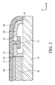
- FIG. 2 is a sectional view of an electronic device when in normal use according to an embodiment of the invention.
- FIG. 3 is a sectional view of a cover sliding to a second position relative to a stopper of an electronic device according to an embodiment of the invention.
- FIG. 4 is a sectional view of a cover and a stopper detached from a main body of an electronic device according to an embodiment of the invention.
- an embodiment of an electronic device primarily comprises a main body 10, a stopper 20, a cover 30, and an antenna A embedded on the stopper 20, and a battery B detachably received in the main body 10.
- the stopper 20 and the cover 30 comprise plastic material and are movably connected with each other.
- the stopper 20 forms two protrusions 22, and the main body 10 forms a recess R with two slots R on opposite sides thereof.
- the stopper 20 is disposed in a predetermined position of the recess R with the protrusions 22 respectively positioned in the slots R. It is noted the stopper 20 is restricted in the recess R and cannot move along the X direction (first direction).
- the cover 30 when the electronic device is assembled for normal usage, the cover 30 is situated in a first position above the stopper 20.
- a first joining portion J1 of the main body 10 is engaged with a second joining portion J2 of the cover 30, so as to restrict the stopper 20 in the predetermined position of the recess R.
- a sliding portion 31 of the cover 30 is disposed through a hole 21 of the stopper 20, wherein the stopper 20 abuts the battery B to prevent the battery B from popping out of the main body 10 through the opening 11.
- the cover 30 Before releasing the battery B, as shown in FIG. 3 , the cover 30 is pulled out relative to the stopper 20 along the X direction.
- a sensor S on the main body 10 can transmit an electrical signal to a processing circuit in the main body 10 when detecting that the cover 30 has separated from the main body 10.
- the electronic device can be timely shut off.
- the sliding portion 31 of the cover 30 moves in the hole 21, and the first and second joining portions J1 and J2 are separated from each other, such that the cover 30 is released from the main body 10.
- the stopper 20 keeps in contact with the battery B along the X direction, so as to prevent the battery B from popping out of the main body 10 through the opening 11.
- the cover 30 and the stopper 20 can be removed from the main body 10 along the Z direction (second direction).
- the sliding portion 31 of the cover 30 through the stopper 20 has a T-shaped cross-section. Since the sliding portion 31 is fastened through the stopper 20, the stopper 20 can be removed with the cover 30 to be released from the recess R, as shown in FIG. 4 .
- the battery B can be taken out of the main body 10 through the opening 11.
Landscapes
- Engineering & Computer Science (AREA)
- Signal Processing (AREA)
- Telephone Set Structure (AREA)
- Casings For Electric Apparatus (AREA)
- Battery Mounting, Suspending (AREA)
Abstract
Description
- This Application claims priority of Taiwan Patent Application No.
099117548, filed on June. 1, 2010 - This application relates in general to an electronic device and in particular to an electronic device preventing from instant power-off.
- Conventional portable electronic device, such as mobile phones or smart phones, usually comprises a chargeable battery therein. When replacing the battery, the user has to detach a back cover from the portable electronic device in advance. However, the battery may fall off and cause functional failure due to instant power-off when the back cover is removed. To solve the aforesaid problem, the mechanical design of electronic devices has become a critical issue.
- This application provides an electronic device, including a main body, a battery detachably received in the main body, a stopper disposed in a predetermined position to restrict the battery in the main body, an antenna disposed on the stopper, and a cover connected with the stopper and movable relative to the stopper between a first position and a second position. When the cover is in the first position, the cover is engaged with the main body and restricts the stopper in the predetermined position. When the cover is moved from the first position along a first direction to the second position, the cover is disengaged from the main body, and the stopper is releasable from the predetermined position along a second direction.
- The invention can be more fully understood by reading the subsequent detailed description and examples with references made to the accompanying drawings, wherein:
-
FIG. 1 is a perspective diagram of an electronic device according to an embodiment of the invention; -
FIG. 2 is a sectional view of an electronic device when in normal use according to an embodiment of the invention; -
FIG. 3 is a sectional view of a cover sliding to a second position relative to a stopper of an electronic device according to an embodiment of the invention; and -
FIG. 4 is a sectional view of a cover and a stopper detached from a main body of an electronic device according to an embodiment of the invention. - Referring to
FIG. 1 , an embodiment of an electronic device, such as mobile phones or smart phones, primarily comprises amain body 10, astopper 20, acover 30, and an antenna A embedded on thestopper 20, and a battery B detachably received in themain body 10. In this embodiment, thestopper 20 and thecover 30 comprise plastic material and are movably connected with each other. As shown inFIG. 1 , thestopper 20 forms twoprotrusions 22, and themain body 10 forms a recess R with two slots R on opposite sides thereof. During assembly, thestopper 20 is disposed in a predetermined position of the recess R with theprotrusions 22 respectively positioned in the slots R. It is noted thestopper 20 is restricted in the recess R and cannot move along the X direction (first direction). - Referring to
FIG. 2 , when the electronic device is assembled for normal usage, thecover 30 is situated in a first position above thestopper 20. Here, a first joining portion J1 of themain body 10 is engaged with a second joining portion J2 of thecover 30, so as to restrict thestopper 20 in the predetermined position of the recess R. As shown inFIG. 2 , asliding portion 31 of thecover 30 is disposed through ahole 21 of thestopper 20, wherein thestopper 20 abuts the battery B to prevent the battery B from popping out of themain body 10 through theopening 11. - Before releasing the battery B, as shown in
FIG. 3 , thecover 30 is pulled out relative to thestopper 20 along the X direction. A sensor S on themain body 10 can transmit an electrical signal to a processing circuit in themain body 10 when detecting that thecover 30 has separated from themain body 10. Thus, the electronic device can be timely shut off. During sliding of thecover 30 relative to thestopper 20 from the first position to a second position, as shown inFIG. 3 , thesliding portion 31 of thecover 30 moves in thehole 21, and the first and second joining portions J1 and J2 are separated from each other, such that thecover 30 is released from themain body 10. In this state, thestopper 20 keeps in contact with the battery B along the X direction, so as to prevent the battery B from popping out of themain body 10 through theopening 11. - Referring to
FIG. 4 , as thecover 30 slides relative to thestopper 20 to the second position, thecover 30 and thestopper 20 can be removed from themain body 10 along the Z direction (second direction). In this embodiment, thesliding portion 31 of thecover 30 through thestopper 20 has a T-shaped cross-section. Since thesliding portion 31 is fastened through thestopper 20, thestopper 20 can be removed with thecover 30 to be released from the recess R, as shown inFIG. 4 . When thestopper 20 and thecover 30 are detached from themain body 10, the battery B can be taken out of themain body 10 through theopening 11. - In the state of
FIG. 3 , as the battery B is still blocked by thestopper 20 and held in themain body 10 when thecover 30 slides to the second position, the electronic device will not lose power and instantly cause functional failure. Furthermore, since the antenna A is disposed on thestopper 20 instead of themain body 10, as shown inFIG. 1 , space within themain body 10 can be saved for accommodating other interior components. - While the invention has been described by way of example and in terms of preferred embodiment, it is to be understood that the invention is not limited thereto. To the contrary, it is intended to cover various modifications and similar arrangements (as would be apparent to those skilled in the art). Therefore, the scope of the appended claims should be accorded the broadest interpretation to encompass all such modifications and similar arrangements.
Claims (10)
- An electronic device, comprising:a main body;a battery, detachably received in the main body;a stopper, disposed in a predetermined position on the main body to restrict the battery in the main body;an antenna, disposed on the stopper; anda cover, connected with the stopper and movable relative to the stopper between a first position and a second position, wherein when the cover is in the first position, the cover is engaged with the main body and restricts the stopper in the predetermined position,wherein when the cover is moved relative to the stopper from the first position along a first direction to the second position, the cover is disengaged from the main body, and the stopper is releasable from the predetermined position along a second direction.
- The electronic device as claimed in claim 1, wherein the stopper has a hole, and the cover has a sliding portion movably disposed through the hole.
- The electronic device as claimed in claim 2, wherein the sliding portion has a T-shaped cross-section.
- The electronic device as claimed in claim 1, wherein the second direction is perpendicular to the first direction.
- The electronic device as claimed in claim 1, wherein the electronic device further comprises a sensor disposed on the main body, and wherein the sensor transmits an electric signal to the main body to power-off the electronic device when the cover slides to the second position with respect to the stopper.
- The electronic device as claimed in claim 1, wherein the main body has an opening; wherein when the stopper is released from the predetermined position, the battery is released from the main body through the opening.
- The electronic device as claimed in claim 1, wherein the main body has a recess, and the stopper is received in the recess and contacts the battery to prevent the battery from being released from the main body.
- The electronic device as claimed in claim 1, wherein the recess has a slot, and the stopper has a protrusion engaged in the slot to prevent the stopper from moving along the first direction.
- The electronic device as claimed in claim 1, wherein the stopper comprises plastic material.
- The electronic device as claimed in claim 1, wherein the cover comprises plastic material.
Applications Claiming Priority (1)
| Application Number | Priority Date | Filing Date | Title |
|---|---|---|---|
| TW099117548A TWI397800B (en) | 2010-06-01 | 2010-06-01 | Electronic device |
Publications (2)
| Publication Number | Publication Date |
|---|---|
| EP2393263A1 true EP2393263A1 (en) | 2011-12-07 |
| EP2393263B1 EP2393263B1 (en) | 2013-03-27 |
Family
ID=43757891
Family Applications (1)
| Application Number | Title | Priority Date | Filing Date |
|---|---|---|---|
| EP11151540A Not-in-force EP2393263B1 (en) | 2010-06-01 | 2011-01-20 | Electronic device |
Country Status (3)
| Country | Link |
|---|---|
| US (1) | US8531339B2 (en) |
| EP (1) | EP2393263B1 (en) |
| TW (1) | TWI397800B (en) |
Cited By (1)
| Publication number | Priority date | Publication date | Assignee | Title |
|---|---|---|---|---|
| EP2632121A1 (en) * | 2012-02-23 | 2013-08-28 | Samsung Electronics Co., Ltd | Portable Terminal |
Families Citing this family (2)
| Publication number | Priority date | Publication date | Assignee | Title |
|---|---|---|---|---|
| KR101334812B1 (en) | 2011-04-14 | 2013-11-28 | 삼성전자주식회사 | Antenna device for portable terminal |
| KR102309066B1 (en) * | 2014-10-08 | 2021-10-06 | 삼성전자 주식회사 | Electronic device and antenna apparatus thereof |
Citations (1)
| Publication number | Priority date | Publication date | Assignee | Title |
|---|---|---|---|---|
| US20090005117A1 (en) * | 2007-06-27 | 2009-01-01 | Oded Bashan | Contactless smart SIM |
Family Cites Families (8)
| Publication number | Priority date | Publication date | Assignee | Title |
|---|---|---|---|---|
| TWM265773U (en) * | 2004-10-18 | 2005-05-21 | E Ten Information Sys Co Ltd | Electronic device with data protection and fixed battery cover |
| US7333062B2 (en) * | 2005-09-15 | 2008-02-19 | Motorola, Inc. | Wireless communication device with integrated antenna |
| TWI354890B (en) * | 2007-01-18 | 2011-12-21 | Askey Computer Corp | Portable electronic device with a function of dete |
| CN101291153A (en) | 2007-04-16 | 2008-10-22 | 明基电通股份有限公司 | portable electronic device |
| KR101044994B1 (en) * | 2008-06-20 | 2011-06-29 | 삼성전자주식회사 | Antenna device of mobile terminal |
| WO2010015365A2 (en) * | 2008-08-04 | 2010-02-11 | Fractus, S.A. | Antennaless wireless device |
| TWI366379B (en) * | 2008-10-30 | 2012-06-11 | Inventec Corp | Electronic apparatus with casing module |
| US8471768B2 (en) * | 2009-12-22 | 2013-06-25 | Nokia Corporation | Method and apparatus for an antenna |
-
2010
- 2010-06-01 TW TW099117548A patent/TWI397800B/en not_active IP Right Cessation
-
2011
- 2011-01-20 EP EP11151540A patent/EP2393263B1/en not_active Not-in-force
- 2011-01-28 US US13/015,881 patent/US8531339B2/en not_active Expired - Fee Related
Patent Citations (1)
| Publication number | Priority date | Publication date | Assignee | Title |
|---|---|---|---|---|
| US20090005117A1 (en) * | 2007-06-27 | 2009-01-01 | Oded Bashan | Contactless smart SIM |
Cited By (2)
| Publication number | Priority date | Publication date | Assignee | Title |
|---|---|---|---|---|
| EP2632121A1 (en) * | 2012-02-23 | 2013-08-28 | Samsung Electronics Co., Ltd | Portable Terminal |
| US9356337B2 (en) | 2012-02-23 | 2016-05-31 | Samsung Electronics Co., Ltd. | Portable terminal |
Also Published As
| Publication number | Publication date |
|---|---|
| US20110291897A1 (en) | 2011-12-01 |
| EP2393263B1 (en) | 2013-03-27 |
| TWI397800B (en) | 2013-06-01 |
| TW201144975A (en) | 2011-12-16 |
| US8531339B2 (en) | 2013-09-10 |
Similar Documents
| Publication | Publication Date | Title |
|---|---|---|
| US9387647B2 (en) | Electronic device and dust cover thereof | |
| CN107368149B (en) | Connector assembly for electronic device | |
| US7988454B1 (en) | Card connector assembly for portable electronic device | |
| US8360485B2 (en) | Holding mechanism and electronic device using the same | |
| CN108615989B (en) | Card holder assembly, electronic device and control method thereof | |
| KR102359957B1 (en) | Electronic device | |
| US20150171386A1 (en) | Battery pack | |
| US20090237892A1 (en) | Housing assembly for electronic device | |
| EP3010154B1 (en) | A system for installing removable external component in electronic devices | |
| US7131871B1 (en) | Chip card retaining mechanism | |
| CN108471009B (en) | Card holder assembly, electronic device and control method thereof | |
| US8089011B2 (en) | Control mechanism and electronic device using the same | |
| CN108615992B (en) | Card seat assembly and electronic device | |
| US8598479B2 (en) | Electronic device with push button | |
| US9136622B2 (en) | Extraction device for memory card | |
| KR20090042591A (en) | Battery fixing structure of electronic device and electronic device having same | |
| JP2011081958A (en) | Electronic device | |
| US8531339B2 (en) | Hand-held electronic device | |
| US8491320B2 (en) | Portable electronic device with chip card ejecting mechanism | |
| CN108540156B (en) | Card Holder Assembly and Electronic Device | |
| EP2154756A1 (en) | Electronic device and receptable connector thereof | |
| CN210183362U (en) | mobile terminal | |
| JP6148833B2 (en) | Battery holder and electronic device having the same | |
| US20160116945A1 (en) | Electronic device with storable keyboard | |
| JP2011222314A (en) | Card mounting device and electronic device |
Legal Events
| Date | Code | Title | Description |
|---|---|---|---|
| 17P | Request for examination filed |
Effective date: 20110121 |
|
| AK | Designated contracting states |
Kind code of ref document: A1 Designated state(s): AL AT BE BG CH CY CZ DE DK EE ES FI FR GB GR HR HU IE IS IT LI LT LU LV MC MK MT NL NO PL PT RO RS SE SI SK SM TR |
|
| AX | Request for extension of the european patent |
Extension state: BA ME |
|
| PUAI | Public reference made under article 153(3) epc to a published international application that has entered the european phase |
Free format text: ORIGINAL CODE: 0009012 |
|
| GRAP | Despatch of communication of intention to grant a patent |
Free format text: ORIGINAL CODE: EPIDOSNIGR1 |
|
| GRAS | Grant fee paid |
Free format text: ORIGINAL CODE: EPIDOSNIGR3 |
|
| GRAA | (expected) grant |
Free format text: ORIGINAL CODE: 0009210 |
|
| AK | Designated contracting states |
Kind code of ref document: B1 Designated state(s): AL AT BE BG CH CY CZ DE DK EE ES FI FR GB GR HR HU IE IS IT LI LT LU LV MC MK MT NL NO PL PT RO RS SE SI SK SM TR |
|
| REG | Reference to a national code |
Ref country code: GB Ref legal event code: FG4D |
|
| REG | Reference to a national code |
Ref country code: CH Ref legal event code: EP |
|
| REG | Reference to a national code |
Ref country code: AT Ref legal event code: REF Ref document number: 604036 Country of ref document: AT Kind code of ref document: T Effective date: 20130415 |
|
| REG | Reference to a national code |
Ref country code: IE Ref legal event code: FG4D |
|
| REG | Reference to a national code |
Ref country code: DE Ref legal event code: R096 Ref document number: 602011001133 Country of ref document: DE Effective date: 20130529 |
|
| PG25 | Lapsed in a contracting state [announced via postgrant information from national office to epo] |
Ref country code: LT Free format text: LAPSE BECAUSE OF FAILURE TO SUBMIT A TRANSLATION OF THE DESCRIPTION OR TO PAY THE FEE WITHIN THE PRESCRIBED TIME-LIMIT Effective date: 20130327 Ref country code: SE Free format text: LAPSE BECAUSE OF FAILURE TO SUBMIT A TRANSLATION OF THE DESCRIPTION OR TO PAY THE FEE WITHIN THE PRESCRIBED TIME-LIMIT Effective date: 20130327 Ref country code: NO Free format text: LAPSE BECAUSE OF FAILURE TO SUBMIT A TRANSLATION OF THE DESCRIPTION OR TO PAY THE FEE WITHIN THE PRESCRIBED TIME-LIMIT Effective date: 20130627 Ref country code: BG Free format text: LAPSE BECAUSE OF FAILURE TO SUBMIT A TRANSLATION OF THE DESCRIPTION OR TO PAY THE FEE WITHIN THE PRESCRIBED TIME-LIMIT Effective date: 20130627 |
|
| REG | Reference to a national code |
Ref country code: AT Ref legal event code: MK05 Ref document number: 604036 Country of ref document: AT Kind code of ref document: T Effective date: 20130327 |
|
| REG | Reference to a national code |
Ref country code: LT Ref legal event code: MG4D |
|
| REG | Reference to a national code |
Ref country code: NL Ref legal event code: T3 |
|
| PG25 | Lapsed in a contracting state [announced via postgrant information from national office to epo] |
Ref country code: LV Free format text: LAPSE BECAUSE OF FAILURE TO SUBMIT A TRANSLATION OF THE DESCRIPTION OR TO PAY THE FEE WITHIN THE PRESCRIBED TIME-LIMIT Effective date: 20130327 Ref country code: FI Free format text: LAPSE BECAUSE OF FAILURE TO SUBMIT A TRANSLATION OF THE DESCRIPTION OR TO PAY THE FEE WITHIN THE PRESCRIBED TIME-LIMIT Effective date: 20130327 Ref country code: SI Free format text: LAPSE BECAUSE OF FAILURE TO SUBMIT A TRANSLATION OF THE DESCRIPTION OR TO PAY THE FEE WITHIN THE PRESCRIBED TIME-LIMIT Effective date: 20130327 Ref country code: GR Free format text: LAPSE BECAUSE OF FAILURE TO SUBMIT A TRANSLATION OF THE DESCRIPTION OR TO PAY THE FEE WITHIN THE PRESCRIBED TIME-LIMIT Effective date: 20130628 |
|
| PG25 | Lapsed in a contracting state [announced via postgrant information from national office to epo] |
Ref country code: BE Free format text: LAPSE BECAUSE OF FAILURE TO SUBMIT A TRANSLATION OF THE DESCRIPTION OR TO PAY THE FEE WITHIN THE PRESCRIBED TIME-LIMIT Effective date: 20130327 Ref country code: HR Free format text: LAPSE BECAUSE OF FAILURE TO SUBMIT A TRANSLATION OF THE DESCRIPTION OR TO PAY THE FEE WITHIN THE PRESCRIBED TIME-LIMIT Effective date: 20130327 |
|
| PG25 | Lapsed in a contracting state [announced via postgrant information from national office to epo] |
Ref country code: IS Free format text: LAPSE BECAUSE OF FAILURE TO SUBMIT A TRANSLATION OF THE DESCRIPTION OR TO PAY THE FEE WITHIN THE PRESCRIBED TIME-LIMIT Effective date: 20130727 Ref country code: RO Free format text: LAPSE BECAUSE OF FAILURE TO SUBMIT A TRANSLATION OF THE DESCRIPTION OR TO PAY THE FEE WITHIN THE PRESCRIBED TIME-LIMIT Effective date: 20130327 Ref country code: CZ Free format text: LAPSE BECAUSE OF FAILURE TO SUBMIT A TRANSLATION OF THE DESCRIPTION OR TO PAY THE FEE WITHIN THE PRESCRIBED TIME-LIMIT Effective date: 20130327 Ref country code: SK Free format text: LAPSE BECAUSE OF FAILURE TO SUBMIT A TRANSLATION OF THE DESCRIPTION OR TO PAY THE FEE WITHIN THE PRESCRIBED TIME-LIMIT Effective date: 20130327 Ref country code: ES Free format text: LAPSE BECAUSE OF FAILURE TO SUBMIT A TRANSLATION OF THE DESCRIPTION OR TO PAY THE FEE WITHIN THE PRESCRIBED TIME-LIMIT Effective date: 20130708 Ref country code: EE Free format text: LAPSE BECAUSE OF FAILURE TO SUBMIT A TRANSLATION OF THE DESCRIPTION OR TO PAY THE FEE WITHIN THE PRESCRIBED TIME-LIMIT Effective date: 20130327 Ref country code: AT Free format text: LAPSE BECAUSE OF FAILURE TO SUBMIT A TRANSLATION OF THE DESCRIPTION OR TO PAY THE FEE WITHIN THE PRESCRIBED TIME-LIMIT Effective date: 20130327 Ref country code: PT Free format text: LAPSE BECAUSE OF FAILURE TO SUBMIT A TRANSLATION OF THE DESCRIPTION OR TO PAY THE FEE WITHIN THE PRESCRIBED TIME-LIMIT Effective date: 20130729 |
|
| PG25 | Lapsed in a contracting state [announced via postgrant information from national office to epo] |
Ref country code: CY Free format text: LAPSE BECAUSE OF FAILURE TO SUBMIT A TRANSLATION OF THE DESCRIPTION OR TO PAY THE FEE WITHIN THE PRESCRIBED TIME-LIMIT Effective date: 20130327 Ref country code: PL Free format text: LAPSE BECAUSE OF FAILURE TO SUBMIT A TRANSLATION OF THE DESCRIPTION OR TO PAY THE FEE WITHIN THE PRESCRIBED TIME-LIMIT Effective date: 20130327 |
|
| PG25 | Lapsed in a contracting state [announced via postgrant information from national office to epo] |
Ref country code: DK Free format text: LAPSE BECAUSE OF FAILURE TO SUBMIT A TRANSLATION OF THE DESCRIPTION OR TO PAY THE FEE WITHIN THE PRESCRIBED TIME-LIMIT Effective date: 20130327 |
|
| PLBE | No opposition filed within time limit |
Free format text: ORIGINAL CODE: 0009261 |
|
| STAA | Information on the status of an ep patent application or granted ep patent |
Free format text: STATUS: NO OPPOSITION FILED WITHIN TIME LIMIT |
|
| PG25 | Lapsed in a contracting state [announced via postgrant information from national office to epo] |
Ref country code: IT Free format text: LAPSE BECAUSE OF FAILURE TO SUBMIT A TRANSLATION OF THE DESCRIPTION OR TO PAY THE FEE WITHIN THE PRESCRIBED TIME-LIMIT Effective date: 20130327 |
|
| 26N | No opposition filed |
Effective date: 20140103 |
|
| REG | Reference to a national code |
Ref country code: DE Ref legal event code: R097 Ref document number: 602011001133 Country of ref document: DE Effective date: 20140103 |
|
| PG25 | Lapsed in a contracting state [announced via postgrant information from national office to epo] |
Ref country code: LU Free format text: LAPSE BECAUSE OF FAILURE TO SUBMIT A TRANSLATION OF THE DESCRIPTION OR TO PAY THE FEE WITHIN THE PRESCRIBED TIME-LIMIT Effective date: 20140120 |
|
| REG | Reference to a national code |
Ref country code: CH Ref legal event code: PL |
|
| PG25 | Lapsed in a contracting state [announced via postgrant information from national office to epo] |
Ref country code: CH Free format text: LAPSE BECAUSE OF NON-PAYMENT OF DUE FEES Effective date: 20140131 Ref country code: LI Free format text: LAPSE BECAUSE OF NON-PAYMENT OF DUE FEES Effective date: 20140131 |
|
| REG | Reference to a national code |
Ref country code: IE Ref legal event code: MM4A |
|
| PG25 | Lapsed in a contracting state [announced via postgrant information from national office to epo] |
Ref country code: IE Free format text: LAPSE BECAUSE OF NON-PAYMENT OF DUE FEES Effective date: 20140120 |
|
| PG25 | Lapsed in a contracting state [announced via postgrant information from national office to epo] |
Ref country code: MC Free format text: LAPSE BECAUSE OF FAILURE TO SUBMIT A TRANSLATION OF THE DESCRIPTION OR TO PAY THE FEE WITHIN THE PRESCRIBED TIME-LIMIT Effective date: 20130327 |
|
| REG | Reference to a national code |
Ref country code: FR Ref legal event code: PLFP Year of fee payment: 6 |
|
| PG25 | Lapsed in a contracting state [announced via postgrant information from national office to epo] |
Ref country code: MT Free format text: LAPSE BECAUSE OF FAILURE TO SUBMIT A TRANSLATION OF THE DESCRIPTION OR TO PAY THE FEE WITHIN THE PRESCRIBED TIME-LIMIT Effective date: 20130327 |
|
| PG25 | Lapsed in a contracting state [announced via postgrant information from national office to epo] |
Ref country code: SM Free format text: LAPSE BECAUSE OF FAILURE TO SUBMIT A TRANSLATION OF THE DESCRIPTION OR TO PAY THE FEE WITHIN THE PRESCRIBED TIME-LIMIT Effective date: 20130327 |
|
| PG25 | Lapsed in a contracting state [announced via postgrant information from national office to epo] |
Ref country code: RS Free format text: LAPSE BECAUSE OF FAILURE TO SUBMIT A TRANSLATION OF THE DESCRIPTION OR TO PAY THE FEE WITHIN THE PRESCRIBED TIME-LIMIT Effective date: 20130327 |
|
| PG25 | Lapsed in a contracting state [announced via postgrant information from national office to epo] |
Ref country code: TR Free format text: LAPSE BECAUSE OF FAILURE TO SUBMIT A TRANSLATION OF THE DESCRIPTION OR TO PAY THE FEE WITHIN THE PRESCRIBED TIME-LIMIT Effective date: 20130327 Ref country code: HU Free format text: LAPSE BECAUSE OF FAILURE TO SUBMIT A TRANSLATION OF THE DESCRIPTION OR TO PAY THE FEE WITHIN THE PRESCRIBED TIME-LIMIT; INVALID AB INITIO Effective date: 20110120 |
|
| REG | Reference to a national code |
Ref country code: FR Ref legal event code: PLFP Year of fee payment: 7 |
|
| REG | Reference to a national code |
Ref country code: FR Ref legal event code: PLFP Year of fee payment: 8 |
|
| PG25 | Lapsed in a contracting state [announced via postgrant information from national office to epo] |
Ref country code: MK Free format text: LAPSE BECAUSE OF FAILURE TO SUBMIT A TRANSLATION OF THE DESCRIPTION OR TO PAY THE FEE WITHIN THE PRESCRIBED TIME-LIMIT Effective date: 20130327 |
|
| PG25 | Lapsed in a contracting state [announced via postgrant information from national office to epo] |
Ref country code: AL Free format text: LAPSE BECAUSE OF FAILURE TO SUBMIT A TRANSLATION OF THE DESCRIPTION OR TO PAY THE FEE WITHIN THE PRESCRIBED TIME-LIMIT Effective date: 20130327 |
|
| PGFP | Annual fee paid to national office [announced via postgrant information from national office to epo] |
Ref country code: FR Payment date: 20181213 Year of fee payment: 9 |
|
| PGFP | Annual fee paid to national office [announced via postgrant information from national office to epo] |
Ref country code: GB Payment date: 20190116 Year of fee payment: 9 Ref country code: NL Payment date: 20190116 Year of fee payment: 9 Ref country code: DE Payment date: 20190108 Year of fee payment: 9 |
|
| REG | Reference to a national code |
Ref country code: DE Ref legal event code: R119 Ref document number: 602011001133 Country of ref document: DE |
|
| REG | Reference to a national code |
Ref country code: NL Ref legal event code: MM Effective date: 20200201 |
|
| GBPC | Gb: european patent ceased through non-payment of renewal fee |
Effective date: 20200120 |
|
| PG25 | Lapsed in a contracting state [announced via postgrant information from national office to epo] |
Ref country code: NL Free format text: LAPSE BECAUSE OF NON-PAYMENT OF DUE FEES Effective date: 20200201 Ref country code: FR Free format text: LAPSE BECAUSE OF NON-PAYMENT OF DUE FEES Effective date: 20200131 Ref country code: DE Free format text: LAPSE BECAUSE OF NON-PAYMENT OF DUE FEES Effective date: 20200801 Ref country code: GB Free format text: LAPSE BECAUSE OF NON-PAYMENT OF DUE FEES Effective date: 20200120 |