EP2392956A1 - Cable assembly with protector, and accompanying method - Google Patents
Cable assembly with protector, and accompanying method Download PDFInfo
- Publication number
- EP2392956A1 EP2392956A1 EP11004638A EP11004638A EP2392956A1 EP 2392956 A1 EP2392956 A1 EP 2392956A1 EP 11004638 A EP11004638 A EP 11004638A EP 11004638 A EP11004638 A EP 11004638A EP 2392956 A1 EP2392956 A1 EP 2392956A1
- Authority
- EP
- European Patent Office
- Prior art keywords
- signal
- cable
- covering apparatus
- resilient portion
- carrying cable
- Prior art date
- Legal status (The legal status is an assumption and is not a legal conclusion. Google has not performed a legal analysis and makes no representation as to the accuracy of the status listed.)
- Withdrawn
Links
- 230000001012 protector Effects 0.000 title claims abstract description 19
- 238000000034 method Methods 0.000 title claims description 10
- 150000001875 compounds Chemical class 0.000 claims abstract description 43
- 238000004382 potting Methods 0.000 claims abstract description 42
- 239000012530 fluid Substances 0.000 description 4
- 239000000835 fiber Substances 0.000 description 3
- 239000000463 material Substances 0.000 description 3
- 230000000712 assembly Effects 0.000 description 2
- 238000000429 assembly Methods 0.000 description 2
- 229920002943 EPDM rubber Polymers 0.000 description 1
- 239000003518 caustics Substances 0.000 description 1
- 230000006835 compression Effects 0.000 description 1
- 238000007906 compression Methods 0.000 description 1
- 230000000694 effects Effects 0.000 description 1
- 229920002457 flexible plastic Polymers 0.000 description 1
- 239000007788 liquid Substances 0.000 description 1
- 238000012986 modification Methods 0.000 description 1
- 230000004048 modification Effects 0.000 description 1
- 229920001296 polysiloxane Polymers 0.000 description 1
- 229920002635 polyurethane Polymers 0.000 description 1
- 239000004814 polyurethane Substances 0.000 description 1
- 239000012858 resilient material Substances 0.000 description 1
- 230000035939 shock Effects 0.000 description 1
- 239000007787 solid Substances 0.000 description 1
- 239000000126 substance Substances 0.000 description 1
- 229920003051 synthetic elastomer Polymers 0.000 description 1
- 239000005061 synthetic rubber Substances 0.000 description 1
Images

Classifications
-
- G—PHYSICS
- G02—OPTICS
- G02B—OPTICAL ELEMENTS, SYSTEMS OR APPARATUS
- G02B6/00—Light guides; Structural details of arrangements comprising light guides and other optical elements, e.g. couplings
- G02B6/44—Mechanical structures for providing tensile strength and external protection for fibres, e.g. optical transmission cables
- G02B6/4439—Auxiliary devices
- G02B6/4459—Ducts; Conduits; Hollow tubes for air blown fibres
-
- H—ELECTRICITY
- H02—GENERATION; CONVERSION OR DISTRIBUTION OF ELECTRIC POWER
- H02G—INSTALLATION OF ELECTRIC CABLES OR LINES, OR OF COMBINED OPTICAL AND ELECTRIC CABLES OR LINES
- H02G3/00—Installations of electric cables or lines or protective tubing therefor in or on buildings, equivalent structures or vehicles
- H02G3/02—Details
- H02G3/04—Protective tubing or conduits, e.g. cable ladders or cable troughs
- H02G3/0462—Tubings, i.e. having a closed section
- H02G3/0468—Corrugated
-
- G—PHYSICS
- G02—OPTICS
- G02B—OPTICAL ELEMENTS, SYSTEMS OR APPARATUS
- G02B6/00—Light guides; Structural details of arrangements comprising light guides and other optical elements, e.g. couplings
- G02B6/44—Mechanical structures for providing tensile strength and external protection for fibres, e.g. optical transmission cables
- G02B6/4401—Optical cables
- G02B6/4415—Cables for special applications
- G02B6/4427—Pressure resistant cables, e.g. undersea cables
- G02B6/4428—Penetrator systems in pressure-resistant devices
-
- Y—GENERAL TAGGING OF NEW TECHNOLOGICAL DEVELOPMENTS; GENERAL TAGGING OF CROSS-SECTIONAL TECHNOLOGIES SPANNING OVER SEVERAL SECTIONS OF THE IPC; TECHNICAL SUBJECTS COVERED BY FORMER USPC CROSS-REFERENCE ART COLLECTIONS [XRACs] AND DIGESTS
- Y10—TECHNICAL SUBJECTS COVERED BY FORMER USPC
- Y10T—TECHNICAL SUBJECTS COVERED BY FORMER US CLASSIFICATION
- Y10T29/00—Metal working
- Y10T29/49—Method of mechanical manufacture
- Y10T29/49002—Electrical device making
- Y10T29/49117—Conductor or circuit manufacturing
- Y10T29/49204—Contact or terminal manufacturing
- Y10T29/49208—Contact or terminal manufacturing by assembling plural parts
Definitions
- the disclosed and claimed concept relates generally to cables and, more particularly, to a cable assembly having a protector that protects the cable during use with a potting compound.
- a potting compound typically is a silicone or polyurethane substance that is initially in a liquid state and which cures into a semi-solid state.
- An electrical assembly that has been fully mechanically assembled may typically be filled with such a potting compound in order to enable the electrical assembly to resist shock and vibration and to exclude moisture and corrosive agents.
- the use of such potting compounds has not, however, been without limitation.
- potting compounds can undergo thermal expansion when heated during normal use.
- some potting compounds can undergo thermal expansion when heated during normal use.
- the amount of thermal expansion can be significant.
- cured potting compound is not necessarily rigid and may be prone to vibration and jiggling in certain circumstances. Such vibration and jiggling can be significant in applications where large amounts of potting compound are used to fill an electrical assembly.
- An improved cable assembly includes at least a first elongated signal-carrying cable and a protector that comprises an elongated covering apparatus that is connected with the signal-carrying cable.
- the covering apparatus comprises a resilient portion having a number of corrugations and is movable between a free state and a collapsed state.
- the signal-carrying cable is received within the covering apparatus, and the resilient portion is moved from its free state to its collapsed state.
- a clip may be provided between the signal-carrying cable and the covering apparatus to retain the resilient portion in its compressed state.
- the signal-carrying cable and the covering apparatus are received at least partially in an uncured quantity of potting compound, and the compound is then permitted to cure.
- an aspect of the disclosed and claimed concept is to cause the resilient portion to be in a collapsed, i.e., compressed state after the quantity of potting compound has cured in order to apply a residual compression force on an electrical plug of a signal-carrying cable that is connected with an electronic component of an electrical assembly to maintain the connection between the plug and the electronic component.
- Another aspect of the disclosed and claimed concept is to resist the thermal expansion and vibration aspects that exist in association with the use of potting compounds.
- an aspect of the disclosed and claimed concept is to provide an improved cable assembly that is structured to be situated at least partially within a quantity of potting compound.
- the general nature of the cable assembly can be generally stated as including at least a first elongated signal-carrying cable, and a protector comprising an elongated covering apparatus that is connected with the at least first signal-carrying cable.
- the covering apparatus can be generally stated as including a resilient portion having a number of corrugations, with at least a portion of the at least first signal-carrying cable being disposed within the covering apparatus.
- Another aspect of the disclosed and claimed concept is to provide an improved protector that is structured to receive therein at least a portion of at least a first elongated signal-carrying cable and to be situated at least partially within a quantity of potting compound.
- the general nature of the protector can be stated as including an elongated covering apparatus that includes a resilient portion having a number of corrugations, with the covering apparatus being structured to be connected with the at least first signal-carrying cable.
- Another aspect of the disclosed and claimed concept is to provide an improved method of disposing at least a first elongated signal-carrying cable within a quantity of potting compound.
- the general nature of the method can be stated as including receiving at least a portion of the at least first signal-carrying cable within a protector that includes an elongated covering apparatus to connect together the covering apparatus and the at least first signal-carrying cable.
- the covering apparatus can be generally stated as including a resilient portion having a number of corrugations.
- the method can be stated as further including moving the resilient portion from a free state to a collapsed state, situating at least a portion of the at least first signal-carrying cable and at least a portion of the covering apparatus in an uncured quantity of potting compound, and curing the uncured quantity of potting compound.
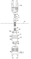
- the cable assembly 4 includes a signal-carrying cable 8 and a protector 12, with at least a portion of the signal-carrying cable 8 being disposed within an interior region of the protector 12.
- the signal-carrying cable 8 includes a cable 14 connected with a plug 16A at one end and connected with another plug 16B at another end.
- the signal-carrying cable 8 may be used to transmit fiber optic signals, electrical signals, or other signals without departing from the present concept.
- the plug 16A is structured to be connected with an electronic component of an electrical assembly.
- the plug 16A is structured to be connected with an electronic component that is situated within a quantity of potting compound that is schematically depicted as lying generally below a line indicated at the numeral 18 in Fig. 1 .
- the plug 16B is structured to be connected with another electronic component that may or may not be disposed within the potting compound.
- the protector 12 can be generally stated as comprising an elongated covering apparatus 20 and a clip 22.
- the covering apparatus 20 comprises a resilient portion 24 and a tubular element 28 that are connected together.
- the resilient portion 24 is formed from a resilient material such as a synthetic rubber, which in the exemplary embodiment is EPDM, or may be formed of another such material that is resilient in nature.
- the expression "resilient” and variations thereof shall refer generally to the property of returning to an original form or position after being bent, compressed, or stretched.
- the resilient portion 24 can be said to comprise a number of corrugations 32 disposed between a protrusion 36 and a connector 40.
- a number of'' and variations thereof shall refer generally to any non-zero quantity, include a quantity of one.
- the corrugations 32 enable the resilient portion 24 to be movable between a free state, such as is indicated generally in Fig. 3 , and a collapsed state, such as is indicated generally in Fig. 1 .
- the connector 40 includes a receptacle 44 within which is received an end of the tubular element 28.
- the tubular element 28 is an elongated hollow tube formed from a rigid but flexible plastic compound and which has the cable 14 disposed therein.
- the protrusion 36 is formed to have a passage 48 that extends therethrough and through which the cable 14 passes.
- the exemplary cable 14 is a dual-strand fiber optic cable in the exemplary embodiment presented herein, and the passage 48 thus is shaped as is indicated generally in Figs. 2 and 3 to receive the cable 14 therethrough.
- the improved cable assembly 4 is assembled by receiving an end of the tubular element 28 in the receptacle 44 and attaching a clamp 52B about an exterior surface of the connector 42 to securely connect together the connector 40 and the tubular element 28.
- a length of the cable 14 is then received through the interior of the tubular element 28, through the interior of the corrugations 32, and through the passage 48.
- Another clamp 52A is attached to an exterior surface of the protrusion 36 to securely connect together the protrusion 36 and the cable 14.
- the plugs 16A and 16B are then connected to the ends of the cable 14.
- the tubular element 28 is translated with respect to the cable 14 to move the corrugations 32 of the resilient portion 24 to their collapsed state.
- the clip 22 is then received on an end of the tubular element 28 and extends between the tubular element 28 and the cable 14.
- the clip 22, when installed as is indicated generally in Fig. 1 retains the resilient portion 24 in its collapsed state and also provides a fluid-resistant seal between the cable 14 and the end of the tubular element 28 where the clip 22 is situated.
- the uncured potting compound may then be poured into the electrical apparatus that includes the electronic component and in conjunction with which the cable assembly 4 is employed. The potting compound is then permitted or caused to cure, after which the clip 22 may be removed, if desired.
- he resilient portion 24 may be moved to the collapsed state and the clip 22 installed either prior to the connection of one or both of the plugs 16A and 16B with their corresponding electronic components or can be performed after such connection has occurred without departing from the present concept.
- Other such operations mentioned herein can be performed other than in the order expressly set forth herein without departing from the present concept.
- the clamps 52A and 52B advantageously resist the intrusion of uncured potting compound into the interior of the covering apparatus 20.
- the clip 22 likewise advantageously resists the entry of uncured potting compound into the covering apparatus 20.
- the potting compound in its cured state retains the resilient portion 24 substantially in its collapsed state which can provide a residual compressive force on the plug 16A in a direction generally toward the electronic component to which it is connected, which advantageously helps to retain the integrity of the connection. It is noted, however, that such residual compressive force is not necessarily required to enable the concept to work successfully.
- the resilient portion 24 in its collapsed state will provide a residual compressive force on the plug 16A to maintain the integrity of its connection with its associated electronic component.
- the resilient portion could enclose, in whole or in part, the electronic component to which the plug 16A is connected.
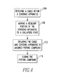
- FIG. 4 An improved method of disposing the cable assembly 4 and its signal-carrying cable 8 in a quantity of potting compound is depicted generally in Fig. 4 .
- the signal-carrying cable 8 is received in the covering apparatus 20, as is indicated generally at 104.
- the resilient portion 24 is then moved to its collapsed state, as is indicated generally at 108.
- the signal-carrying cable 8 and the covering apparatus 20 are then situated in the uncured potting compound, as at 112.
- the potting compound is then permitted to cure, as at 116.
- the specific order of the operations can be various without departing from the concept.
Landscapes
- Physics & Mathematics (AREA)
- General Physics & Mathematics (AREA)
- Optics & Photonics (AREA)
- Engineering & Computer Science (AREA)
- Architecture (AREA)
- Civil Engineering (AREA)
- Structural Engineering (AREA)
- Connector Housings Or Holding Contact Members (AREA)
- Details Of Connecting Devices For Male And Female Coupling (AREA)
Abstract
Description
- The disclosed and claimed concept relates generally to cables and, more particularly, to a cable assembly having a protector that protects the cable during use with a potting compound.
- Numerous types of potting compounds are generally known for use in conjunction with electrical and electronic equipment. A potting compound typically is a silicone or polyurethane substance that is initially in a liquid state and which cures into a semi-solid state. An electrical assembly that has been fully mechanically assembled may typically be filled with such a potting compound in order to enable the electrical assembly to resist shock and vibration and to exclude moisture and corrosive agents. The use of such potting compounds has not, however, been without limitation.
- One shortcoming with the use of potting compounds relates to the physical characteristics of the potting compound. For instance, some potting compounds can undergo thermal expansion when heated during normal use. In applications where large amounts of potting material, such as several cubic feet of potting material, are employed to fill a large electrical assembly, the amount of thermal expansion can be significant. Moreover, cured potting compound is not necessarily rigid and may be prone to vibration and jiggling in certain circumstances. Such vibration and jiggling can be significant in applications where large amounts of potting compound are used to fill an electrical assembly.
- The effects from such thermal expansion, vibration, and jiggling can loosen or break certain connections within the potted electrical assembly. By way of example, fiber optic connections are particularly prone to failure in large electronic assemblies that use large amounts of potting compound. It thus would be desirable to overcome these and other shortcomings associated with the use of large quantities of potting compound in electronic assemblies.
- Accordingly, an improved cable assembly and associated method of disposing the cable assembly in a quantity of potting compound overcome these and other shortcomings known in the art. An improved cable assembly includes at least a first elongated signal-carrying cable and a protector that comprises an elongated covering apparatus that is connected with the signal-carrying cable. The covering apparatus comprises a resilient portion having a number of corrugations and is movable between a free state and a collapsed state. The signal-carrying cable is received within the covering apparatus, and the resilient portion is moved from its free state to its collapsed state. A clip may be provided between the signal-carrying cable and the covering apparatus to retain the resilient portion in its compressed state. The signal-carrying cable and the covering apparatus are received at least partially in an uncured quantity of potting compound, and the compound is then permitted to cure.
- Accordingly, an aspect of the disclosed and claimed concept is to cause the resilient portion to be in a collapsed, i.e., compressed state after the quantity of potting compound has cured in order to apply a residual compression force on an electrical plug of a signal-carrying cable that is connected with an electronic component of an electrical assembly to maintain the connection between the plug and the electronic component.
- Another aspect of the disclosed and claimed concept is to resist the thermal expansion and vibration aspects that exist in association with the use of potting compounds.
- Accordingly, an aspect of the disclosed and claimed concept is to provide an improved cable assembly that is structured to be situated at least partially within a quantity of potting compound. The general nature of the cable assembly can be generally stated as including at least a first elongated signal-carrying cable, and a protector comprising an elongated covering apparatus that is connected with the at least first signal-carrying cable. The covering apparatus can be generally stated as including a resilient portion having a number of corrugations, with at least a portion of the at least first signal-carrying cable being disposed within the covering apparatus.
- Another aspect of the disclosed and claimed concept is to provide an improved protector that is structured to receive therein at least a portion of at least a first elongated signal-carrying cable and to be situated at least partially within a quantity of potting compound. The general nature of the protector can be stated as including an elongated covering apparatus that includes a resilient portion having a number of corrugations, with the covering apparatus being structured to be connected with the at least first signal-carrying cable.
- Another aspect of the disclosed and claimed concept is to provide an improved method of disposing at least a first elongated signal-carrying cable within a quantity of potting compound. The general nature of the method can be stated as including receiving at least a portion of the at least first signal-carrying cable within a protector that includes an elongated covering apparatus to connect together the covering apparatus and the at least first signal-carrying cable. The covering apparatus can be generally stated as including a resilient portion having a number of corrugations. The method can be stated as further including moving the resilient portion from a free state to a collapsed state, situating at least a portion of the at least first signal-carrying cable and at least a portion of the covering apparatus in an uncured quantity of potting compound, and curing the uncured quantity of potting compound.
- A further understanding of the disclosed and claimed concept can be gained from the following Description of the Preferred Embodiment when read in conjunction with the accompanying drawings in which:
-
Fig. 1 is a front elevational view of an improved cable assembly in accordance with the disclosed and claimed concept; -
Fig. 2 is an end view of a resilient portion of the cable assembly; -
Fig. 3 is a sectional view as taken along line 3-3 ofFig. 2 ; and -
Fig. 4 is a flowchart depicting certain aspects of an improved method in accordance with the disclosed and claimed concept. - Similar numerals refer to similar parts throughout the specification.
- An improved cable assembly 4 in accordance with the disclosed and claimed concept is depicted generally in
Fig. 1 . The cable assembly 4 includes a signal-carrying cable 8 and aprotector 12, with at least a portion of the signal-carrying cable 8 being disposed within an interior region of theprotector 12. The signal-carrying cable 8 includes a cable 14 connected with aplug 16A at one end and connected with anotherplug 16B at another end. The signal-carrying cable 8 may be used to transmit fiber optic signals, electrical signals, or other signals without departing from the present concept. Theplug 16A is structured to be connected with an electronic component of an electrical assembly. More particularly, theplug 16A is structured to be connected with an electronic component that is situated within a quantity of potting compound that is schematically depicted as lying generally below a line indicated at thenumeral 18 inFig. 1 . Theplug 16B is structured to be connected with another electronic component that may or may not be disposed within the potting compound. - The
protector 12 can be generally stated as comprising an elongated coveringapparatus 20 and aclip 22. The coveringapparatus 20 comprises aresilient portion 24 and atubular element 28 that are connected together. Theresilient portion 24 is formed from a resilient material such as a synthetic rubber, which in the exemplary embodiment is EPDM, or may be formed of another such material that is resilient in nature. As employed herein, the expression "resilient" and variations thereof shall refer generally to the property of returning to an original form or position after being bent, compressed, or stretched. - The
resilient portion 24 can be said to comprise a number ofcorrugations 32 disposed between aprotrusion 36 and aconnector 40. As employed herein, the expression "a number of'' and variations thereof shall refer generally to any non-zero quantity, include a quantity of one. Thecorrugations 32 enable theresilient portion 24 to be movable between a free state, such as is indicated generally inFig. 3 , and a collapsed state, such as is indicated generally inFig. 1 . - The
connector 40 includes areceptacle 44 within which is received an end of thetubular element 28. Thetubular element 28 is an elongated hollow tube formed from a rigid but flexible plastic compound and which has the cable 14 disposed therein. Theprotrusion 36 is formed to have apassage 48 that extends therethrough and through which the cable 14 passes. The exemplary cable 14 is a dual-strand fiber optic cable in the exemplary embodiment presented herein, and thepassage 48 thus is shaped as is indicated generally inFigs. 2 and 3 to receive the cable 14 therethrough. - Most typically, the improved cable assembly 4 is assembled by receiving an end of the
tubular element 28 in thereceptacle 44 and attaching aclamp 52B about an exterior surface of the connector 42 to securely connect together theconnector 40 and thetubular element 28. A length of the cable 14 is then received through the interior of thetubular element 28, through the interior of thecorrugations 32, and through thepassage 48. Anotherclamp 52A is attached to an exterior surface of theprotrusion 36 to securely connect together theprotrusion 36 and the cable 14. Theplugs - It is noted that when the
clamps resilient portion 24, the cable 14 becomes effectively affixed to theprotrusion 36 through thepassage 48 to form a fluid-resistant connection between the cable 14 and thepassage 48. Similarly, when theclamp 52B is received on the exterior surface of theconnector 40, a fluid-resistant connection is formed between thetubular element 28 and thereceptacle 44. It is noted, however, that the cable 14 is still slidable through thetubular element 28 in the vicinity of theconnector 40 despite the existence of theclamp 52B and the fluid-resistant connection that it causes to be formed between thetubular element 28 and thereceptacle 44. - In use, and typically after the cable assembly 4 has been constructed in the aforementioned fashion, the
tubular element 28 is translated with respect to the cable 14 to move thecorrugations 32 of theresilient portion 24 to their collapsed state. Theclip 22 is then received on an end of thetubular element 28 and extends between thetubular element 28 and the cable 14. Theclip 22, when installed as is indicated generally inFig. 1 , retains theresilient portion 24 in its collapsed state and also provides a fluid-resistant seal between the cable 14 and the end of thetubular element 28 where theclip 22 is situated. - Once the
plug 16A is connected with an electronic component that will be encased within the potting compound and theopposite plug 16B is connected with another electronic component that may or may not be encased within the potting compound, the uncured potting compound may then be poured into the electrical apparatus that includes the electronic component and in conjunction with which the cable assembly 4 is employed. The potting compound is then permitted or caused to cure, after which theclip 22 may be removed, if desired. - It is noted that he
resilient portion 24 may be moved to the collapsed state and theclip 22 installed either prior to the connection of one or both of theplugs - The
clamps covering apparatus 20. Theclip 22 likewise advantageously resists the entry of uncured potting compound into the coveringapparatus 20. The potting compound in its cured state retains theresilient portion 24 substantially in its collapsed state which can provide a residual compressive force on theplug 16A in a direction generally toward the electronic component to which it is connected, which advantageously helps to retain the integrity of the connection. It is noted, however, that such residual compressive force is not necessarily required to enable the concept to work successfully. Even in the event of thermal expansion, vibration, and jiggling of the potting compound, individually or in combination, theresilient portion 24 in its collapsed state will provide a residual compressive force on theplug 16A to maintain the integrity of its connection with its associated electronic component. In other embodiments, the resilient portion could enclose, in whole or in part, the electronic component to which theplug 16A is connected. - An improved method of disposing the cable assembly 4 and its signal-carrying cable 8 in a quantity of potting compound is depicted generally in
Fig. 4 . The signal-carrying cable 8 is received in thecovering apparatus 20, as is indicated generally at 104. Theresilient portion 24 is then moved to its collapsed state, as is indicated generally at 108. The signal-carrying cable 8 and thecovering apparatus 20 are then situated in the uncured potting compound, as at 112. The potting compound is then permitted to cure, as at 116. As mentioned elsewhere herein, the specific order of the operations can be various without departing from the concept. - While specific embodiments of the invention have been described in detail, it will be appreciated by those skilled in the art that various modifications and alternatives to those details could be developed in light of the overall teachings of the disclosure. Accordingly, the particular arrangements disclosed are meant to be illustrative only and not limiting as to the scope of invention which is to be given the full breadth of the claims appended and any and all equivalents thereof.
Claims (13)
- A cable assembly (4) structured to be situated at least partially within a quantity of potting compound, the cable assembly comprising:at least a first elongated signal-carrying cable (8); anda protector (12) comprising an elongated covering apparatus (20) that is connected with the at least first signal-carrying cable, the covering apparatus comprising a resilient portion (24) having a number of corrugations (32), at least a portion of the at least first signal-carrying cable being disposed within the covering apparatus.
- The cable assembly of Claim 1 wherein the covering apparatus further comprises an elongated tubular element (28) that is connected with the resilient portion, at least a portion of the at least first signal-carrying cable being disposed within the tubular element.
- The cable assembly of Claim 2 wherein the resilient portion comprises a connector (40) that is connected with the tubular element.
- The cable assembly of Claim 3 wherein the connector comprises a receptacle (44) within which is received an end of the tubular element.
- The cable assembly of Claim 2 wherein at least a first corrugation from among the number of corrugations is disposed between the connector and the at least first signal-carrying cable.
- The cable assembly of Claim 2 wherein the resilient portion is movable between a free state and a collapsed state, and wherein the protector further comprises a clip (22) that extends between the tubular element and the at least first signal-carrying cable, the clip retaining the resilient portion in the collapsed state.
- The cable assembly of Claim 1 wherein the resilient portion is connected with the at least first signal-carrying cable.
- A protector (12) structured to receive therein at least a portion of at least a first elongated signal-carrying cable (8) and to be situated at least partially within a quantity of potting compound, the protector comprising an elongated covering apparatus (20) that comprises a resilient portion (24) having a number of corrugations (32), the covering apparatus being structured to be connected with the at least first signal-carrying cable.
- The protector of Claim 8 wherein the covering apparatus further comprises an elongated tubular element (28) that is connected with the resilient portion.
- The protector of Claim 9 wherein the resilient portion comprises a connector (40) that is connected with the tubular element.
- The protector of Claim 10 wherein the connector comprises a receptacle (44) within which is received an end of the tubular element.
- A method of disposing at least a first elongated signal-carrying cable (8) within a quantity of potting compound, the method comprising:receiving (104) at least a portion of the at least first signal-carrying cable within a protector (12) that comprises an elongated covering apparatus (20) to connect together the covering apparatus and the at least first signal-carrying cable, the covering apparatus comprising a resilient portion (24) having a number of corrugations (32);moving (108) the resilient portion from a free state to a collapsed state;situating (112) at least a portion of the at least first signal-carrying cable and at least a portion of the covering apparatus in an uncured quantity of potting compound; andcuring (116) the uncured quantity of potting compound.
- The method of Claim 12, further comprising applying a clip (22) between the at least first signal-carrying cable and the covering apparatus to retain the resilient portion in the compressed state prior to the curing.
Applications Claiming Priority (1)
| Application Number | Priority Date | Filing Date | Title |
|---|---|---|---|
| US12/795,275 US8395044B2 (en) | 2010-06-07 | 2010-06-07 | Cable assembly with protector, and accompanying method |
Publications (1)
| Publication Number | Publication Date |
|---|---|
| EP2392956A1 true EP2392956A1 (en) | 2011-12-07 |
Family
ID=44544238
Family Applications (1)
| Application Number | Title | Priority Date | Filing Date |
|---|---|---|---|
| EP11004638A Withdrawn EP2392956A1 (en) | 2010-06-07 | 2011-06-07 | Cable assembly with protector, and accompanying method |
Country Status (5)
| Country | Link |
|---|---|
| US (1) | US8395044B2 (en) |
| EP (1) | EP2392956A1 (en) |
| AU (1) | AU2011202870A1 (en) |
| BR (1) | BRPI1102979A2 (en) |
| CA (1) | CA2742280A1 (en) |
Cited By (1)
| Publication number | Priority date | Publication date | Assignee | Title |
|---|---|---|---|---|
| WO2013145751A3 (en) * | 2012-03-30 | 2013-11-14 | Yazaki Corporation | Harness exterior protector |
Families Citing this family (4)
| Publication number | Priority date | Publication date | Assignee | Title |
|---|---|---|---|---|
| JP7491062B2 (en) * | 2020-06-03 | 2024-05-28 | 住友電装株式会社 | Wiring materials |
| CN112271503A (en) * | 2020-10-22 | 2021-01-26 | 深圳华添达信息技术有限公司 | Cable for converting external SAS interface into internal interface |
| CN113809704B (en) * | 2021-09-17 | 2025-07-29 | 沈阳兴华航空电器有限责任公司 | Sealing element for cabin penetrating engine cable |
| CN118676663B (en) * | 2024-08-20 | 2024-11-12 | 合肥综合性国家科学中心能源研究院(安徽省能源实验室) | A high voltage cable integrated vacuum feed-in device |
Citations (5)
| Publication number | Priority date | Publication date | Assignee | Title |
|---|---|---|---|---|
| GB482061A (en) * | 1937-01-01 | 1938-03-23 | Pirelli General Cable Works | Improvements in or relating to sleeves for electric cable joints |
| US5192948A (en) * | 1991-11-04 | 1993-03-09 | Mobil Oil Corporation | Geophone borehole cable |
| US5199100A (en) * | 1992-02-21 | 1993-03-30 | Litton Systems, Inc. | Wet end termination for towed cable |
| US5793916A (en) * | 1996-12-03 | 1998-08-11 | Jds Fitel Inc. | Hermetically sealed connection assembly for two or more optical fibers |
| US20050037656A1 (en) * | 2003-08-26 | 2005-02-17 | Cairns James L. | Dry mate connector |
Family Cites Families (3)
| Publication number | Priority date | Publication date | Assignee | Title |
|---|---|---|---|---|
| US3621447A (en) * | 1969-12-22 | 1971-11-16 | Us Navy | Deep submergence electrical assembly |
| US4469392A (en) * | 1982-03-19 | 1984-09-04 | Mobil Oil Corporation | Ocean bottom seismic cable connector |
| FR2883107B1 (en) * | 2005-03-09 | 2007-05-11 | Cf Gomma Spa | CONNECTION-FIXED CONNECTION DEVICE FOR PASSING AND PROTECTING ELECTRIC CABLES, OR THE LIKE AND METHOD OF MANUFACTURING THE SAME |
-
2010
- 2010-06-07 US US12/795,275 patent/US8395044B2/en not_active Expired - Fee Related
-
2011
- 2011-06-07 BR BRPI1102979-0A patent/BRPI1102979A2/en not_active Application Discontinuation
- 2011-06-07 EP EP11004638A patent/EP2392956A1/en not_active Withdrawn
- 2011-06-07 CA CA2742280A patent/CA2742280A1/en not_active Abandoned
- 2011-06-15 AU AU2011202870A patent/AU2011202870A1/en not_active Abandoned
Patent Citations (5)
| Publication number | Priority date | Publication date | Assignee | Title |
|---|---|---|---|---|
| GB482061A (en) * | 1937-01-01 | 1938-03-23 | Pirelli General Cable Works | Improvements in or relating to sleeves for electric cable joints |
| US5192948A (en) * | 1991-11-04 | 1993-03-09 | Mobil Oil Corporation | Geophone borehole cable |
| US5199100A (en) * | 1992-02-21 | 1993-03-30 | Litton Systems, Inc. | Wet end termination for towed cable |
| US5793916A (en) * | 1996-12-03 | 1998-08-11 | Jds Fitel Inc. | Hermetically sealed connection assembly for two or more optical fibers |
| US20050037656A1 (en) * | 2003-08-26 | 2005-02-17 | Cairns James L. | Dry mate connector |
Cited By (1)
| Publication number | Priority date | Publication date | Assignee | Title |
|---|---|---|---|---|
| WO2013145751A3 (en) * | 2012-03-30 | 2013-11-14 | Yazaki Corporation | Harness exterior protector |
Also Published As
| Publication number | Publication date |
|---|---|
| AU2011202870A1 (en) | 2011-12-22 |
| BRPI1102979A2 (en) | 2014-01-07 |
| US8395044B2 (en) | 2013-03-12 |
| CA2742280A1 (en) | 2011-12-07 |
| US20110297440A1 (en) | 2011-12-08 |
Similar Documents
| Publication | Publication Date | Title |
|---|---|---|
| US8395044B2 (en) | Cable assembly with protector, and accompanying method | |
| TW200937787A (en) | Cold shrink article and method of using cold shrink article | |
| CN110233391B (en) | Sealing cover sleeves and covers and interconnecting joints protected thereby | |
| CN102668287B (en) | Wraparound cable gland assembly and methods of making and using same | |
| US9063286B2 (en) | Flex tactical cable splice | |
| JP2016524663A (en) | Individual sealed configuration for cable mooring equipment | |
| KR20100061527A (en) | Article and method for sealing fluid-containing cables | |
| EP3807685A1 (en) | Methods, kits, and systems incorporating a self-amalgamating tape for clamping fiber optic cable | |
| JPH03143217A (en) | Enclosure of connection part | |
| US6979133B2 (en) | Epoxy bonded fiber optic connector and method of constructing same | |
| US20150170790A1 (en) | Systems and methods for resin infused harness construction | |
| US10283878B2 (en) | Neutral conductor connection protection devices and cover assembly kits, electrical connections and methods including same | |
| US11728071B2 (en) | Cable assembly with bundling arrangement | |
| CN117810898A (en) | Sealing structure, cable and cable equipment | |
| JP4288122B2 (en) | Terminal fixing method and terminal fixing body of high-strength fiber composite cable | |
| US8883061B2 (en) | Cover assemblies for electrical cables and methods and kits including same | |
| CN202772331U (en) | Small-diameter cable bunch | |
| AU578702B2 (en) | Encapsulation system for cable splice | |
| KR101188059B1 (en) | Cable jointing method using spiral core | |
| EP3683609A1 (en) | Sheathed optical ribbon cable assembly | |
| PL188021B1 (en) | Clamping holder in particular for cables and method of mounting such holder | |
| CN107864549A (en) | For crossing the field apparatus of process automation | |
| CN102831985A (en) | Cable assembly with protector and relevant method | |
| JP4731258B2 (en) | Fiber optic bundle | |
| CN220122529U (en) | Automobile wire harness protective sleeve |
Legal Events
| Date | Code | Title | Description |
|---|---|---|---|
| AK | Designated contracting states |
Kind code of ref document: A1 Designated state(s): AL AT BE BG CH CY CZ DE DK EE ES FI FR GB GR HR HU IE IS IT LI LT LU LV MC MK MT NL NO PL PT RO RS SE SI SK SM TR |
|
| AX | Request for extension of the european patent |
Extension state: BA ME |
|
| PUAI | Public reference made under article 153(3) epc to a published international application that has entered the european phase |
Free format text: ORIGINAL CODE: 0009012 |
|
| RIN1 | Information on inventor provided before grant (corrected) |
Inventor name: FARR, THOMAS A. Inventor name: RAVENELL, RICHARD B. Inventor name: MULLIGAN, PAUL Inventor name: GIBBS, IRVING ALBERT |
|
| 17P | Request for examination filed |
Effective date: 20120529 |
|
| STAA | Information on the status of an ep patent application or granted ep patent |
Free format text: STATUS: THE APPLICATION IS DEEMED TO BE WITHDRAWN |
|
| 18D | Application deemed to be withdrawn |
Effective date: 20160105 |