EP2392816A1 - Stress Relief in Pressurized Fluid Flow System - Google Patents
Stress Relief in Pressurized Fluid Flow System Download PDFInfo
- Publication number
- EP2392816A1 EP2392816A1 EP20100164871 EP10164871A EP2392816A1 EP 2392816 A1 EP2392816 A1 EP 2392816A1 EP 20100164871 EP20100164871 EP 20100164871 EP 10164871 A EP10164871 A EP 10164871A EP 2392816 A1 EP2392816 A1 EP 2392816A1
- Authority
- EP
- European Patent Office
- Prior art keywords
- face
- drilled
- stress
- loading
- intersection
- Prior art date
- Legal status (The legal status is an assumption and is not a legal conclusion. Google has not performed a legal analysis and makes no representation as to the accuracy of the status listed.)
- Granted
Links
Images





Classifications
-
- F—MECHANICAL ENGINEERING; LIGHTING; HEATING; WEAPONS; BLASTING
- F02—COMBUSTION ENGINES; HOT-GAS OR COMBUSTION-PRODUCT ENGINE PLANTS
- F02M—SUPPLYING COMBUSTION ENGINES IN GENERAL WITH COMBUSTIBLE MIXTURES OR CONSTITUENTS THEREOF
- F02M61/00—Fuel-injectors not provided for in groups F02M39/00 - F02M57/00 or F02M67/00
- F02M61/16—Details not provided for in, or of interest apart from, the apparatus of groups F02M61/02 - F02M61/14
- F02M61/168—Assembling; Disassembling; Manufacturing; Adjusting
-
- C—CHEMISTRY; METALLURGY
- C21—METALLURGY OF IRON
- C21D—MODIFYING THE PHYSICAL STRUCTURE OF FERROUS METALS; GENERAL DEVICES FOR HEAT TREATMENT OF FERROUS OR NON-FERROUS METALS OR ALLOYS; MAKING METAL MALLEABLE, e.g. BY DECARBURISATION OR TEMPERING
- C21D7/00—Modifying the physical properties of iron or steel by deformation
- C21D7/02—Modifying the physical properties of iron or steel by deformation by cold working
- C21D7/10—Modifying the physical properties of iron or steel by deformation by cold working of the whole cross-section, e.g. of concrete reinforcing bars
-
- C—CHEMISTRY; METALLURGY
- C21—METALLURGY OF IRON
- C21D—MODIFYING THE PHYSICAL STRUCTURE OF FERROUS METALS; GENERAL DEVICES FOR HEAT TREATMENT OF FERROUS OR NON-FERROUS METALS OR ALLOYS; MAKING METAL MALLEABLE, e.g. BY DECARBURISATION OR TEMPERING
- C21D9/00—Heat treatment, e.g. annealing, hardening, quenching or tempering, adapted for particular articles; Furnaces therefor
- C21D9/0068—Heat treatment, e.g. annealing, hardening, quenching or tempering, adapted for particular articles; Furnaces therefor for particular articles not mentioned below
-
- F—MECHANICAL ENGINEERING; LIGHTING; HEATING; WEAPONS; BLASTING
- F02—COMBUSTION ENGINES; HOT-GAS OR COMBUSTION-PRODUCT ENGINE PLANTS
- F02M—SUPPLYING COMBUSTION ENGINES IN GENERAL WITH COMBUSTIBLE MIXTURES OR CONSTITUENTS THEREOF
- F02M2200/00—Details of fuel-injection apparatus, not otherwise provided for
- F02M2200/80—Fuel injection apparatus manufacture, repair or assembly
- F02M2200/8053—Fuel injection apparatus manufacture, repair or assembly involving mechanical deformation of the apparatus or parts thereof
-
- Y—GENERAL TAGGING OF NEW TECHNOLOGICAL DEVELOPMENTS; GENERAL TAGGING OF CROSS-SECTIONAL TECHNOLOGIES SPANNING OVER SEVERAL SECTIONS OF THE IPC; TECHNICAL SUBJECTS COVERED BY FORMER USPC CROSS-REFERENCE ART COLLECTIONS [XRACs] AND DIGESTS
- Y10—TECHNICAL SUBJECTS COVERED BY FORMER USPC
- Y10T—TECHNICAL SUBJECTS COVERED BY FORMER US CLASSIFICATION
- Y10T137/00—Fluid handling
- Y10T137/8593—Systems
-
- Y—GENERAL TAGGING OF NEW TECHNOLOGICAL DEVELOPMENTS; GENERAL TAGGING OF CROSS-SECTIONAL TECHNOLOGIES SPANNING OVER SEVERAL SECTIONS OF THE IPC; TECHNICAL SUBJECTS COVERED BY FORMER USPC CROSS-REFERENCE ART COLLECTIONS [XRACs] AND DIGESTS
- Y10—TECHNICAL SUBJECTS COVERED BY FORMER USPC
- Y10T—TECHNICAL SUBJECTS COVERED BY FORMER US CLASSIFICATION
- Y10T408/00—Cutting by use of rotating axially moving tool
- Y10T408/03—Processes
-
- Y—GENERAL TAGGING OF NEW TECHNOLOGICAL DEVELOPMENTS; GENERAL TAGGING OF CROSS-SECTIONAL TECHNOLOGIES SPANNING OVER SEVERAL SECTIONS OF THE IPC; TECHNICAL SUBJECTS COVERED BY FORMER USPC CROSS-REFERENCE ART COLLECTIONS [XRACs] AND DIGESTS
- Y10—TECHNICAL SUBJECTS COVERED BY FORMER USPC
- Y10T—TECHNICAL SUBJECTS COVERED BY FORMER US CLASSIFICATION
- Y10T408/00—Cutting by use of rotating axially moving tool
- Y10T408/21—Cutting by use of rotating axially moving tool with signal, indicator, illuminator or optical means
Definitions
- the invention relates to stress relief in a pressurized fluid flow system, in particular a system in which fluid flows at high pressure through a component bore.
- the invention is particularly applicable where a component or element with a primary bore requires a secondary bore which has an intersection with the primary bore.
- High pressure fluid flow systems need to be designed to resist significant operational stresses.
- An example of such a fluid flow system is a fuel injector for use in the delivery of fuel to a combustion space of an internal combustion engine.
- fuel injectors For heavy-duty applications, such as fuel injection for diesel engines for trucks, fuel injectors must be capable of delivering fuel in small quantities at very high pressures (of the order of 300MPa).
- Tensile stress is a significant cause of failure in such systems - cracks will be propagated by tensile stress but not by compressive stress.
- the intersection between two fluid bores has a significant failure risk associated with it in such a system, as it generally acts as a concentrator for tensile stress.
- material grade In order to reduce the cost of products, it is also desirable to reduce material grade. This would usually reduce material strength, which can increase the failure risk at such intersections.
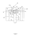
- FIG. 1 shows an example of such a component stack used in such a fuel injector design.
- This fuel injector discussed in full in European Patent Application No. 09168746.7 , is discussed here to illustrate where such intersections may be required in such a design.
- Figure 1 shows a schematic view of a part of a fuel injector for use in delivering fuel to a combustion space of an internal combustion engine.
- the fuel injector comprises a valve needle 20 (shown in part) and a three way needle control valve (NCV) 10.
- the injector includes a guide body 12.
- the NCV 10 is housed within a valve housing 14 and a shim plate 16, which spaces apart the guide body 12 and the valve housing 14.
- the valve needle 20 is operable by means of the NCV 10 to control fuel flow into an associated combustion space (not shown) through nozzle outlet openings.
- the lower part of the valve needle (not shown) terminates in a valve tip which is engageable with a valve needle seat so as to control fuel delivery through the outlet openings into the combustion space.
- An upper end of the valve needle 20 is located within a control chamber 18 defined within the injector body. This upper end slides within a guide bore 22 in the guide body 12 and acts as a piston.
- the control chamber 18 has two openings. One, at the top of the control chamber 18, leads to a first axial drilling 42 in the shim plate 16.
- the other at the side of the control chamber 18, opens into a flow passage 52 in the guide body 12 that itself leads to a second axial drilling 44 in the shim plate 16. Both these axial drillings 42, 44 connect, through a cross slot 46, to a shim plate chamber 36 used for the NCV 10.
- the NCV 10 controls the pressure of fuel within the control chamber 18.
- the NCV includes a valve pin with an upper guide portion 32a and a lower valve head portion 32b.
- the guide portion 32a slides within a guide bore 34 defined in a NCV housing 14.
- the valve head 32b slides within the chamber 36 between two valve seats 48, 50.
- High pressure fuel reaches the NCV 10 through a supply passage 30 extending through the guide body 12 and the shim plate 16, the supply passage 30 communicating with the NCV through a passage entering the guide bore 34 from the side.
- Fuel can leave the NCV through the cross slot 46 as discussed above or through a drain passage 38 communicating with a low pressure drain.
- the NCV 10 controls the pressure in the control chamber 18 and hence movement of the valve needle 20.
- fuel flows through the NCV 10 through the cross slot 46 and into the control chamber 18 to pressurise it, and in another position fuel cannot flow into the control chamber 18 but instead drains from it through to the cross slot 46 and hence to the drain 40.
- European Patent Application No. 09168746.7 The specific details of this arrangement are described in more detail in European Patent Application No. 09168746.7 .
- Figure 1 illustrates the use of cross drillings in high-pressure injector designs.
- flow passage 52 is a cross drilling in the guide body 12 into the control chamber 18; and fuel supply 30 flows into guide bore 34 through a cross drilling in the valve housing 14. Both these cross drillings experience cycling between low and very high pressure, and are thus exposed to very high tensile stresses. This creates a significant risk of early component failure through crack propagation.
- a system for pressurised fluid flow comprising a drilled element and a first loading element, wherein the drilled element has a primary bore and a secondary bore with an intersection therebetween, wherein the primary bore extends from a first face of the drilled element, and wherein the first loading element loads the first face of the drilled element; and wherein a stress relief layer is provided between the first face of the drilled element and a corresponding face of the first loading element, whereby loading force is provided to the drilled element from the first loading element through the stress relief layer; whereby the stress relief layer extends underneath at least the intersection between the primary bore and the secondary bore, but does not extend over at least a part of the first face of the drilled element; and whereby the intersection is sufficiently close to the first face of the drilled element such that, in use, the loading force provides compressive stress in the drilled element at the intersection.
- This arrangement achieves reduction in tensile stress at the failure point without the need for pre-processing steps (such as shot peening and autofrettage) which are expensive and which may also cause robustness issues.
- the arrangement taught simply uses loading forces to move the intersection towards a compressive stress regime, which is well tolerated, from a tensile stress regime, which is likely to lead to failure.
- the stress relief layer is disposed around and adjacent to the primary bore.
- the stress relief layer is integrally formed on the first face of the drilled element.
- the stress relief layer may be substantially annular.
- a ratio of the outer diameter of the stress relief layer to the diameter of the primary bore may be between 2 and 7, particularly between 2.5 and 5, and most particularly between 3 and 4.
- the drilled component may be substantially cylindrical.
- a ratio of the outer diameter of the drilled element to the diameter of the primary bore may be greater than 5, preferably greater than 8.
- the loading force provides Poisson effect stress in the stress relief layer which further provides compressive stress in the drilled element at the intersection.
- the system further comprises a second loading element, wherein the primary bore extends to a second face of the drilled element, and wherein the second loading element loads the second face of the drilled element.
- This combination of loading forces - their application and location - provides a bending moment in the drilled element which provides compressive stress in the drilled element at the intersection.
- a ratio of the width of the drilled element to the height of the drilled element in such arrangements may be at least 2, preferably at least 4.
- a second stress relief layer may be provided between the second face of the drilled element and the second loading element, whereby the second stress relief layer is generally disposed further from the primary bore than the stress relief layer.
- the inner diameter of the second stress relief layer may be greater than the outer diameter of the stress relief layer.
- stress relief layer here is used to describe layers which serve to relieve stress from a part of the drilled component by the mechanisms described. These layers lie between two faces - a face of the drilled element and a face of the loading element - and only cover a part of the relevant faces, which means that the loading force will be transmitted through the stress relief layer. It will of course be appreciated by the person skilled in the art that these layers can in some sense be considered stress concentrators (in that they will lead directly to local compressive stresses), but the term “stress relief layer” is used here in the light of the functional role of these layers.
- the ratio between the distance from the centre of the secondary bore to a face of the stress relief layer adjacent to the first loading element to the diameter of the primary bore may be less than 2, preferably less than 1.
- the stress relief layer may extend further under the intersection than in another part of the first face. Oone or more load balancing regions may then be provided between the first face of the drilled element and the corresponding face of the first loading element.
- the secondary bore is substantially orthogonal to the primary bore. In others, the secondary bore forms an acute angle with the primary bore between the intersection and the stress relief layer.
- the primary bore is tapered such that when the drilled element is loaded between the first and second loading elements, the loading forces cause the walls of the primary bore to become substantially straight.
- the taper in at least part of the primary bore may be at least 0.1 %.
- the invention provides a drilled element for use in the system for pressurised fluid flow as described above.
- the invention provides a method of reducing tensile stress at an intersection between a primary bore and a secondary bore in a drilled element used within a system for pressurised fluid flow, the method comprising: loading the drilled element between a first loading element and a second loading element, wherein the first loading element loads a first face of the drilled element and the second loading element loads a second face of the drilled element; providing means to generate a compressive hoop stress where the first face of the drilled element is loaded by the first loading element, wherein the intersection is sufficiently close to the first face of the drilled element such that, in use, the compressive hoop stress counteracts tensile stress in the drilled element at the intersection.
- the system for pressurised fluid flow may be a fuel injector for use with an internal combustion engine.
- Figure 2 shows elements used in embodiments of the invention.
- Figure 2 provides a generalised representation of a component 100 used for high pressure fluid flow.
- This component 100 is shown here as being radially symmetric about a primary bore 110, though as will be described further below, such radial symmmetry need not be provided in all embodiments.
- the component 100 is in use compressed between other parts in a component stack - these other parts will define a fluid path in to and out of the primary bore 110, and the compression will prevent leakage at the boundary between the component 100 and these other parts, which act as loading elements on the component 100.
- the component 100 has a secondary bore 120 that intersects with the primary bore 110 at an intersection 130.
- a high pressure fluid flow regime particularly one which cycles rapidly and repeatedly between high and low pressures
- such an intersection 130 will generally be exposed to significant tensile stress unless steps are taken to alleviate this.
- a stress relief layer 140 here termed a "face relief”
- This face relief 140 is located around the primary bore 110 on one face (here, the lower face 150) of the component 100, and at least a part is disposed underneath the intersection 130.
- a greater part of the lower face 150 has no face relief region, as this only occupies a small proportion of the area of the lower face in the region of the primary bore 110.
- Figure 3A shows the effect of loading on a solid component capable of some degree of elastic deformation.
- the upper part of the component is not shown (it can be assumed that this will be loaded in such a way as to provide a balance of forces).
- Contact pressure from below, as shown, will result in compression in the vertical direction and consequently lateral expansion according to the Poisson Effect.
- the degree of expansion (or strain) is a function of the Poisson's ratio of the material and from the geometry of the component.
- the Poisson's ratio may be determined according to known methods (the Poisson's ration of a typical steel - as might be used in a fuel injector component - is approximately 0.3).
- Figure 3B shows the application of such loading to a component with a central bore, rather than to a solid component.
- the horizontal deformation resulting from the vertical compression promote expansion of the outer diameter of the loaded component but also contraction of the inner diameter of the central bore.
- Figure 3C shows the effect of restraining the radial displacement of the external diameter of the loaded component from above with a much larger component with a much greater outer diameter but a similar central bore - the loaded component shown in Figure 3C may be considered equivalent to the face relief 140 of Figure 2 , with the much larger component (not shown in Figure 3C ) being equivalent to the bulk part of the component 100.
- the effect of the much larger component is to fix the outer diameter of the loaded component in position. This means that the radial displacement resulting from the Poisson's ratio of the material may only act on the central bore of the loaded component (which is not pinned by the much larger component, as it also has a central bore). This provides a significant compressive hoop stress. A resulting hoop stress will also be present in the much larger component, though its value will fall away with increased distance from the loaded component.
- Figure 3D shows the significance of this arrangement for an intersection with a secondary bore. As discussed above, this is normally a region of increased tensile stress, particularly during pressurised flow. The compressive hoop stress resulting from the Poisson effect is however also present at the intersection point. In fact, if located in a region where this Poisson effect applies strongly the control drilling will act as a stress raiser for this compressive stress (much as it conventionally acts as a tensile stress raiser in a pressurised fluid flow regime).
- Figure 4A shows stress against time at the intersection point in a conventional arrangement (line 401) and where the Poisson effect regime of Figure 3D applies (line 402). Where there is no compressive stress provided by the Poisson effect (or by any other mechanism - an additional mechanism is discussed further below), cycling between high and low pressure leads to repeated very high net tensile stress at the intersection (as shown by line 401).
- Poisson effect compressive stress is provided as indicated above, this makes no change to the amplitude of the variations in stress between the high and low pressure regimes, but it does move the baseline strongly into the compressive regime, and hence the stress at peak pressure into the weakly tensile regime (as shown here by line 402 - with appropriate design choices the intersection could be kept in the compressive regime at all operating pressures).
- Figure 5 illustrates qualititatively the change in compressive stress seen at the intersection for a given loading force F and cross drilling height h (as shown in Figure 2 ) against annular width x of the face relief.
- Position 510 shows a low resultant compressive hoop stress - as can be seen, the small face relief creates a small region 511 of high compressive hoop stress in the main component, but this region 511 is so small that the intersection between bores lies outside it and the compressive hoop stress seen at the intersection is minimal.
- Position 520 shows - for this geometry - an optimal compressive hoop stress at the intersection.
- Figure 6 shows qualitatively the compressive stress curves for a given force F with varying annular width x, different curves being shown for different intersection heights h.
- the peak compressive stresses show track through a broadly optimum intersection height to face relief ratio h/x - curve 601 tracks this ratio through the minima of separate stress curves 610, 620 and 630 for different heights.
- Figures 7 to 9 indicate the effect on stress at the intersection of varying certain of the variables shown in Figure 2 determined by finite element analysis of the system.
- Figure 7 shows the effect of varying the outer diameter D' of the component for a fixed face relief size relative to the diameter d of the primary bore.
- the ratio D'/d is small, there is no useful compressive stress effect - this ratio needs to be at least 5 before the effect becomes useful. This is because if the ratio D'/d is small then the part simply does not have enough bulk to prevent outer diameter deformation as shown in Figure 3B , that deformation not leading to compressive stress. When the ratio reaches 8, then there is useful compressive stress provided at both the top and bottom of the lateral drilling (and hence also the intersection).
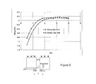
- Figure 8 shows the effect of varying drilling height h for fixed face relief size and component diameters - in this case, the ratio of face relief outer diameter D to primary bore diameter is chosen to be 3.
- the compressive stress effect begins to be apparent when the value of h/d is reduced to 2, and becomes more significant when this ratio is reduced further.
- a large compressive stress effect is present when h/d is 1 or lower.
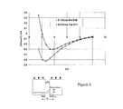
- Figure 9 shows the effect of varying the outer diameter D of the face relief with other component diameters and drilling height h fixed.
- too small a face relief provides a great compressive stress concentration but located too low in the component to affect the drilling, whereas too large a face relief provides insufficient compressive stress to relieve the tensile stress at the intersection effectively.
- a useful effect is found when D/d lies between 2 and 7, a stronger effect is found when D/d lies between 2.5 and 5, and a very strong effect when D/d lies between 3 and 4.
- Figures 10A to 10C indicate a modification to the arrangement shown in Figure 2 that illustrates a further aspect of embodiments of the invention.
- the component 100a is as shown in Figure 2 but it also has a further face relief 170 on an upper face 160 of the component, as is apparent from Figure 10A .
- the upper face relief 170 has a much larger inner and outer diameter than the lower face relief 140. For a relatively thin component 100a, this leads to another mechanism for providing compressive stress at the intersection 130.
- Figure 10B indicates the effect of loading the component 100a from above and from below.
- the action of the loading forces through the two face reliefs 140, 170 results in a bending moment in the component 100a.
- this bending moment leads to creation of compressive hoop stress in the bore region at the smaller lower face relief 140 and tensile hoop stress in the bore region at the upper face 160 of the component 100a. If the component 100a is relatively thick in relation to its outer diameter, this effect will be small, but if it is thin, it will be significant.
- Figure 10C which shows stresses in the region of the intersection 130, the intersection again acts as a stress concentrator and so a concentrator for the compressive hoop stress resulting from this bending moment.
- FIG 11 indicates the variation in stress at the intersection with the ration between component height H and component diameter D' for a given bore diameter d and intersection height h. It can be seen that compressive hoop stress is not present at a significant degree until D'/H is 2 or greater (H/D' is 0.5 or less), but that the effect has become much more significant when D'/H is 4 or greater (H/D' is 0.25 or less).
- the Poisson effect compressive stress shown in Figures 3A to 3D and the bending moment compressive stress shown in Figures 10A to 10C can be used together to build in compressive stress at the intersection 130 in the arrangement of Figure 2 .
- Either effect may be used on its own to provide a compressive effect at the intersection - while in embodiments shown here the bending moment effect is used primarily to augment the Poisson effect compressive stress, there are arrangements in which it may be valuable on its own.
- Figure 12 shows a further embodiment of a component design which uses a face relief to provide compressive hoop stress at an intersection.
- This component 100b is viewed from below, and it can be seen that the face relief 140a provided about the primary bore 110 is not axially symmetric.
- the face relief 140a is provided with a larger land 141 underneath the intersection 130 than in other parts of the face relief 140a.
- This radial asymmetry is chosen in order to concentrate compressive hoop stress further in the region of the intersection 130, rather than radially symmetrically around the primary bore 110 (noting that this radial symmetry will already be broken by the stress concentrating effect of the presence of the intersection 130).
- compensatory lands 142 and 143 are provided to balance the effect of the asymmetry of the face relief 140a.
- Figure 13 A further modification to the arrangement of Figure 2 is shown in Figure 13 .
- the secondary bore 120b is not orthogonal to the primary bore 110, but is instead at an angle to it. This may be used to balance the stresses at the intersection, as in this arrangement the lower part of the intersection 130 would normally be more stressed, but as it is closer to the face relief it will also be provided with a greater compressive hoop stress to compensate.
- the face relief is not required to provide a sealing force for fluid flow, more flexibility in design is available.
- the further face relief 170 may not be required to provide a sealing force, and may not need to be an annulus as is shown in Figure 10A .
- this face relief 170 may be provided as a plurality of pads disposed symmetrically around the primary bore 110.
- Figures 14A and 14B show a potential modification to the primary bore 110a in embodiments of a component using the approaches to stress relief provided above.
- Many such components will operate with a needle shaped piston 170 reciprocating within the primary bore 110a - possibly in such a way as to seal off flow from secondary bore 120 into the primary bore 110a.
- Use of the face relief 140 to generate a compressive hoop stress may lead to some change in shape of the bores. For example, the stresses at the intersection 130 will tend to distort the secondary bore 120 at the intersection 130 into a vertically elongated "rugby ball" shape.
- the use of compressive hoop stress may lead to a reduction in the diameter of the primary bore 110a in the region of the lower face 150 of the component compared to that at the upper face 160 of the component. It is however desirable for the needle shaped piston 170 to be a relatively tight fit within the bore to ensure efficient sealing without leakage.
- This can be accomplished by providing the primary bore 110a with a taper in its unloaded state (shown in Figure 14A ), such that loading, and compressive hoop stress in the region of the intersection 130, will return the primary bore 110a (as shown in Figure 14B ) to a substantially constant diameter in the operational range of the piston - an alternative approach is to taper the piston and not the bore.
- the approximate taper in diameter required may be approximately 10 ⁇ m over a length of 3 to 5mm.
Landscapes
- Engineering & Computer Science (AREA)
- Chemical & Material Sciences (AREA)
- Mechanical Engineering (AREA)
- Organic Chemistry (AREA)
- Materials Engineering (AREA)
- Metallurgy (AREA)
- Crystallography & Structural Chemistry (AREA)
- Physics & Mathematics (AREA)
- Thermal Sciences (AREA)
- Manufacturing & Machinery (AREA)
- Combustion & Propulsion (AREA)
- General Engineering & Computer Science (AREA)
- Fuel-Injection Apparatus (AREA)
Abstract
Description
- The invention relates to stress relief in a pressurized fluid flow system, in particular a system in which fluid flows at high pressure through a component bore. The invention is particularly applicable where a component or element with a primary bore requires a secondary bore which has an intersection with the primary bore.
- High pressure fluid flow systems need to be designed to resist significant operational stresses. An example of such a fluid flow system is a fuel injector for use in the delivery of fuel to a combustion space of an internal combustion engine. For heavy-duty applications, such as fuel injection for diesel engines for trucks, fuel injectors must be capable of delivering fuel in small quantities at very high pressures (of the order of 300MPa).
- Tensile stress is a significant cause of failure in such systems - cracks will be propagated by tensile stress but not by compressive stress. The intersection between two fluid bores has a significant failure risk associated with it in such a system, as it generally acts as a concentrator for tensile stress. In order to reduce the cost of products, it is also desirable to reduce material grade. This would usually reduce material strength, which can increase the failure risk at such intersections.
- Such intersections will often be required in a design for a fuel injector.
Figure 1 shows an example of such a component stack used in such a fuel injector design. This fuel injector, discussed in full in European Patent Application No.09168746.7 -
Figure 1 shows a schematic view of a part of a fuel injector for use in delivering fuel to a combustion space of an internal combustion engine. The fuel injector comprises a valve needle 20 (shown in part) and a three way needle control valve (NCV) 10. The injector includes aguide body 12. The NCV 10 is housed within avalve housing 14 and ashim plate 16, which spaces apart theguide body 12 and thevalve housing 14. - The
valve needle 20 is operable by means of the NCV 10 to control fuel flow into an associated combustion space (not shown) through nozzle outlet openings. The lower part of the valve needle (not shown) terminates in a valve tip which is engageable with a valve needle seat so as to control fuel delivery through the outlet openings into the combustion space. An upper end of thevalve needle 20 is located within acontrol chamber 18 defined within the injector body. This upper end slides within a guide bore 22 in theguide body 12 and acts as a piston. Thecontrol chamber 18 has two openings. One, at the top of thecontrol chamber 18, leads to a firstaxial drilling 42 in theshim plate 16. The other, at the side of thecontrol chamber 18, opens into a flow passage 52 in theguide body 12 that itself leads to a secondaxial drilling 44 in theshim plate 16. Both theseaxial drillings cross slot 46, to ashim plate chamber 36 used for the NCV 10. - The NCV 10 controls the pressure of fuel within the
control chamber 18. The NCV includes a valve pin with an upper guide portion 32a and a lowervalve head portion 32b. The guide portion 32a slides within a guide bore 34 defined in a NCVhousing 14. Thevalve head 32b slides within thechamber 36 between twovalve seats 48, 50. High pressure fuel reaches the NCV 10 through asupply passage 30 extending through theguide body 12 and theshim plate 16, thesupply passage 30 communicating with the NCV through a passage entering the guide bore 34 from the side. Fuel can leave the NCV through thecross slot 46 as discussed above or through adrain passage 38 communicating with a low pressure drain. - As previously stated, the NCV 10 controls the pressure in the
control chamber 18 and hence movement of thevalve needle 20. In one position of the NCV 10, fuel flows through the NCV 10 through thecross slot 46 and into thecontrol chamber 18 to pressurise it, and in another position fuel cannot flow into thecontrol chamber 18 but instead drains from it through to thecross slot 46 and hence to thedrain 40. The specific details of this arrangement are described in more detail in European Patent Application No.09168746.7 - The significance of the
Figure 1 arrangement to the teaching of this specification is that it illustrates the use of cross drillings in high-pressure injector designs. Two separate examples are shown: flow passage 52 is a cross drilling in theguide body 12 into thecontrol chamber 18; andfuel supply 30 flows into guide bore 34 through a cross drilling in thevalve housing 14. Both these cross drillings experience cycling between low and very high pressure, and are thus exposed to very high tensile stresses. This creates a significant risk of early component failure through crack propagation. - It is therefore desirable to protect components exposed to high tensile stresses against these stresses, and hence against fatigue limiting component life. The geometry of the intersection may be designed to reduce such stresses, but it is difficult to do this robustly and it will lead to increased production costs (both in machining and in process development). There are also conventional approaches that may be used to reduce net tensile stress by building in residual compressive stresses. Such processes include shot peening (in which a surface is bombarded with shot at a force sufficient to cause plastic deformation) and autofrettage (in which the chamber to be treated is subjected to exceptionally high pressure), but such processes are very expensive, may affect production processes and also may lead to robustness problems.
- It is therefore desirable to prevent fatigue failure in regions of very high tensile stress, such as cross drillings into a main bore, without the problems of the prior art as discussed above.
- According to the present invention, there is provided a system for pressurised fluid flow comprising a drilled element and a first loading element, wherein the drilled element has a primary bore and a secondary bore with an intersection therebetween, wherein the primary bore extends from a first face of the drilled element, and wherein the first loading element loads the first face of the drilled element; and wherein a stress relief layer is provided between the first face of the drilled element and a corresponding face of the first loading element, whereby loading force is provided to the drilled element from the first loading element through the stress relief layer; whereby the stress relief layer extends underneath at least the intersection between the primary bore and the secondary bore, but does not extend over at least a part of the first face of the drilled element; and whereby the intersection is sufficiently close to the first face of the drilled element such that, in use, the loading force provides compressive stress in the drilled element at the intersection.
- This arrangement achieves reduction in tensile stress at the failure point without the need for pre-processing steps (such as shot peening and autofrettage) which are expensive and which may also cause robustness issues. The arrangement taught simply uses loading forces to move the intersection towards a compressive stress regime, which is well tolerated, from a tensile stress regime, which is likely to lead to failure.
- In embodiments, the stress relief layer is disposed around and adjacent to the primary bore. In particular arrangements the stress relief layer is integrally formed on the first face of the drilled element.
- The stress relief layer may be substantially annular. A ratio of the outer diameter of the stress relief layer to the diameter of the primary bore may be between 2 and 7, particularly between 2.5 and 5, and most particularly between 3 and 4.
- The drilled component may be substantially cylindrical. A ratio of the outer diameter of the drilled element to the diameter of the primary bore may be greater than 5, preferably greater than 8.
- In preferred arrangements, the loading force provides Poisson effect stress in the stress relief layer which further provides compressive stress in the drilled element at the intersection.
- In particular arrangements, the system further comprises a second loading element, wherein the primary bore extends to a second face of the drilled element, and wherein the second loading element loads the second face of the drilled element. This combination of loading forces - their application and location - provides a bending moment in the drilled element which provides compressive stress in the drilled element at the intersection. A ratio of the width of the drilled element to the height of the drilled element in such arrangements may be at least 2, preferably at least 4. In such arrangements, a second stress relief layer may be provided between the second face of the drilled element and the second loading element, whereby the second stress relief layer is generally disposed further from the primary bore than the stress relief layer. In particular arrangements where both the stress relief layer and the second stress relief layer are substantially annular, the inner diameter of the second stress relief layer may be greater than the outer diameter of the stress relief layer.
- The term "stress relief layer" here is used to describe layers which serve to relieve stress from a part of the drilled component by the mechanisms described. These layers lie between two faces - a face of the drilled element and a face of the loading element - and only cover a part of the relevant faces, which means that the loading force will be transmitted through the stress relief layer. It will of course be appreciated by the person skilled in the art that these layers can in some sense be considered stress concentrators (in that they will lead directly to local compressive stresses), but the term "stress relief layer" is used here in the light of the functional role of these layers.
- The ratio between the distance from the centre of the secondary bore to a face of the stress relief layer adjacent to the first loading element to the diameter of the primary bore may be less than 2, preferably less than 1.
- In particular arrangements, the stress relief layer may extend further under the intersection than in another part of the first face. Oone or more load balancing regions may then be provided between the first face of the drilled element and the corresponding face of the first loading element.
- In some embodiments, the secondary bore is substantially orthogonal to the primary bore. In others, the secondary bore forms an acute angle with the primary bore between the intersection and the stress relief layer.
- In particular embodiments, the primary bore is tapered such that when the drilled element is loaded between the first and second loading elements, the loading forces cause the walls of the primary bore to become substantially straight. The taper in at least part of the primary bore may be at least 0.1 %.
- In a further aspect, the invention provides a drilled element for use in the system for pressurised fluid flow as described above.
- In a yet further aspect, the invention provides a method of reducing tensile stress at an intersection between a primary bore and a secondary bore in a drilled element used within a system for pressurised fluid flow, the method comprising: loading the drilled element between a first loading element and a second loading element, wherein the first loading element loads a first face of the drilled element and the second loading element loads a second face of the drilled element; providing means to generate a compressive hoop stress where the first face of the drilled element is loaded by the first loading element, wherein the intersection is sufficiently close to the first face of the drilled element such that, in use, the compressive hoop stress counteracts tensile stress in the drilled element at the intersection.
- In all these arrangements, the system for pressurised fluid flow may be a fuel injector for use with an internal combustion engine.
- The invention will now be described, by way of example only, by reference to the following drawings in which:
-
Figure 1 shows part of a prior art fuel injector in which embodiments of the present invention would be suitable for use; -
Figure 2 shows a basic schematic diagram illustrating component elements used in embodiments of the present invention; -
Figures 3A to 3D provide a series of diagrams to illustrate the effects of vertical loading in a part of the arrangement shown inFigure 2 ; -
Figures 4A and 4B indicate stress regimes for high pressure cycling of a bore and drilling intersection where the effects illustrated inFigure 3 do, and do not, apply; -
Figure 5 indicates qualitatively the relationship between face relief size and compressive stress distribution in the arrangement shown inFigure 2 ; -
Figure 6 indicates qualitatively the relationship between face relief size and cross drilling height in the arrangement shown inFigure 2 ; -
Figure 7 indicates the effect of changing external diameter relative to internal bore diameter in the arrangement shown inFigure 2 ; -
Figure 8 indicates the effect of changing cross drilling height in the arrangement shown inFigure 2 ; -
Figure 9 indicates the effect of changing the size of the face relief in the arrangement shown inFigure 2 ; -
Figures 10A to 10C indicates a modification to the arrangement shown inFigure 2 that illustrates a further aspect of embodiments of the invention; -
Figure 11 indicates the effect of changing component height relative to width in the arrangement shown inFigure 2 ; -
Figure 12 shows an embodiment of a component with a face relief which is not radially symmetric; -
Figure 13 shows an arrangement similar to that ofFigure 2 but in which the cross drilling is not orthogonal to the primary bore; and -
Figures 14A and 14B shows an arrangement similar to that ofFigure 2 but with a tapered primary bore, shown unloaded inFigure 14A and loaded inFigure 14B . -
Figure 2 shows elements used in embodiments of the invention.Figure 2 provides a generalised representation of acomponent 100 used for high pressure fluid flow. Thiscomponent 100 is shown here as being radially symmetric about aprimary bore 110, though as will be described further below, such radial symmmetry need not be provided in all embodiments. Thecomponent 100 is in use compressed between other parts in a component stack - these other parts will define a fluid path in to and out of theprimary bore 110, and the compression will prevent leakage at the boundary between thecomponent 100 and these other parts, which act as loading elements on thecomponent 100. - The
component 100 has asecondary bore 120 that intersects with theprimary bore 110 at anintersection 130. In a high pressure fluid flow regime, particularly one which cycles rapidly and repeatedly between high and low pressures, such anintersection 130 will generally be exposed to significant tensile stress unless steps are taken to alleviate this. While this conventionally might be done by shot peening or autofrettage, an alternative approach described here involves the use of astress relief layer 140, here termed a "face relief", to counteract tensile stress at theintersection 130 with thesecondary bore 120. Thisface relief 140 is located around theprimary bore 110 on one face (here, the lower face 150) of thecomponent 100, and at least a part is disposed underneath theintersection 130. A greater part of thelower face 150 has no face relief region, as this only occupies a small proportion of the area of the lower face in the region of theprimary bore 110. - It is not unusual to have a face relief region of this general kind in a component for use in a component stack such as that of a fuel injector. The conventional purpose of such a face relief is to concentrate the load provided by the loading element in a small area around a bore in order to prevent fluid leakage - this is known as a sealing contact pressure. What is not conventionally provided is a component design which uses a face relief in such a way as to control tensile stress at an intersection between cores. Such an arrangement is provided here, as will now be discussed with reference to
Figures 3A to 3D . -
Figure 3A shows the effect of loading on a solid component capable of some degree of elastic deformation. The upper part of the component is not shown (it can be assumed that this will be loaded in such a way as to provide a balance of forces). Contact pressure from below, as shown, will result in compression in the vertical direction and consequently lateral expansion according to the Poisson Effect. The degree of expansion (or strain) is a function of the Poisson's ratio of the material and from the geometry of the component. The Poisson's ratio may be determined according to known methods (the Poisson's ration of a typical steel - as might be used in a fuel injector component - is approximately 0.3). -
Figure 3B shows the application of such loading to a component with a central bore, rather than to a solid component. As shown inFigure 3A , the horizontal deformation resulting from the vertical compression promote expansion of the outer diameter of the loaded component but also contraction of the inner diameter of the central bore. -
Figure 3C shows the effect of restraining the radial displacement of the external diameter of the loaded component from above with a much larger component with a much greater outer diameter but a similar central bore - the loaded component shown inFigure 3C may be considered equivalent to theface relief 140 ofFigure 2 , with the much larger component (not shown inFigure 3C ) being equivalent to the bulk part of thecomponent 100. The effect of the much larger component is to fix the outer diameter of the loaded component in position. This means that the radial displacement resulting from the Poisson's ratio of the material may only act on the central bore of the loaded component (which is not pinned by the much larger component, as it also has a central bore). This provides a significant compressive hoop stress. A resulting hoop stress will also be present in the much larger component, though its value will fall away with increased distance from the loaded component. -
Figure 3D shows the significance of this arrangement for an intersection with a secondary bore. As discussed above, this is normally a region of increased tensile stress, particularly during pressurised flow. The compressive hoop stress resulting from the Poisson effect is however also present at the intersection point. In fact, if located in a region where this Poisson effect applies strongly the control drilling will act as a stress raiser for this compressive stress (much as it conventionally acts as a tensile stress raiser in a pressurised fluid flow regime). -
Figure 4A shows stress against time at the intersection point in a conventional arrangement (line 401) and where the Poisson effect regime ofFigure 3D applies (line 402). Where there is no compressive stress provided by the Poisson effect (or by any other mechanism - an additional mechanism is discussed further below), cycling between high and low pressure leads to repeated very high net tensile stress at the intersection (as shown by line 401). When Poisson effect compressive stress is provided as indicated above, this makes no change to the amplitude of the variations in stress between the high and low pressure regimes, but it does move the baseline strongly into the compressive regime, and hence the stress at peak pressure into the weakly tensile regime (as shown here by line 402 - with appropriate design choices the intersection could be kept in the compressive regime at all operating pressures). Components will typically tolerate far higher compressive stresses than tensile stresses, as tensile stresses will cause cracks to open, whereas compressive stresses will hold cracks closed. This is as further shown in the modified Haigh diagram ofFigure 4B - for a given material, its yield stress σy and fatigue limit σf, operation with uncompensated tensile stress (point 403) is outside the strength criteria envelope (top right area ofFigure 4B ), whereas operation with compensated stress (point 404) is well within the strength criteria envelope. As illustrated on the graph, the hoop compressive stresses are reducing the mean stress but keeping the same stress amplitude (moving vertically frompoint 403 to point 404). - In
Figure 3D , the intersection is shown as lying within the face relief. This is not necessary for the compressive hoop stress to have an effect, as this stress will be translated up into the main component, albeit with significantly diminishing effect the further that the secondary bore, and hence the intersection, lie from the face relief. The size of the face relief is also a significant factor in determining the compressive hoop stress that will be seen at the diameter of the primary bore, and hence at the intersection. These factors are explored qualitatively inFigures 5 and6 . -
Figure 5 illustrates qualititatively the change in compressive stress seen at the intersection for a given loading force F and cross drilling height h (as shown inFigure 2 ) against annular width x of the face relief.Position 510 shows a low resultant compressive hoop stress - as can be seen, the small face relief creates asmall region 511 of high compressive hoop stress in the main component, but thisregion 511 is so small that the intersection between bores lies outside it and the compressive hoop stress seen at the intersection is minimal.Position 520 shows - for this geometry - an optimal compressive hoop stress at the intersection. The compressive hoop stress seen in the stressedregion 521 is smaller than forregion 511, but the region is significantly larger in size, so the intersection lies well within it.Position 530 again shows an even lower net compressive hoop stress - the face relief is now so large that while the stressedregion 531 is large, the compressive hoop stress within this region is minimal. - This analysis suggests that it is desirable for the intersection simply to be located as close to the face relief as possible and for the face relief to be as small as possible. This is not in fact the case, as other potential failure mechanisms need to be considered.
Figure 6 shows qualitatively the compressive stress curves for a given force F with varying annular width x, different curves being shown for different intersection heights h. The peak compressive stresses show track through a broadly optimum intersection height to face relief ratio h/x -curve 601 tracks this ratio through the minima ofseparate stress curves position 611 oncurve 610, there is very high compressive hoop stress provided, but the extremely small size of the face relief and the extreme proximity of the cross drilling to the face of the component will create other high stresses and hence other major fatigue risks in the design. With a larger face relief, as shown atposition 621 oncurve 620, there is enough compressive stress generated through the face relief to be effective, and no new fatigue risks are created. With a very large face relief, as shown atposition 631 oncurve 630, there is simply not enough compressive stress generated by the face relief to be useful. -
Figures 7 to 9 indicate the effect on stress at the intersection of varying certain of the variables shown inFigure 2 determined by finite element analysis of the system. -
Figure 7 shows the effect of varying the outer diameter D' of the component for a fixed face relief size relative to the diameter d of the primary bore. Where the ratio D'/d is small, there is no useful compressive stress effect - this ratio needs to be at least 5 before the effect becomes useful. This is because if the ratio D'/d is small then the part simply does not have enough bulk to prevent outer diameter deformation as shown inFigure 3B , that deformation not leading to compressive stress. When the ratio reaches 8, then there is useful compressive stress provided at both the top and bottom of the lateral drilling (and hence also the intersection). -
Figure 8 shows the effect of varying drilling height h for fixed face relief size and component diameters - in this case, the ratio of face relief outer diameter D to primary bore diameter is chosen to be 3. The compressive stress effect begins to be apparent when the value of h/d is reduced to 2, and becomes more significant when this ratio is reduced further. A large compressive stress effect is present when h/d is 1 or lower. -
Figure 9 shows the effect of varying the outer diameter D of the face relief with other component diameters and drilling height h fixed. As indicated previously, too small a face relief provides a great compressive stress concentration but located too low in the component to affect the drilling, whereas too large a face relief provides insufficient compressive stress to relieve the tensile stress at the intersection effectively. In this arrangement, a useful effect is found when D/d lies between 2 and 7, a stronger effect is found when D/d lies between 2.5 and 5, and a very strong effect when D/d lies between 3 and 4. -
Figures 10A to 10C indicate a modification to the arrangement shown inFigure 2 that illustrates a further aspect of embodiments of the invention. In this arrangement, thecomponent 100a is as shown inFigure 2 but it also has afurther face relief 170 on anupper face 160 of the component, as is apparent fromFigure 10A . Theupper face relief 170 has a much larger inner and outer diameter than thelower face relief 140. For a relativelythin component 100a, this leads to another mechanism for providing compressive stress at theintersection 130. -
Figure 10B indicates the effect of loading thecomponent 100a from above and from below. The action of the loading forces through the twoface reliefs component 100a. As can be seen fromFigure 10B , this bending moment leads to creation of compressive hoop stress in the bore region at the smallerlower face relief 140 and tensile hoop stress in the bore region at theupper face 160 of thecomponent 100a. If thecomponent 100a is relatively thick in relation to its outer diameter, this effect will be small, but if it is thin, it will be significant. As is shown inFigure 10C , which shows stresses in the region of theintersection 130, the intersection again acts as a stress concentrator and so a concentrator for the compressive hoop stress resulting from this bending moment. - This effect is present for a thin component even without a larger
diameter face relief 170 as shown inFigure 10A. Figure 11 indicates the variation in stress at the intersection with the ration between component height H and component diameter D' for a given bore diameter d and intersection height h. It can be seen that compressive hoop stress is not present at a significant degree until D'/H is 2 or greater (H/D' is 0.5 or less), but that the effect has become much more significant when D'/H is 4 or greater (H/D' is 0.25 or less). - The Poisson effect compressive stress shown in
Figures 3A to 3D and the bending moment compressive stress shown inFigures 10A to 10C can be used together to build in compressive stress at theintersection 130 in the arrangement ofFigure 2 . Either effect may be used on its own to provide a compressive effect at the intersection - while in embodiments shown here the bending moment effect is used primarily to augment the Poisson effect compressive stress, there are arrangements in which it may be valuable on its own. -
Figure 12 shows a further embodiment of a component design which uses a face relief to provide compressive hoop stress at an intersection. Thiscomponent 100b is viewed from below, and it can be seen that theface relief 140a provided about theprimary bore 110 is not axially symmetric. Theface relief 140a is provided with alarger land 141 underneath theintersection 130 than in other parts of theface relief 140a. This radial asymmetry is chosen in order to concentrate compressive hoop stress further in the region of theintersection 130, rather than radially symmetrically around the primary bore 110 (noting that this radial symmetry will already be broken by the stress concentrating effect of the presence of the intersection 130). Some compensation may however be required for having anasymmetric face relief 140a, as otherwise the loading force may impart a net turning moment on the component which could lead to a risk of failure or leakage. In consequence,compensatory lands face relief 140a. - A further modification to the arrangement of
Figure 2 is shown inFigure 13 . In this arrangement, thesecondary bore 120b is not orthogonal to theprimary bore 110, but is instead at an angle to it. This may be used to balance the stresses at the intersection, as in this arrangement the lower part of theintersection 130 would normally be more stressed, but as it is closer to the face relief it will also be provided with a greater compressive hoop stress to compensate. - If the face relief is not required to provide a sealing force for fluid flow, more flexibility in design is available. For example, in the arrangement of
Figures 10A to 10C , thefurther face relief 170 may not be required to provide a sealing force, and may not need to be an annulus as is shown inFigure 10A . Alternatively, for example, thisface relief 170 may be provided as a plurality of pads disposed symmetrically around theprimary bore 110. -
Figures 14A and 14B show a potential modification to theprimary bore 110a in embodiments of a component using the approaches to stress relief provided above. Many such components will operate with a needle shapedpiston 170 reciprocating within theprimary bore 110a - possibly in such a way as to seal off flow fromsecondary bore 120 into theprimary bore 110a. Use of theface relief 140 to generate a compressive hoop stress may lead to some change in shape of the bores. For example, the stresses at theintersection 130 will tend to distort thesecondary bore 120 at theintersection 130 into a vertically elongated "rugby ball" shape. In theprimary bore 110a, the use of compressive hoop stress may lead to a reduction in the diameter of theprimary bore 110a in the region of thelower face 150 of the component compared to that at theupper face 160 of the component. It is however desirable for the needle shapedpiston 170 to be a relatively tight fit within the bore to ensure efficient sealing without leakage. This can be accomplished by providing theprimary bore 110a with a taper in its unloaded state (shown inFigure 14A ), such that loading, and compressive hoop stress in the region of theintersection 130, will return theprimary bore 110a (as shown inFigure 14B ) to a substantially constant diameter in the operational range of the piston - an alternative approach is to taper the piston and not the bore. For the force conditions found within a heavy-duty fuel injector operating under pressures of approximately 300MPa, the approximate taper in diameter required may be approximately 10µm over a length of 3 to 5mm. - Further modifications to these embodiments, and other arrangements falling within the scope of the claims, may be provided by the person skilled in the art following the teaching provided in this specification.
Claims (21)
- A system for pressurised fluid flow comprising a drilled element and a first loading element, wherein the drilled element has a primary bore and a secondary bore with an intersection therebetween, wherein the primary bore extends from a first face of the drilled element, and wherein the first loading element loads the first face of the drilled element; and
wherein a stress relief layer is provided between the first face of the drilled element and a corresponding face of the first loading element, whereby loading force is provided to the drilled element from the first loading element through the stress relief layer;
whereby the stress relief layer extends underneath at least the intersection between the primary bore and the secondary bore, but does not extend over at least a part of the first face of the drilled element; and
whereby the intersection is sufficiently close to the first face of the drilled element such that, in use, the loading force provides compressive stress in the drilled element at the intersection. - A system as claimed in claim 1 further comprising a second loading element, wherein the primary bore extends between the first face and a second face of the drilled element, and wherein the second loading element loads the second face of the drilled element.
- A system as claimed in claim 1 or claim 2, wherein the stress relief layer is disposed around and adjacent to the primary bore.
- A system as claimed in any preceding claim, wherein the stress relief layer is integrally formed on the first face of the drilled element.
- A system as claimed in any preceding claim, wherein the stress relief layer is substantially annular.
- A system as claimed in claim 5, wherein a ratio of the outer diameter of the stress relief layer to the diameter of the primary bore is between 2 and 7, preferably between 2.5 and 5, and most preferably between 3 and 4.
- A system as claimed in claim 5 or claim 6, wherein the drilled component is substantially cylindrical.
- A system as claimed in claim 7, where a ratio of the outer diameter of the drilled element to the diameter of the primary bore is greater than 5 and preferably greater than 8.
- A system as claimed in any preceding claim, wherein the loading force provides Poisson effect stress in the stress relief layer which further provides compressive stress in the drilled element at the intersection.
- A system as claimed in any preceding claim where dependent on claim 2, wherein the loading force provides a bending moment in the drilled element which provides compressive stress in the drilled element at the intersection.
- A system as claimed in claim 10, wherein a ratio of the width of the drilled element to the height of the drilled element is at least 2 and preferably at least 4.
- A system as claimed in claim 10 or claim 11 wherein a second stress relief layer is provided between the second face of the drilled element and the second loading element, whereby the second stress relief layer is generally disposed further from the primary bore than the stress relief layer.
- A system as claimed in claim 12 where dependent on claim 5, wherein the second stress relief layer is substantially annular, and where the inner diameter of the second stress relief layer is greater than the outer diameter of the stress relief layer.
- A system as claimed in any preceding claim, wherein the ratio between the distance from the centre of the secondary bore to a face of the stress relief layer adjacent to the first loading element to the diameter of the primary bore is less than 2, and preferably less than 1.
- A system as claimed in any of claims 1 to 4, wherein the stress relief layer extends further under the intersection than in another part of the first face.
- A system as claimed in claim 15, wherein one or more load balancing regions are provided between the first face of the drilled element and the corresponding face of the first loading element.
- A system as claimed in any preceding claim, wherein the primary bore is tapered such that when the drilled element is loaded between the first and second loading elements, the loading forces cause the primary bore to become substantially straight.
- A system as claimed in any preceding claim, wherein the system for pressurised fluid flow is a fuel injector for use with an internal combustion engine.
- A drilled element for use in the system for pressurised fluid flow as defined in any of claims 1 to 18.
- A method of reducing tensile stress at an intersection between a primary bore and a secondary bore in a drilled element used within a system for pressurised fluid flow, the method comprising:loading the drilled element with a first loading element, wherein the first loading element loads a first face of the drilled element;providing means to generate a compressive hoop stress where the first face of the drilled element is loaded by the first loading element, wherein the intersection is sufficiently close to the first face of the drilled element such that, in use, the compressive hoop stress counteracts tensile stress in the drilled element at the intersection.
- A method as claimed in claim 20, wherein the system for pressurised fluid flow is a fuel injector for use with an internal combustion engine.
Priority Applications (4)
| Application Number | Priority Date | Filing Date | Title |
|---|---|---|---|
| EP20100164871 EP2392816B1 (en) | 2010-06-03 | 2010-06-03 | Stress Relief in Pressurized Fluid Flow System |
| US13/115,207 US8726942B2 (en) | 2010-06-03 | 2011-05-25 | Stress relief in pressurized fluid flow system |
| JP2011118223A JP5589178B2 (en) | 2010-06-03 | 2011-05-26 | Stress release in pressurized fluid flow systems. |
| CN201110149019.9A CN102269090B (en) | 2010-06-03 | 2011-06-03 | Stress Relief in Pressurized Fluid Flow Systems |
Applications Claiming Priority (1)
| Application Number | Priority Date | Filing Date | Title |
|---|---|---|---|
| EP20100164871 EP2392816B1 (en) | 2010-06-03 | 2010-06-03 | Stress Relief in Pressurized Fluid Flow System |
Publications (2)
| Publication Number | Publication Date |
|---|---|
| EP2392816A1 true EP2392816A1 (en) | 2011-12-07 |
| EP2392816B1 EP2392816B1 (en) | 2013-10-09 |
Family
ID=43264716
Family Applications (1)
| Application Number | Title | Priority Date | Filing Date |
|---|---|---|---|
| EP20100164871 Active EP2392816B1 (en) | 2010-06-03 | 2010-06-03 | Stress Relief in Pressurized Fluid Flow System |
Country Status (4)
| Country | Link |
|---|---|
| US (1) | US8726942B2 (en) |
| EP (1) | EP2392816B1 (en) |
| JP (1) | JP5589178B2 (en) |
| CN (1) | CN102269090B (en) |
Families Citing this family (4)
| Publication number | Priority date | Publication date | Assignee | Title |
|---|---|---|---|---|
| US9139093B2 (en) * | 2010-12-02 | 2015-09-22 | Seiko Epson Corporation | Printed matter manufacturing method, printed matter manufacturing device, and printed matter |
| DE102012013468A1 (en) * | 2012-07-09 | 2014-01-09 | Albonair Gmbh | Reduktionsmitteldosiersystem with emptying of the reducing agent line after completion of the dosage |
| US20150068485A1 (en) * | 2014-11-18 | 2015-03-12 | Caterpillar Inc. | Cylinder head having wear resistant laser peened portions |
| CN114496350B (en) * | 2020-10-23 | 2024-05-03 | 荣耀终端有限公司 | Electrode, electronic device and device |
Citations (3)
| Publication number | Priority date | Publication date | Assignee | Title |
|---|---|---|---|---|
| EP0717227A2 (en) * | 1994-12-16 | 1996-06-19 | Perkins Limited | A method for reducing stress at a junction of high pressure fluid flow passages in a body, and a junction formed thereby |
| GB2335015A (en) * | 1998-03-02 | 1999-09-08 | Usui Kokusai Sangyo Kk | Common rail block branch fitting |
| EP1340907A2 (en) * | 2002-03-01 | 2003-09-03 | Robert Bosch Gmbh | Method for manufacturing a fuel injection valve |
Family Cites Families (19)
| Publication number | Priority date | Publication date | Assignee | Title |
|---|---|---|---|---|
| DE3567062D1 (en) | 1985-10-22 | 1989-02-02 | Voest Alpine Automotive | Method of manufacturing an injection nozzle housing |
| JPH10160079A (en) | 1996-10-03 | 1998-06-16 | Usui Internatl Ind Co Ltd | Common rail |
| US6126208A (en) * | 1997-03-03 | 2000-10-03 | Usui Kokusai Sangyo Kaisha Limited | Common rail and method of manufacturing the same |
| GB2322921B (en) | 1997-03-03 | 2001-09-12 | Usui Kokusai Sangyo Kk | Common rail and method of manufacturing the same |
| DE19948338A1 (en) * | 1999-10-07 | 2001-04-12 | Bosch Gmbh Robert | Process for processing a high-pressure fuel accumulator, high-pressure fuel accumulator and connecting piece for using the method |
| US6463909B2 (en) * | 2000-01-25 | 2002-10-15 | Usui Kokusai Sangyo Kaisha Limited | Common rail |
| DE10012961A1 (en) | 2000-03-16 | 2001-09-20 | Bosch Gmbh Robert | High pressure part for fuel injection system; has intersecting bores, where at least one bore has flat part and part has internal pressure stresses in area of flat part |
| JP2001295723A (en) | 2000-04-13 | 2001-10-26 | Denso Corp | Accumulation type fuel injection device |
| DE10056405B4 (en) | 2000-11-14 | 2005-06-16 | Robert Bosch Gmbh | High-pressure fuel accumulator for a fuel injection system for internal combustion engines |
| JP2002310035A (en) | 2001-04-11 | 2002-10-23 | Otics Corp | Common rail and manufacturing method thereof |
| DE10143519A1 (en) * | 2001-09-05 | 2003-03-27 | Siemens Ag | High pressure fuel reservoir, for e.g. common rail fuel injection system, has main body with lengthy recess and internal ridge penetrated by bores |
| DE10154645A1 (en) * | 2001-11-07 | 2003-06-12 | Siemens Ag | Method for producing a fuel storage line with a prestressed connector |
| US6789528B2 (en) * | 2002-04-05 | 2004-09-14 | Denso Corporation | High pressure fuel supply device having plating layer and manufacturing method thereof |
| JP2004027968A (en) | 2002-06-26 | 2004-01-29 | Otics Corp | Common rail and method of manufacturing the same |
| DE10248800A1 (en) | 2002-10-19 | 2004-04-29 | Robert Bosch Gmbh | Internal pressure-loaded component and method for producing an internal pressure-loaded component with a non-cylindrical cross section |
| US7125051B2 (en) * | 2003-07-10 | 2006-10-24 | Usui Kokusai Sangyo Kaisha Limited | Common-rail injection system for diesel engine |
| US8141910B2 (en) * | 2004-11-01 | 2012-03-27 | Weise Gary K | Plumbing apparatus |
| DE102007018471A1 (en) * | 2007-04-19 | 2008-10-23 | Robert Bosch Gmbh | Intersection between a high pressure chamber and a high pressure channel |
| US20090186117A1 (en) * | 2008-01-17 | 2009-07-23 | Husky Injection Molding Systems Ltd. | Stress-Reducing Device and a Method of Using Same |
-
2010
- 2010-06-03 EP EP20100164871 patent/EP2392816B1/en active Active
-
2011
- 2011-05-25 US US13/115,207 patent/US8726942B2/en active Active
- 2011-05-26 JP JP2011118223A patent/JP5589178B2/en not_active Expired - Fee Related
- 2011-06-03 CN CN201110149019.9A patent/CN102269090B/en active Active
Patent Citations (3)
| Publication number | Priority date | Publication date | Assignee | Title |
|---|---|---|---|---|
| EP0717227A2 (en) * | 1994-12-16 | 1996-06-19 | Perkins Limited | A method for reducing stress at a junction of high pressure fluid flow passages in a body, and a junction formed thereby |
| GB2335015A (en) * | 1998-03-02 | 1999-09-08 | Usui Kokusai Sangyo Kk | Common rail block branch fitting |
| EP1340907A2 (en) * | 2002-03-01 | 2003-09-03 | Robert Bosch Gmbh | Method for manufacturing a fuel injection valve |
Also Published As
| Publication number | Publication date |
|---|---|
| JP2011252493A (en) | 2011-12-15 |
| JP5589178B2 (en) | 2014-09-17 |
| US20110297256A1 (en) | 2011-12-08 |
| CN102269090A (en) | 2011-12-07 |
| US8726942B2 (en) | 2014-05-20 |
| EP2392816B1 (en) | 2013-10-09 |
| CN102269090B (en) | 2014-08-20 |
Similar Documents
| Publication | Publication Date | Title |
|---|---|---|
| US10788002B2 (en) | Sealing structure for gaseous fuel | |
| US20200240531A1 (en) | Sealing High Pressure Flow Devices | |
| US9234487B2 (en) | Injection nozzle | |
| US8726942B2 (en) | Stress relief in pressurized fluid flow system | |
| US7516734B2 (en) | Common rail having orifice | |
| EP2278163A1 (en) | Pump assembly | |
| JP2011220195A (en) | Device for inspecting pressure holding valve and method of inspecting the same | |
| US6568606B2 (en) | Fuel injection valve for internal combustion engines | |
| EP1236887B1 (en) | Fuel injection nozzle with a member to reduce the frictional force developed between parts during the clamping | |
| CN101802384B (en) | Control valve for a fuel injector | |
| US7628140B2 (en) | High-pressure pump or injector plug or guide with decoupled sealing land | |
| US9194352B2 (en) | Pressure relief valve for common rail fuel system | |
| EP3135898B1 (en) | Sealing assembly for a fuel line | |
| US6729286B2 (en) | Fuel supply apparatus for engine | |
| JP4140540B2 (en) | Fuel injection valve | |
| CN101283179B (en) | Injector having a seal and supporting ring | |
| JP2003083202A (en) | Fuel injection valve | |
| US12060860B2 (en) | Seat plate for an injector | |
| JP2003507646A (en) | Fuel injection device for internal combustion engines | |
| JP4748045B2 (en) | Fuel injection nozzle | |
| JP2006214394A (en) | Fuel injection valve | |
| JP4211762B2 (en) | Fluid injection valve | |
| CN103635686B (en) | Fuel injector | |
| KR100484019B1 (en) | Stress-reducing structure for high-pressure oil feed conduit intersection in fuel injection valve | |
| CN111472909A (en) | Double-column control valve of injector |
Legal Events
| Date | Code | Title | Description |
|---|---|---|---|
| AK | Designated contracting states |
Kind code of ref document: A1 Designated state(s): AL AT BE BG CH CY CZ DE DK EE ES FI FR GB GR HR HU IE IS IT LI LT LU LV MC MK MT NL NO PL PT RO SE SI SK SM TR |
|
| AX | Request for extension of the european patent |
Extension state: BA ME RS |
|
| PUAI | Public reference made under article 153(3) epc to a published international application that has entered the european phase |
Free format text: ORIGINAL CODE: 0009012 |
|
| 17P | Request for examination filed |
Effective date: 20120608 |
|
| 17Q | First examination report despatched |
Effective date: 20130221 |
|
| GRAP | Despatch of communication of intention to grant a patent |
Free format text: ORIGINAL CODE: EPIDOSNIGR1 |
|
| INTG | Intention to grant announced |
Effective date: 20130613 |
|
| GRAS | Grant fee paid |
Free format text: ORIGINAL CODE: EPIDOSNIGR3 |
|
| GRAA | (expected) grant |
Free format text: ORIGINAL CODE: 0009210 |
|
| AK | Designated contracting states |
Kind code of ref document: B1 Designated state(s): AL AT BE BG CH CY CZ DE DK EE ES FI FR GB GR HR HU IE IS IT LI LT LU LV MC MK MT NL NO PL PT RO SE SI SK SM TR |
|
| AX | Request for extension of the european patent |
Extension state: BA ME RS |
|
| REG | Reference to a national code |
Ref country code: GB Ref legal event code: FG4D |
|
| REG | Reference to a national code |
Ref country code: AT Ref legal event code: REF Ref document number: 635671 Country of ref document: AT Kind code of ref document: T Effective date: 20131015 Ref country code: CH Ref legal event code: EP |
|
| REG | Reference to a national code |
Ref country code: IE Ref legal event code: FG4D |
|
| REG | Reference to a national code |
Ref country code: DE Ref legal event code: R096 Ref document number: 602010010783 Country of ref document: DE Effective date: 20131212 |
|
| REG | Reference to a national code |
Ref country code: AT Ref legal event code: MK05 Ref document number: 635671 Country of ref document: AT Kind code of ref document: T Effective date: 20131009 |
|
| REG | Reference to a national code |
Ref country code: NL Ref legal event code: VDEP Effective date: 20131009 |
|
| PG25 | Lapsed in a contracting state [announced via postgrant information from national office to epo] |
Ref country code: SI Free format text: LAPSE BECAUSE OF FAILURE TO SUBMIT A TRANSLATION OF THE DESCRIPTION OR TO PAY THE FEE WITHIN THE PRESCRIBED TIME-LIMIT Effective date: 20131009 |
|
| RAP2 | Party data changed (patent owner data changed or rights of a patent transferred) |
Owner name: DELPHI INTERNATIONAL OPERATIONS LUXEMBOURG S.A.R.L |
|
| REG | Reference to a national code |
Ref country code: GB Ref legal event code: 732E Free format text: REGISTERED BETWEEN 20140220 AND 20140226 |
|
| REG | Reference to a national code |
Ref country code: LT Ref legal event code: MG4D |
|
| PG25 | Lapsed in a contracting state [announced via postgrant information from national office to epo] |
Ref country code: FI Free format text: LAPSE BECAUSE OF FAILURE TO SUBMIT A TRANSLATION OF THE DESCRIPTION OR TO PAY THE FEE WITHIN THE PRESCRIBED TIME-LIMIT Effective date: 20131009 Ref country code: NL Free format text: LAPSE BECAUSE OF FAILURE TO SUBMIT A TRANSLATION OF THE DESCRIPTION OR TO PAY THE FEE WITHIN THE PRESCRIBED TIME-LIMIT Effective date: 20131009 Ref country code: NO Free format text: LAPSE BECAUSE OF FAILURE TO SUBMIT A TRANSLATION OF THE DESCRIPTION OR TO PAY THE FEE WITHIN THE PRESCRIBED TIME-LIMIT Effective date: 20140109 Ref country code: IS Free format text: LAPSE BECAUSE OF FAILURE TO SUBMIT A TRANSLATION OF THE DESCRIPTION OR TO PAY THE FEE WITHIN THE PRESCRIBED TIME-LIMIT Effective date: 20140209 Ref country code: BE Free format text: LAPSE BECAUSE OF FAILURE TO SUBMIT A TRANSLATION OF THE DESCRIPTION OR TO PAY THE FEE WITHIN THE PRESCRIBED TIME-LIMIT Effective date: 20131009 Ref country code: SE Free format text: LAPSE BECAUSE OF FAILURE TO SUBMIT A TRANSLATION OF THE DESCRIPTION OR TO PAY THE FEE WITHIN THE PRESCRIBED TIME-LIMIT Effective date: 20131009 Ref country code: LT Free format text: LAPSE BECAUSE OF FAILURE TO SUBMIT A TRANSLATION OF THE DESCRIPTION OR TO PAY THE FEE WITHIN THE PRESCRIBED TIME-LIMIT Effective date: 20131009 Ref country code: HR Free format text: LAPSE BECAUSE OF FAILURE TO SUBMIT A TRANSLATION OF THE DESCRIPTION OR TO PAY THE FEE WITHIN THE PRESCRIBED TIME-LIMIT Effective date: 20131009 |
|
| PG25 | Lapsed in a contracting state [announced via postgrant information from national office to epo] |
Ref country code: CY Free format text: LAPSE BECAUSE OF FAILURE TO SUBMIT A TRANSLATION OF THE DESCRIPTION OR TO PAY THE FEE WITHIN THE PRESCRIBED TIME-LIMIT Effective date: 20131009 Ref country code: ES Free format text: LAPSE BECAUSE OF FAILURE TO SUBMIT A TRANSLATION OF THE DESCRIPTION OR TO PAY THE FEE WITHIN THE PRESCRIBED TIME-LIMIT Effective date: 20131009 Ref country code: LV Free format text: LAPSE BECAUSE OF FAILURE TO SUBMIT A TRANSLATION OF THE DESCRIPTION OR TO PAY THE FEE WITHIN THE PRESCRIBED TIME-LIMIT Effective date: 20131009 Ref country code: PL Free format text: LAPSE BECAUSE OF FAILURE TO SUBMIT A TRANSLATION OF THE DESCRIPTION OR TO PAY THE FEE WITHIN THE PRESCRIBED TIME-LIMIT Effective date: 20131009 Ref country code: AT Free format text: LAPSE BECAUSE OF FAILURE TO SUBMIT A TRANSLATION OF THE DESCRIPTION OR TO PAY THE FEE WITHIN THE PRESCRIBED TIME-LIMIT Effective date: 20131009 |
|
| REG | Reference to a national code |
Ref country code: FR Ref legal event code: TP Owner name: DELPHI INTERNATIONAL OPERATIONS LUXEMBOURG S.A, LU Effective date: 20140516 |
|
| PG25 | Lapsed in a contracting state [announced via postgrant information from national office to epo] |
Ref country code: PT Free format text: LAPSE BECAUSE OF FAILURE TO SUBMIT A TRANSLATION OF THE DESCRIPTION OR TO PAY THE FEE WITHIN THE PRESCRIBED TIME-LIMIT Effective date: 20140210 |
|
| REG | Reference to a national code |
Ref country code: HU Ref legal event code: AG4A Ref document number: E019479 Country of ref document: HU |
|
| REG | Reference to a national code |
Ref country code: DE Ref legal event code: R097 Ref document number: 602010010783 Country of ref document: DE |
|
| REG | Reference to a national code |
Ref country code: HU Ref legal event code: GB9C Owner name: DELPHI INTERNATIONAL OPERATIONS LUXEMBOURG S.A, LU Free format text: FORMER OWNER(S): DELPHI TECHNOLOGIES HOLDING S.A.R.L., LU |
|
| PG25 | Lapsed in a contracting state [announced via postgrant information from national office to epo] |
Ref country code: EE Free format text: LAPSE BECAUSE OF FAILURE TO SUBMIT A TRANSLATION OF THE DESCRIPTION OR TO PAY THE FEE WITHIN THE PRESCRIBED TIME-LIMIT Effective date: 20131009 |
|
| PLBE | No opposition filed within time limit |
Free format text: ORIGINAL CODE: 0009261 |
|
| STAA | Information on the status of an ep patent application or granted ep patent |
Free format text: STATUS: NO OPPOSITION FILED WITHIN TIME LIMIT |
|
| REG | Reference to a national code |
Ref country code: DE Ref legal event code: R081 Ref document number: 602010010783 Country of ref document: DE Owner name: DELPHI INTERNATIONAL OPERATIONS LUXEMBOURG S.A, LU Free format text: FORMER OWNER: DELPHI TECHNOLOGIES HOLDING S.A.R.L., BASCHARAGE, LU Effective date: 20140715 |
|
| PG25 | Lapsed in a contracting state [announced via postgrant information from national office to epo] |
Ref country code: RO Free format text: LAPSE BECAUSE OF FAILURE TO SUBMIT A TRANSLATION OF THE DESCRIPTION OR TO PAY THE FEE WITHIN THE PRESCRIBED TIME-LIMIT Effective date: 20131009 Ref country code: SK Free format text: LAPSE BECAUSE OF FAILURE TO SUBMIT A TRANSLATION OF THE DESCRIPTION OR TO PAY THE FEE WITHIN THE PRESCRIBED TIME-LIMIT Effective date: 20131009 Ref country code: CZ Free format text: LAPSE BECAUSE OF FAILURE TO SUBMIT A TRANSLATION OF THE DESCRIPTION OR TO PAY THE FEE WITHIN THE PRESCRIBED TIME-LIMIT Effective date: 20131009 |
|
| 26N | No opposition filed |
Effective date: 20140710 |
|
| PG25 | Lapsed in a contracting state [announced via postgrant information from national office to epo] |
Ref country code: DK Free format text: LAPSE BECAUSE OF FAILURE TO SUBMIT A TRANSLATION OF THE DESCRIPTION OR TO PAY THE FEE WITHIN THE PRESCRIBED TIME-LIMIT Effective date: 20131009 |
|
| REG | Reference to a national code |
Ref country code: DE Ref legal event code: R097 Ref document number: 602010010783 Country of ref document: DE Effective date: 20140710 |
|
| PG25 | Lapsed in a contracting state [announced via postgrant information from national office to epo] |
Ref country code: LU Free format text: LAPSE BECAUSE OF FAILURE TO SUBMIT A TRANSLATION OF THE DESCRIPTION OR TO PAY THE FEE WITHIN THE PRESCRIBED TIME-LIMIT Effective date: 20140603 Ref country code: MC Free format text: LAPSE BECAUSE OF FAILURE TO SUBMIT A TRANSLATION OF THE DESCRIPTION OR TO PAY THE FEE WITHIN THE PRESCRIBED TIME-LIMIT Effective date: 20131009 |
|
| REG | Reference to a national code |
Ref country code: CH Ref legal event code: PL |
|
| REG | Reference to a national code |
Ref country code: IE Ref legal event code: MM4A |
|
| PG25 | Lapsed in a contracting state [announced via postgrant information from national office to epo] |
Ref country code: LI Free format text: LAPSE BECAUSE OF NON-PAYMENT OF DUE FEES Effective date: 20140630 Ref country code: IE Free format text: LAPSE BECAUSE OF NON-PAYMENT OF DUE FEES Effective date: 20140603 Ref country code: CH Free format text: LAPSE BECAUSE OF NON-PAYMENT OF DUE FEES Effective date: 20140630 |
|
| PG25 | Lapsed in a contracting state [announced via postgrant information from national office to epo] |
Ref country code: MT Free format text: LAPSE BECAUSE OF FAILURE TO SUBMIT A TRANSLATION OF THE DESCRIPTION OR TO PAY THE FEE WITHIN THE PRESCRIBED TIME-LIMIT Effective date: 20131009 |
|
| PG25 | Lapsed in a contracting state [announced via postgrant information from national office to epo] |
Ref country code: SM Free format text: LAPSE BECAUSE OF FAILURE TO SUBMIT A TRANSLATION OF THE DESCRIPTION OR TO PAY THE FEE WITHIN THE PRESCRIBED TIME-LIMIT Effective date: 20131009 |
|
| REG | Reference to a national code |
Ref country code: FR Ref legal event code: PLFP Year of fee payment: 7 |
|
| PG25 | Lapsed in a contracting state [announced via postgrant information from national office to epo] |
Ref country code: GR Free format text: LAPSE BECAUSE OF FAILURE TO SUBMIT A TRANSLATION OF THE DESCRIPTION OR TO PAY THE FEE WITHIN THE PRESCRIBED TIME-LIMIT Effective date: 20140110 Ref country code: BG Free format text: LAPSE BECAUSE OF FAILURE TO SUBMIT A TRANSLATION OF THE DESCRIPTION OR TO PAY THE FEE WITHIN THE PRESCRIBED TIME-LIMIT Effective date: 20131009 |
|
| PG25 | Lapsed in a contracting state [announced via postgrant information from national office to epo] |
Ref country code: TR Free format text: LAPSE BECAUSE OF FAILURE TO SUBMIT A TRANSLATION OF THE DESCRIPTION OR TO PAY THE FEE WITHIN THE PRESCRIBED TIME-LIMIT Effective date: 20131009 |
|
| PGFP | Annual fee paid to national office [announced via postgrant information from national office to epo] |
Ref country code: HU Payment date: 20160527 Year of fee payment: 7 |
|
| REG | Reference to a national code |
Ref country code: FR Ref legal event code: PLFP Year of fee payment: 8 |
|
| PG25 | Lapsed in a contracting state [announced via postgrant information from national office to epo] |
Ref country code: HU Free format text: LAPSE BECAUSE OF NON-PAYMENT OF DUE FEES Effective date: 20170604 |
|
| REG | Reference to a national code |
Ref country code: FR Ref legal event code: PLFP Year of fee payment: 9 |
|
| PG25 | Lapsed in a contracting state [announced via postgrant information from national office to epo] |
Ref country code: MK Free format text: LAPSE BECAUSE OF FAILURE TO SUBMIT A TRANSLATION OF THE DESCRIPTION OR TO PAY THE FEE WITHIN THE PRESCRIBED TIME-LIMIT Effective date: 20131009 |
|
| PG25 | Lapsed in a contracting state [announced via postgrant information from national office to epo] |
Ref country code: AL Free format text: LAPSE BECAUSE OF FAILURE TO SUBMIT A TRANSLATION OF THE DESCRIPTION OR TO PAY THE FEE WITHIN THE PRESCRIBED TIME-LIMIT Effective date: 20131009 |
|
| REG | Reference to a national code |
Ref country code: DE Ref legal event code: R081 Ref document number: 602010010783 Country of ref document: DE Owner name: DELPHI TECHNOLOGIES IP LIMITED, BB Free format text: FORMER OWNER: DELPHI INTERNATIONAL OPERATIONS LUXEMBOURG S.A R.L., BASCHARAGE, LU |
|
| REG | Reference to a national code |
Ref country code: GB Ref legal event code: 732E Free format text: REGISTERED BETWEEN 20190222 AND 20190227 |
|
| PGFP | Annual fee paid to national office [announced via postgrant information from national office to epo] |
Ref country code: FR Payment date: 20200625 Year of fee payment: 11 |
|
| PGFP | Annual fee paid to national office [announced via postgrant information from national office to epo] |
Ref country code: IT Payment date: 20200619 Year of fee payment: 11 |
|
| PG25 | Lapsed in a contracting state [announced via postgrant information from national office to epo] |
Ref country code: FR Free format text: LAPSE BECAUSE OF NON-PAYMENT OF DUE FEES Effective date: 20210630 |
|
| PG25 | Lapsed in a contracting state [announced via postgrant information from national office to epo] |
Ref country code: IT Free format text: LAPSE BECAUSE OF NON-PAYMENT OF DUE FEES Effective date: 20210603 |
|
| P01 | Opt-out of the competence of the unified patent court (upc) registered |
Effective date: 20230327 |
|
| REG | Reference to a national code |
Ref country code: DE Ref legal event code: R081 Ref document number: 602010010783 Country of ref document: DE Owner name: PHINIA DELPHI LUXEMBOURG SARL, LU Free format text: FORMER OWNER: DELPHI TECHNOLOGIES IP LIMITED, ST. MICHAEL, BB |
|
| PGFP | Annual fee paid to national office [announced via postgrant information from national office to epo] |
Ref country code: DE Payment date: 20250509 Year of fee payment: 16 |
|
| PGFP | Annual fee paid to national office [announced via postgrant information from national office to epo] |
Ref country code: GB Payment date: 20250508 Year of fee payment: 16 |