EP2392533A2 - Electronic door trim, elevator system comprising a building door having said electronic door trim integrated therein, and building door comprising said electronic door trim - Google Patents
Electronic door trim, elevator system comprising a building door having said electronic door trim integrated therein, and building door comprising said electronic door trim Download PDFInfo
- Publication number
- EP2392533A2 EP2392533A2 EP20110179943 EP11179943A EP2392533A2 EP 2392533 A2 EP2392533 A2 EP 2392533A2 EP 20110179943 EP20110179943 EP 20110179943 EP 11179943 A EP11179943 A EP 11179943A EP 2392533 A2 EP2392533 A2 EP 2392533A2
- Authority
- EP
- European Patent Office
- Prior art keywords
- door
- building
- elevator
- signal
- sensor
- Prior art date
- Legal status (The legal status is an assumption and is not a legal conclusion. Google has not performed a legal analysis and makes no representation as to the accuracy of the status listed.)
- Granted
Links
Images



Classifications
-
- B—PERFORMING OPERATIONS; TRANSPORTING
- B66—HOISTING; LIFTING; HAULING
- B66B—ELEVATORS; ESCALATORS OR MOVING WALKWAYS
- B66B1/00—Control systems of elevators in general
- B66B1/34—Details, e.g. call counting devices, data transmission from car to control system, devices giving information to the control system
- B66B1/46—Adaptations of switches or switchgear
- B66B1/468—Call registering systems
-
- B—PERFORMING OPERATIONS; TRANSPORTING
- B66—HOISTING; LIFTING; HAULING
- B66B—ELEVATORS; ESCALATORS OR MOVING WALKWAYS
- B66B2201/00—Aspects of control systems of elevators
- B66B2201/40—Details of the change of control mode
- B66B2201/46—Switches or switchgear
- B66B2201/4607—Call registering systems
- B66B2201/4615—Wherein the destination is registered before boarding
-
- B—PERFORMING OPERATIONS; TRANSPORTING
- B66—HOISTING; LIFTING; HAULING
- B66B—ELEVATORS; ESCALATORS OR MOVING WALKWAYS
- B66B2201/00—Aspects of control systems of elevators
- B66B2201/40—Details of the change of control mode
- B66B2201/46—Switches or switchgear
- B66B2201/4607—Call registering systems
- B66B2201/463—Wherein the call is registered through physical contact with the elevator system
-
- B—PERFORMING OPERATIONS; TRANSPORTING
- B66—HOISTING; LIFTING; HAULING
- B66B—ELEVATORS; ESCALATORS OR MOVING WALKWAYS
- B66B2201/00—Aspects of control systems of elevators
- B66B2201/40—Details of the change of control mode
- B66B2201/46—Switches or switchgear
- B66B2201/4607—Call registering systems
- B66B2201/4638—Wherein the call is registered without making physical contact with the elevator system
-
- B—PERFORMING OPERATIONS; TRANSPORTING
- B66—HOISTING; LIFTING; HAULING
- B66B—ELEVATORS; ESCALATORS OR MOVING WALKWAYS
- B66B2201/00—Aspects of control systems of elevators
- B66B2201/40—Details of the change of control mode
- B66B2201/46—Switches or switchgear
- B66B2201/4607—Call registering systems
- B66B2201/4676—Call registering systems for checking authorization of the passengers
-
- E—FIXED CONSTRUCTIONS
- E05—LOCKS; KEYS; WINDOW OR DOOR FITTINGS; SAFES
- E05B—LOCKS; ACCESSORIES THEREFOR; HANDCUFFS
- E05B15/00—Other details of locks; Parts for engagement by bolts of fastening devices
- E05B15/02—Striking-plates; Keepers; Bolt staples; Escutcheons
-
- E—FIXED CONSTRUCTIONS
- E05—LOCKS; KEYS; WINDOW OR DOOR FITTINGS; SAFES
- E05B—LOCKS; ACCESSORIES THEREFOR; HANDCUFFS
- E05B45/00—Alarm locks
- E05B45/06—Electric alarm locks
- E05B45/08—Electric alarm locks with contact making inside the lock or in the striking plate
- E05B45/12—Electric alarm locks with contact making inside the lock or in the striking plate by movement of the bolt
-
- Y—GENERAL TAGGING OF NEW TECHNOLOGICAL DEVELOPMENTS; GENERAL TAGGING OF CROSS-SECTIONAL TECHNOLOGIES SPANNING OVER SEVERAL SECTIONS OF THE IPC; TECHNICAL SUBJECTS COVERED BY FORMER USPC CROSS-REFERENCE ART COLLECTIONS [XRACs] AND DIGESTS
- Y10—TECHNICAL SUBJECTS COVERED BY FORMER USPC
- Y10T—TECHNICAL SUBJECTS COVERED BY FORMER US CLASSIFICATION
- Y10T70/00—Locks
- Y10T70/50—Special application
- Y10T70/5093—For closures
- Y10T70/5155—Door
- Y10T70/5173—Sliding door
Definitions
- the invention relates to an electronic door trim, particularly an electronic door trim for use in an elevator system.
- the invention also relates to an elevator system comprising at least one building door with an integrated electronic door trim and building door comprising said electronic door trim, the building door particularly provided for being used in an elevator system.
- Electronic door trims are used, amongst others, in conjunction with access-control systems, and they are regularly combined with components of architectural hardware, door locks, door closers, door frames and doors in general. Electronic door trims are for example used for monitoring and controlling the access of authorized or non-authorized people to security sensitive areas.
- Such electronic door trims are for example known under the trademarks and/or type designations PEGASYS and 6020 System, which are manufactured and sold by the applicant. Details of this known system are described in the User Manual "Pegasys Offline Terminals and the 6020 System, Version 1.56", issued by the applicant dated January 25, 2006.
- These electronic door trim systems control the unlocking and opening or blocking, respectively, of a door or a similar device for an authorized or non-authorized access.
- the electronic door trim systems are for example controlled and activated by the use of an electronic chip card, by the entry of a specific code over a keyboard, or similar devices.
- electronic door trim systems comprise a battery driven electronic control unit that monitors and controls, amongst others, the status of contacts, and that activates and engages or disengages, respectively, levers and bolts by a coupling or clutch within the lock.
- such systems generally require extensive and complex wiring with cables which has to be integrated with the associated contacts into the lock and/or the door and/or the door frame. The wiring is particularly also required for the data transfer and the communication between the individual components of the control system.
- these systems are regarded as being offline devices.
- a problem underlying such known electronic door trim systems is the secure and reliable operation of the systems, as said complex wiring may tend to have defects and errors, which may in turn result in a partial or complete failure of the overall system. Therefore, it is an aim of the invention to overcome these problems and to provide an improved electronic door trim system.
- an improved electronic door trim system a building door, particularly a building door for use in an elevator system, comprising such electronic door trim system, and elevator system comprising said integrated electronic door trim system and/or a least one door with an integrated electronic door trim system.
- a lock is operating like an online door which supervises the lock bolt status contact, and is online connected to an access control system.
- an electronic door trim is equipped with a battery driven wireless connection on the base of a radio transmission technology.
- the respective wireless communication units can be operated with various frequencies, wherein one known system is the wireless LAN technology as used for Internet access in private or public surroundings.
- Another wireless communication system which is suitable for an embodiment of the door trim, is a system sold under the trademark "ZigBee". This known system is particularly well suited for a battery driven operation, considering the limited life time of a battery. This system typically has a range of 30 to 100 Meters. However, also other, comparable systems may be used for the purposes of the invention.
- wireless communication units offer the advantage that the door trims will no longer be offline, but get the capability to react online by the wireless connection to a host computer (as, e.g. in the PEGASYS system, the access control System IF 6020).
- the wireless communication systems (such as e.g. the "ZigBee" connection) typically put only 5% of additional load to the battery.
- a mortise lock is added to the wireless connected electronic door trim. This offers status contacts for the lever handling from inside a room, a status of a mechanical override by a mechanical locking cylinder, and a status of the dead bolt.
- a self locking lock with panic function as for example manufactured and sold by Cisa S.p.A. of Faenza, Italy, is utilised as said mortise lock.
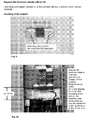
- One embodiment of such mortise lock is shown in Figs. 7 and 8 .
- Fig. 8 shows the door trim from the backside, wherein for clarity purposes the version without wireless connection is shown here as an example.
- Mortise locks known in the prior art generally comprise mechanical sensor means for monitoring and reporting the turning of a key, the position of the door lock bolts (extended or retracted), and the like.
- the building door for use in the elevator system or for being installed while retrofitting an existing elevator system comprises at least one door sensor which is integrated in the building door, such as a sensor comprised in the aforementioned door trim. Further, the building door may comprise at least one recognition device which is integrated in the building door. Still further, the door sensor or the recognition device may be mounted near the building door.
- Said recognition device is provided for identifying a user of the elevator system. For an identified user at least one user recognition signal is communicated to a control system by the recognition device, and may be used for actuating a pre-defined destination call on account of the communicated user recognition signal.
- said door sensor is an electromechanical contact of the building door, and the electromechanical contact communicates a detention of a deadbolt in a lock plate and/or a release of a deadbolt from a lock plate as door signal to the control system, e.g. an elevator control or an electronic controller of the building door.
- the door sensor is a credential reader of the building door, and the credential reader communicates a detection of a credential as door signal to said control system.
- the door sensor is an override sensor, and the override sensor communicates a status of a mechanical key override of the building door as door signal to said control system.
- the door sensor is a lock bolt sensor, and the lock bolt sensor communicates a status of a deadbolt of the building door as door signal to said control system.
- the door sensor is a clutching mechanism for an inside lever and an outside lever of the building door, and the clutching mechanism communicates a movement of the inside and/or outside lever as door signal to said control system.
- the door sensor is an infrared reflective photo sensor, and the infrared reflective photo sensor communicates detection of a user in front of the building door as door signal to said control system.
- the door sensor is a command button on the inner and/or outer side of the building door, and the command button communicates activation of the command button as door signal to said control system. This is of advantage because a plurality of different sensors may be used for detecting the opening and/or closing of a building door.
- the door sensor communicates at least one door signal to a wakeup circuit of the building door; the wakeup circuit collects the door signal as wakeup signal and communicates the wakeup signal to an electronic controller of the building door; and the electronic controller wakes up for a received wakeup signal.
- a door sensor may inform a wakeup circuit about a detected opening and/or closing of a building door.
- the wakeup circuits wakes up the electronic controller of the building door.
- the electronic controller may change to a sleep mode with low or even zero energy consumption, thus increasing the energy autonomy of a battery powered building door.
- the door sensor communicates at least one door signal by way of at least one radio network to the elevator control or the control and/or the recognition device communicates at least one user recognition system by way of at least one radio network to the elevator control or the control.
- the recognition device and/or the door sensor communicates at least one door signal to an electronic controller of the building door; the electronic controller communicates the door signal to a wireless communication unit of the building door; and the wireless communication unit communicates a door signal to the elevator control or the control by way of at least one radio network.
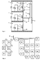
- Figs. 1 to 11 show exemplary embodiments of the invention, wherein Fig. 1 shows an elevator system in a building, Fig. 2 shows a network of the elevator system, and Figs. 3 and 4 show two forms of embodiment of a building door with door sensor for the elevator system.
- the building has several storeys 1, 1', 1" and at least one building door 2', 2" giving access to at least one room.
- the building door 2, 2', 2" is an access door to a dwelling in the building and/or an access door to the building.
- An elevator system is arranged in the building.
- the elevator system has in an elevator shaft, and at least one elevator cage 7 which is connected with at least one counterweight 8 by way of at least one support means 6.
- the support means 6 is placed in motion by at least one elevator drive 5 in friction couple.
- At least one user has access to the elevator cage 7 by way of at least one elevator door 3, 3', 3".
- At least one elevator door 3, 3', 3" is usually arranged in each storey 1, 1', 1".
- the elevator doors 3, 3', 3" of a storey 1, 1', 1" are opened only when an elevator cage 7 stands at this storey 1, 1', 1".
- the opening and closing of the elevator doors 3, 3', 3" takes place by way of a door drive 31.
- At least one elevator control 4 controls the elevator drive 5 and the door drive 31. So that the elevator control 4 knows when an elevator cage 7 has moved into a storey 1, 1', 1", at least one elevator sensor 30, 30', 30" detects movement of the elevator cage 7 into the storey 1, 1', 1".
- the elevator sensor 30, 30', 30" communicates, for a detected movement of the elevator cage 7 into a storey 1, 1', 1", at least one elevator cage signal to the elevator control 4.
- the elevator control 4 opens the elevator door 3, 3', 3" of the storey 1, 1', 1" upon receipt of an elevator cage signal.
- Fig. 2 shows a network of the elevator system.
- the elevator sensors 30, 30', 30" of the elevator shaft as well as recognition devices 90, 90', 90", call input devices 91, 91', 91" and output devices 92, 92', 92" of the terminal 9, 9', 9" as well as the cage sensor 70 of the cage 7 are connected with the elevator control 4 by way of a fixed network.
- the building door 2, 2', 2" comprises an electronic door trim which will be described in more detail in connection with the Figs. 7 to 11 .
- the building door 2, 2', 2" comprises a door leaf, a door frame and a doorstep. Opening and closing of the building door 2, 2', 2" means that the door leaf performs a relative movement with respect to the doorstep. An already minimal relative movement gives recognition to the user's wish to cross the doorstep.
- Radio networks are Wireless Local Area Network (WLAN) according to the Standard IEEE 802.11 and Worldwide Interoperability for Microwave Access (WIMAX) according to the Standard IEEE 802.16 with a range of several 100 metres up to 10 kilometres.
- WLAN Wireless Local Area Network
- WIMAX Worldwide Interoperability for Microwave Access
- a particular wireless communication system sold under the trademark "ZigBee" will be described more in detail in connection with the Figs. 7 to 11 .
- the fixed network comprises, for example, several electrical and/or optical data cables which are laid in the building, for example, under plaster or also suspended in the elevator shaft and thus connect the terminals 9, 9', 9" and the elevator cage 7 with the elevator control 4.
- TCP/IP Transmission Control Protocol / Internet Protocol
- IPX Internet Packet Exchange
- the elevator sensors 30, 30', 30" of the elevator shaft the recognition devices 90, 90', 90", call input devices 91, 91', 91” and output devices 92, 92', 92" of the terminals 9, 9', 9" as well as the cage sensor of the elevator cage 7 can be connected with the elevator control 4 by way of a radio network.
- the door signal indicates to the elevator control 4 a user's wish to use the elevator system.
- a door signal is sufficient for this purpose.
- a door signal is communicated to the elevator control 4 as soon as the building door 2, 2', 2" is opened.
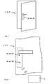
- Figs. 3 and 4 show two forms of embodiment of a building door 2, 2', 2" with door sensor 20, 20', 20" for the elevator system.
- the door sensor 20, 20', 20" is integrated in the building door 2, 2', 2" and/or electronic door trim.
- the door sensor 20, 20', 20" is integrated in the door hardware and thus dissimulated to be imperceptible by users from the outside.
- the door hardware comprises a door pawl and a deadbolt. When the building door 2, 2', 2" is closed the deadbolt is detented in a lock plate of a door frame. Through movement of the door pawl the deadbolt is released from the lock plate of the door frame and the building door 2, 2', 2" is opened.
- the door sensor 20, 20', 20" detects the movement of the door pawl, for example by means of an electromechanical contact. In a first contact setting the deadbolt is detented in the lock plate and in a second contact setting the deadbolt is released from the lock plate. Opening of the building door 2, 2', 2" thus corresponds with movement of the door 4 from a first contact setting to a second contact setting. Closing of the building door 2, 2', 2" thus corresponds with movement of the door pawl from a second contact setting to a first contact setting.
- the door sensor 20, 20', 20" detects this opening or closing of the building door 2, 2', 2" and communicates at least one door signal to the elevator control 4.
- the electromechanical contact may be a magnet and a hall sensor.
- the magnet may be placed on the door pawl, the hall sensor may be placed next to the door pawl. It is also possible, to place the magnet on the door frame and to place the hall sensor on the door leaf. Opening and closing of the building door 2, 2', 2" changes the relative distance between the magnet and the hall sensor, resulting in a difference in the magnetic force from the magnet detected by the hall sensor. Detection of this difference in the magnetic force triggers release of a door signal by the hall sensor.
- the hall sensor is thus one exemplary embodiment of a door sensor. For a person skilled in the art, it is obviously also possible to arrange the door sensor outside a building door 2, 2', 2" or near a building door 2, 2', 2".
- the door sensor can be a movement recording device which is arranged in the door frame of the building door or in a building wall near the building door.
- Other embodiments of door sensors will be described more in detail in the description of the electronic door trim in connection with the Figs. 7 to 11 .
- the recognition device 90, 90', 90" comprises a transmitting and receiving unit for an electromagnetic field and communicates by way of a radio frequency with at least one mobile call input device 10 provided with the user.
- the call input device 10 is, for example, a Radio Frequency Identification (RFID) card with at least one coil, at least one data memory and at least one processor.
- RFID Radio Frequency Identification
- the radio frequency used by the transmitting and receiving unit is, for example, 125 kHz, and 13.56 MHz, 2.45 GHz, etc.
- the call input device 10 takes up, by way of its coil, inductive energy from the electromagnetic field of the recognition device 90, 90', 90" and is thus activated in terms of energy.
- the energy activation takes place automatically as soon as the call input device 10 is disposed in the range of the electromagnetic field from a few centimetres up to a metre.
- the processor reads out an identification code which is filed in the data memory and which is transmitted by way of the coil to the recognition device 90, 90', 90".
- the energy activation of the coil input device 10 and the transmission of the identification code to the recognition device 90, 90', 90" are carried out contactless.
- the recognition device 90, 90', 90" receives the transmitted identification code by the receiving unit and electronically prepares it.
- the recognition device 90, 90', 90" comprises at least one further data memory and at least one further processor.
- the transmitted identification code is recognised by the further processor in accordance with the recognition protocol.
- the recognised identification code is communicated to the elevator control as a user recognition signal.
- the elevator control 4 In the form of embodiment of a building door 2, 2', 2" according to Fig. 3 only one door signal is communicated to the elevator control 4, in the form of embodiment of a building door 2, 2', 2" according to Fig. 4 the communication of a door signal and a user recognition signal to the elevator control 4 is carried out.
- the elevator control 4 defines the storey of the communicated door signal as start storey and actuates a start call for an elevator cage 7 on the start storey.
- a destination call .e.g a destination call pre-defined for the start storey, is actuated by the elevator control 4.
- the elevator control 4 On additional communication of a user recognition signal to the elevator control 4 the elevator control 4 identifies the communicated user recognition signal.
- the elevator control 4 comprises for that purpose at least one user data memory and at least one computing processor.
- the computing processor identifies the communicated user recognition signal by a pre-defined destination call filed in the user data memory.
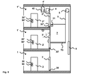
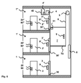
- Figs. 5 and 6 show a retrofitted elevator system in a building.
- An existing elevator comprising like feature of the elevator in Fig. 1 is arranged in the building.
- at least one door sensor 20, 20', 20" is installed in or near at least one building door 2, 2', 2" or the entire existing building door 2, 2', 2" is replaced by a building door 2, 2', 2" with an integrated door sensor 20, 20', 20".
- at least one control 4' is installed. The control 4' communicates with the door sensor 20, 20', 20" and the elevator control 4.
- the door sensor 20, 20', 20" detects opening of the building door 2, 2', 2" and communicates, for a detected opening of the building door 2, 2', 2", at least one door signal to the control 4'.
- the control 4' defines the storey 1, 1', 1" of the communicated door signal as start storey and actuates a start call for the elevator cage 7 to the start storey.
- the control 4' is connected with at least one signal input of the elevator control 4 and actuates the start call by way of this signal input.
- At least one recognition device 90, 90', 90" is installed in or near at least one existing building door 2, 2', 2" or the entire existing building door 2, 2', 2" is replaced by a building door 2, 2', 2" comprising an integrated recognition device 90, 90', 90".
- the recognition device 90, 90', 90" identifies the user and communicates, for an identified user, at least one user recognition signal to the control 4'.
- the control 4' actuates a pre-defined destination call, which is filed for the communicated user recognition signal, for the elevator cage 7 to a destination storey.
- At least one antenna 40 is installed.
- the door sensor 20, 20', 20" communicates at least one door signal by way of at least one radio network to the control 4' and/or the recognition device 90, 90', 90" communicates at least one user recognition signal to the control 4' by way of at least one radio network.
- At least one terminal 9, 9', 9" is arranged on each storey 1, 1', 1" in stationary position near an existing elevator door 3, 3', 3" and/or a terminal 9 is arranged in the elevator cage 7.
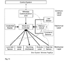
- the components of the electronic door trim according to the invention and the interaction of these components are now described in more detail with reference to the block diagram shown in Fig. 11 .
- the components that are particularly relevant for the invention and that generally are not present in a known electronic door trim are the Wireless Communication Unit, the Lock Bolt Sensor, the Inside Lever, and the Override Sensor.
- the Command Buttons may also be included in an electronic door trim according to the invention.
- the Wireless Communication Unit wirelessly communicates with a Control System which sends commands to the door trim system and which gets reports about events at the door.
- the Wireless Communication Unit transmits commands and events by an encrypted wireless connection.
- the connection can be built by one control system and many door systems.
- a user sensor detects a user in front of the door system. This may be done by detection of a credential close to a credential reader or by any other technical possibility to detect a user (Infrared reflective photo sensor).
- the credential reader reads credential data which may influence the decision of an electronic controller.
- the process of the credential reader's reading a credential corresponds to the recognition device 90, 90', 90" for the recognition of an identification code which has been previously described.
- a Wakeup Circuit collects a wakeup signal from different sensors (arrowed dotted lines in the diagram of Fig. 11 ) to wake up the electronic controller.
- the Wakeup Circuit plays an important role to keep an energy consumption of the door system at a minimum.
- the lock bolt sensor detects and represents the status of the deadbolt (locked or unlocked).
- the lock bolt sensor may be an electromechanical contact in the embodiment of a magnet and corresponding hall sensor, where the magnet on the retracted lockbolt magnetizes the hall sensor which triggers release of a door signal by the hall sensor.
- the lock bolt sensor may be an electric contact which is closed for a retracted lockbolt and open for an extended lockbolt. An open electric contact triggers release of a door signal.
- the override sensor detects and represents the status of the mechanical key override (by turning a key in a mechanical locking cylinder).
- the override sensor may be an electric contact which is closed for no key in the mechanical locking cylinder and open for an inserted and turned key in the mechanical locking cylinder. An open electric contact triggers release of a door signal. If a protected door is opened by an override key, the override sensor will immediately forward and report this information to a monitoring and/or control unit for security reasons in order to prevent unauthorized opening of the door.
- a clutching mechanism for the inside lever and the outside lever of the door allows a signal indicative of a movement of the inner and/or outer lever to be sent to the mechanical lock to open the door.
- the inner lever can trigger the wakeup circuit.
- a movement of the inner lever is reported to the electronics and/or a monitoring/control unit, particularly for security reasons in order to prevent unauthorized opening of the door and/or the leaving of the protected room by an unauthorized person.
- the clutching mechanism may be a microswitch which is activated or deactivated by a movement of the inner lever. For example, an activated microswitch triggers release of a door signal.
- command buttons may be represented by standard push buttons on the inner or outer side of any building door 2, 2', 2". These buttons may initiate commands to the electronic controller, or commands are sent by wireless communication to the control system, for example to initiate actions within a higher or super-ordinate communication system, e.g. initiating an alarm or calling a front door security service. For example, an activated command button triggers release of a door signal.
- the electronic door trim system operates wireless and therefore does not require extensive and complex cable wiring as required for prior art systems. For these reasons, the electronic door trim system operates more safely, reliable and secure and does not tend to fail.
- the electronic door trim system allows for the complete monitoring of a protected door, particularly with respect to opening and/or closing the door by authorized or non-authorized persons at authorized or non-authorized times. Besides, the system can determine whether a protected door after its opening is closed again, as required, or whether it stays open, for example by means of not permitted, irregular blocking means (such as a wedge pushed underneath the door).
- Figs. 9a to 9d show the mounting of the wireless device with an adapter to the door trim.
- Fig. 10 is a perspective view of a door model within which the wireless functions of the electronic door trim system may be utilized.
Landscapes
- Engineering & Computer Science (AREA)
- Automation & Control Theory (AREA)
- Computer Networks & Wireless Communication (AREA)
- Lock And Its Accessories (AREA)
- Elevator Door Apparatuses (AREA)
Abstract
Description
- The invention relates to an electronic door trim, particularly an electronic door trim for use in an elevator system. The invention also relates to an elevator system comprising at least one building door with an integrated electronic door trim and building door comprising said electronic door trim, the building door particularly provided for being used in an elevator system.
- Electronic door trims are used, amongst others, in conjunction with access-control systems, and they are regularly combined with components of architectural hardware, door locks, door closers, door frames and doors in general. Electronic door trims are for example used for monitoring and controlling the access of authorized or non-authorized people to security sensitive areas.
- Such electronic door trims are for example known under the trademarks and/or type designations PEGASYS and 6020 System, which are manufactured and sold by the applicant. Details of this known system are described in the User Manual "Pegasys Offline Terminals and the 6020 System, Version 1.56", issued by the applicant dated January 25, 2006.
- These electronic door trim systems control the unlocking and opening or blocking, respectively, of a door or a similar device for an authorized or non-authorized access. Therein, the electronic door trim systems are for example controlled and activated by the use of an electronic chip card, by the entry of a specific code over a keyboard, or similar devices. Further, electronic door trim systems comprise a battery driven electronic control unit that monitors and controls, amongst others, the status of contacts, and that activates and engages or disengages, respectively, levers and bolts by a coupling or clutch within the lock. For the operation of these components, such systems generally require extensive and complex wiring with cables which has to be integrated with the associated contacts into the lock and/or the door and/or the door frame. The wiring is particularly also required for the data transfer and the communication between the individual components of the control system. Thus, these systems are regarded as being offline devices.
- A problem underlying such known electronic door trim systems is the secure and reliable operation of the systems, as said complex wiring may tend to have defects and errors, which may in turn result in a partial or complete failure of the overall system. Therefore, it is an aim of the invention to overcome these problems and to provide an improved electronic door trim system.
- These objects are addressed by the invention as defined in the independent claims, defining an improved electronic door trim system, a building door, particularly a building door for use in an elevator system, comprising such electronic door trim system, and elevator system comprising said integrated electronic door trim system and/or a least one door with an integrated electronic door trim system. With such an electronic door trim, a lock is operating like an online door which supervises the lock bolt status contact, and is online connected to an access control system.
- In embodiments, an electronic door trim is equipped with a battery driven wireless connection on the base of a radio transmission technology. The respective wireless communication units can be operated with various frequencies, wherein one known system is the wireless LAN technology as used for Internet access in private or public surroundings. Another wireless communication system, which is suitable for an embodiment of the door trim, is a system sold under the trademark "ZigBee". This known system is particularly well suited for a battery driven operation, considering the limited life time of a battery. This system typically has a range of 30 to 100 Meters. However, also other, comparable systems may be used for the purposes of the invention.
- The use of said wireless communication units offers the advantage that the door trims will no longer be offline, but get the capability to react online by the wireless connection to a host computer (as, e.g. in the PEGASYS system, the access control System IF 6020). The wireless communication systems (such as e.g. the "ZigBee" connection) typically put only 5% of additional load to the battery.
- To allow the full door control, a mortise lock is added to the wireless connected electronic door trim. This offers status contacts for the lever handling from inside a room, a status of a mechanical override by a mechanical locking cylinder, and a status of the dead bolt.
- These status contacts are attached to the electronics of the electronic door trim by an adapter board (see
Figs. 9a to 9d , as further discussed below). - In embodiments, a self locking lock with panic function, as for example manufactured and sold by Cisa S.p.A. of Faenza, Italy, is utilised as said mortise lock. One embodiment of such mortise lock is shown in
Figs. 7 and 8 . Therein,Fig. 8 shows the door trim from the backside, wherein for clarity purposes the version without wireless connection is shown here as an example. Mortise locks known in the prior art generally comprise mechanical sensor means for monitoring and reporting the turning of a key, the position of the door lock bolts (extended or retracted), and the like. - The building door for use in the elevator system or for being installed while retrofitting an existing elevator system comprises at least one door sensor which is integrated in the building door, such as a sensor comprised in the aforementioned door trim. Further, the building door may comprise at least one recognition device which is integrated in the building door. Still further, the door sensor or the recognition device may be mounted near the building door.
- Said recognition device is provided for identifying a user of the elevator system. For an identified user at least one user recognition signal is communicated to a control system by the recognition device, and may be used for actuating a pre-defined destination call on account of the communicated user recognition signal.
- In one embodiment said door sensor is an electromechanical contact of the building door, and the electromechanical contact communicates a detention of a deadbolt in a lock plate and/or a release of a deadbolt from a lock plate as door signal to the control system, e.g. an elevator control or an electronic controller of the building door. Advantageously the door sensor is a credential reader of the building door, and the credential reader communicates a detection of a credential as door signal to said control system. Advantageously the door sensor is an override sensor, and the override sensor communicates a status of a mechanical key override of the building door as door signal to said control system. Advantageously the door sensor is a lock bolt sensor, and the lock bolt sensor communicates a status of a deadbolt of the building door as door signal to said control system. Advantageously the door sensor is a clutching mechanism for an inside lever and an outside lever of the building door, and the clutching mechanism communicates a movement of the inside and/or outside lever as door signal to said control system. Advantageously the door sensor is an infrared reflective photo sensor, and the infrared reflective photo sensor communicates detection of a user in front of the building door as door signal to said control system. Advantageously the door sensor is a command button on the inner and/or outer side of the building door, and the command button communicates activation of the command button as door signal to said control system. This is of advantage because a plurality of different sensors may be used for detecting the opening and/or closing of a building door.
- Advantageously the door sensor communicates at least one door signal to a wakeup circuit of the building door; the wakeup circuit collects the door signal as wakeup signal and communicates the wakeup signal to an electronic controller of the building door; and the electronic controller wakes up for a received wakeup signal.
- This is of advantage because a door sensor may inform a wakeup circuit about a detected opening and/or closing of a building door. Upon collection of a door signal, the wakeup circuits wakes up the electronic controller of the building door. When no door signal is collected by the wakeup circuit, the electronic controller may change to a sleep mode with low or even zero energy consumption, thus increasing the energy autonomy of a battery powered building door.
- Advantageously at least one antenna is installed. Advantageously the door sensor communicates at least one door signal by way of at least one radio network to the elevator control or the control and/or the recognition device communicates at least one user recognition system by way of at least one radio network to the elevator control or the control. Advantageously the recognition device and/or the door sensor communicates at least one door signal to an electronic controller of the building door; the electronic controller communicates the door signal to a wireless communication unit of the building door; and the wireless communication unit communicates a door signal to the elevator control or the control by way of at least one radio network. The laying of data cables of a fixed network is thus not necessary for having the aforementioned data transferred.
- Examples of embodiment of the invention are explained in more detail by way of the figures, for which purpose in partly schematic form:
- Fig. 1
- shows a partially sectioned view of a part of an elevator system in a building;
- Fig. 2
- shows a partially sectioned view of a part of a network of an elevator system according to
Fig. 1 ; - Fig. 3
- shows a view of a part of a first form of embodiment of a building door with door sensor for the elevator system according to
Fig. 1 ; - Fig. 4
- shows a view of part of a second form of embodiment of a building door with door sensor for the elevator system according to
Fig. 1 ; - Fig. 5
- shows a partially sectioned view of apart of a retrofitted elevator system in a building;
- Fig. 6
- shows a partially sectioned view of a part of a further retrofitted elevator system in a building according to
Fig. 5 ; - Figs. 7 and 8
- show an embodiment of a mortise lock used in connection with the electronic door trim of the invention;
- Figs. 9a to 9d
- show the mounting of the wireless device according to the invention with an adapter to the door trim;
- Fig. 10
- shows two perspective views of a door model within which the wireless functions according to the invention may be utilized; and
- Fig. 11
- is a block diagram showing the components of the electronic door trim according to the invention.
-
Figs. 1 to 11 show exemplary embodiments of the invention, whereinFig. 1 shows an elevator system in a building,Fig. 2 shows a network of the elevator system, andFigs. 3 and 4 show two forms of embodiment of a building door with door sensor for the elevator system. - According to
Fig. 1 the building hasseveral storeys building door 2', 2" giving access to at least one room. Thebuilding door elevator cage 7 which is connected with at least onecounterweight 8 by way of at least one support means 6. For movement ofelevator cage 7 andcounterweight 8 the support means 6 is placed in motion by at least oneelevator drive 5 in friction couple. At least one user has access to theelevator cage 7 by way of at least oneelevator door elevator door storey elevator doors storey elevator cage 7 stands at thisstorey elevator doors door drive 31. At least oneelevator control 4 controls theelevator drive 5 and thedoor drive 31. So that theelevator control 4 knows when anelevator cage 7 has moved into astorey elevator sensor elevator cage 7 into thestorey elevator sensor elevator cage 7 into astorey elevator control 4. Theelevator control 4 opens theelevator door storey -
Fig. 2 shows a network of the elevator system. Theelevator sensors recognition devices input devices output devices terminal cage sensor 70 of thecage 7 are connected with theelevator control 4 by way of a fixed network. - The
building door Figs. 7 to 11 . Thebuilding door building door -
Door sensors building door recognition devices building doors antenna 40 of theelevator control 4 by way of a radio network. Known radio networks are Wireless Local Area Network (WLAN) according to the Standard IEEE 802.11 and Worldwide Interoperability for Microwave Access (WIMAX) according to the Standard IEEE 802.16 with a range of several 100 metres up to 10 kilometres. A particular wireless communication system sold under the trademark "ZigBee" will be described more in detail in connection with theFigs. 7 to 11 . Not only the fixed network, but also the radio network allows a bidirectional communication according to known and proven network protocols such as the Transmission Control Protocol / Internet Protocol (TCP/IP) or Internet Packet Exchange (IPX). The fixed network comprises, for example, several electrical and/or optical data cables which are laid in the building, for example, under plaster or also suspended in the elevator shaft and thus connect theterminals elevator cage 7 with theelevator control 4. Obviously also theelevator sensors recognition devices input devices output devices terminals elevator cage 7 can be connected with theelevator control 4 by way of a radio network. - The door signal indicates to the elevator control 4 a user's wish to use the elevator system. A door signal is sufficient for this purpose. For example, a door signal is communicated to the
elevator control 4 as soon as thebuilding door -
Figs. 3 and 4 show two forms of embodiment of abuilding door door sensor door sensor building door door sensor building door building door door sensor building door door 4 from a first contact setting to a second contact setting. Closing of thebuilding door door sensor building door elevator control 4. - The electromechanical contact may be a magnet and a hall sensor. The magnet may be placed on the door pawl, the hall sensor may be placed next to the door pawl. It is also possible, to place the magnet on the door frame and to place the hall sensor on the door leaf. Opening and closing of the
building door building door building door Figs. 7 to 11 . - In the form of embodiment of the
building door Fig. 4 at least onerecognition device building door recognition device call input device 10 provided with the user. Thecall input device 10 is, for example, a Radio Frequency Identification (RFID) card with at least one coil, at least one data memory and at least one processor. The radio frequency used by the transmitting and receiving unit is, for example, 125 kHz, and 13.56 MHz, 2.45 GHz, etc. Thecall input device 10 takes up, by way of its coil, inductive energy from the electromagnetic field of therecognition device call input device 10 is disposed in the range of the electromagnetic field from a few centimetres up to a metre. As soon as therecognition device recognition device coil input device 10 and the transmission of the identification code to therecognition device recognition device recognition device - Whereas in the form of embodiment of a
building door Fig. 3 only one door signal is communicated to theelevator control 4, in the form of embodiment of abuilding door Fig. 4 the communication of a door signal and a user recognition signal to theelevator control 4 is carried out. On communication of only a door signal to theelevator control 4, theelevator control 4 defines the storey of the communicated door signal as start storey and actuates a start call for anelevator cage 7 on the start storey. A destination call, .e.g a destination call pre-defined for the start storey, is actuated by theelevator control 4. On additional communication of a user recognition signal to theelevator control 4 theelevator control 4 identifies the communicated user recognition signal. Theelevator control 4 comprises for that purpose at least one user data memory and at least one computing processor. The computing processor identifies the communicated user recognition signal by a pre-defined destination call filed in the user data memory. -
Figs. 5 and6 show a retrofitted elevator system in a building. An existing elevator comprising like feature of the elevator inFig. 1 is arranged in the building. For retrofitting the existing elevator, at least onedoor sensor building door building door building door integrated door sensor door sensor elevator control 4. Thedoor sensor building door building door storey elevator cage 7 to the start storey. For example, the control 4' is connected with at least one signal input of theelevator control 4 and actuates the start call by way of this signal input. Alternatively, it is obviously also possible to replace theformer elevator control 4 by anew elevator control 4 according to the form of embodiment ofFigs. 1 and 2 , whichnew elevator control 4 fulfils the functions of theprevious elevator control 4 and those of the control 4'. - Still further, for retrofitting the elevator, at least one
recognition device building door building door building door integrated recognition device recognition device elevator cage 7 to a destination storey. - For retrofitting the existing elevator installation to an elevator system, at least one
antenna 40 is installed. Thedoor sensor recognition device - Also, for retrofitting the existing elevator to an elevator installation, at least one
terminal storey elevator door terminal 9 is arranged in theelevator cage 7. - The components of the electronic door trim according to the invention and the interaction of these components are now described in more detail with reference to the block diagram shown in
Fig. 11 . The components that are particularly relevant for the invention and that generally are not present in a known electronic door trim (such as the PEGASYS system) are the Wireless Communication Unit, the Lock Bolt Sensor, the Inside Lever, and the Override Sensor. As an additional, optional feature, the Command Buttons may also be included in an electronic door trim according to the invention. - The Wireless Communication Unit wirelessly communicates with a Control System which sends commands to the door trim system and which gets reports about events at the door. The Wireless Communication Unit transmits commands and events by an encrypted wireless connection. The connection can be built by one control system and many door systems. A user sensor detects a user in front of the door system. This may be done by detection of a credential close to a credential reader or by any other technical possibility to detect a user (Infrared reflective photo sensor). The credential reader reads credential data which may influence the decision of an electronic controller. The process of the credential reader's reading a credential corresponds to the
recognition device - A Wakeup Circuit collects a wakeup signal from different sensors (arrowed dotted lines in the diagram of
Fig. 11 ) to wake up the electronic controller. The Wakeup Circuit plays an important role to keep an energy consumption of the door system at a minimum. - The lock bolt sensor detects and represents the status of the deadbolt (locked or unlocked). The lock bolt sensor may be an electromechanical contact in the embodiment of a magnet and corresponding hall sensor, where the magnet on the retracted lockbolt magnetizes the hall sensor which triggers release of a door signal by the hall sensor. The lock bolt sensor may be an electric contact which is closed for a retracted lockbolt and open for an extended lockbolt. An open electric contact triggers release of a door signal.
- The override sensor detects and represents the status of the mechanical key override (by turning a key in a mechanical locking cylinder). The override sensor may be an electric contact which is closed for no key in the mechanical locking cylinder and open for an inserted and turned key in the mechanical locking cylinder. An open electric contact triggers release of a door signal. If a protected door is opened by an override key, the override sensor will immediately forward and report this information to a monitoring and/or control unit for security reasons in order to prevent unauthorized opening of the door.
- A clutching mechanism for the inside lever and the outside lever of the door allows a signal indicative of a movement of the inner and/or outer lever to be sent to the mechanical lock to open the door. The inner lever can trigger the wakeup circuit. A movement of the inner lever is reported to the electronics and/or a monitoring/control unit, particularly for security reasons in order to prevent unauthorized opening of the door and/or the leaving of the protected room by an unauthorized person. The clutching mechanism may be a microswitch which is activated or deactivated by a movement of the inner lever. For example, an activated microswitch triggers release of a door signal.
- As an optional feature, command buttons may be represented by standard push buttons on the inner or outer side of any
building door - The electronic door trim system operates wireless and therefore does not require extensive and complex cable wiring as required for prior art systems. For these reasons, the electronic door trim system operates more safely, reliable and secure and does not tend to fail. The electronic door trim system allows for the complete monitoring of a protected door, particularly with respect to opening and/or closing the door by authorized or non-authorized persons at authorized or non-authorized times. Besides, the system can determine whether a protected door after its opening is closed again, as required, or whether it stays open, for example by means of not permitted, irregular blocking means (such as a wedge pushed underneath the door).
-
Figs. 9a to 9d show the mounting of the wireless device with an adapter to the door trim.Fig. 10 is a perspective view of a door model within which the wireless functions of the electronic door trim system may be utilized.
Claims (7)
- An electronic door trim for controlling an unlocking and opening or locking and closing, respectively, of a door or a similar device, particularly a building door (2, 2', 2") in a building comprising an elevator system, for an authorized or non-authorized access to a protected area; wherein said electronic door trim comprises- a control system which sends commands to the door and which receives reports about events at the door;- a user sensor which detects a user in front of the door by detection of credential data, wherein the detected credential data influence the decision of an electronic controller; and- a wakeup circuit which collects a wakeup signal from different sensors to wake up the electronic controller.
- The electronic door trim of claim 1, characterized by- a wireless communication unit which communicates with the control system and which transmits commands and events by an encrypted wireless connection;- a lock bolt sensor which detects and represents the locked or unlocked status of a deadbolt;- an override sensor which detects and represents the status of a mechanical override key;- an inside lever and an outside lever for the door; and- a clutching mechanism for the inside lever and the outside lever which sends the movement of the inner and/or outer levers to the mechanical lock of the door to open the door.
- The electronic door trim of claim 1 or claim 2, wherein the inner lever triggers the wakeup circuit.
- The electronic door trim according to any one of the preceding claims, further comprising command buttons which initiate commands to the electronic controller or commands that are sent by wireless communication to the control system.
- An elevator system in a building with at least two storeys (1, 1', 1 "); at least one elevator door (3, 3', 3"); and at least one building door (2, 2', 2");
characterized in that- the building door (2, 2', 2") comprises at least one door sensor (20, 20', 20") integrated in an electronic door trim according to any one of the preceding claims;- the door sensor (20, 20', 20") detects opening and/or closing of the building door (2, 2', 2") and for a detected opening and/or closing of the building door (2, 2', 2") communicates at least one door signal to at least one elevator control (4);- the elevator control (4) defines the storey (1, 1', 1") of the communicated door signal as start storey,- the elevator control (4) actuates a start call for an elevator cage (7) to the start storey;- at least one elevator sensor (30, 30', 30") detects the movement of the elevator cage (7) into the start storey;- the elevator sensor (30, 30', 30") communicates, for a detected movement of the elevator cage (7) into the start storey, at least one elevator cage signal to the elevator control (4); and- the elevator control (4), upon receipt of an elevator cage signal, opens the elevator door (3, 3', 3") of the start storey. - Building door (2, 2', 2") for use in an elevator system according to claim 5, characterized in
comprising at least one door sensor (20, 20', 20") integrated in an electronic door trim according to any one of claims 1 to 4 an in that said door sensor (20, 20', 20") is selected from a group consisting of:an electromechanical contact of the building door (2, 2', 2"), wherein said electromechanical contact communicates a detention of a deadbolt in a lock plate and/or a release of a deadbolt from a lock plate as door signal to an electronic controller of the building door (2, 2', 2")a credential reader of the building door (2, 2', 2"), wherein said credential reader communicates a detection of a credential as door signal to an electronic controller of the building door (2, 2', 2")an override sensor, wherein said override sensor communicates a status of a mechanical key override of the building door (2, 2', 2") as door signal to an electronic controller of the building door (2, 2', 2")a lock bolt sensor, wherein said lock bolt sensor communicates a status of a deadbolt of the building door (2, 2', 2") as door signal to an electronic controller of the building door (2, 2', 2")a clutching mechanism for an inside lever and an outside lever of the building door (2, 2', 2"), wherein said clutching mechanism communicates a movement of the inside and/or outside lever as door signal to an electronic controller of the building door (2, 2', 2")an infrared reflective photo sensor, wherein said infrared reflective photo sensor communicates detection of a user in front of the building door (2, 2', 2") as door signal to an electronic controller of the building door (2, 2', 2")a command button on the inner and/or outer side of the building door (2, 2', 2"),wherein said command button communicates activation of the command button as door signal to an electronic controller of the building door (2, 2', 2"). - Building door according to claim 6 in an elevator system according to claim 5, characterized in that the door sensor (20, 20', 20") communicates at least one door signal to the elevator control (4) or the control (4') by way of at least one radio network
and/or that the door sensor (20, 20', 20") communicates at least one door signal to the wakeup circuit of the building door (2, 2', 2"); that the wakeup circuit collects the door signal as wakeup signal and communicates the wakeup signal to an electronic controller of the building door (2, 2', 2"); and that the electronic controller wakes up for a received wakeup signal
and/or that the door sensor (20, 20', 20") communicates at least one door signal to an electronic controller of the building door (2, 2', 2"); that the electronic controller communicates the door signal to a wireless communication unit of the building door (2, 2', 2"); and that the wireless communication unit communicates a door signal to the elevator control (4) or the control (4') by way of at least one radio network.
Priority Applications (1)
| Application Number | Priority Date | Filing Date | Title |
|---|---|---|---|
| EP20110179943 EP2392533B1 (en) | 2008-04-28 | 2009-04-28 | Electronic door trim, elevator system comprising a building door having said electronic door trim integrated therein, and building door comprising said electronic door trim |
Applications Claiming Priority (4)
| Application Number | Priority Date | Filing Date | Title |
|---|---|---|---|
| PCT/EP2008/055193 WO2009132690A1 (en) | 2008-04-28 | 2008-04-28 | Method for using a lift system, lift system suitable for such a method, and method for equipping such a lift system |
| DE102008050563 | 2008-10-06 | ||
| EP20110179943 EP2392533B1 (en) | 2008-04-28 | 2009-04-28 | Electronic door trim, elevator system comprising a building door having said electronic door trim integrated therein, and building door comprising said electronic door trim |
| EP09737611A EP2271571A2 (en) | 2008-04-28 | 2009-04-28 | Method of using an elevator system, elevator system for such a method and method of retrofitting such an elevator system and electronic door trim |
Related Parent Applications (2)
| Application Number | Title | Priority Date | Filing Date |
|---|---|---|---|
| EP09737611A Division EP2271571A2 (en) | 2008-04-28 | 2009-04-28 | Method of using an elevator system, elevator system for such a method and method of retrofitting such an elevator system and electronic door trim |
| EP09737611.5 Division | 2009-04-28 |
Publications (3)
| Publication Number | Publication Date |
|---|---|
| EP2392533A2 true EP2392533A2 (en) | 2011-12-07 |
| EP2392533A3 EP2392533A3 (en) | 2012-05-23 |
| EP2392533B1 EP2392533B1 (en) | 2014-07-16 |
Family
ID=43304180
Family Applications (2)
| Application Number | Title | Priority Date | Filing Date |
|---|---|---|---|
| EP09737611A Withdrawn EP2271571A2 (en) | 2008-04-28 | 2009-04-28 | Method of using an elevator system, elevator system for such a method and method of retrofitting such an elevator system and electronic door trim |
| EP20110179943 Active EP2392533B1 (en) | 2008-04-28 | 2009-04-28 | Electronic door trim, elevator system comprising a building door having said electronic door trim integrated therein, and building door comprising said electronic door trim |
Family Applications Before (1)
| Application Number | Title | Priority Date | Filing Date |
|---|---|---|---|
| EP09737611A Withdrawn EP2271571A2 (en) | 2008-04-28 | 2009-04-28 | Method of using an elevator system, elevator system for such a method and method of retrofitting such an elevator system and electronic door trim |
Country Status (1)
| Country | Link |
|---|---|
| EP (2) | EP2271571A2 (en) |
Cited By (1)
| Publication number | Priority date | Publication date | Assignee | Title |
|---|---|---|---|---|
| US20220106167A1 (en) * | 2019-03-28 | 2022-04-07 | Inventio Ag | Automatically controlled door assembly as an elevator level door of an elevator system |
Family Cites Families (2)
| Publication number | Priority date | Publication date | Assignee | Title |
|---|---|---|---|---|
| US4837822A (en) * | 1986-04-08 | 1989-06-06 | Schlage Lock Company | Cryptographic based electronic lock system and method of operation |
| DE10028176A1 (en) * | 2000-06-09 | 2001-12-13 | Michael Dorn | Self-operating deadlock for e.g. hotels includes blocking device operated by remote control, to block or release latch operation |
-
2009
- 2009-04-28 EP EP09737611A patent/EP2271571A2/en not_active Withdrawn
- 2009-04-28 EP EP20110179943 patent/EP2392533B1/en active Active
Non-Patent Citations (1)
| Title |
|---|
| "User Manual", 25 January 2006, article "Pegasys Offline Terminals and the 6020 System, Version 1.56" |
Cited By (1)
| Publication number | Priority date | Publication date | Assignee | Title |
|---|---|---|---|---|
| US20220106167A1 (en) * | 2019-03-28 | 2022-04-07 | Inventio Ag | Automatically controlled door assembly as an elevator level door of an elevator system |
Also Published As
| Publication number | Publication date |
|---|---|
| EP2392533A3 (en) | 2012-05-23 |
| EP2392533B1 (en) | 2014-07-16 |
| EP2271571A2 (en) | 2011-01-12 |
Similar Documents
| Publication | Publication Date | Title |
|---|---|---|
| US20110100762A1 (en) | Method of using an elevator system, elevator system for such a method and method of retrofitting such an elevator system and electronic door trim | |
| CN102015505B (en) | Method of using elevator system, elevator system used in the method and method of retrofitting the elevator system | |
| US7967197B2 (en) | Integrated online door via electronic door handle | |
| US7388467B2 (en) | System and method for determining a state of a door | |
| US7446644B2 (en) | Universal hands free key and lock system | |
| CN112469653B (en) | Remote control device and remote control system | |
| EP0846312A1 (en) | Electromagnetically managed latching exit bar | |
| HK1250827A1 (en) | Electronic lock for furniture, cabinets or lockers | |
| CN102587734B (en) | Electromechanical dual-controlled intelligent lockset and door lock system | |
| WO2016196578A1 (en) | Access control device commissioning | |
| WO2010046677A1 (en) | Door or window security system for mounting at a door or window frame | |
| WO2001086097A2 (en) | Wireless electromechanical lock | |
| US20060059963A1 (en) | Wireless access control system including wireless exit kit (''WEXK'') with panic bar | |
| EP2392533B1 (en) | Electronic door trim, elevator system comprising a building door having said electronic door trim integrated therein, and building door comprising said electronic door trim | |
| AU2016376483B2 (en) | Access system with substitute/alternative function | |
| WO2010022457A9 (en) | A safe secure lock | |
| EP1888864A1 (en) | Lock assembly | |
| JP2006138162A (en) | Security system | |
| JP7755368B2 (en) | Information processing device and program | |
| JP2006144440A (en) | Security system | |
| JP2006097444A (en) | Door lock and security system using the same | |
| EP4533429A1 (en) | Video doorbell device | |
| CN107657690A (en) | A kind of anti-theft door system of automatic identification opening ways | |
| JP2015014128A (en) | Guard signal output device | |
| JPH0877480A (en) | Building management system association type key storage device |
Legal Events
| Date | Code | Title | Description |
|---|---|---|---|
| 17P | Request for examination filed |
Effective date: 20110902 |
|
| AC | Divisional application: reference to earlier application |
Ref document number: 2271571 Country of ref document: EP Kind code of ref document: P |
|
| AK | Designated contracting states |
Kind code of ref document: A2 Designated state(s): AT BE BG CH CY CZ DE DK EE ES FI FR GB GR HR HU IE IS IT LI LT LU LV MC MK MT NL NO PL PT RO SE SI SK TR |
|
| PUAI | Public reference made under article 153(3) epc to a published international application that has entered the european phase |
Free format text: ORIGINAL CODE: 0009012 |
|
| RIN1 | Information on inventor provided before grant (corrected) |
Inventor name: KLOSTERMEIER, MANFRED Inventor name: GERSTENKORN, BERNHARD Inventor name: VOSSELER, JUERGEN Inventor name: FRIEDLI, PAUL Inventor name: SCHUSTER, KILIAN |
|
| PUAL | Search report despatched |
Free format text: ORIGINAL CODE: 0009013 |
|
| AK | Designated contracting states |
Kind code of ref document: A3 Designated state(s): AT BE BG CH CY CZ DE DK EE ES FI FR GB GR HR HU IE IS IT LI LT LU LV MC MK MT NL NO PL PT RO SE SI SK TR |
|
| RIC1 | Information provided on ipc code assigned before grant |
Ipc: E05B 1/00 20060101ALI20120413BHEP Ipc: B66B 1/46 20060101AFI20120413BHEP |
|
| 17Q | First examination report despatched |
Effective date: 20120523 |
|
| GRAP | Despatch of communication of intention to grant a patent |
Free format text: ORIGINAL CODE: EPIDOSNIGR1 |
|
| INTG | Intention to grant announced |
Effective date: 20140206 |
|
| RIC1 | Information provided on ipc code assigned before grant |
Ipc: E05B 45/12 20060101ALI20140127BHEP Ipc: E05B 15/02 20060101ALI20140127BHEP Ipc: B66B 1/46 20060101AFI20140127BHEP Ipc: E05B 1/00 20060101ALI20140127BHEP |
|
| GRAS | Grant fee paid |
Free format text: ORIGINAL CODE: EPIDOSNIGR3 |
|
| GRAA | (expected) grant |
Free format text: ORIGINAL CODE: 0009210 |
|
| AC | Divisional application: reference to earlier application |
Ref document number: 2271571 Country of ref document: EP Kind code of ref document: P |
|
| AK | Designated contracting states |
Kind code of ref document: B1 Designated state(s): AT BE BG CH CY CZ DE DK EE ES FI FR GB GR HR HU IE IS IT LI LT LU LV MC MK MT NL NO PL PT RO SE SI SK TR |
|
| REG | Reference to a national code |
Ref country code: GB Ref legal event code: FG4D |
|
| REG | Reference to a national code |
Ref country code: CH Ref legal event code: EP |
|
| REG | Reference to a national code |
Ref country code: IE Ref legal event code: FG4D |
|
| REG | Reference to a national code |
Ref country code: AT Ref legal event code: REF Ref document number: 677487 Country of ref document: AT Kind code of ref document: T Effective date: 20140815 |
|
| REG | Reference to a national code |
Ref country code: DE Ref legal event code: R096 Ref document number: 602009025425 Country of ref document: DE Effective date: 20140904 |
|
| REG | Reference to a national code |
Ref country code: ES Ref legal event code: FG2A Ref document number: 2516890 Country of ref document: ES Kind code of ref document: T3 Effective date: 20141031 |
|
| REG | Reference to a national code |
Ref country code: NL Ref legal event code: T3 |
|
| REG | Reference to a national code |
Ref country code: LT Ref legal event code: MG4D |
|
| PG25 | Lapsed in a contracting state [announced via postgrant information from national office to epo] |
Ref country code: BG Free format text: LAPSE BECAUSE OF FAILURE TO SUBMIT A TRANSLATION OF THE DESCRIPTION OR TO PAY THE FEE WITHIN THE PRESCRIBED TIME-LIMIT Effective date: 20141016 Ref country code: NO Free format text: LAPSE BECAUSE OF FAILURE TO SUBMIT A TRANSLATION OF THE DESCRIPTION OR TO PAY THE FEE WITHIN THE PRESCRIBED TIME-LIMIT Effective date: 20141016 Ref country code: PT Free format text: LAPSE BECAUSE OF FAILURE TO SUBMIT A TRANSLATION OF THE DESCRIPTION OR TO PAY THE FEE WITHIN THE PRESCRIBED TIME-LIMIT Effective date: 20141117 Ref country code: SE Free format text: LAPSE BECAUSE OF FAILURE TO SUBMIT A TRANSLATION OF THE DESCRIPTION OR TO PAY THE FEE WITHIN THE PRESCRIBED TIME-LIMIT Effective date: 20140716 Ref country code: GR Free format text: LAPSE BECAUSE OF FAILURE TO SUBMIT A TRANSLATION OF THE DESCRIPTION OR TO PAY THE FEE WITHIN THE PRESCRIBED TIME-LIMIT Effective date: 20141017 Ref country code: LT Free format text: LAPSE BECAUSE OF FAILURE TO SUBMIT A TRANSLATION OF THE DESCRIPTION OR TO PAY THE FEE WITHIN THE PRESCRIBED TIME-LIMIT Effective date: 20140716 |
|
| PG25 | Lapsed in a contracting state [announced via postgrant information from national office to epo] |
Ref country code: CY Free format text: LAPSE BECAUSE OF FAILURE TO SUBMIT A TRANSLATION OF THE DESCRIPTION OR TO PAY THE FEE WITHIN THE PRESCRIBED TIME-LIMIT Effective date: 20140716 Ref country code: LV Free format text: LAPSE BECAUSE OF FAILURE TO SUBMIT A TRANSLATION OF THE DESCRIPTION OR TO PAY THE FEE WITHIN THE PRESCRIBED TIME-LIMIT Effective date: 20140716 Ref country code: IS Free format text: LAPSE BECAUSE OF FAILURE TO SUBMIT A TRANSLATION OF THE DESCRIPTION OR TO PAY THE FEE WITHIN THE PRESCRIBED TIME-LIMIT Effective date: 20141116 Ref country code: PL Free format text: LAPSE BECAUSE OF FAILURE TO SUBMIT A TRANSLATION OF THE DESCRIPTION OR TO PAY THE FEE WITHIN THE PRESCRIBED TIME-LIMIT Effective date: 20140716 |
|
| REG | Reference to a national code |
Ref country code: DE Ref legal event code: R097 Ref document number: 602009025425 Country of ref document: DE |
|
| PG25 | Lapsed in a contracting state [announced via postgrant information from national office to epo] |
Ref country code: RO Free format text: LAPSE BECAUSE OF FAILURE TO SUBMIT A TRANSLATION OF THE DESCRIPTION OR TO PAY THE FEE WITHIN THE PRESCRIBED TIME-LIMIT Effective date: 20140716 Ref country code: EE Free format text: LAPSE BECAUSE OF FAILURE TO SUBMIT A TRANSLATION OF THE DESCRIPTION OR TO PAY THE FEE WITHIN THE PRESCRIBED TIME-LIMIT Effective date: 20140716 Ref country code: SK Free format text: LAPSE BECAUSE OF FAILURE TO SUBMIT A TRANSLATION OF THE DESCRIPTION OR TO PAY THE FEE WITHIN THE PRESCRIBED TIME-LIMIT Effective date: 20140716 Ref country code: CZ Free format text: LAPSE BECAUSE OF FAILURE TO SUBMIT A TRANSLATION OF THE DESCRIPTION OR TO PAY THE FEE WITHIN THE PRESCRIBED TIME-LIMIT Effective date: 20140716 Ref country code: DK Free format text: LAPSE BECAUSE OF FAILURE TO SUBMIT A TRANSLATION OF THE DESCRIPTION OR TO PAY THE FEE WITHIN THE PRESCRIBED TIME-LIMIT Effective date: 20140716 |
|
| PLBE | No opposition filed within time limit |
Free format text: ORIGINAL CODE: 0009261 |
|
| STAA | Information on the status of an ep patent application or granted ep patent |
Free format text: STATUS: NO OPPOSITION FILED WITHIN TIME LIMIT |
|
| 26N | No opposition filed |
Effective date: 20150417 |
|
| PG25 | Lapsed in a contracting state [announced via postgrant information from national office to epo] |
Ref country code: MC Free format text: LAPSE BECAUSE OF FAILURE TO SUBMIT A TRANSLATION OF THE DESCRIPTION OR TO PAY THE FEE WITHIN THE PRESCRIBED TIME-LIMIT Effective date: 20140716 Ref country code: LU Free format text: LAPSE BECAUSE OF FAILURE TO SUBMIT A TRANSLATION OF THE DESCRIPTION OR TO PAY THE FEE WITHIN THE PRESCRIBED TIME-LIMIT Effective date: 20150428 Ref country code: SI Free format text: LAPSE BECAUSE OF FAILURE TO SUBMIT A TRANSLATION OF THE DESCRIPTION OR TO PAY THE FEE WITHIN THE PRESCRIBED TIME-LIMIT Effective date: 20140716 |
|
| REG | Reference to a national code |
Ref country code: IE Ref legal event code: MM4A |
|
| REG | Reference to a national code |
Ref country code: FR Ref legal event code: PLFP Year of fee payment: 8 |
|
| PG25 | Lapsed in a contracting state [announced via postgrant information from national office to epo] |
Ref country code: IE Free format text: LAPSE BECAUSE OF NON-PAYMENT OF DUE FEES Effective date: 20150428 |
|
| PG25 | Lapsed in a contracting state [announced via postgrant information from national office to epo] |
Ref country code: MT Free format text: LAPSE BECAUSE OF FAILURE TO SUBMIT A TRANSLATION OF THE DESCRIPTION OR TO PAY THE FEE WITHIN THE PRESCRIBED TIME-LIMIT Effective date: 20140716 |
|
| REG | Reference to a national code |
Ref country code: FR Ref legal event code: PLFP Year of fee payment: 9 |
|
| PG25 | Lapsed in a contracting state [announced via postgrant information from national office to epo] |
Ref country code: HU Free format text: LAPSE BECAUSE OF FAILURE TO SUBMIT A TRANSLATION OF THE DESCRIPTION OR TO PAY THE FEE WITHIN THE PRESCRIBED TIME-LIMIT; INVALID AB INITIO Effective date: 20090428 |
|
| PG25 | Lapsed in a contracting state [announced via postgrant information from national office to epo] |
Ref country code: HR Free format text: LAPSE BECAUSE OF FAILURE TO SUBMIT A TRANSLATION OF THE DESCRIPTION OR TO PAY THE FEE WITHIN THE PRESCRIBED TIME-LIMIT Effective date: 20140716 |
|
| PG25 | Lapsed in a contracting state [announced via postgrant information from national office to epo] |
Ref country code: TR Free format text: LAPSE BECAUSE OF FAILURE TO SUBMIT A TRANSLATION OF THE DESCRIPTION OR TO PAY THE FEE WITHIN THE PRESCRIBED TIME-LIMIT Effective date: 20140716 |
|
| REG | Reference to a national code |
Ref country code: FR Ref legal event code: PLFP Year of fee payment: 10 |
|
| PG25 | Lapsed in a contracting state [announced via postgrant information from national office to epo] |
Ref country code: MK Free format text: LAPSE BECAUSE OF FAILURE TO SUBMIT A TRANSLATION OF THE DESCRIPTION OR TO PAY THE FEE WITHIN THE PRESCRIBED TIME-LIMIT Effective date: 20140716 |
|
| PGFP | Annual fee paid to national office [announced via postgrant information from national office to epo] |
Ref country code: BE Payment date: 20210426 Year of fee payment: 13 |
|
| PGFP | Annual fee paid to national office [announced via postgrant information from national office to epo] |
Ref country code: NL Payment date: 20210426 Year of fee payment: 13 |
|
| REG | Reference to a national code |
Ref country code: NL Ref legal event code: MM Effective date: 20220501 |
|
| REG | Reference to a national code |
Ref country code: BE Ref legal event code: MM Effective date: 20220430 |
|
| PG25 | Lapsed in a contracting state [announced via postgrant information from national office to epo] |
Ref country code: NL Free format text: LAPSE BECAUSE OF NON-PAYMENT OF DUE FEES Effective date: 20220501 |
|
| PG25 | Lapsed in a contracting state [announced via postgrant information from national office to epo] |
Ref country code: BE Free format text: LAPSE BECAUSE OF NON-PAYMENT OF DUE FEES Effective date: 20220430 |
|
| PGFP | Annual fee paid to national office [announced via postgrant information from national office to epo] |
Ref country code: FI Payment date: 20250424 Year of fee payment: 17 |
|
| PGFP | Annual fee paid to national office [announced via postgrant information from national office to epo] |
Ref country code: DE Payment date: 20250428 Year of fee payment: 17 |
|
| PGFP | Annual fee paid to national office [announced via postgrant information from national office to epo] |
Ref country code: ES Payment date: 20250513 Year of fee payment: 17 |
|
| PGFP | Annual fee paid to national office [announced via postgrant information from national office to epo] |
Ref country code: IT Payment date: 20250422 Year of fee payment: 17 |
|
| PGFP | Annual fee paid to national office [announced via postgrant information from national office to epo] |
Ref country code: FR Payment date: 20250424 Year of fee payment: 17 |
|
| PGFP | Annual fee paid to national office [announced via postgrant information from national office to epo] |
Ref country code: CH Payment date: 20250501 Year of fee payment: 17 |
|
| PGFP | Annual fee paid to national office [announced via postgrant information from national office to epo] |
Ref country code: AT Payment date: 20250417 Year of fee payment: 17 |
|
| PGFP | Annual fee paid to national office [announced via postgrant information from national office to epo] |
Ref country code: GB Payment date: 20260223 Year of fee payment: 18 |
|
| REG | Reference to a national code |
Ref country code: CH Ref legal event code: U11 Free format text: ST27 STATUS EVENT CODE: U-0-0-U10-U11 (AS PROVIDED BY THE NATIONAL OFFICE) Effective date: 20260501 |