EP2392464A2 - Registration device for mitigating the production/removal of particulate matter from a substrate/mailpiece envelope - Google Patents
Registration device for mitigating the production/removal of particulate matter from a substrate/mailpiece envelope Download PDFInfo
- Publication number
- EP2392464A2 EP2392464A2 EP11168413A EP11168413A EP2392464A2 EP 2392464 A2 EP2392464 A2 EP 2392464A2 EP 11168413 A EP11168413 A EP 11168413A EP 11168413 A EP11168413 A EP 11168413A EP 2392464 A2 EP2392464 A2 EP 2392464A2
- Authority
- EP
- European Patent Office
- Prior art keywords
- mailpiece
- print station
- station according
- contact surfaces
- substrate material
- Prior art date
- Legal status (The legal status is an assumption and is not a legal conclusion. Google has not performed a legal analysis and makes no representation as to the accuracy of the status listed.)
- Granted
Links
- 239000000758 substrate Substances 0.000 title claims abstract description 28
- 239000013618 particulate matter Substances 0.000 title claims abstract description 15
- 238000004519 manufacturing process Methods 0.000 title description 4
- 230000000116 mitigating effect Effects 0.000 title description 2
- 239000000463 material Substances 0.000 claims abstract description 34
- 238000000926 separation method Methods 0.000 claims abstract description 7
- 238000011144 upstream manufacturing Methods 0.000 claims description 6
- 229910003460 diamond Inorganic materials 0.000 claims description 2
- 239000010432 diamond Substances 0.000 claims description 2
- 238000010926 purge Methods 0.000 description 7
- 238000005520 cutting process Methods 0.000 description 4
- 239000000428 dust Substances 0.000 description 3
- 238000000034 method Methods 0.000 description 3
- 230000000694 effects Effects 0.000 description 2
- 230000002349 favourable effect Effects 0.000 description 2
- 238000007789 sealing Methods 0.000 description 2
- 230000032258 transport Effects 0.000 description 2
- WYTGDNHDOZPMIW-RCBQFDQVSA-N alstonine Natural products C1=CC2=C3C=CC=CC3=NC2=C2N1C[C@H]1[C@H](C)OC=C(C(=O)OC)[C@H]1C2 WYTGDNHDOZPMIW-RCBQFDQVSA-N 0.000 description 1
- 230000003466 anti-cipated effect Effects 0.000 description 1
- -1 i.e. Substances 0.000 description 1
- 230000003993 interaction Effects 0.000 description 1
- 230000007246 mechanism Effects 0.000 description 1
- 229910052751 metal Inorganic materials 0.000 description 1
- 239000002184 metal Substances 0.000 description 1
- 150000002739 metals Chemical class 0.000 description 1
- 238000007781 pre-processing Methods 0.000 description 1
- 230000008569 process Effects 0.000 description 1
- 229910001220 stainless steel Inorganic materials 0.000 description 1
- 239000010935 stainless steel Substances 0.000 description 1
- 238000011282 treatment Methods 0.000 description 1
Images
Classifications
-
- B—PERFORMING OPERATIONS; TRANSPORTING
- B41—PRINTING; LINING MACHINES; TYPEWRITERS; STAMPS
- B41J—TYPEWRITERS; SELECTIVE PRINTING MECHANISMS, i.e. MECHANISMS PRINTING OTHERWISE THAN FROM A FORME; CORRECTION OF TYPOGRAPHICAL ERRORS
- B41J13/00—Devices or arrangements of selective printing mechanisms, e.g. ink-jet printers or thermal printers, specially adapted for supporting or handling copy material in short lengths, e.g. sheets
- B41J13/10—Sheet holders, retainers, movable guides, or stationary guides
- B41J13/12—Sheet holders, retainers, movable guides, or stationary guides specially adapted for small cards, envelopes, or the like, e.g. credit cards, cut visiting cards
-
- B—PERFORMING OPERATIONS; TRANSPORTING
- B41—PRINTING; LINING MACHINES; TYPEWRITERS; STAMPS
- B41J—TYPEWRITERS; SELECTIVE PRINTING MECHANISMS, i.e. MECHANISMS PRINTING OTHERWISE THAN FROM A FORME; CORRECTION OF TYPOGRAPHICAL ERRORS
- B41J11/00—Devices or arrangements of selective printing mechanisms, e.g. ink-jet printers or thermal printers, for supporting or handling copy material in sheet or web form
- B41J11/0045—Guides for printing material
- B41J11/005—Guides in the printing zone, e.g. guides for preventing contact of conveyed sheets with printhead
Definitions
- the present invention relates to a registration device for use in a substrate print station and, more particularly, to a new and useful registration device for mitigating the production/removal of particulate matter, i.e., dust and debris, from the substrate material/mailpiece envelope as it engages a registration surface during print operations.
- particulate matter i.e., dust and debris
- Mailpiece creation systems such as mailpiece inserters are typically used by organizations such as banks, insurance companies, and utility companies to periodically produce a large volume of mailpieces, e.g., monthly billing or shareholders income/dividend statements.
- mailpiece inserters are analogous to automated assembly equipment inasmuch as sheets, inserts and envelopes are conveyed along a feed path and assembled in or at various modules of the mailpiece inserter. That is, the various modules work cooperatively to process the sheets until a finished mailpiece is produced.
- a mailpiece inserter includes a variety of apparatus/modules for conveying and processing a substrate/sheet material along the feed path.
- mailpiece inserters include apparatus/modules for (i) feeding and singulating printed content material in a "feeder module”, (ii) accumulating the content material to form a multi-sheet collation in an "accumulator”, (iii) folding the content material to produce a variety of fold configurations such as a C-fold, Z-fold, bi-fold and gate fold, in a "folder”, (iv) feeding mailpiece inserts such as coupons, brochures, and pamphlets, in combination with the content material, in a "chassis module” (v) inserting the folded/unfolded and/or nested content material into an envelope in an "envelope inserter", (vi) sealing the filled envelope in "sealing module” (vii) printing recipient/return addresses and/or postage indicia on the face of the mailpiece envelope at a "print station” and (viii)
- mailpiece inserter may also include other modules for (i) binding/stitching an edge of sheet material to form a bound collation, i.e., via a stitcher/stapler module, and (ii) reversing the orientation of the substrate/sheet material, via a "sheet inverter" to print information on an opposite side of the sheet/content material.
- the printing station it is common to register a face surface of each mailpiece with a registration plate such that an array of print heads may print information such as destination and return addresses on the face of each mailpiece.
- the registration plate includes an aperture for accepting a stepped array of print head nozzles. The thickness of the registration plate provides a threshold "stand-off" dimension from the face surface of each mailpiece to each of the print head nozzles such that ink droplets may be precisely deposited.
- the array of print heads and registration plate are typically disposed over, and/or in opposed relation to, an underlying conveyance system such as one or more conveyor belts.
- Mailpieces are conveyed along the belt(s), move under the registration plate and passed by the print head nozzles as ink is deposited.
- the spacing between the underlying conveyance system, e.g., the conveyance belt (s), and the registration plate must be closely controlled. That is, with each mail run/print job performed by the print module, the necessary clearance gap must be established based upon the anticipated thickness of mailpieces being processed.
- the underlying conveyance system/belt may be compliant to allow envelopes of variable thickness dimension move under the registration plate while the deck the of conveyance system/belt is displaced by the geometric variation in envelope thickness.
- particulate matter which may have collected on an envelope during pre-processing, can be disturbed and become airborne due to engagement of the envelope with the registration plate. Additionally, the frictional engagement with the registration plate may produce additional dust and debris. As more particulate matter is disturbed/removed/produced, the print station must perform additional purge cycles to clear the print head nozzles of dust and debris. As a result, the mailpiece inserter is halted, or momentarily/temporarily discontinued, to allow the purge cycle to clear/clean the print head nozzles. While such purge cycles must be tolerated to permit smooth operation of the print station, the down time is unproductive and costly to the operator. Furthermore, inasmuch as the ink used to purge the print head nozzles is costly, it is desirable to minimize the number of purge cycles that a print station performs to minimize the cost of the ink consumed.
- a registration device for use in combination with an array of print head nozzles operative to deposit ink on a substrate material.
- the registration device is operative to maintain a prescribed separation distance between an array of print head nozzles and a substrate material during print operations and includes a registration surface which opposes a face surface of the substrate material and is textured to define a plurality of contact points.
- the contact points are substantially evenly distributed over, and engage, the face surface of the substrate material, to reduce the total surface area in contact with the substrate material and the particulate matter which may be shed from, and/or produced by frictional engagement with, the substrate material.
- a registration device and print station are described for printing information on a mailpiece envelope such as a destination address, return address and postage indicia for delivery of the mailpiece. While the invention is described in the context of a mailpiece inserter, the registration device and print station described herein are applicable to any printer wherein a substrate material is registered against a registration device for maintaining a prescribed separation distance between an array of print head nozzles and a substrate material during print operations. Consequently, the detailed description and illustrations are merely indicative of an embodiment of the invention, and, accordingly, the invention should be broadly interpreted in accordance with the appended claims.
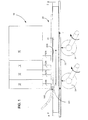
- Fig. 1 depicts a side view of a print station 10 having a plurality of print heads 12.
- Each print head 12 deposits ink, i.e., prints, on a face surface 14 of a substrate material 16 (e.g., such as a mailpiece envelope) as the substrate material 16 is conveyed through the print station 10.
- a substrate material 16 e.g., such as a mailpiece envelope
- mailpiece envelope 16 will, hereinafter, be used to mean any sheet and/or substrate material.
- Each of the print heads 12 includes one or more rows of print head nozzles 12N which deposit ink through an aperture/opening 18 in a registration device 20.
- the registration device 20 is disposed in combination with the print heads 12 and functions to maintain a prescribed separation distance between a face surface 16S of the mailpiece envelope 16 and each of the print head nozzles 12N.
- the separation distance ensures the efficacy of print operations inasmuch as the deposited ink requires a certain stand-off distance, i.e., spacing from the exit of the nozzles 12N to the face surface 14, to be deposited at a precise location on the face surface 16S of the mailpiece envelope 16.
- the mailpiece envelope 16 is conveyed through the print station 10 by a conventional transport system such as a conveyor belt 22 which may be supported on, or by, a series of spring-biased rollers 24.
- the spring-biased rollers 24 urge the conveyor belt 22, and consequently, mailpiece envelope 16, upwardly toward a registration surface 20S of the registration device 20.
- the separation distance between the print head nozzles 12N and the top face surface 20S of the mailpiece envelope may be accurately controlled. As a consequence, print quality is accurately maintained for optimum print performance.
- the registration surface 20S opposes and engages the face surface 16S (see Fig. 1 ) of the envelope 16 as the conveyor belt 22 transports the envelope 16 beneath the print head nozzles 12N of the print station 12.
- the registration surface 20S is textured to contact the face surface 16S of the mailpiece envelope 16 at multiple points, or regions, along the face surface 16S.
- the registration surface 20S defines a plurality of contact surfaces 30 which are substantially evenly distributed across the registration surface 20S and a plurality of non-contact regions 32 disposed therebetween.
- the contact surfaces 30 are (i) raised, (ii) have a substantially convex or arcuate contour, and, (iii) are operative to effect bridging of the mailpiece envelope 16, i.e., across the non-contact regions 32, such that registration surface 20S does not frictionally engage the face surface 16S of the mailpiece envelope at these regions 32.
- the textured surface i.e., which includes the contact surfaces 30 and non-contact regions 32, reduces the surface area in contact with the face surface 16S of the mailpiece envelope 16, i.e., as compared to the total surface area of a purely planar/flat registration surface employed in prior art registration devices. That is, the textured surface of the registration device 20 mitigates particulate matter removed/shed from the mailpiece envelope 16 by minimizing the friction and/or profile drag developed between the registration surface 20S of the registration device 20 and the face surface 16S of the mailpiece envelope 16.
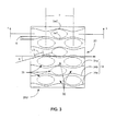
- the contact surfaces 30 may be produced by plurality of serpentine-shaped grooves 34 which extend in a direction substantially parallel to the feed path of the mailpiece envelope 16 (shown in the direction of arrow FP in Fig. 3 ).
- the grooves 34 may be aligned, i.e., in phase, or staggered, i.e., out-of-phase, relative to the feed path FP of the mailpiece envelope 16.
- Figs. 2 and 3 show the grooves in a staggered pattern such that the crest 34C of one groove 34a aligns a trough 34T of an adjacent groove 34b.
- each of the contact surfaces 30 define an elongate-diamond or elliptical shape (best seen in Fig. 3 ).
- serpentine-shaped grooves 34 having a pitch P (i.e., a distance or length between a pair of adjacent crests 34C or a pair of adjacent troughs 34T), of between about three-eights inches (3/8") to about one-quarter inches (1/4"), and a rise R (i.e., a distance or height from a minimum depth along one trough 34T to a maximum height along an adjacent crest 34C) of between about five thirty-seconds inches (5/34") to about seven thirty-seconds inches (7/34"), produces favorable results.
- a groove 34 having a substantially linear segment LS i.e., a segment shown in Fig.
- a textured registration surface 20S of the type described above may be fabricated from 304 polished stainless steel sheets having a 5-SM surface pattern available from RIMEX Metals Inc. located in the town of Edison, State of New Jersey.
- the surface texture of the registration device 20 has been discussed to mitigate particulate matter produced/removed/shed from the mailpiece envelope 16.
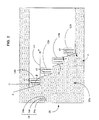
- Yet another characteristic of the registration device 20, which synergistically reduces the particulate matter relates to the shape of the opening 18, and, more particularly, to the shape or angle of the edges 40 upstream of each of the print head nozzles 12N. Referring back to Fig. 2 , the edges 40 define an obtuse angle ⁇ relative to the feed path FP of the mailpiece envelope 16 (i.e., the angle produced between line segments FP and FE).
- the obtuse angfe ⁇ is greater than about one-hundred and five degrees (105°) relative to the feed path of the substrate material. More preferably, the obtuse angle ⁇ is greater than about ninety-five degrees (95°) relative to the feed path of the substrate material.
- the registration surface 20S has been cut to produce an edge 40, i.e., along the lead angle ⁇ , wherein several of the contact surfaces 30 are severed at a point corresponding, or proximal, to the apex of a respective one of the contact surfaces 30. Additionally, the registration surface 20S has been cut such that the edge 40 is severed at a point corresponding to the non-contact areas 32, i.e., between adjacent contact surfaces 30.
- an edge 40 having fewer contact surfaces 30 and more non-contact regions 32 will shed/remove less particulate matter from the face surface 16S of the mailpiece envelope 16 than one with more contact surfaces and less non-contact regions 32.
- this configuration i.e., an edge which is cut along an incline, or at an obtuse angle relative to the feed path, ensures that the edge 40 will produce less particulate matter by reducing its tendency to whip or disturb the surface 16S of the mailpiece envelope 16.
- the present invention provides a registration device for a print station which mitigates the removal/production of particulate matter to optimize print station/inserter efficiency.
- the registration surface minimizes the disturbance of existing particulate matter by reducing the surface area contacting the surface of a substrate material/mailpiece envelope.
- an incline i.e., at an obtuse angle relative to the feed path, or off-axis relative to a line orthogonal to the feed path
- Increased efficiency is achieved by reducing the number purge cycles necessary to clear/clean the print head nozzles and the cost associated with lost productivity and ink consumption.
Landscapes
- Accessory Devices And Overall Control Thereof (AREA)
- Handling Of Sheets (AREA)
Abstract
Description
- The present invention relates to a registration device for use in a substrate print station and, more particularly, to a new and useful registration device for mitigating the production/removal of particulate matter, i.e., dust and debris, from the substrate material/mailpiece envelope as it engages a registration surface during print operations.
- Mailpiece creation systems such as mailpiece inserters are typically used by organizations such as banks, insurance companies, and utility companies to periodically produce a large volume of mailpieces, e.g., monthly billing or shareholders income/dividend statements. In many respects, mailpiece inserters are analogous to automated assembly equipment inasmuch as sheets, inserts and envelopes are conveyed along a feed path and assembled in or at various modules of the mailpiece inserter. That is, the various modules work cooperatively to process the sheets until a finished mailpiece is produced.
- A mailpiece inserter includes a variety of apparatus/modules for conveying and processing a substrate/sheet material along the feed path. Commonly mailpiece inserters include apparatus/modules for (i) feeding and singulating printed content material in a "feeder module", (ii) accumulating the content material to form a multi-sheet collation in an "accumulator", (iii) folding the content material to produce a variety of fold configurations such as a C-fold, Z-fold, bi-fold and gate fold, in a "folder", (iv) feeding mailpiece inserts such as coupons, brochures, and pamphlets, in combination with the content material, in a "chassis module" (v) inserting the folded/unfolded and/or nested content material into an envelope in an "envelope inserter", (vi) sealing the filled envelope in "sealing module" (vii) printing recipient/return addresses and/or postage indicia on the face of the mailpiece envelope at a "print station" and (viii) controlling the flow and speed of the content material at various locations along the feed path of the mailpiece inserter by a series of "buffer stations". In addition to these commonly employed apparatus/modules, mailpiece inserter may also include other modules for (i) binding/stitching an edge of sheet material to form a bound collation, i.e., via a stitcher/stapler module, and (ii) reversing the orientation of the substrate/sheet material, via a "sheet inverter" to print information on an opposite side of the sheet/content material.
- With respect to the printing station, it is common to register a face surface of each mailpiece with a registration plate such that an array of print heads may print information such as destination and return addresses on the face of each mailpiece. More specifically, the registration plate includes an aperture for accepting a stepped array of print head nozzles. The thickness of the registration plate provides a threshold "stand-off" dimension from the face surface of each mailpiece to each of the print head nozzles such that ink droplets may be precisely deposited.
- Furthermore, the array of print heads and registration plate are typically disposed over, and/or in opposed relation to, an underlying conveyance system such as one or more conveyor belts. Mailpieces are conveyed along the belt(s), move under the registration plate and passed by the print head nozzles as ink is deposited. To ensure that mailpieces slide smoothly beneath the registration plate, i.e., without jamming, the spacing between the underlying conveyance system, e.g., the conveyance belt (s), and the registration plate must be closely controlled. That is, with each mail run/print job performed by the print module, the necessary clearance gap must be established based upon the anticipated thickness of mailpieces being processed. Alternatively, the underlying conveyance system/belt may be compliant to allow envelopes of variable thickness dimension move under the registration plate while the deck the of conveyance system/belt is displaced by the geometric variation in envelope thickness.
- Furthermore, as a mailpiece passes the registration plate, particulate matter, which may have collected on an envelope during pre-processing, can be disturbed and become airborne due to engagement of the envelope with the registration plate. Additionally, the frictional engagement with the registration plate may produce additional dust and debris. As more particulate matter is disturbed/removed/produced, the print station must perform additional purge cycles to clear the print head nozzles of dust and debris. As a result, the mailpiece inserter is halted, or momentarily/temporarily discontinued, to allow the purge cycle to clear/clean the print head nozzles. While such purge cycles must be tolerated to permit smooth operation of the print station, the down time is unproductive and costly to the operator. Furthermore, inasmuch as the ink used to purge the print head nozzles is costly, it is desirable to minimize the number of purge cycles that a print station performs to minimize the cost of the ink consumed.
- A need, therefore, exists for a print station which mitigates the removal/production of particulate matter to optimize print station/inserter efficiency. Such increased efficiency may be achieved by reducing the number purge cycles necessary to clear/clean the print head nozzles and the cost associated with lost productivity and ink consumption.
- A registration device is provided for use in combination with an array of print head nozzles operative to deposit ink on a substrate material. The registration device is operative to maintain a prescribed separation distance between an array of print head nozzles and a substrate material during print operations and includes a registration surface which opposes a face surface of the substrate material and is textured to define a plurality of contact points. The contact points are substantially evenly distributed over, and engage, the face surface of the substrate material, to reduce the total surface area in contact with the substrate material and the particulate matter which may be shed from, and/or produced by frictional engagement with, the substrate material.
- The accompanying drawings illustrate presently preferred embodiments of the invention and, together with the general description given above and the detailed description given below serve to explain the principles of the invention. As shown throughout the drawings, like reference numerals designate like or corresponding parts.
-
Figure 1 is a side view of a registration device and print station according to the present invention wherein an array of print heads is disposed in combination with the registration device to deposit ink on a face surface of a mailpiece envelope. -
Figure 2 is a view taken substantially along line 2 - 2 ofFig. 1 depicting a textured surface of the registration device which includes a plurality of raised contact surfaces and at least one upstream edge which is inclined relative to a line orthogonal to the feed path of the mailpiece envelope. -
Figure 3 is an enlarged view of the textured registration surface within a region 3 ofFig. 2 , wherein the contact surfaces are defined by a plurality of serpentine-shaped surface grooves which are out-of-phase to stagger the arrangement of contact surfaces. -
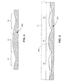
Figure 4 is an enlarged cross sectional view taken substantially along line 4 - 4 ofFig. 3 depicting a convex or arcuate surface of each contact surface. -
Figure 5 is an enlarged cross sectional view taken substantially along line 5 - 5 ofFig. 3 depicting an upstream edge to emphasize the effect of severing/cutting the textured surface of the registration device along an edge which is off-axis relative to a line orthogonal to the feed path of the mailpiece envelope. - A registration device and print station are described for printing information on a mailpiece envelope such as a destination address, return address and postage indicia for delivery of the mailpiece. While the invention is described in the context of a mailpiece inserter, the registration device and print station described herein are applicable to any printer wherein a substrate material is registered against a registration device for maintaining a prescribed separation distance between an array of print head nozzles and a substrate material during print operations. Consequently, the detailed description and illustrations are merely indicative of an embodiment of the invention, and, accordingly, the invention should be broadly interpreted in accordance with the appended claims.
-
Fig. 1 depicts a side view of aprint station 10 having a plurality ofprint heads 12. Each print head 12 deposits ink, i.e., prints, on a face surface 14 of a substrate material 16 (e.g., such as a mailpiece envelope) as thesubstrate material 16 is conveyed through theprint station 10. Inasmuch as the invention is principally described in the context of aprint station 12 for a mailpiece inserter, theterm mailpiece envelope 16 will, hereinafter, be used to mean any sheet and/or substrate material. Each of theprint heads 12 includes one or more rows ofprint head nozzles 12N which deposit ink through an aperture/opening 18 in aregistration device 20. - The
registration device 20 is disposed in combination with theprint heads 12 and functions to maintain a prescribed separation distance between aface surface 16S of themailpiece envelope 16 and each of theprint head nozzles 12N. The separation distance ensures the efficacy of print operations inasmuch as the deposited ink requires a certain stand-off distance, i.e., spacing from the exit of thenozzles 12N to the face surface 14, to be deposited at a precise location on theface surface 16S of themailpiece envelope 16. - The
mailpiece envelope 16 is conveyed through theprint station 10 by a conventional transport system such as aconveyor belt 22 which may be supported on, or by, a series of spring-biased rollers 24. The spring-biased rollers 24 urge theconveyor belt 22, and consequently,mailpiece envelope 16, upwardly toward aregistration surface 20S of theregistration device 20. By urging theenvelope 16 upwardly against theregistration surface 20S, the separation distance between theprint head nozzles 12N and thetop face surface 20S of the mailpiece envelope may be accurately controlled. As a consequence, print quality is accurately maintained for optimum print performance. - In
Figs. 1 through 4 , theregistration surface 20S opposes and engages theface surface 16S (seeFig. 1 ) of theenvelope 16 as theconveyor belt 22 transports theenvelope 16 beneath theprint head nozzles 12N of theprint station 12. Theregistration surface 20S is textured to contact theface surface 16S of themailpiece envelope 16 at multiple points, or regions, along theface surface 16S. Theregistration surface 20S defines a plurality ofcontact surfaces 30 which are substantially evenly distributed across theregistration surface 20S and a plurality ofnon-contact regions 32 disposed therebetween. Thecontact surfaces 30 are (i) raised, (ii) have a substantially convex or arcuate contour, and, (iii) are operative to effect bridging of themailpiece envelope 16, i.e., across thenon-contact regions 32, such thatregistration surface 20S does not frictionally engage theface surface 16S of the mailpiece envelope at theseregions 32. - As will be discussed in greater detail hereinafter, the textured surface, i.e., which includes the
contact surfaces 30 andnon-contact regions 32, reduces the surface area in contact with theface surface 16S of themailpiece envelope 16, i.e., as compared to the total surface area of a purely planar/flat registration surface employed in prior art registration devices. That is, the textured surface of theregistration device 20 mitigates particulate matter removed/shed from themailpiece envelope 16 by minimizing the friction and/or profile drag developed between theregistration surface 20S of theregistration device 20 and theface surface 16S of themailpiece envelope 16. - The
contact surfaces 30 may be produced by plurality of serpentine-shaped grooves 34 which extend in a direction substantially parallel to the feed path of the mailpiece envelope 16 (shown in the direction of arrow FP inFig. 3 ). Thegrooves 34 may be aligned, i.e., in phase, or staggered, i.e., out-of-phase, relative to the feed path FP of themailpiece envelope 16.Figs. 2 and3 show the grooves in a staggered pattern such that thecrest 34C of onegroove 34a aligns atrough 34T of anadjacent groove 34b. Furthermore, by aligninggrooves 34 in an out-of-phase arrangement, thecontact surfaces 30 are staggered from one, or a first, row oftandem contact surfaces 30 to an adjacent, or second, row oftandem contact surfaces 30. Moreover, as a consequence of the shape and alignment of thegrooves 34, each of thecontact surfaces 30 define an elongate-diamond or elliptical shape (best seen inFig. 3 ). - Upon examination of various patterns, shapes and sizes, it has been determined that serpentine-
shaped grooves 34 having a pitch P (i.e., a distance or length between a pair ofadjacent crests 34C or a pair ofadjacent troughs 34T), of between about three-eights inches (3/8") to about one-quarter inches (1/4"), and a rise R (i.e., a distance or height from a minimum depth along onetrough 34T to a maximum height along anadjacent crest 34C) of between about five thirty-seconds inches (5/34") to about seven thirty-seconds inches (7/34"), produces favorable results. Moreover, agroove 34 having a substantially linear segment LS (i.e., a segment shown inFig. 3 connecting curvilinear segments at the apex of onecrest 34C and the base of anadjacent trough 34T) such as the serpentine groove shown in the described embodiment, defines a lead angle θ which is between about five degrees (5°) to about fifteen degrees (15°) yields favorable results. In the described embodiment, atextured registration surface 20S of the type described above may be fabricated from 304 polished stainless steel sheets having a 5-SM surface pattern available from RIMEX Metals Inc. located in the town of Edison, State of New Jersey. - Thus far in our discussion, the surface texture of the
registration device 20 has been discussed to mitigate particulate matter produced/removed/shed from themailpiece envelope 16. Yet another characteristic of theregistration device 20, which synergistically reduces the particulate matter, relates to the shape of the opening 18, and, more particularly, to the shape or angle of theedges 40 upstream of each of theprint head nozzles 12N. Referring back toFig. 2 , theedges 40 define an obtuse angle β relative to the feed path FP of the mailpiece envelope 16 (i.e., the angle produced between line segments FP and FE). More particularly, in the described embodiment, the obtuse angfe β is greater than about one-hundred and five degrees (105°) relative to the feed path of the substrate material. More preferably, the obtuse angle β is greater than about ninety-five degrees (95°) relative to the feed path of the substrate material. - The significance of producing/ cutting the
upstream edges 40 along an incline will be appreciated by examiningFig. 5 . Therein, theregistration surface 20S has been cut to produce anedge 40, i.e., along the lead angle β, wherein several of the contact surfaces 30 are severed at a point corresponding, or proximal, to the apex of a respective one of the contact surfaces 30. Additionally, theregistration surface 20S has been cut such that theedge 40 is severed at a point corresponding to thenon-contact areas 32, i.e., between adjacent contact surfaces 30. - Inasmuch a discontinuous edge, or portion, of the
registration device 20 has a tendency to whip, or disturb, thesurface 16S of amailpiece envelope 16 more thoroughly, than a continuous surface, anedge 40 having fewer contact surfaces 30 and morenon-contact regions 32 will shed/remove less particulate matter from theface surface 16S of themailpiece envelope 16 than one with more contact surfaces and lessnon-contact regions 32. By cutting theupstream edge 40 at an angle relative to a line FO orthogonal to the feed path, theedge 40 will be severed at several locations along thesurface 20, however, at least one location will correspond to at least onenon-contact region 32 of thesurface 20S. Consequently, this configuration, i.e., an edge which is cut along an incline, or at an obtuse angle relative to the feed path, ensures that theedge 40 will produce less particulate matter by reducing its tendency to whip or disturb thesurface 16S of themailpiece envelope 16. - In summary, the present invention provides a registration device for a print station which mitigates the removal/production of particulate matter to optimize print station/inserter efficiency. The registration surface minimizes the disturbance of existing particulate matter by reducing the surface area contacting the surface of a substrate material/mailpiece envelope. By cutting an opening, through which ink is deposited, along an incline (i.e., at an obtuse angle relative to the feed path, or off-axis relative to a line orthogonal to the feed path) the tendency of the edge to disturb or remove particulate mater is also reduced. Increased efficiency is achieved by reducing the number purge cycles necessary to clear/clean the print head nozzles and the cost associated with lost productivity and ink consumption.
- It is to be understood that all of the present figures, and the accompanying narrative discussions of preferred embodiments, do not purport to be completely rigorous treatments of the methods and systems under consideration. For example, while the invention describes an interval of time for completing a phase of sorting operations, it should be appreciated that the processing time may differ. A person skilled in the art will understand that the steps of the present application represent general cause-and-effect relationships that do not exclude intermediate interactions of various types, and will further understand that the various structures and mechanisms described in this application can be implemented by a variety of different combinations of hardware and software, methods of escorting and storing individual mailpieces and in various configurations which need not be further elaborated herein.
Claims (10)
- A print station for a mailpiece inserter comprising:an array of print head nozzles operative to deposit ink on a mailpiece envelope being conveyed along a feed path; anda registration plate spatially positioned relative to the print head nozzles and operative to maintain a prescribed separation distance between the registration plate and the print head nozzles, the registration plate having a registration surface opposing a top face surface of the mailpiece envelope and being textured to define a plurality of contact surfaces substantially evenly-distributed over, and engaging, the face surface of the substrate material, the contact points reducing a surface area in contact with the substrate material to mitigate particulate matter shed from the substrate material.
- The print station according to claim 1 wherein the contact surfaces have a substantially arcuate shaped surface contour.
- The print station according to claim 1 or claim 2 wherein the contact surfaces have a substantially elongate diamond shape.
- The print station according to any preceding claim, wherein the contact surfaces are defined by a plurality of grooves oriented substantially parallel to a feed path of the mailpiece envelope.
- The print station according to claim 4 wherein each of the grooves defines a substantially serpentine-shape.
- The print station according to claim 4 or claim 5 wherein adjacent grooves are out-of-phase and the contact surfaces are staggered from one row of contact surfaces to an adjacent row of contact surfaces.
- The print station according to any of claims 4 to 6 wherein each groove defines a lead angle within a range of between about five degrees (5°) to about fifteen degrees (15°).
- The print station according to any preceding claim wherein the registration surface includes an opening through which ink is deposited, the opening having a trailing edge upstream of at least one of the nozzles and wherein the trailing edge defines an obtuse angle relative to the feed path of the mailpiece envelope.
- The print station according to claim 8 wherein the obtuse angle is greater than about one-hundred and five degrees (105°) relative to the feed path of the mailpiece envelope.
- The print station according to claim 8 wherein the obtuse angle is greater than about ninety-five degrees (95°) relative to the feed path of the mailpiece envelope.
Applications Claiming Priority (1)
| Application Number | Priority Date | Filing Date | Title |
|---|---|---|---|
| US12/791,487 US8328328B2 (en) | 2010-06-01 | 2010-06-01 | Device for mitigating the production/removal of particulate matter from a substrate/mailpiece envelope |
Publications (3)
| Publication Number | Publication Date |
|---|---|
| EP2392464A2 true EP2392464A2 (en) | 2011-12-07 |
| EP2392464A3 EP2392464A3 (en) | 2012-08-29 |
| EP2392464B1 EP2392464B1 (en) | 2013-05-29 |
Family
ID=44461924
Family Applications (1)
| Application Number | Title | Priority Date | Filing Date |
|---|---|---|---|
| EP11168413.0A Revoked EP2392464B1 (en) | 2010-06-01 | 2011-06-01 | Registration device for mitigating the production/removal of particulate matter from a substrate/mailpiece envelope |
Country Status (2)
| Country | Link |
|---|---|
| US (1) | US8328328B2 (en) |
| EP (1) | EP2392464B1 (en) |
Family Cites Families (6)
| Publication number | Priority date | Publication date | Assignee | Title |
|---|---|---|---|---|
| US4821049A (en) | 1987-12-02 | 1989-04-11 | Pitney Bowes Inc. | Substrate transport apparatus, especially for mail handling |
| JP3841315B2 (en) | 1995-12-26 | 2006-11-01 | キヤノン株式会社 | Printing apparatus and printing method used in the apparatus |
| US5913627A (en) | 1997-12-11 | 1999-06-22 | Pitney Bowes Inc. | Guide and support structure for a mailing machine |
| US20080218547A1 (en) * | 2007-03-06 | 2008-09-11 | Canon Kabushiki Kaisha | Ink jet printing apparatus and ink jet printing method |
| US8235491B2 (en) | 2009-03-02 | 2012-08-07 | Pitney Bowes Inc. | Registration plate assembly for mailpiece conveyance system |
| US8506051B2 (en) * | 2009-12-28 | 2013-08-13 | Xerox Corporation | Process for preparing an ink jet print head front face having a textured superoleophobic surface |
-
2010
- 2010-06-01 US US12/791,487 patent/US8328328B2/en not_active Expired - Fee Related
-
2011
- 2011-06-01 EP EP11168413.0A patent/EP2392464B1/en not_active Revoked
Non-Patent Citations (1)
| Title |
|---|
| None |
Also Published As
| Publication number | Publication date |
|---|---|
| EP2392464B1 (en) | 2013-05-29 |
| US20110292119A1 (en) | 2011-12-01 |
| US8328328B2 (en) | 2012-12-11 |
| EP2392464A3 (en) | 2012-08-29 |
Similar Documents
| Publication | Publication Date | Title |
|---|---|---|
| US7600755B1 (en) | System and method for preventing envelope distortion in a mailpiece fabrication system | |
| CA2292066C (en) | High speed pneumatic document input system | |
| US20100328399A1 (en) | Print module having pivotable support/instrumentation rack for print head assembly | |
| EP2886472B1 (en) | System and method for ensuring cutting accuracy in a mailpiece wrapper | |
| JP2012501880A (en) | Envelope transport positioning apparatus and related methods | |
| EP2226199A1 (en) | Mailpiece conveyance system | |
| WO2007085101A1 (en) | Apparatus for collating flat objects and for conveying the collated objects further | |
| EP2392464B1 (en) | Registration device for mitigating the production/removal of particulate matter from a substrate/mailpiece envelope | |
| AU2009288642B2 (en) | Inserting apparatus for discrete objects into envelopes and related methods | |
| US7857122B2 (en) | Flexible vacuum conveyance/manifold system | |
| US8235491B2 (en) | Registration plate assembly for mailpiece conveyance system | |
| US5975519A (en) | Separator stone adjustment assembly | |
| US8215629B2 (en) | System and method for producing and arranging sheet material for use in a mailpiece inserter | |
| CA2548718C (en) | Cut sheet feeder | |
| EP2716470B1 (en) | Method and system for identifying/outsorting improperly wrapped envelopes in a mailpiece fabrication system | |
| US20090083198A1 (en) | Process for franking, printing, and/or producing images on flat mail items | |
| US20100078873A1 (en) | Singulating sheet feeder | |
| AU2009288645B2 (en) | Transporting apparatus for web products and related methods | |
| US8096932B2 (en) | System and method for processing nested/unnested mailpiece content material | |
| US7600747B2 (en) | Platen for cut sheet feeder | |
| US20100059919A1 (en) | Transporting apparatus for discrete sheets into envelopes and related methods | |
| US8327993B2 (en) | Safety device for a linear actuation system | |
| EP1803667B1 (en) | Apparatus and method for separating flat items from stacks | |
| JP2026023725A (en) | Automatic collating apparatus | |
| US20080211175A1 (en) | Method and apparatus for feeding multi-sheet documents |
Legal Events
| Date | Code | Title | Description |
|---|---|---|---|
| AK | Designated contracting states |
Kind code of ref document: A2 Designated state(s): AL AT BE BG CH CY CZ DE DK EE ES FI FR GB GR HR HU IE IS IT LI LT LU LV MC MK MT NL NO PL PT RO RS SE SI SK SM TR |
|
| AX | Request for extension of the european patent |
Extension state: BA ME |
|
| PUAI | Public reference made under article 153(3) epc to a published international application that has entered the european phase |
Free format text: ORIGINAL CODE: 0009012 |
|
| PUAL | Search report despatched |
Free format text: ORIGINAL CODE: 0009013 |
|
| AK | Designated contracting states |
Kind code of ref document: A3 Designated state(s): AL AT BE BG CH CY CZ DE DK EE ES FI FR GB GR HR HU IE IS IT LI LT LU LV MC MK MT NL NO PL PT RO RS SE SI SK SM TR |
|
| AX | Request for extension of the european patent |
Extension state: BA ME |
|
| RIC1 | Information provided on ipc code assigned before grant |
Ipc: B41J 13/12 20060101ALI20120720BHEP Ipc: B41J 11/00 20060101AFI20120720BHEP |
|
| 17P | Request for examination filed |
Effective date: 20121024 |
|
| GRAP | Despatch of communication of intention to grant a patent |
Free format text: ORIGINAL CODE: EPIDOSNIGR1 |
|
| GRAS | Grant fee paid |
Free format text: ORIGINAL CODE: EPIDOSNIGR3 |
|
| GRAA | (expected) grant |
Free format text: ORIGINAL CODE: 0009210 |
|
| AK | Designated contracting states |
Kind code of ref document: B1 Designated state(s): AL AT BE BG CH CY CZ DE DK EE ES FI FR GB GR HR HU IE IS IT LI LT LU LV MC MK MT NL NO PL PT RO RS SE SI SK SM TR |
|
| REG | Reference to a national code |
Ref country code: GB Ref legal event code: FG4D |
|
| REG | Reference to a national code |
Ref country code: CH Ref legal event code: EP |
|
| REG | Reference to a national code |
Ref country code: AT Ref legal event code: REF Ref document number: 614113 Country of ref document: AT Kind code of ref document: T Effective date: 20130615 |
|
| REG | Reference to a national code |
Ref country code: IE Ref legal event code: FG4D |
|
| REG | Reference to a national code |
Ref country code: DE Ref legal event code: R096 Ref document number: 602011001785 Country of ref document: DE Effective date: 20130801 |
|
| REG | Reference to a national code |
Ref country code: AT Ref legal event code: MK05 Ref document number: 614113 Country of ref document: AT Kind code of ref document: T Effective date: 20130529 |
|
| REG | Reference to a national code |
Ref country code: LT Ref legal event code: MG4D |
|
| PG25 | Lapsed in a contracting state [announced via postgrant information from national office to epo] |
Ref country code: LT Free format text: LAPSE BECAUSE OF FAILURE TO SUBMIT A TRANSLATION OF THE DESCRIPTION OR TO PAY THE FEE WITHIN THE PRESCRIBED TIME-LIMIT Effective date: 20130529 Ref country code: IS Free format text: LAPSE BECAUSE OF FAILURE TO SUBMIT A TRANSLATION OF THE DESCRIPTION OR TO PAY THE FEE WITHIN THE PRESCRIBED TIME-LIMIT Effective date: 20130929 Ref country code: GR Free format text: LAPSE BECAUSE OF FAILURE TO SUBMIT A TRANSLATION OF THE DESCRIPTION OR TO PAY THE FEE WITHIN THE PRESCRIBED TIME-LIMIT Effective date: 20130830 Ref country code: AT Free format text: LAPSE BECAUSE OF FAILURE TO SUBMIT A TRANSLATION OF THE DESCRIPTION OR TO PAY THE FEE WITHIN THE PRESCRIBED TIME-LIMIT Effective date: 20130529 Ref country code: SI Free format text: LAPSE BECAUSE OF FAILURE TO SUBMIT A TRANSLATION OF THE DESCRIPTION OR TO PAY THE FEE WITHIN THE PRESCRIBED TIME-LIMIT Effective date: 20130529 Ref country code: ES Free format text: LAPSE BECAUSE OF FAILURE TO SUBMIT A TRANSLATION OF THE DESCRIPTION OR TO PAY THE FEE WITHIN THE PRESCRIBED TIME-LIMIT Effective date: 20130909 Ref country code: FI Free format text: LAPSE BECAUSE OF FAILURE TO SUBMIT A TRANSLATION OF THE DESCRIPTION OR TO PAY THE FEE WITHIN THE PRESCRIBED TIME-LIMIT Effective date: 20130529 Ref country code: NO Free format text: LAPSE BECAUSE OF FAILURE TO SUBMIT A TRANSLATION OF THE DESCRIPTION OR TO PAY THE FEE WITHIN THE PRESCRIBED TIME-LIMIT Effective date: 20130829 Ref country code: SE Free format text: LAPSE BECAUSE OF FAILURE TO SUBMIT A TRANSLATION OF THE DESCRIPTION OR TO PAY THE FEE WITHIN THE PRESCRIBED TIME-LIMIT Effective date: 20130529 Ref country code: PT Free format text: LAPSE BECAUSE OF FAILURE TO SUBMIT A TRANSLATION OF THE DESCRIPTION OR TO PAY THE FEE WITHIN THE PRESCRIBED TIME-LIMIT Effective date: 20130930 |
|
| REG | Reference to a national code |
Ref country code: NL Ref legal event code: VDEP Effective date: 20130529 |
|
| PG25 | Lapsed in a contracting state [announced via postgrant information from national office to epo] |
Ref country code: HR Free format text: LAPSE BECAUSE OF FAILURE TO SUBMIT A TRANSLATION OF THE DESCRIPTION OR TO PAY THE FEE WITHIN THE PRESCRIBED TIME-LIMIT Effective date: 20130529 Ref country code: RS Free format text: LAPSE BECAUSE OF FAILURE TO SUBMIT A TRANSLATION OF THE DESCRIPTION OR TO PAY THE FEE WITHIN THE PRESCRIBED TIME-LIMIT Effective date: 20130529 Ref country code: BG Free format text: LAPSE BECAUSE OF FAILURE TO SUBMIT A TRANSLATION OF THE DESCRIPTION OR TO PAY THE FEE WITHIN THE PRESCRIBED TIME-LIMIT Effective date: 20130829 Ref country code: PL Free format text: LAPSE BECAUSE OF FAILURE TO SUBMIT A TRANSLATION OF THE DESCRIPTION OR TO PAY THE FEE WITHIN THE PRESCRIBED TIME-LIMIT Effective date: 20130529 |
|
| PG25 | Lapsed in a contracting state [announced via postgrant information from national office to epo] |
Ref country code: LV Free format text: LAPSE BECAUSE OF FAILURE TO SUBMIT A TRANSLATION OF THE DESCRIPTION OR TO PAY THE FEE WITHIN THE PRESCRIBED TIME-LIMIT Effective date: 20130529 |
|
| PG25 | Lapsed in a contracting state [announced via postgrant information from national office to epo] |
Ref country code: CZ Free format text: LAPSE BECAUSE OF FAILURE TO SUBMIT A TRANSLATION OF THE DESCRIPTION OR TO PAY THE FEE WITHIN THE PRESCRIBED TIME-LIMIT Effective date: 20130529 Ref country code: EE Free format text: LAPSE BECAUSE OF FAILURE TO SUBMIT A TRANSLATION OF THE DESCRIPTION OR TO PAY THE FEE WITHIN THE PRESCRIBED TIME-LIMIT Effective date: 20130529 Ref country code: DK Free format text: LAPSE BECAUSE OF FAILURE TO SUBMIT A TRANSLATION OF THE DESCRIPTION OR TO PAY THE FEE WITHIN THE PRESCRIBED TIME-LIMIT Effective date: 20130529 Ref country code: SK Free format text: LAPSE BECAUSE OF FAILURE TO SUBMIT A TRANSLATION OF THE DESCRIPTION OR TO PAY THE FEE WITHIN THE PRESCRIBED TIME-LIMIT Effective date: 20130529 Ref country code: BE Free format text: LAPSE BECAUSE OF FAILURE TO SUBMIT A TRANSLATION OF THE DESCRIPTION OR TO PAY THE FEE WITHIN THE PRESCRIBED TIME-LIMIT Effective date: 20130529 |
|
| PG25 | Lapsed in a contracting state [announced via postgrant information from national office to epo] |
Ref country code: NL Free format text: LAPSE BECAUSE OF FAILURE TO SUBMIT A TRANSLATION OF THE DESCRIPTION OR TO PAY THE FEE WITHIN THE PRESCRIBED TIME-LIMIT Effective date: 20130529 Ref country code: RO Free format text: LAPSE BECAUSE OF FAILURE TO SUBMIT A TRANSLATION OF THE DESCRIPTION OR TO PAY THE FEE WITHIN THE PRESCRIBED TIME-LIMIT Effective date: 20130529 Ref country code: IT Free format text: LAPSE BECAUSE OF FAILURE TO SUBMIT A TRANSLATION OF THE DESCRIPTION OR TO PAY THE FEE WITHIN THE PRESCRIBED TIME-LIMIT Effective date: 20130529 Ref country code: MC Free format text: LAPSE BECAUSE OF FAILURE TO SUBMIT A TRANSLATION OF THE DESCRIPTION OR TO PAY THE FEE WITHIN THE PRESCRIBED TIME-LIMIT Effective date: 20130529 |
|
| PLBI | Opposition filed |
Free format text: ORIGINAL CODE: 0009260 |
|
| REG | Reference to a national code |
Ref country code: IE Ref legal event code: MM4A |
|
| 26 | Opposition filed |
Opponent name: FRANCOTYP-POSTALIA GMBH Effective date: 20140124 |
|
| PLAX | Notice of opposition and request to file observation + time limit sent |
Free format text: ORIGINAL CODE: EPIDOSNOBS2 |
|
| PG25 | Lapsed in a contracting state [announced via postgrant information from national office to epo] |
Ref country code: IE Free format text: LAPSE BECAUSE OF NON-PAYMENT OF DUE FEES Effective date: 20130601 |
|
| REG | Reference to a national code |
Ref country code: DE Ref legal event code: R026 Ref document number: 602011001785 Country of ref document: DE Effective date: 20140124 |
|
| PLBB | Reply of patent proprietor to notice(s) of opposition received |
Free format text: ORIGINAL CODE: EPIDOSNOBS3 |
|
| REG | Reference to a national code |
Ref country code: CH Ref legal event code: PL |
|
| PLAB | Opposition data, opponent's data or that of the opponent's representative modified |
Free format text: ORIGINAL CODE: 0009299OPPO |
|
| PG25 | Lapsed in a contracting state [announced via postgrant information from national office to epo] |
Ref country code: MT Free format text: LAPSE BECAUSE OF FAILURE TO SUBMIT A TRANSLATION OF THE DESCRIPTION OR TO PAY THE FEE WITHIN THE PRESCRIBED TIME-LIMIT Effective date: 20130529 |
|
| R26 | Opposition filed (corrected) |
Opponent name: FRANCOTYP-POSTALIA GMBH Effective date: 20140124 |
|
| PG25 | Lapsed in a contracting state [announced via postgrant information from national office to epo] |
Ref country code: CH Free format text: LAPSE BECAUSE OF NON-PAYMENT OF DUE FEES Effective date: 20140630 Ref country code: LI Free format text: LAPSE BECAUSE OF NON-PAYMENT OF DUE FEES Effective date: 20140630 |
|
| PG25 | Lapsed in a contracting state [announced via postgrant information from national office to epo] |
Ref country code: SM Free format text: LAPSE BECAUSE OF FAILURE TO SUBMIT A TRANSLATION OF THE DESCRIPTION OR TO PAY THE FEE WITHIN THE PRESCRIBED TIME-LIMIT Effective date: 20130529 |
|
| REG | Reference to a national code |
Ref country code: FR Ref legal event code: PLFP Year of fee payment: 5 |
|
| PG25 | Lapsed in a contracting state [announced via postgrant information from national office to epo] |
Ref country code: CY Free format text: LAPSE BECAUSE OF FAILURE TO SUBMIT A TRANSLATION OF THE DESCRIPTION OR TO PAY THE FEE WITHIN THE PRESCRIBED TIME-LIMIT Effective date: 20130529 Ref country code: TR Free format text: LAPSE BECAUSE OF FAILURE TO SUBMIT A TRANSLATION OF THE DESCRIPTION OR TO PAY THE FEE WITHIN THE PRESCRIBED TIME-LIMIT Effective date: 20130529 |
|
| PG25 | Lapsed in a contracting state [announced via postgrant information from national office to epo] |
Ref country code: MK Free format text: LAPSE BECAUSE OF FAILURE TO SUBMIT A TRANSLATION OF THE DESCRIPTION OR TO PAY THE FEE WITHIN THE PRESCRIBED TIME-LIMIT Effective date: 20130529 Ref country code: LU Free format text: LAPSE BECAUSE OF NON-PAYMENT OF DUE FEES Effective date: 20130601 Ref country code: HU Free format text: LAPSE BECAUSE OF FAILURE TO SUBMIT A TRANSLATION OF THE DESCRIPTION OR TO PAY THE FEE WITHIN THE PRESCRIBED TIME-LIMIT; INVALID AB INITIO Effective date: 20110601 |
|
| PGFP | Annual fee paid to national office [announced via postgrant information from national office to epo] |
Ref country code: GB Payment date: 20150629 Year of fee payment: 5 Ref country code: DE Payment date: 20150629 Year of fee payment: 5 |
|
| PGFP | Annual fee paid to national office [announced via postgrant information from national office to epo] |
Ref country code: FR Payment date: 20150617 Year of fee payment: 5 |
|
| RDAF | Communication despatched that patent is revoked |
Free format text: ORIGINAL CODE: EPIDOSNREV1 |
|
| REG | Reference to a national code |
Ref country code: DE Ref legal event code: R103 Ref document number: 602011001785 Country of ref document: DE Ref country code: DE Ref legal event code: R064 Ref document number: 602011001785 Country of ref document: DE |
|
| RDAG | Patent revoked |
Free format text: ORIGINAL CODE: 0009271 |
|
| STAA | Information on the status of an ep patent application or granted ep patent |
Free format text: STATUS: PATENT REVOKED |
|
| 27W | Patent revoked |
Effective date: 20151204 |
|
| GBPR | Gb: patent revoked under art. 102 of the ep convention designating the uk as contracting state |
Effective date: 20151204 |
|
| PG25 | Lapsed in a contracting state [announced via postgrant information from national office to epo] |
Ref country code: AL Free format text: LAPSE BECAUSE OF FAILURE TO SUBMIT A TRANSLATION OF THE DESCRIPTION OR TO PAY THE FEE WITHIN THE PRESCRIBED TIME-LIMIT Effective date: 20130529 |