EP2392297A1 - Bodily fluid treating article and wearing article including same - Google Patents
Bodily fluid treating article and wearing article including same Download PDFInfo
- Publication number
- EP2392297A1 EP2392297A1 EP09839139A EP09839139A EP2392297A1 EP 2392297 A1 EP2392297 A1 EP 2392297A1 EP 09839139 A EP09839139 A EP 09839139A EP 09839139 A EP09839139 A EP 09839139A EP 2392297 A1 EP2392297 A1 EP 2392297A1
- Authority
- EP
- European Patent Office
- Prior art keywords
- bodily fluid
- article
- container
- opening
- fluid treating
- Prior art date
- Legal status (The legal status is an assumption and is not a legal conclusion. Google has not performed a legal analysis and makes no representation as to the accuracy of the status listed.)
- Withdrawn
Links
Images




Classifications
-
- A—HUMAN NECESSITIES
- A61—MEDICAL OR VETERINARY SCIENCE; HYGIENE
- A61F—FILTERS IMPLANTABLE INTO BLOOD VESSELS; PROSTHESES; DEVICES PROVIDING PATENCY TO, OR PREVENTING COLLAPSING OF, TUBULAR STRUCTURES OF THE BODY, e.g. STENTS; ORTHOPAEDIC, NURSING OR CONTRACEPTIVE DEVICES; FOMENTATION; TREATMENT OR PROTECTION OF EYES OR EARS; BANDAGES, DRESSINGS OR ABSORBENT PADS; FIRST-AID KITS
- A61F5/00—Orthopaedic methods or devices for non-surgical treatment of bones or joints; Nursing devices ; Anti-rape devices
- A61F5/44—Devices worn by the patient for reception of urine, faeces, catamenial or other discharge; Colostomy devices
- A61F5/451—Genital or anal receptacles
-
- A—HUMAN NECESSITIES
- A61—MEDICAL OR VETERINARY SCIENCE; HYGIENE
- A61F—FILTERS IMPLANTABLE INTO BLOOD VESSELS; PROSTHESES; DEVICES PROVIDING PATENCY TO, OR PREVENTING COLLAPSING OF, TUBULAR STRUCTURES OF THE BODY, e.g. STENTS; ORTHOPAEDIC, NURSING OR CONTRACEPTIVE DEVICES; FOMENTATION; TREATMENT OR PROTECTION OF EYES OR EARS; BANDAGES, DRESSINGS OR ABSORBENT PADS; FIRST-AID KITS
- A61F13/00—Bandages or dressings; Absorbent pads
- A61F13/15—Absorbent pads, e.g. sanitary towels, swabs or tampons for external or internal application to the body; Supporting or fastening means therefor; Tampon applicators
- A61F13/45—Absorbent pads, e.g. sanitary towels, swabs or tampons for external or internal application to the body; Supporting or fastening means therefor; Tampon applicators characterised by the shape
- A61F13/49—Absorbent pads, e.g. sanitary towels, swabs or tampons for external or internal application to the body; Supporting or fastening means therefor; Tampon applicators characterised by the shape specially adapted to be worn around the waist, e.g. diapers or nappies
-
- A—HUMAN NECESSITIES
- A61—MEDICAL OR VETERINARY SCIENCE; HYGIENE
- A61F—FILTERS IMPLANTABLE INTO BLOOD VESSELS; PROSTHESES; DEVICES PROVIDING PATENCY TO, OR PREVENTING COLLAPSING OF, TUBULAR STRUCTURES OF THE BODY, e.g. STENTS; ORTHOPAEDIC, NURSING OR CONTRACEPTIVE DEVICES; FOMENTATION; TREATMENT OR PROTECTION OF EYES OR EARS; BANDAGES, DRESSINGS OR ABSORBENT PADS; FIRST-AID KITS
- A61F13/00—Bandages or dressings; Absorbent pads
- A61F13/15—Absorbent pads, e.g. sanitary towels, swabs or tampons for external or internal application to the body; Supporting or fastening means therefor; Tampon applicators
- A61F13/84—Accessories, not otherwise provided for, for absorbent pads
-
- A—HUMAN NECESSITIES
- A61—MEDICAL OR VETERINARY SCIENCE; HYGIENE
- A61F—FILTERS IMPLANTABLE INTO BLOOD VESSELS; PROSTHESES; DEVICES PROVIDING PATENCY TO, OR PREVENTING COLLAPSING OF, TUBULAR STRUCTURES OF THE BODY, e.g. STENTS; ORTHOPAEDIC, NURSING OR CONTRACEPTIVE DEVICES; FOMENTATION; TREATMENT OR PROTECTION OF EYES OR EARS; BANDAGES, DRESSINGS OR ABSORBENT PADS; FIRST-AID KITS
- A61F5/00—Orthopaedic methods or devices for non-surgical treatment of bones or joints; Nursing devices ; Anti-rape devices
- A61F5/44—Devices worn by the patient for reception of urine, faeces, catamenial or other discharge; Colostomy devices
- A61F5/4404—Details or parts
- A61F5/4405—Valves or valve arrangements specially adapted therefor ; Fluid inlets or outlets
Definitions
- the present invention relates to bodily fluid treating articles and wearing articles including the same, and more particularly to disposable diapers, toilet-training pants, incontinent briefs and the like including bodily fluid treating articles.
- JP 2005-323797A PTL 1
- a guide sheet for dispersion of urine is interposed between the opening and a bottom of the bag-shaped absorbent article and opposite side edges of the guide sheet are covered with an absorbent structure serving to absorb discharged urine.
- a skin contact sheet is interposed between the guide sheet and the opening to prevent the discharged urine from coming in contact with the wearer's skin.
- An object of the present invention is to provide a bodily fluid treating article improved so as to assure that bodily fluids do not leak from the bodily fluid treating article even when the wearer's body weight is exerted thereon or the wearer's posture changes and a wearing article including the same.
- the present invention includes a first aspect and a second aspect.
- the present invention in the first aspect thereof relates to an improvement in a bodily fluid treating article having an opening through which bodily fluids flow into the article and including a container adapted to contain the bodily fluids flowing into the article.
- the bodily fluid treating article includes backflow preventing means adapted to restrict the possibility that bodily fluids once having been collected within the container might flow back from the container through the opening;
- the back flow preventing means includes a valve seat member located in the opening, a valve plug adapted to come in watertight contact with the valve seat member and a supporting member serving to prevent the valve plug from falling into the container wherein the bodily fluids can flow into the container when the valve seat member and the valve plug are spaced from each other.
- the valve seat member and the supporting member may be formed of separately prepared members and then joined together or formed integrally of one and the same kind of material in the form of a single member.
- the present invention in the second aspect thereof relates to an improvement in a wearing article including a chassis which includes a longitudinal direction, a transverse direction, a side facing the wearer's body, a side facing away from the wearer's body, a front waist region, a rear waist region and a crotch region extending between the front and rear waist regions wherein the front waist region, the crotch region and the rear waist region are continuous in this order.
- the present invention in the second aspect thereof is characterized in that the wearing article includes the bodily fluid treating article at least in the crotch region; and the opening of the bodily fluid treating article opens on the side facing the wearer's body.
- bodily fluids discharged by the wearer can reliably flow into the container and the bodily fluids once having been collected therein are prevented by the backflow preventing means from flowing back from the container.
- the bodily fluid treating article includes a valve plug provided in the opening of the container so that this valve plug is adapted to come in watertight contact with the valve seat member.
- the bodily fluid treating article is located at least in the crotch region so that the opening of the container opens toward the side facing the wearer's body.
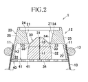
- Figs. 1 and 2 exemplarily show the bodily fluid treating article 1 according to the present invention wherein Fig. 1 is the perspective view of the bodily fluid treating article 1 and Fig. 2 is the schematic sectional view taken along line II-II in Fig. 1 .
- the bodily fluid treating article 1 includes a liquid-impervious container 10 formed with an opening 11 and a backflow preventing mechanism 12 arranged inside the opening 11.
- the container 10 is bag-shaped and made of elastic resin such as natural rubber latex as main raw material.
- the container 10 made of such elastic resin that is extensible under the weight of bodily fluid to enlarge its available internal volume. Bodily fluids flow into the container 10 through the opening 11 formed therein.
- the backflow preventing mechanism 12 includes an annular valve seat member 20 formed along the inner surface of the opening 11, a valve plug 30 formed inside the valve seat member 20 adapted to come in watertight contact with the innermost peripheral edge 23 of a valve port 21 defined by the valve seat member 20 and a supporting member 40 serving to prevent the valve plug 30 from falling off into the container 10.
- the valve port 21 includes the above-mentioned innermost peripheral edge 23 and the outermost peripheral edge 24 as viewed in a diametrical direction of the container 10. More specifically, the valve port 21 slopes up- and outward in the diametrical direction of the container 10 so that the valve port 21 has smallest diameter at the innermost peripheral edge 23 and largest diameter at the outermost peripheral edge 24.
- the valve plug 30 includes an outer peripheral surface 25 opposite to the inner peripheral surface of the valve port 21 and a peripheral wall extending from the outer peripheral surface into the container 10 defines a space forming segment 22.
- the space forming segment 22 forms a space in which the valve plug 30 is movably contained and has a diameter larger than those of the innermost peripheral edge 23 and the outermost peripheral edge 24. Such differential diameter results in the formation of a step between the space forming segment 22 and the innermost peripheral edge 23.
- the valve seat member 20 is preferably formed, for example, of a resin having a sufficient stiffness to maintain an initial shape of the opening 11.
- the term "sufficient stiffness to maintain an initial shape of the opening 11" means the degree of stiffness assuring that at least the shape of the valve port 21 defined by the inner surface of the valve seat member 20 is maintained even when the wearer's body weight is exerted on the valve seat member 20.
- the outer peripheral surface 25 of the valve seat member 20 and the opening 11 of the container 10 are watertightly connected with each other by means of a connector member 13.
- the connector member 13 is formed of, for example, an O-ring made of elastic resin or the like and contractile force thereof functions to press the opening 11 against the outermost peripheral surface 25. It is also possible to connect the outermost peripheral surface 25 to the container 10 with adhesives or the like. In this case, the connector member is defined by adhesives.
- the valve plug 30 is provided in the form of a column extending upward from the space forming segment 22 toward the valve port 21.
- the valve plug 30 includes a small diameter segment 31 having its diameter of the innermost peripheral edge 23, a large diameter segment 32 spaced downward from the small diameter segment 31 into the container 10 and a contact region 33 defined at a level between the small diameter segment 31 and the large diameter segment 32 and adapted to come in contact with the innermost peripheral edge 23.
- the contact region 33 is adapted to come in watertight contact with the innermost peripheral edge 23.
- the valve plug 30 is preferably formed of a flexible resin such as polyurethane.
- the valve plug 30 includes a flat bottom segment 34 lying in the vicinity of a boundary between the backflow preventing mechanism 12 and the container 10.
- the above-mentioned valve plug 30 is set to have a density lower than that of bodily fluids. In consequence, the valve plug 30 can float up from bodily fluids as bodily fluids are collected within the container 10.
- the valve plug 30 is supported by the supporting member 40 so as not to drop off into the container 10.
- the supporting member 40 lies on the side of the valve plug 30 facing the container 10, i.e., on the side of the space forming segment 22 of the valve seat member 20 facing the container 10.
- the supporting member 40 is liquid-pervious. Specifically, a resin plate is formed with a plurality of perforations 41 to obtain the liquid-pervious supporting member 40.
- Material for this supporting member 40 is not particularly specified as long as it is liquid-pervious and it may be appropriately selected from various kinds of materials. For example, liquid-pervious nonwoven fabric may be used as the material for the supporting member 40. In this way, it is assured that bodily fluids can permeate the supporting member 40 into the space forming segment 22.
- a height dimension h1 of the valve plug 30 as measured from the contact region 33 to the bottom segment 34 is set to be smaller than the height h2 of the space forming segment 22 as measured from the innermost peripheral edge 23 to the supporting member 40.
- bodily fluids such as urine discharged toward the valve port 21 flow through a gap defined between the peripheral surface of the small diameter segment 31 of the valve plug 30 and the innermost peripheral edge 23 and then through the perforations 41 of the supporting member 40 into the container since the valve plug 30 is spaced from the innermost peripheral edge 23 of the valve seat member 20.
- the container 10 is made of elastic resin and the weight of bodily fluids being collected gradually increase the volume of the container 10 and thereby prevents the inner volume of the container 10 from being filled with bodily fluids.
- the container 10 is adapted to be dynamically expanded in this manner, so that it is unnecessary to prepare the container 10 having a relatively large volume initially in production steps. Such feature advantageously contributes to make the bodily fluid treating article 1 compact.
- the bodily fluid treating article 1 When the bodily fluid treating article 1 has changed from its posture as illustrated in Figs. 1 and 2 to a posture lying in its side, bodily fluids move through the perforations 41 of the supporting member 40 to the bottom segment 34 of the valve plug 30 and this amount of bodily fluids forces the valve plug 30 to move outward from the side of the container 10.
- the density of the valve plug 30 is lower than that of bodily fluids and, in consequence, the valve plug 30 floats on bodily fluids.
- Floating of the valve plug 30 also serves to drive the valve plug 30 outward from the side of the container 10.
- the contact region 33 comes in contact with the innermost peripheral edge 23 as the valve plug 30 is driven outward from the side of the container 10.
- the valve plug 30 is sufficiently flexible to come in watertight contact with the innermost peripheral edge 23 and to prevent bodily fluids from leaking out of the container 10.
- the bottom segment 34 of the valve plug 30 is pressed by urine and the weight of the container 10 forces the contact region 33 to come in watertight contact with the innermost peripheral edge 23 to prevent bodily fluids from leaking out of the container 10.
- a height dimension h3 as measured from a top of the small diameter segment 31 to the contact region 33 is preferably set to be smaller than a height dimension h4 as measured from the innermost peripheral edge 23 of the valve port 21 to the outermost peripheral edge 24.
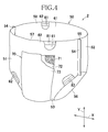
- Figs. 4 through 6 exemplarily illustrate a wearing article including the bodily fluid treating article 1 as has been described above. Details of the wearing article will be described on the basis of a disposable diaper 2 as a typical example thereof.
- Fig. 4 shows the diaper 2 put on the wearer's body and
- Fig. 5 shows the diaper 2 flatly developed after respective opposite side edges thereof have been peeled off one another wherein both Figs. 4 and 5 are partially cutaway for convenience of illustration.
- the diaper 2 is forcibly flattened against contractile force of respective elastics.
- Fig. 6 is a schematic sectional view taken along line VI-VI in Fig. 5 .
- the diaper 2 includes a chassis 50, a liquid-absorbent structure 70, waist elastics 81 and leg elastics 82.
- the chassis 50 includes a front waist region 51, a rear waist region 52 and a crotch region 53 extending between the front and rear waist regions 51, 52 wherein the front waist region 51, the crotch region 53 and the rear waist region 52 are continuously arranged in this order.
- the chassis 50 has a longitudinal center line P-P bisecting a dimension of the diaper 2 in the transverse direction X and a transverse center line Q-Q bisecting a dimension of the diaper 2 in the longitudinal direction Y.
- the chassis 50 includes a bodyside liner 61 defining its side facing the wearer's body and a backsheet 62 defining its side facing the wearer's garment wherein the above-mentioned waist elastics 81 and leg elastics 82 are sandwiched between these bodyside liner 61 and backsheet 62 and bonded to at least one of these bodyside liner 61 and backsheet 62.
- the chassis 50 includes front waist side edges 54 extending in the longitudinal direction Y, rear waist side edges 55 extending in the longitudinal direction Y and leg-opening rim 56 in the longitudinal direction Y in the crotch region 53.
- the leg-opening rim 56 curve toward the longitudinal center line P-P in the crotch region 53 and the leg elastics 82 are attached under tension and in a contractible manner to the leg-opening rim 56 so as to extend therealong.
- the waist elastics 81 are attached under tension and in a contractible manner to the front and rear waist regions 51, 52 along front and rear ends 57, 58 of the chassis extending in the transverse direction X of the front and rear waist regions 51, 52.
- the front waist side edges 54 are joined to the rear waist side edges 55 so that the front and rear waist regions 51, 52 may become contiguous to each other and the diaper 2 may be pants-shaped.
- the chassis 50 is formed at least in the crotch region 53 with a chassis opening 59 extending through the chassis 50 in its thickness direction. According to the present embodiment, the chassis opening 59 extends across the crotch region 53 into the front and rear waist regions 51, 52.
- the liquid-absorbent structure 70 lies on the side of the backsheet 62 facing the wearer's garment so as to close the chassis opening 59.
- the liquid-absorbent structure 70 has both sides facing the wearer's body and the wearer's garment, respectively, and includes a liquid-absorbent core 71 and a wrapping sheet 72 wherein the wrapping sheet 72 is provided on its side facing the wearer's garment with a liquid-impervious leakage-barrier sheet 73.
- the leakage-barrier sheet 73 may be additionally provided on its side facing the wearer's garment with a fibrous nonwoven fabric for improvement of texture.
- the bodyside liner 61 and the backsheet 62 may be formed, for example, of liquid-pervious fibrous nonwoven fabrics
- the liquid-absorbent core 71 may be formed, for example, of a mixture of fluff wood pulp and super-absorbent polymer particles
- the wrapping sheet 72 may be formed, for example, of a liquid-dispersant tissue paper. Otherwise, it is also possible to form these article components of the other types of materials widely used in the relevant technical field.
- the liquid-absorbent core 71 of the liquid-absorbent structure 70 is formed with a liquid-guiding opening 74 extending through the core 71 in its thickness direction so that the liquid-guiding opening 74 may be centrally aligned with the chassis opening 59.
- This liquid-guiding opening 74 is provided with the valve seat member 20 constituting the bodily fluid treating article 1. More specifically, the valve seat member 20 is provided so that the outermost peripheral surface 25 of the valve seat member 20 may fit in the liquid-guiding opening 74 and the container 10 may be located between the liquid-absorbent structure 70 and the leakage-barrier sheet 73.
- the opening 11 of the container 10 is exposed on its side facing the wearer's body by the intermediary of the liquid-guiding opening 74 and faces the wearer's external genitals.
- the wearer's external genitals face the opening 11 of the bodily fluid treating article 1 by the intermediary of the chassis opening 59 and the liquid-guiding opening 74.
- a thickness dimension of the liquid-absorbent core 71 is larger than or equal to the thickness dimension of the bodily fluid treating article 1.
- the term "thickness dimension of the bodily fluid treating article” substantially means a length dimension as measured from the end of the valve seat member 20 facing the wearer's body to the supporting member 40. Such dimensional relationship makes it possible to restrict a possibility that the bodily fluid treating article 1 attached to the liquid-guiding opening 74 might stick out toward the wearer's body through the liquid-guiding opening 74.
- the opening 11 of the bodily fluid treating article 1 is preferably flush with the bodyside liner 61 and the backsheet 62 or lies closer to the wearer's garment than the bodyside liner 61 and backsheet 62.
- urine flows into the container 10 of the bodily fluid treating article 1 through the opening 11.
- the bodily fluid treating article 1 is in the posture as shown in Figs. 1 and 2
- urine flows around the valve plug 30 and then into the container 10.
- the valve plug 30 comes in watertight contact with the valve seat member 20 and thereby the urine once having been collected in the container 10 may be prevented from flowing back toward the side of the wearer's body.
- the liquid-absorbent structure 70 is present around the opening 11 and the urine which has leaked can be absorbed by this liquid-absorbent structure 70. In this manner, urine leakage from the diaper 1 can be further reliably restricted. Only the opening 11 of the bodily fluid treating article 1 is exposed in the liquid-guiding opening 74 of the liquid-absorbent structure 70 and the remainder is held on the side of the wearer's garment so as not to stick out beyond the liquid-absorbent structure 70. With such unique arrangement, an uncomfortable feeling caused by contact of the bodily fluid treating article 1 with the wearer's body can be alleviated by the liquid-absorbent structure 70.
- the bodily fluid treating article 1 is formed with the single opening 11 in the present embodiment, it is possible to form the bodily fluid treating article 1 with two or more openings 11 and it is also possible to provide the wearing article with two or more bodily fluid treating articles 1.
- the liquid-absorbent structure 70 of the diaper 2 is formed with the liquid-guiding opening 74 in which the opening 11 of the bodily fluid treating article 1 is exposed in the present embodiment, it is also possible to locate the bodily fluid treating article 1 as a whole on the side of the liquid-absorbent structure 70 facing the wearer's body. In this case, the bodily fluid treating article 1 can be located between the chassis 50 and the liquid-absorbent structure 70.
- chassis 50 is formed with the chassis opening 59 in the present embodiment, it is not essential to form the chassis opening 59.
- at least a region in which the opening 11 of the bodily fluid treating article is located may be made liquid-pervious to assure that bodily fluids such as urine can permeate the bodily fluid treating article 1 located on the side of the chassis 50 facing the wearer's garment. It is also possible to form the bodily fluid treating article 1 on the side of the chassis 50 facing the wearer's body. In either case, it is essential that bodily fluids such as urine can be reliably collected through the opening 11 of the bodily fluid treating article 1 into the container 10. Though a liquid-impervious container is used as the container 20 in the present embodiment, it is not limited thereto.
- the container 10 is capable to contain bodily fluids flowing thereinto through the opening 11, it is possible to use a liquid pervious container, and in such a case, the liquid-absorbent core may be used to contain bodily fluids once collected in such a liquid pervious container.
- valve seat member 20 and the supporting member 40 are formed of the members separately prepared and then joined together in the present embodiment, it is also possible to form these two members 20, 40 integrally.
- valve seat member 20 and the supporting member 40 are integrally formed, it is also possible to form both members by one and the same kind of material in the form of a single member.
Landscapes
- Health & Medical Sciences (AREA)
- Animal Behavior & Ethology (AREA)
- Life Sciences & Earth Sciences (AREA)
- Veterinary Medicine (AREA)
- Engineering & Computer Science (AREA)
- Biomedical Technology (AREA)
- Heart & Thoracic Surgery (AREA)
- Vascular Medicine (AREA)
- Public Health (AREA)
- Epidemiology (AREA)
- General Health & Medical Sciences (AREA)
- Nursing (AREA)
- Orthopedic Medicine & Surgery (AREA)
- Orthopedics, Nursing, And Contraception (AREA)
- Absorbent Articles And Supports Therefor (AREA)
Abstract
The present invention provides a bodily fluid treating article improved so as to assure that bodily fluids do not leak therefrom particularly when the wearer's body weight is exerted thereon or the wearer's posture changes, and a wearing article including the same. A bodily fluid treating article 1 is attached to a diaper 2 of a wearing article. A bodyside liner 61 and a backsheet 62 of the diaper 2 are formed with a chassis opening 59 extending therethrough in a thickness direction of them. A liquid-absorbent core 71 of a liquid-absorbent structure 70 is formed with a liquid-guiding opening 74 extending therethrough so as to be centrally aligned with the chassis opening 59. Within the liquid-guiding opening 74, a valve seat member 20 is provided as a component of the bodily fluid treating article 1 so that the outermost peripheral edge 25 of the valve seat member 20 may fit in the liquid-guiding opening 74. The opening 11 of the container 10 is exposed on the side facing the wearer's body by the intermediary of the liquid-guiding opening 74 and faces the wearer's external genitals.
Description
- The present invention relates to bodily fluid treating articles and wearing articles including the same, and more particularly to disposable diapers, toilet-training pants, incontinent briefs and the like including bodily fluid treating articles.
- Conventionally, it is well known, for example, from
JP 2005-323797A - {PTL 1}
JP 2005-323797A - In the case of the above-mentioned absorbent article of prior art, urine once having been absorbed by the absorbent article partially leaches out from the absorbent structure, for example, under the wearer's body weight exerted thereon. With the absorbent structure from which urine is leaching out in this manner, there is a possibility that the urine once having been contained might move within the bag-shaped absorbent article and eventually leak out from the article through the opening if the wearer turns over on his or her side or gets down on all fours.
- An object of the present invention is to provide a bodily fluid treating article improved so as to assure that bodily fluids do not leak from the bodily fluid treating article even when the wearer's body weight is exerted thereon or the wearer's posture changes and a wearing article including the same.
- The present invention includes a first aspect and a second aspect.
The present invention in the first aspect thereof relates to an improvement in a bodily fluid treating article having an opening through which bodily fluids flow into the article and including a container adapted to contain the bodily fluids flowing into the article. - The present invention in the first aspect thereof is characterized in that the bodily fluid treating article includes backflow preventing means adapted to restrict the possibility that bodily fluids once having been collected within the container might flow back from the container through the opening; the back flow preventing means includes a valve seat member located in the opening, a valve plug adapted to come in watertight contact with the valve seat member and a supporting member serving to prevent the valve plug from falling into the container wherein the bodily fluids can flow into the container when the valve seat member and the valve plug are spaced from each other.
The valve seat member and the supporting member may be formed of separately prepared members and then joined together or formed integrally of one and the same kind of material in the form of a single member. - The present invention in the first aspect thereof includes preferred embodiments as follows:
- (1) The valve seat member includes a valve port extending from the interior to the exterior of the container; and the valve plug includes a small diameter segment having a diameter smaller than a diameter of the valve port, a contact region adapted to come in watertight contact with the valve port and a large diameter segment having a diameter larger than that of the valve port wherein the contact region is defined between the small diameter segment and the large diameter segment of the valve plug, and the small diameter segment is located on a side facing outward from the container and the large diameter segment is located on a side facing inward of the container.
- (2) The valve plug has its density lower than a density of the bodily fluids.
- (3) The supporting member has liquid-permeability and to be located on the side of valve plug facing inward of the container.
- The present invention in the second aspect thereof relates to an improvement in a wearing article including a chassis which includes a longitudinal direction, a transverse direction, a side facing the wearer's body, a side facing away from the wearer's body, a front waist region, a rear waist region and a crotch region extending between the front and rear waist regions wherein the front waist region, the crotch region and the rear waist region are continuous in this order.
The present invention in the second aspect thereof is characterized in that the wearing article includes the bodily fluid treating article at least in the crotch region; and the opening of the bodily fluid treating article opens on the side facing the wearer's body. - The present invention in the second aspect thereof includes preferred embodiments as follows:
- (1) The chassis includes a chassis opening formed in the crotch region and centrally aligned with the opening of the bodily fluid treating article, and the container lies on the side facing away from the wearer's body.
- (2) The wearing article includes a liquid-absorbent structure at least in the crotch region; the liquid-absorbent structure includes a side facing the wearer's body, a side facing away from the wearer's body and a liquid-guiding opening extending through the liquid-absorbent structure; and the liquid-guiding opening is centrally aligned with the opening of the bodily fluid treating article and the container is located on the side opposite to the liquid-absorbent structure.
- In the bodily fluid treating article according to the present invention in its first aspect, bodily fluids discharged by the wearer can reliably flow into the container and the bodily fluids once having been collected therein are prevented by the backflow preventing means from flowing back from the container. With this arrangement, leakage of bodily fluids from the container can be effectively prevented. The bodily fluid treating article includes a valve plug provided in the opening of the container so that this valve plug is adapted to come in watertight contact with the valve seat member. With this unique arrangement, leakage of bodily fluids from the container can be effectively restricted by the valve plug when coming in watertight contact with the valve seat member.
- In the wearing article according to the present invention in its second aspect, the bodily fluid treating article is located at least in the crotch region so that the opening of the container opens toward the side facing the wearer's body. With this arrangement, when a diaper is used, for example, as the wearing article, urine discharged by the wearer can be contained in the bodily fluid treating article. In consequence, leakage of bodily fluids such as urine from the wearing article can be reliably restricted.
-
- {
Fig. 1 } Perspective view of a bodily fluid treating article. - {
Fig. 2 } Schematic sectional view taken along line II-II inFig. 1 . - {
Fig. 3 } Diagram illustrating the bodily fluid treating article. {Fig. 4 } Perspective view showing a diaper as put on the wearer's body. - {
Fig. 5 } Developed plan view of the diaper. - {
Fig. 6 Schematic sectional view taken along line VI-VI inFig. 5 . -
Figs. 1 and2 exemplarily show the bodilyfluid treating article 1 according to the present invention whereinFig. 1 is the perspective view of the bodilyfluid treating article 1 andFig. 2 is the schematic sectional view taken along line II-II inFig. 1 . As will be apparent fromFigs. 1 and2 , the bodilyfluid treating article 1 includes a liquid-impervious container 10 formed with anopening 11 and abackflow preventing mechanism 12 arranged inside theopening 11. - The
container 10 is bag-shaped and made of elastic resin such as natural rubber latex as main raw material. Thecontainer 10 made of such elastic resin that is extensible under the weight of bodily fluid to enlarge its available internal volume. Bodily fluids flow into thecontainer 10 through the opening 11 formed therein. - The
backflow preventing mechanism 12 includes an annularvalve seat member 20 formed along the inner surface of theopening 11, avalve plug 30 formed inside thevalve seat member 20 adapted to come in watertight contact with the innermostperipheral edge 23 of avalve port 21 defined by thevalve seat member 20 and a supportingmember 40 serving to prevent thevalve plug 30 from falling off into thecontainer 10. Thevalve port 21 includes the above-mentioned innermostperipheral edge 23 and the outermostperipheral edge 24 as viewed in a diametrical direction of thecontainer 10. More specifically, thevalve port 21 slopes up- and outward in the diametrical direction of thecontainer 10 so that thevalve port 21 has smallest diameter at the innermostperipheral edge 23 and largest diameter at the outermostperipheral edge 24. Thevalve plug 30 includes an outerperipheral surface 25 opposite to the inner peripheral surface of thevalve port 21 and a peripheral wall extending from the outer peripheral surface into thecontainer 10 defines aspace forming segment 22. Thespace forming segment 22 forms a space in which thevalve plug 30 is movably contained and has a diameter larger than those of the innermostperipheral edge 23 and the outermostperipheral edge 24. Such differential diameter results in the formation of a step between thespace forming segment 22 and the innermostperipheral edge 23. - The
valve seat member 20 is preferably formed, for example, of a resin having a sufficient stiffness to maintain an initial shape of theopening 11. The term "sufficient stiffness to maintain an initial shape of the opening 11" means the degree of stiffness assuring that at least the shape of thevalve port 21 defined by the inner surface of thevalve seat member 20 is maintained even when the wearer's body weight is exerted on thevalve seat member 20. By maintaining the shape of thevalve port 21, it is possible to restrict formation of a gap between thevalve plug 30 and the innermostperipheral edge 23 of thevalve seat member 20 when thevalve plug 30 comes in contact with the innermostperipheral edge 23 of thevalve seat member 20.
The outerperipheral surface 25 of thevalve seat member 20 and theopening 11 of thecontainer 10 are watertightly connected with each other by means of aconnector member 13. Theconnector member 13 is formed of, for example, an O-ring made of elastic resin or the like and contractile force thereof functions to press theopening 11 against the outermostperipheral surface 25. It is also possible to connect the outermostperipheral surface 25 to thecontainer 10 with adhesives or the like. In this case, the connector member is defined by adhesives. - The
valve plug 30 is provided in the form of a column extending upward from thespace forming segment 22 toward thevalve port 21. Thevalve plug 30 includes asmall diameter segment 31 having its diameter of the innermostperipheral edge 23, alarge diameter segment 32 spaced downward from thesmall diameter segment 31 into thecontainer 10 and acontact region 33 defined at a level between thesmall diameter segment 31 and thelarge diameter segment 32 and adapted to come in contact with the innermostperipheral edge 23. Thecontact region 33 is adapted to come in watertight contact with the innermostperipheral edge 23. To assure that thecontact region 33 can come in watertight contact with the innermostperipheral edge 23 of thevalve seat member 20, thevalve plug 30 is preferably formed of a flexible resin such as polyurethane. Thevalve plug 30 includes aflat bottom segment 34 lying in the vicinity of a boundary between thebackflow preventing mechanism 12 and thecontainer 10. - The above-mentioned
valve plug 30 is set to have a density lower than that of bodily fluids. In consequence, thevalve plug 30 can float up from bodily fluids as bodily fluids are collected within thecontainer 10. Thevalve plug 30 is supported by the supportingmember 40 so as not to drop off into thecontainer 10. The supportingmember 40 lies on the side of thevalve plug 30 facing thecontainer 10, i.e., on the side of thespace forming segment 22 of thevalve seat member 20 facing thecontainer 10. The supportingmember 40 is liquid-pervious. Specifically, a resin plate is formed with a plurality ofperforations 41 to obtain the liquid-pervious supporting member 40. Material for this supportingmember 40 is not particularly specified as long as it is liquid-pervious and it may be appropriately selected from various kinds of materials. For example, liquid-pervious nonwoven fabric may be used as the material for the supportingmember 40. In this way, it is assured that bodily fluids can permeate the supportingmember 40 into thespace forming segment 22. - A height dimension h1 of the
valve plug 30 as measured from thecontact region 33 to thebottom segment 34 is set to be smaller than the height h2 of thespace forming segment 22 as measured from the innermostperipheral edge 23 to the supportingmember 40. In consequence, assuming that the supportingmember 40 is lowly-placed and thevalve plug 30 is highly-placed as illustrated inFig. 2 , thecontact region 33 of thevalve plug 30 will be spaced from the innermostperipheral edge 23 of thevalve seat member 20 and thebottom segment 34 of thevalve plug 30 will be held in contact with the supportingmember 40. - When the above-mentioned bodily
fluid treating article 1 is in the state as illustrated inFigs. 1 and2 , bodily fluids such as urine discharged toward thevalve port 21 flow through a gap defined between the peripheral surface of thesmall diameter segment 31 of thevalve plug 30 and the innermostperipheral edge 23 and then through theperforations 41 of the supportingmember 40 into the container since thevalve plug 30 is spaced from the innermostperipheral edge 23 of thevalve seat member 20. Thecontainer 10 is made of elastic resin and the weight of bodily fluids being collected gradually increase the volume of thecontainer 10 and thereby prevents the inner volume of thecontainer 10 from being filled with bodily fluids. Thecontainer 10 is adapted to be dynamically expanded in this manner, so that it is unnecessary to prepare thecontainer 10 having a relatively large volume initially in production steps. Such feature advantageously contributes to make the bodilyfluid treating article 1 compact. - When the bodily
fluid treating article 1 has changed from its posture as illustrated inFigs. 1 and2 to a posture lying in its side, bodily fluids move through theperforations 41 of the supportingmember 40 to thebottom segment 34 of thevalve plug 30 and this amount of bodily fluids forces thevalve plug 30 to move outward from the side of thecontainer 10. In addition, the density of thevalve plug 30 is lower than that of bodily fluids and, in consequence, thevalve plug 30 floats on bodily fluids. Floating of thevalve plug 30 also serves to drive thevalve plug 30 outward from the side of thecontainer 10. Thecontact region 33 comes in contact with the innermostperipheral edge 23 as thevalve plug 30 is driven outward from the side of thecontainer 10. Thevalve plug 30 is sufficiently flexible to come in watertight contact with the innermostperipheral edge 23 and to prevent bodily fluids from leaking out of thecontainer 10.
When thecontainer 10 is placed upside down, thebottom segment 34 of thevalve plug 30 is pressed by urine and the weight of thecontainer 10 forces thecontact region 33 to come in watertight contact with the innermostperipheral edge 23 to prevent bodily fluids from leaking out of thecontainer 10. - In the above-mentioned bodily
fluid treating article 1, a height dimension h3 as measured from a top of thesmall diameter segment 31 to thecontact region 33 is preferably set to be smaller than a height dimension h4 as measured from the innermostperipheral edge 23 of thevalve port 21 to the outermostperipheral edge 24. Such dimensional relationship assures that the top does not stick out beyond the outermostperipheral edge 24 when thecontact region 33 of thevalve plug 30 comes in contact with the innermostperipheral edge 23 of thevalve seat member 20. Therefore, the top of thevalve plug 30 should not come in contact with the wearer's skin and cause skin troubles. Even if thevalve plug 30 comes in contact with the wearer's skin, an impact can be alleviated since thevalve plug 30 is formed of flexible resin. -
Figs. 4 through 6 exemplarily illustrate a wearing article including the bodilyfluid treating article 1 as has been described above. Details of the wearing article will be described on the basis of adisposable diaper 2 as a typical example thereof.
Fig. 4 shows thediaper 2 put on the wearer's body andFig. 5 shows thediaper 2 flatly developed after respective opposite side edges thereof have been peeled off one another wherein bothFigs. 4 and5 are partially cutaway for convenience of illustration. InFig. 5 , thediaper 2 is forcibly flattened against contractile force of respective elastics.Fig. 6 is a schematic sectional view taken along line VI-VI inFig. 5 . Thediaper 2 includes achassis 50, a liquid-absorbent structure 70, waist elastics 81 andleg elastics 82. Thechassis 50 includes afront waist region 51, arear waist region 52 and acrotch region 53 extending between the front andrear waist regions front waist region 51, thecrotch region 53 and therear waist region 52 are continuously arranged in this order. In addition, thechassis 50 has a longitudinal center line P-P bisecting a dimension of thediaper 2 in the transverse direction X and a transverse center line Q-Q bisecting a dimension of thediaper 2 in the longitudinal direction Y. - The
chassis 50 includes abodyside liner 61 defining its side facing the wearer's body and abacksheet 62 defining its side facing the wearer's garment wherein the above-mentionedwaist elastics 81 and leg elastics 82 are sandwiched between thesebodyside liner 61 andbacksheet 62 and bonded to at least one of thesebodyside liner 61 andbacksheet 62. Thechassis 50 includes front waist side edges 54 extending in the longitudinal direction Y, rear waist side edges 55 extending in the longitudinal direction Y and leg-openingrim 56 in the longitudinal direction Y in thecrotch region 53. - The leg-opening
rim 56 curve toward the longitudinal center line P-P in thecrotch region 53 and theleg elastics 82 are attached under tension and in a contractible manner to the leg-openingrim 56 so as to extend therealong. The waist elastics 81 are attached under tension and in a contractible manner to the front andrear waist regions rear ends rear waist regions rear waist regions diaper 2 may be pants-shaped. - The
chassis 50 is formed at least in thecrotch region 53 with achassis opening 59 extending through thechassis 50 in its thickness direction. According to the present embodiment, thechassis opening 59 extends across thecrotch region 53 into the front andrear waist regions absorbent structure 70 lies on the side of thebacksheet 62 facing the wearer's garment so as to close thechassis opening 59. The liquid-absorbent structure 70 has both sides facing the wearer's body and the wearer's garment, respectively, and includes a liquid-absorbent core 71 and awrapping sheet 72 wherein thewrapping sheet 72 is provided on its side facing the wearer's garment with a liquid-impervious leakage-barrier sheet 73. The leakage-barrier sheet 73 may be additionally provided on its side facing the wearer's garment with a fibrous nonwoven fabric for improvement of texture. Thebodyside liner 61 and thebacksheet 62 may be formed, for example, of liquid-pervious fibrous nonwoven fabrics, the liquid-absorbent core 71 may be formed, for example, of a mixture of fluff wood pulp and super-absorbent polymer particles and thewrapping sheet 72 may be formed, for example, of a liquid-dispersant tissue paper. Otherwise, it is also possible to form these article components of the other types of materials widely used in the relevant technical field. - The liquid-
absorbent core 71 of the liquid-absorbent structure 70 is formed with a liquid-guidingopening 74 extending through the core 71 in its thickness direction so that the liquid-guidingopening 74 may be centrally aligned with thechassis opening 59. This liquid-guidingopening 74 is provided with thevalve seat member 20 constituting the bodilyfluid treating article 1. More specifically, thevalve seat member 20 is provided so that the outermostperipheral surface 25 of thevalve seat member 20 may fit in the liquid-guidingopening 74 and thecontainer 10 may be located between the liquid-absorbent structure 70 and the leakage-barrier sheet 73. Theopening 11 of thecontainer 10 is exposed on its side facing the wearer's body by the intermediary of the liquid-guidingopening 74 and faces the wearer's external genitals. In consequence, the wearer's external genitals face theopening 11 of the bodilyfluid treating article 1 by the intermediary of thechassis opening 59 and the liquid-guidingopening 74. - A thickness dimension of the liquid-
absorbent core 71 is larger than or equal to the thickness dimension of the bodilyfluid treating article 1. The term "thickness dimension of the bodily fluid treating article" substantially means a length dimension as measured from the end of thevalve seat member 20 facing the wearer's body to the supportingmember 40. Such dimensional relationship makes it possible to restrict a possibility that the bodilyfluid treating article 1 attached to the liquid-guidingopening 74 might stick out toward the wearer's body through the liquid-guidingopening 74. Theopening 11 of the bodilyfluid treating article 1 is preferably flush with thebodyside liner 61 and thebacksheet 62 or lies closer to the wearer's garment than thebodyside liner 61 andbacksheet 62. - Upon occurrence of urination onto the
diaper 2 having been described above, urine flows into thecontainer 10 of the bodilyfluid treating article 1 through theopening 11. When the bodilyfluid treating article 1 is in the posture as shown inFigs. 1 and2 , urine flows around thevalve plug 30 and then into thecontainer 10. When the posture of the bodilyfluid treating article 1 changes from the upright posture to the posture as shown inFig. 3 as the wearer has a lie-down or gets down on all fours, thevalve plug 30 comes in watertight contact with thevalve seat member 20 and thereby the urine once having been collected in thecontainer 10 may be prevented from flowing back toward the side of the wearer's body. If the wearer's body weight is exerted on the bodilyfluid treating article 1, for example, as the wearer gets seated, a level of urine certainly rises but thevalve plug 30 having its density lower than that of bodily fluids can float on urine. Consequently, thevalve plug 30 comes in contact with thevalve seat member 20 before urine could flow out from thecontainer 10. In this way, even in such case, it is possible to prevent urine from flowing back out of the bodilyfluid treating article 1 and thereby urine leakage from thediaper 2 can be restricted. - Even if urination might occur besides the
opening 11 of the bodilyfluid treating article 1 or urine might leak out from thecontainer 10, the liquid-absorbent structure 70 is present around theopening 11 and the urine which has leaked can be absorbed by this liquid-absorbent structure 70. In this manner, urine leakage from thediaper 1 can be further reliably restricted.
Only theopening 11 of the bodilyfluid treating article 1 is exposed in the liquid-guidingopening 74 of the liquid-absorbent structure 70 and the remainder is held on the side of the wearer's garment so as not to stick out beyond the liquid-absorbent structure 70. With such unique arrangement, an uncomfortable feeling caused by contact of the bodilyfluid treating article 1 with the wearer's body can be alleviated by the liquid-absorbent structure 70. - While the bodily
fluid treating article 1 is formed with thesingle opening 11 in the present embodiment, it is possible to form the bodilyfluid treating article 1 with two ormore openings 11 and it is also possible to provide the wearing article with two or more bodilyfluid treating articles 1.
While the liquid-absorbent structure 70 of thediaper 2 is formed with the liquid-guidingopening 74 in which theopening 11 of the bodilyfluid treating article 1 is exposed in the present embodiment, it is also possible to locate the bodilyfluid treating article 1 as a whole on the side of the liquid-absorbent structure 70 facing the wearer's body. In this case, the bodilyfluid treating article 1 can be located between thechassis 50 and the liquid-absorbent structure 70.
While thechassis 50 is formed with thechassis opening 59 in the present embodiment, it is not essential to form thechassis opening 59. In that case, at least a region in which theopening 11 of the bodily fluid treating article is located may be made liquid-pervious to assure that bodily fluids such as urine can permeate the bodilyfluid treating article 1 located on the side of thechassis 50 facing the wearer's garment. It is also possible to form the bodilyfluid treating article 1 on the side of thechassis 50 facing the wearer's body. In either case, it is essential that bodily fluids such as urine can be reliably collected through theopening 11 of the bodilyfluid treating article 1 into thecontainer 10. Though a liquid-impervious container is used as thecontainer 20 in the present embodiment, it is not limited thereto. As long as thecontainer 10 is capable to contain bodily fluids flowing thereinto through theopening 11, it is possible to use a liquid pervious container, and in such a case, the liquid-absorbent core may be used to contain bodily fluids once collected in such a liquid pervious container. - While the
valve seat member 20 and the supportingmember 40 are formed of the members separately prepared and then joined together in the present embodiment, it is also possible to form these twomembers valve seat member 20 and the supportingmember 40 are integrally formed, it is also possible to form both members by one and the same kind of material in the form of a single member. -
- 1
- bodily fluid treating article
- 2
- diaper (wearing article)
- 10
- container
- 11
- chassis opening
- 12
- backflow preventing mechanism
- 20
- valve seat member
- 21
- valve port
- 30
- valve plug
- 31
- small diameter segment
- 32
- large diameter segment
- 33
- contact region
- 40
- supporting member
- 50
- chassis
- 51
- front waist region
- 52
- rear waist region
- 53
- crotch region
- 59
- chassis opening
- 70
- liquid-absorbent structure
- 74
- liquid-guiding opening
Claims (7)
- A bodily fluid treating article having an opening through which bodily fluids flow into the article and an absorbent structure adapted to contain the bodily fluids flowing into the article, the bodily fluid treating article being characterized in that:the bodily fluid treating article includes backflow preventing means adapted to restrict a possibility that the bodily fluids once having been collected within the container might flow back from the container through the opening;the backflow preventing means comprises a valve seat member located in the opening, a valve plug adapted to come in watertight contact with the valve seat member and a supporting member serving to prevent the valve plug from falling into the container wherein the bodily fluids can flow into the container when the valve seat member and the valve plug are spaced from each other.
- The bodily fluid treating article defined by claim 1, wherein:the valve seat member includes a valve port extending from the interior to the exterior of the container;and the valve plug comprises a small diameter segment having a diameter smaller than a diameter of the valve port, a contact region adapted to come in watertight contact with the valve port and a large diameter segment having a diameter larger than the diameter of the valve port wherein the contact region is defined between the small diameter segment and the large diameter segment of the valve plug, the small diameter segment defined at a level of the valve plug more remote than the large diameter segment outward from the container.
- The bodily fluid treating article defined by claim 1 or 2, wherein the valve plug is set to have its density lower than a density of the bodily fluids.
- The bodily fluid treating article defined by any one of claims 1 through 3, wherein the supporting member is liquid pervious and located on the side of the valve plug facing the container.
- A wearing article including a chassis which comprises a longitudinal direction, a transverse direction, a side facing the wearer's body, a side facing away from the wearer's body, a front waist region, a rear waist region and a crotch region extending between the front and rear waist regions wherein the front waist region, the crotch region and the rear waist region are continuous in this order, the wearing article being characterized in that:the wearing article includes the bodily fluid treating article defined by claim 1 at least in the crotch region; andthe opening of the bodily fluid treating article opens on the side facing the wearer's body.
- The wearing article defined by claim 5, wherein the chassis includes a chassis opening formed in the crotch region and centrally aligned with the opening of the bodily fluid treating article and the container lies on the side facing away from the wearer's body.
- The wearing article defined by claim 5 or 6, wherein:the wearing article includes a liquid-absorbent structure at least in the crotch region;the liquid-guiding opening is centrally aligned with the opening of the bodily fluid treating article and the container is located on the side opposite to the liquid-absorbent structure.
Applications Claiming Priority (2)
| Application Number | Priority Date | Filing Date | Title |
|---|---|---|---|
| JP2009017328A JP5280226B2 (en) | 2009-01-28 | 2009-01-28 | Body fluid treatment article and wearing article including the same |
| PCT/JP2009/007044 WO2010086947A1 (en) | 2009-01-28 | 2009-12-21 | Bodily fluid treating article and wearing article including same |
Publications (1)
| Publication Number | Publication Date |
|---|---|
| EP2392297A1 true EP2392297A1 (en) | 2011-12-07 |
Family
ID=42395218
Family Applications (1)
| Application Number | Title | Priority Date | Filing Date |
|---|---|---|---|
| EP09839139A Withdrawn EP2392297A1 (en) | 2009-01-28 | 2009-12-21 | Bodily fluid treating article and wearing article including same |
Country Status (5)
| Country | Link |
|---|---|
| US (1) | US20110276020A1 (en) |
| EP (1) | EP2392297A1 (en) |
| JP (1) | JP5280226B2 (en) |
| CN (1) | CN102300522A (en) |
| WO (1) | WO2010086947A1 (en) |
Families Citing this family (62)
| Publication number | Priority date | Publication date | Assignee | Title |
|---|---|---|---|---|
| US10390989B2 (en) | 2014-03-19 | 2019-08-27 | Purewick Corporation | Apparatus and methods for receiving discharged urine |
| US10952889B2 (en) | 2016-06-02 | 2021-03-23 | Purewick Corporation | Using wicking material to collect liquid for transport |
| US10226376B2 (en) | 2014-03-19 | 2019-03-12 | Purewick Corporation | Apparatus and methods for receiving discharged urine |
| KR101730786B1 (en) * | 2014-04-30 | 2017-04-27 | 킴벌리-클라크 월드와이드, 인크. | Absorbent article including a fluid distributing structure |
| CN104523376A (en) * | 2015-01-19 | 2015-04-22 | 陆继儒 | Novel environmentally friendly baby diaper series achieving dry, comfortable and energy-saving effects |
| GB2553221A (en) | 2015-11-03 | 2018-02-28 | Siller Gonzalez Andrea | Device for collecting urine samples for dependent patients |
| US10376406B2 (en) | 2016-07-27 | 2019-08-13 | Purewick Corporation | Male urine collection device using wicking material |
| CN110612075B (en) | 2017-01-31 | 2022-09-09 | 普利维克公司 | Apparatus and method for receiving excreted urine |
| CA3098571C (en) | 2018-05-01 | 2023-09-26 | Purewick Corporation | Fluid collection devices, systems, and methods |
| AU2019262945B2 (en) | 2018-05-01 | 2022-08-25 | Purewick Corporation | Fluid collection devices and methods of using the same |
| US11944740B2 (en) | 2018-05-01 | 2024-04-02 | Purewick Corporation | Fluid collection devices, related systems, and related methods |
| US12575961B2 (en) | 2018-05-01 | 2026-03-17 | Purewick Corporation | Fluid collection devices, systems, and methods |
| JP7072084B2 (en) | 2018-05-01 | 2022-05-19 | ピュアウィック コーポレイション | Fluid collectors, related systems, and related methods |
| AU2019262946B2 (en) | 2018-05-02 | 2022-06-23 | Purewick Corporation | Fluid collection devices, systems, and methods |
| WO2020021340A2 (en) * | 2018-07-25 | 2020-01-30 | Benkartoussa Mohammed Kamel | Disposable septic diaper |
| CA3143904C (en) | 2019-06-21 | 2023-11-28 | Purewick Corporation | Fluid collection devices including a base securement area, and related systems and methods |
| CN114375187A (en) | 2019-07-11 | 2022-04-19 | 普奥维克有限公司 | Fluid collection devices, systems, and methods |
| ES2980959T3 (en) | 2019-07-19 | 2024-10-03 | Purewick Corp | Fluid collection devices including at least one shape memory material |
| EP4051190B1 (en) | 2019-10-28 | 2024-05-22 | Purewick Corporation | Fluid collection assemblies including a sample port |
| EP4084746B1 (en) | 2020-01-03 | 2025-04-02 | Purewick Corporation | Urine collection devices having a relatively wide portion and an elongated portion and related methods cross-reference to related applications |
| WO2021155206A1 (en) | 2020-01-30 | 2021-08-05 | Purewick Corporation | Fluid collection assemblies including a skirt cross-reference to related applications |
| US12589022B2 (en) | 2020-03-19 | 2026-03-31 | Purewick Corporation | Fluid collection assemblies including one or more movement enhancing features |
| WO2021195384A1 (en) | 2020-03-26 | 2021-09-30 | Purewick Corporation | Multi-layered urine capture device and related methods |
| WO2021207621A1 (en) | 2020-04-10 | 2021-10-14 | Purewick Corporation | Fluid collection assemblies including one or more leak prevention features |
| US12465514B2 (en) | 2020-04-17 | 2025-11-11 | Purewick Corporation | Fluid collection devices, systems, and methods securing a protruding portion in position for use |
| US12447042B2 (en) | 2020-04-17 | 2025-10-21 | Purewick Corporation | Fluid collection assemblies including a fluid impermeable barrier having a sump and a base |
| US12472090B2 (en) | 2020-04-17 | 2025-11-18 | Purewick Corporation | Female external catheter devices having a urethral cup, and related systems and methods |
| WO2021216422A1 (en) | 2020-04-20 | 2021-10-28 | Purewick Corporation | Fluid collection devices adjustable between a vacuum- based orientation and a gravity-based orientation, and related systems and methods |
| US12048643B2 (en) | 2020-05-27 | 2024-07-30 | Purewick Corporation | Fluid collection assemblies including at least one inflation device and methods and systems of using the same |
| US12685663B2 (en) | 2020-08-05 | 2026-07-21 | Purewick Corporation | Fluid collection devices including an enlarged base, and systems and methods of use |
| WO2022031943A1 (en) | 2020-08-06 | 2022-02-10 | Purewick Corporation | A fluid collection system including a garment and a fluid collection device |
| US20220047410A1 (en) * | 2020-08-11 | 2022-02-17 | Purewick Corporation | Fluid collection assemblies defining waist and leg openings |
| WO2022035745A1 (en) | 2020-08-11 | 2022-02-17 | Purewick Corporation | Fluid collection devices and methods of manufacturing same cross-reference to related applications |
| WO2022055957A1 (en) | 2020-09-09 | 2022-03-17 | Purewick Corporation | Fluid collection devices, systems, and methods |
| US12156792B2 (en) | 2020-09-10 | 2024-12-03 | Purewick Corporation | Fluid collection assemblies including at least one inflation device |
| US12042423B2 (en) | 2020-10-07 | 2024-07-23 | Purewick Corporation | Fluid collection systems including at least one tensioning element |
| US12208031B2 (en) | 2020-10-21 | 2025-01-28 | Purewick Corporation | Adapters for fluid collection devices |
| US12257174B2 (en) | 2020-10-21 | 2025-03-25 | Purewick Corporation | Fluid collection assemblies including at least one of a protrusion or at least one expandable material |
| US12569365B2 (en) | 2020-10-21 | 2026-03-10 | Purewick Corporation | Fluid collection assemblies including at least one shape memory material disposed in the conduit |
| US12440370B2 (en) | 2020-10-21 | 2025-10-14 | Purewick Corporation | Apparatus with compressible casing for receiving discharged urine |
| US12048644B2 (en) | 2020-11-03 | 2024-07-30 | Purewick Corporation | Apparatus for receiving discharged urine |
| US12070432B2 (en) | 2020-11-11 | 2024-08-27 | Purewick Corporation | Urine collection system including a flow meter and related methods |
| US12245967B2 (en) | 2020-11-18 | 2025-03-11 | Purewick Corporation | Fluid collection assemblies including an adjustable spine |
| US12599495B2 (en) | 2021-01-05 | 2026-04-14 | Purewick Corporation | Male external catheter with attachment interface configured to bias against penis |
| US12268627B2 (en) | 2021-01-06 | 2025-04-08 | Purewick Corporation | Fluid collection assemblies including at least one securement body |
| CN116940312A (en) | 2021-01-07 | 2023-10-24 | 普利维克公司 | Wheelchair-mounted urine collection system and related method |
| ES2975761T3 (en) | 2021-01-19 | 2024-07-15 | Purewick Corp | Variable adjustment liquid collection device |
| US12178735B2 (en) | 2021-02-09 | 2024-12-31 | Purewick Corporation | Noise reduction for a urine suction system |
| JP2023553620A (en) | 2021-02-26 | 2023-12-25 | ピュアウィック コーポレイション | Fluid collection device having a drainage basin between a pipe opening and a barrier, and related systems and methods |
| US12558472B2 (en) | 2021-03-05 | 2026-02-24 | Purewick Corporation | Portable fluid collection systems with storage and related methods |
| US12551385B2 (en) | 2021-03-05 | 2026-02-17 | Purewick Corporation | Fluid collection assembly including a tube having porous wicking material for improved fluid transport |
| US12458525B2 (en) | 2021-03-10 | 2025-11-04 | Purewick Corporation | Acoustic silencer for a urine suction system |
| US12029677B2 (en) | 2021-04-06 | 2024-07-09 | Purewick Corporation | Fluid collection devices having a collection bag, and related systems and methods |
| MX2023011851A (en) | 2021-04-09 | 2023-10-19 | Purewick Corp | Conduits including at least one conduit porous material. |
| US12233003B2 (en) | 2021-04-29 | 2025-02-25 | Purewick Corporation | Fluid collection assemblies including at least one length adjusting feature |
| US12251333B2 (en) | 2021-05-21 | 2025-03-18 | Purewick Corporation | Fluid collection assemblies including at least one inflation device and methods and systems of using the same |
| US12324767B2 (en) | 2021-05-24 | 2025-06-10 | Purewick Corporation | Fluid collection assembly including a customizable external support and related methods |
| US12150885B2 (en) | 2021-05-26 | 2024-11-26 | Purewick Corporation | Fluid collection system including a cleaning system and methods |
| US12575960B2 (en) | 2021-06-24 | 2026-03-17 | Purewick Corporation | Urine collection systems having one or more of volume, pressure, or flow indicators, and related methods |
| US12551366B2 (en) | 2021-08-02 | 2026-02-17 | Purewick Corporation | Fluid collection devices having multiple fluid collection regions, and related systems and methods |
| JP2024528975A (en) | 2021-08-02 | 2024-08-01 | ピュアウィック コーポレイション | Molded or extruded fluid collection devices and related systems and methods - Patents.com |
| US12594062B2 (en) | 2021-09-08 | 2026-04-07 | Purewick Corporation | Fluid collection assemblies including an extension |
Family Cites Families (17)
| Publication number | Priority date | Publication date | Assignee | Title |
|---|---|---|---|---|
| US3532093A (en) * | 1968-04-22 | 1970-10-06 | Rose Lovret | Separable compartmented diaper construction |
| US4676785A (en) * | 1985-10-21 | 1987-06-30 | Battista Orlando A | Liquid retaining absorbent structure |
| JPH0394698A (en) * | 1989-09-06 | 1991-04-19 | Fuji Photo Film Co Ltd | Integrated multi-layer analytic element containing ammonia determination reagent composition |
| JP2521749Y2 (en) * | 1990-08-10 | 1997-01-08 | 株式会社クボタ | Governor for mixed-air intake engine |
| JPH0593422U (en) * | 1992-05-26 | 1993-12-21 | 孝昭 藤岡 | Diaper with urine collector |
| JP2559049Y2 (en) * | 1992-06-30 | 1998-01-14 | ユニ・チャーム株式会社 | Disposable sanitary absorbent articles |
| US5582604A (en) * | 1994-05-31 | 1996-12-10 | The Procter & Gamble Company | Disposable absorbent article having a pump and an inflatable component |
| US5941860A (en) * | 1997-11-03 | 1999-08-24 | Wheeler; Alton D. | Fecal pouch and installation |
| US6733482B1 (en) * | 1998-06-26 | 2004-05-11 | The Procter & Gamble Company | Faecal collector having breathable skin attachment means |
| US6716204B1 (en) * | 1998-10-28 | 2004-04-06 | The Procter & Gamble Company | Absorbent article with improved feces containment characteristics |
| US6595972B1 (en) * | 2000-05-26 | 2003-07-22 | The Procter & Gamble Company | Wearable article having a spacer maintaining a void space |
| DE60237234D1 (en) * | 2001-12-19 | 2010-09-16 | Msl Polymer Business | ABSORBENT DISPOSABLE ARTICLES |
| JP3094698U (en) * | 2002-10-08 | 2003-07-04 | 嘉視 輪島 | Disposable diapers |
| JP2004249060A (en) * | 2003-02-21 | 2004-09-09 | Muneyuki Sakamoto | Urine valve and feces receptacle of structural diaper |
| JP4635126B2 (en) * | 2004-05-14 | 2011-02-16 | 株式会社日本吸収体技術研究所 | Absorbent article |
| US7927320B2 (en) * | 2006-09-20 | 2011-04-19 | Tisteron, Ltd. | Disposable waste containment article and a combination of two articles worn simultaneously |
| JP5383414B2 (en) * | 2009-03-26 | 2014-01-08 | ユニ・チャーム株式会社 | Body fluid treatment article and wearing article including the same |
-
2009
- 2009-01-28 JP JP2009017328A patent/JP5280226B2/en not_active Expired - Fee Related
- 2009-12-21 CN CN2009801555565A patent/CN102300522A/en active Pending
- 2009-12-21 EP EP09839139A patent/EP2392297A1/en not_active Withdrawn
- 2009-12-21 WO PCT/JP2009/007044 patent/WO2010086947A1/en not_active Ceased
- 2009-12-21 US US13/144,991 patent/US20110276020A1/en not_active Abandoned
Non-Patent Citations (1)
| Title |
|---|
| See references of WO2010086947A1 * |
Also Published As
| Publication number | Publication date |
|---|---|
| JP2010172433A (en) | 2010-08-12 |
| WO2010086947A1 (en) | 2010-08-05 |
| CN102300522A (en) | 2011-12-28 |
| JP5280226B2 (en) | 2013-09-04 |
| US20110276020A1 (en) | 2011-11-10 |
Similar Documents
| Publication | Publication Date | Title |
|---|---|---|
| US20110276020A1 (en) | Bodily fluid treating article and wearing article including same | |
| JP5457904B2 (en) | Urine processing structure | |
| EP1865900B1 (en) | Disposable absorbent articles having multiple replaceable absorbent core components | |
| EP2938307B1 (en) | Absorbent core exhibiting controlled deformation in use and absorbent article comprising said core | |
| JP4660559B2 (en) | Absorbent article having pockets for storing and storing feces and method for manufacturing the same | |
| EP2060247A1 (en) | Disposable diaper | |
| US8277432B2 (en) | Shaped absorbent article with edge elastics | |
| KR20020020824A (en) | Refastenable Absorbent Article | |
| EP4585199A2 (en) | Absorbent core for disposable absorbent articles with increased absorption rate and improved integrity | |
| KR20020020825A (en) | Refastenable Absorbent Article | |
| AU2009300770A1 (en) | Bodily fluid containment structure and wearing article having the same | |
| US20130184666A1 (en) | Disposable wearing article | |
| KR20020020823A (en) | Refastenable Absorbent Article | |
| EP2856993B1 (en) | Disposable diaper | |
| AU2012387304A1 (en) | Pants-type wearing article | |
| EP2537497A1 (en) | Disposable wearing article | |
| US7503911B2 (en) | Disposable wearing article | |
| US20120022476A1 (en) | Bodily fluid trapping unit and wearing article including the same | |
| CN201701387U (en) | Wearing article | |
| KR20020025235A (en) | Refastenable Absorbent Article | |
| KR100676800B1 (en) | Relockable absorbent article | |
| EP2359788A1 (en) | Wearing article | |
| CN222917715U (en) | Pants-type absorbent product | |
| JP2023005661A (en) | absorbent article | |
| JP5383275B2 (en) | Body fluid treatment article and wearing article including the same |
Legal Events
| Date | Code | Title | Description |
|---|---|---|---|
| PUAI | Public reference made under article 153(3) epc to a published international application that has entered the european phase |
Free format text: ORIGINAL CODE: 0009012 |
|
| 17P | Request for examination filed |
Effective date: 20110804 |
|
| AK | Designated contracting states |
Kind code of ref document: A1 Designated state(s): AT BE BG CH CY CZ DE DK EE ES FI FR GB GR HR HU IE IS IT LI LT LU LV MC MK MT NL NO PL PT RO SE SI SK SM TR |
|
| DAX | Request for extension of the european patent (deleted) | ||
| STAA | Information on the status of an ep patent application or granted ep patent |
Free format text: STATUS: THE APPLICATION HAS BEEN WITHDRAWN |
|
| 18W | Application withdrawn |
Effective date: 20140120 |