EP2391198A2 - Air cooling of medium voltage drive components - Google Patents
Air cooling of medium voltage drive components Download PDFInfo
- Publication number
- EP2391198A2 EP2391198A2 EP11167827A EP11167827A EP2391198A2 EP 2391198 A2 EP2391198 A2 EP 2391198A2 EP 11167827 A EP11167827 A EP 11167827A EP 11167827 A EP11167827 A EP 11167827A EP 2391198 A2 EP2391198 A2 EP 2391198A2
- Authority
- EP
- European Patent Office
- Prior art keywords
- chamber
- damper plate
- fan
- wall
- damper
- Prior art date
- Legal status (The legal status is an assumption and is not a legal conclusion. Google has not performed a legal analysis and makes no representation as to the accuracy of the status listed.)
- Granted
Links
- 238000001816 cooling Methods 0.000 title description 2
- 230000002265 prevention Effects 0.000 claims abstract description 31
- 230000005484 gravity Effects 0.000 claims description 9
- 230000003134 recirculating effect Effects 0.000 description 3
- 238000006243 chemical reaction Methods 0.000 description 2
- 238000010411 cooking Methods 0.000 description 2
- 239000012530 fluid Substances 0.000 description 2
- 238000003466 welding Methods 0.000 description 2
- 230000004075 alteration Effects 0.000 description 1
- 239000003990 capacitor Substances 0.000 description 1
- 238000011217 control strategy Methods 0.000 description 1
- 230000009849 deactivation Effects 0.000 description 1
- 238000010586 diagram Methods 0.000 description 1
- 230000000694 effects Effects 0.000 description 1
- 230000005291 magnetic effect Effects 0.000 description 1
- 238000012986 modification Methods 0.000 description 1
- 230000004048 modification Effects 0.000 description 1
- 239000004065 semiconductor Substances 0.000 description 1
Images




Classifications
-
- H—ELECTRICITY
- H05—ELECTRIC TECHNIQUES NOT OTHERWISE PROVIDED FOR
- H05K—PRINTED CIRCUITS; CASINGS OR CONSTRUCTIONAL DETAILS OF ELECTRIC APPARATUS; MANUFACTURE OF ASSEMBLAGES OF ELECTRICAL COMPONENTS
- H05K7/00—Constructional details common to different types of electric apparatus
- H05K7/20—Modifications to facilitate cooling, ventilating, or heating
- H05K7/2089—Modifications to facilitate cooling, ventilating, or heating for power electronics, e.g. for inverters for controlling motor
- H05K7/20909—Forced ventilation, e.g. on heat dissipaters coupled to components
-
- H—ELECTRICITY
- H05—ELECTRIC TECHNIQUES NOT OTHERWISE PROVIDED FOR
- H05K—PRINTED CIRCUITS; CASINGS OR CONSTRUCTIONAL DETAILS OF ELECTRIC APPARATUS; MANUFACTURE OF ASSEMBLAGES OF ELECTRICAL COMPONENTS
- H05K7/00—Constructional details common to different types of electric apparatus
- H05K7/20—Modifications to facilitate cooling, ventilating, or heating
- H05K7/20009—Modifications to facilitate cooling, ventilating, or heating using a gaseous coolant in electronic enclosures
- H05K7/20136—Forced ventilation, e.g. by fans
Definitions
- Motor drives are power conversion systems or “converters” that operate to provide power to electric motors in a controlled fashion to control one or more motor performance parameters, such as speed, torque, etc.
- Medium voltage current-source type motor drives typically receive multiphase AC input power in the voltage range of about 2,400 to 6,900 volts, which is converted in a rectifier to DC power supplied to a DC link and provided from the DC link to an inverter.
- the inverter switches the DC link currents to provide AC output current to a motor load with the output current being controlled by the inverter in closed loop fashion to drive the motor at a desired speed and/or torque.
- the rectifier is generally an active switching type rectifier that selectively activates switches to provide current from the AC input to the DC link bus to achieve AC to DC power conversion, where the rectifier gain is controlled to provide a DC link current level at the peak current level required by the motor at any given time.
- the inverter implements a switching scheme to selectively connect the motor leads to the DC link bus terminals to provide motor phase currents with controlled amplitudes, phase, and frequency to implement a particular motor control strategy based on motor performance feedback values and desired performance setpoints or profiles.
- Voltage source drives are similar but the DC link supplies a select constant DC voltage instead of a select constant DC current.
- an electrical equipment enclosure includes an enclosure housing and a parallel redundant fan system including at least first and second fans supported on the enclosure housing.
- the first and second fans are located adjacent each other and each include: (i) a fan housing defining a fan chamber in which an impeller is supported for rotation about an axis of rotation; (ii) a first chamber outlet in communication with the fan chamber and defined by an opening in a first wall of the fan housing; (iii) a second chamber outlet in communication with the fan chamber and defined by an opening in a second wall of the fan housing; and, (iii) first and second backflow prevention dampers respectively associated with the first and second chamber outlets.
- the first backflow prevention damper includes: (i) a first damper plate located outside the fan chamber and pivotally connected to the first wall of the fan housing, the first damper plate pivotable about a first pivot axis between a closed position where it is positioned in covering relation with the first chamber outlet and an opened position where it is pivoted away from the first chamber outlet to allow exhaust air flow through the first chamber outlet from the fan chamber; and (ii) a first counterweight connected to the first damper plate that exerts a closing force on the first damper plate that urges the first damper plate toward its closed position.
- the second backflow prevention damper includes: (i) a second damper plate located outside the fan chamber and pivotally connected to the second wall of the fan housing, the second damper plate pivotable about a second pivot axis between a closed position where it is positioned in covering relation with the second chamber outlet and an opened position where it is pivoted away from the second chamber outlet to allow exhaust air flow through the second chamber outlet from the fan chamber; and (ii) a second counterweight connected to the second damper plate that exerts a closing force on the second damper plate that urges the second damper plate toward its closed position.
- the first and second damper plates selectively pivot from their closed positions toward their opened positions against the closing force of the first and second counterweights, respectively, in response to exhaust air flow pressure exerted on the first and second damper plates by exhaust air flowing from the fan chamber through the first and second chamber outlets.
- a parallel redundant fan system includes at least first and second fans located adjacent each other.
- Each fan includes: (i) a fan housing defining a fan chamber in which an impeller is supported for rotation about an axis of rotation; (ii) a first chamber outlet in communication with the fan chamber and defined by an opening in a first wall of the fan housing; (iii) a second chamber outlet in communication with the fan chamber and defined by an opening in a second wall of the fan housing; and, (iii) first and second backflow prevention dampers respectively associated with the first and second chamber outlets.
- the first backflow prevention damper includes: (i) a first damper plate located outside the fan chamber and pivotally connected to the first wall of the fan housing, the first damper plate pivotable about a first pivot axis between a closed position where it is positioned in covering relation with the first chamber outlet and an opened position where it is pivoted away from the first chamber outlet to allow exhaust air flow through the first chamber outlet from the fan chamber; and (ii) a first counterweight connected to the first damper plate that exerts a closing force on the first damper plate that urges the first damper plate toward its closed position.
- the second backflow prevention damper includes: (i) a second damper plate located outside the fan chamber and pivotally connected to the second wall of the fan housing, the second damper plate pivotable about a second pivot axis between a closed position where it is positioned in covering relation with the second chamber outlet and an opened position where it is pivoted away from the second chamber outlet to allow exhaust air flow through the second chamber outlet from the fan chamber; and (ii) a second counterweight connected to the second damper plate that exerts a closing force on the second damper plate that urges the second damper plate toward its closed position.
- the first and second damper plates selectively pivot from their closed positions toward their opened positions against the closing force of the first and second counterweights, respectively, in response to exhaust air flow pressure exerted on the first and second damper plates by exhaust air flowing from the fan chamber through the first and second chamber outlets.
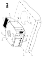
- FIG. 1 is an isometric view of a motor drive or converter system S, such as a medium voltage current-source type motor drive that receives multiphase AC input power in the range of about 2,400 to 6,900 volts and uses a rectifier to convert same to DC power supplied to a DC link and provided from the DC link to an inverter.
- the inverter switches the DC link currents to provide AC output current to a motor load with the output current being controlled by the inverter in closed loop fashion to drive the motor at a desired speed and/or torque.
- the system S includes one or more housings or enclosures E (E1,E2,E3,E4,E5) from which heat must be exhausted.
- the system S includes a parallel redundant exhaust fan system 10 formed in accordance with the present development for circulating cooling air through the enclosure E and for exhausting the resulting heated air from the enclosure E.
- the system S is shown with a parallel redundant exhaust fan system comprising nine fans 20, but only a minimum of two adjacent fans 20 are required to define the parallel redundant exhaust fan system, and the system 10 is described below using only two fans 20.
- each parallel redundant exhaust fan system 10 includes at least first and second blowers/fans 20, each of which is constructed and operated in accordance with the present development to draw air into, circulate air through, and exhaust air from an enclosure E with which the first and second fans 20 are in fluid communication.
- the first and second fans 20 of each parallel redundant fan system 10 are installed laterally or horizontally adjacent each other in a side-by-side manner at the same height on a top panel T of the enclosure E.
- the first and second adjacent fans 20 operate alternately, meaning that one fan 20 is active while the second fan is inactive or vice versa, depending upon the state of the temperature management control system of the converter system S, and the inactive fan 20 is activated automatically by the temperature management control system in case the adjacent active fan 20 (or another active fan 20 of the system 10) fails.
- the parallel adjacent arrangement of the fans 20 reduces a vertical space requirement of the enclosure E as compared to use of vertically stacked fans by minimizing the distance H that the fans extend above the enclosure top panel T which allows the converter system S to be installed in buildings and other applications where overall vertical space is limited by the roof, duct work, pipes, and/or other obstructions.
- each fan 20 includes a housing 22 that defines a hollow internal fan chamber 23 that contains an impeller system 30 comprising an impeller 32 and a motor drive system such as an electric motor 34 that selectively rotates the impeller 32 about a vertical axis 1X of rotation to draw air into and through the enclosure E and then into the fan chamber 23, where the air is exhausted through first and second exhaust outlet openings or chamber outlets 24a,24b of the chamber 23 (see also FIGS 5A and 5B ).
- an impeller system 30 comprising an impeller 32 and a motor drive system such as an electric motor 34 that selectively rotates the impeller 32 about a vertical axis 1X of rotation to draw air into and through the enclosure E and then into the fan chamber 23, where the air is exhausted through first and second exhaust outlet openings or chamber outlets 24a,24b of the chamber 23 (see also FIGS 5A and 5B ).
- the fan housing 22 further includes first and second exhaust air deflectors 25a,25b arranged in covering relation with the first and second chamber outlets 24a,24b, respectively, for receiving exhaust air flow from the chamber outlets 24a,24b and for directing the exhaust air flow from a radial horizontal path as it exits the chamber outlets 24a,24b to a upward vertical path at a deflector outlet 26, which opens to the external or ambient environment outside the fan housing 22.
- Each deflector outlet 26 is covered by a fine screen or mesh to prevent debris from entering the air deflector 25a,25b.
- the first and second chamber outlets 24a,24b have the same configuration (size/shape) and are located on opposite first and second sides of the impeller 32 at diametrically opposed locations.
- the first outlet 24a is defined by an opening in a first (front) wall W1 of the housing 22, and the second outlet 24b is defined by an opening in a second (rear) wall W2 of the housing 22.
- the front and rear housing walls W1,W2 are vertically oriented and are parallel to each other.
- the housing 22 includes parallel third and fourth walls W3,W4 arranged perpendicular or otherwise transverse to the first and second walls W1,W2.
- the first outlet 24a extends laterally across the first wall W1 from a starting location adjacent the third wall W3 a distance D1 from the third wall W3 that is at least 57% of the diameter ID of the impeller 32.
- the first outlet 24a also extends from its starting location adjacent the third wall to a location located beyond the axis of rotation IX or centerline of the impeller 32.
- the second outlet 24b extends laterally across the second wall W2 from a starting location adjacent the fourth wall W4 a distance D2 from the fourth wall W4 that is at least 57% of the diameter ID of the impeller 32.
- the second outlet 24b also extends from its starting location adjacent the fourth wall W4 to a location located beyond the axis of rotation IX or centerline of the impeller 32. As shown in FIG.
- this arrangement has been found to maximize exhaust airflow through the chamber outlets 24a,24b (indicated by arrows EF) and to minimize recirculation airflow between the impeller 32 and the first and second walls W1,W2 (indicated by arrows RF).
- the fourth wall W4 of the first fan 20 abuts or is otherwise located adjacent the third wall W3 of the second fan 20 in the parallel redundant fan system 10.
- each fan housing 22 includes first and second backflow prevention dampers 40a,40b ( FIGS. 4 , 5A , 5B ) respectively associated with and located respectively adjacent its first and second chamber outlets 24a,24b and respectively adapted to selectively open and close the first and second chamber outlets 24a,24b.
- FIG. 4 is an isometric view of one of the exhaust fans 20 with the first exhaust outlet air deflector 25a removed to reveal the first backflow prevention damper 40a (with the damper 40a in its closed position).
- FIGS. 4 is an isometric view of one of the exhaust fans 20 with the first exhaust outlet air deflector 25a removed to reveal the first backflow prevention damper 40a (with the damper 40a in its closed position).
- FIGS 5A and 5B are respective front and rear isometric views of an exhaust fan 20 formed in accordance with the present development, with both the first and second exhaust outlet air deflectors 26a,26b removed and with both the first and second backflow prevention dampers 40a,40b in their opened positions.
- the first and second dampers 40a,40b comprises respective first and second damper plates 42a,42b conformed and dimensioned to cover the respective first and second chamber outlets 24a,24b.
- the first and second damper plates 42a,42b are respectively pivotally connected to the first and second walls W1,W2 of the fan housing 22.
- the dampers 40a,40b include respective hinges 44 that pivotally connect the first and second damper plates 42 to the first and second walls W1,W2, respectively.
- the hinges 44 define horizontal pivot axes X located vertically below a lower edge 24e of the first and second chamber outlets 24a,24b.
- the first and second damper plates 42a,42b are freely pivotable about their respective horizontal pivot axes X, without spring biasing, between a closed position ( FIG. 4 ) where the first and second damper plates 42a,42b are positioned in covering relation with the first and second chamber outlets 24a,24b, respectively, and an opened position where the first and second damper plates 42a,42b are pivoted away from their respectively associated first and second chamber outlets 24a,24b in order to open the first and second chamber outlets 24a,24b ( FIGS. 5A and 5B ).
- the first and second damper plates 42a,42b block recirculating air flow into the fan chamber 23 through the respective first and second chamber outlets 24a,24b.
- the first and second damper plates 42a,42b allows exhaust air flow out of the fan chamber 23 through the respective first and second chamber outlets 24a,24b and the first and second deflectors 25a,25b.
- the first damper plate 42a includes at least one stop portion 45 that abuts the first wall W1 or other part of the fan housing 22 when the first damper plate 42a is located in its opened position to prevent further pivoting movement of the first damper plate 42a away from is closed position beyond its opened position.
- the second damper plate 42b also includes at least one stop portion 45 that abuts the second wall W2 or other part of the fan housing 22 when the second damper plate 42b is located in its opened position to prevent further pivoting movement of the second damper plate 42b away from is closed position beyond its opened position.
- the first and second dampers 40a,40b further comprise first and second counterweights 50a,50b connected to the first and second damper plates 42, respectively.
- the first and second counterweights 50a,50b exert respective first and second closing forces on the first and second damper plates 42a,42b.
- the first and second closing forces urge the first and second damper plates 42a,42b toward their closed positions.
- the first and second counterweights 50a,50b respectively hold the first and second damper plates 42a,42b in their closed positions until the fan 20 is activated and the impeller 32 induces sufficient exhaust air pressure on the first and second damper plates 42a,42b at the first and second chamber outlets 24a,24b to pivot the first and second damper plates 42a,42b from their closed positions ( FIG. 4 ) to their opened positions ( FIG. 5A and FIG. 5B ) by force of the exhaust air flow from the impeller 32.
- the first counterweight 50a comprises a first bracket 52 having a first end 52a connected to an inner face of the first damper plate 42a by fasteners or other means such as welding and a second end 52b spaced from the first end 52a and located inside the fan chamber 23.
- a first weight or ballast 52c is connected to the second end 52b of the first bracket 52, e.g., between spaced-apart arms of the first bracket as shown.
- the first bracket 52 extends from its first end 52a located adjacent the first damper plate 42a, through the first chamber outlet 24a to the second end 52b that is located inside the fan chamber 23 and to which the first ballast 52c is connected.
- the first end 52a When the first damper plate 42a is in its closed position, the first end 52a is located at a vertical level that is above the second end 52b and first ballast 52c. Also, the first ballast 52c is located at a vertical level below the horizontal pivot axis X of the first damper plate 42a when the first damper plate 42a is in its closed position.
- the second counterweight 50b has the same structure as the first counterweight 50a and thus comprises a second bracket 54 having a first end 54a connected to an inner face of the second damper plate 42b by fasteners or welding or the like and a second end 54b spaced from the first end 54a and located inside the fan chamber 23.
- a second weight or ballast 54c is connected to the second end 54b of the first bracket 54, e.g., between spaced-apart arms of the second bracket as shown.
- the second bracket 54 extends from its first end 54a located adjacent the second damper plate 42b, through the second chamber outlet 24b to the second end 54b that is located inside the fan chamber 23 and to which the second ballast 54c is connected.
- the first end 54a is located at a vertical level above the second end 54b and second ballast 54c.
- the second ballast 54c is located at a vertical level below the horizontal pivot axis X of the second damper plate 42b when the second damper plate is in its closed position.
- FIGS. 6 and 7 the above-described configuration of the first and second counterweights 50a,50b, including the shape of the first and second brackets 52,54 and location of the first and second ballast 52c,54c, ensures that the first and second counterweights 50a,50b do not contact the impeller 32 when the dampers 40a,40b move between their closed positions ( FIG. 6 ) and their opened positions ( FIG. 7 ), and also ensures that the first and second counterweights 50a,50b have a minimal effect on exhaust air flow from the fan chamber 23 through the first and second chamber outlets 24a,24b into the first and second deflectors 25a,25b (the deflectors are not shown in FIGS. 6 and 7 ).
- FIGS. 6 and 7 also show that the fan housing 22 includes an inlet I in fluid communication with the fan chamber 23 and that communicates with the interior of the enclosure E through an enclosure opening O ( FIG. 4 ).
- each damper 40a,40b of the illustrated embodiment defines a center of gravity G that is located vertically above its center of rotation as defined by its horizontal pivot axis X.
- the center of gravity G is located on only the inner side of a vertical plane including the pivot axis X, wherein the inner side of the vertical plane is the side oriented toward the inside of the fan chamber 23, i.e., the center of gravity G is located inside the cooking chamber 23 or just outside the cooking chamber between the wall W1,W2 and the vertical plane including the pivot axis X, but the center of gravity never passes through the vertical plane in which the pivot axis X is contained, even when the dampers 40a,40b are moved completely to their opened positions.
- the centers of gravity G of the respective dampers 40a,40b can be located below their respective pivot axes X, e.g., to accommodate space constraints, to purposefully direct airflow to preferred locations, to control response time of damper movements, and/or to control volume of air flow and the like.
- the first and second exhaust air deflectors 26a,26b are conformed and dimensioned to accommodate movement of the first and second damper plates 42a,42b between their opened and closed positions without interference.
- FIG. 3 shows that a space 27 exists between the periphery of the damper plates 42a,42b and the respective air deflectors 26a,26b when the damper plates 42a,42b are located in their opened positions.
- the dampers 40a,40b of an inactive fan 20 will remain closed while the fan is inactive. Exhaust air flow from adjacent active fan(s) will not enter the fan chamber 23 of the inactive fan.
- the counterweights 50a,50b hold the dampers of the inactive fan 20 closed, and negative pressure in the enclosure E will also draw the damper plates 42a,42b inward toward their closed positions to ensure that the chamber outlets 24a,24b are closed.
- the inactive fan Upon the failure or other deactivation of an active fan, the inactive fan is activated such that exhaust air pressure in the chamber 23 will force the dampers 40a,40b to their opened positions such that the exhaust air flows out of the fan chamber 23 through the chamber outlets 24a,24b and into the deflectors 25a,25b where the exhaust air is directed vertically upward through the deflector outlets 26. If the fan is again deactivated, the closing force CF of the counterweights 50a,50b will move the dampers 40a,40b back to their closed positions.
- Each fan/blower 20 is shown herein as a backward inclined motorized impeller.
- the dampers 40a,40b can alternatively be used with other types of motorized fans/blowers, and it is not intended that the present development be limited to the particular fan/blower example shown herein.
Landscapes
- Engineering & Computer Science (AREA)
- Microelectronics & Electronic Packaging (AREA)
- Physics & Mathematics (AREA)
- Thermal Sciences (AREA)
- Structures Of Non-Positive Displacement Pumps (AREA)
- Cooling Or The Like Of Electrical Apparatus (AREA)
Abstract
Description
- Motor drives are power conversion systems or "converters" that operate to provide power to electric motors in a controlled fashion to control one or more motor performance parameters, such as speed, torque, etc. Medium voltage current-source type motor drives typically receive multiphase AC input power in the voltage range of about 2,400 to 6,900 volts, which is converted in a rectifier to DC power supplied to a DC link and provided from the DC link to an inverter. The inverter switches the DC link currents to provide AC output current to a motor load with the output current being controlled by the inverter in closed loop fashion to drive the motor at a desired speed and/or torque. The rectifier is generally an active switching type rectifier that selectively activates switches to provide current from the AC input to the DC link bus to achieve AC to DC power conversion, where the rectifier gain is controlled to provide a DC link current level at the peak current level required by the motor at any given time. The inverter, in turn, implements a switching scheme to selectively connect the motor leads to the DC link bus terminals to provide motor phase currents with controlled amplitudes, phase, and frequency to implement a particular motor control strategy based on motor performance feedback values and desired performance setpoints or profiles. Voltage source drives are similar but the DC link supplies a select constant DC voltage instead of a select constant DC current.
- These motor drives generate large amounts of heat that must be exhausted from the various component housings/enclosures, e.g., from the common mode choke (CMC) housings/enclosures. This has previously been accomplished with redundant exhaust fan systems with two or more vertically stacked fans in which failure of one of the fans results in operation a redundant fan. These stacked fan systems are not suitable for use in applications where vertical space/height is limited. Also, the vertically stacked fans have been found to be suboptimal for other reasons such as noise, efficiency, and other reasons.
- In accordance with a first aspect of the present development, an electrical equipment enclosure includes an enclosure housing and a parallel redundant fan system including at least first and second fans supported on the enclosure housing. The first and second fans are located adjacent each other and each include: (i) a fan housing defining a fan chamber in which an impeller is supported for rotation about an axis of rotation; (ii) a first chamber outlet in communication with the fan chamber and defined by an opening in a first wall of the fan housing; (iii) a second chamber outlet in communication with the fan chamber and defined by an opening in a second wall of the fan housing; and, (iii) first and second backflow prevention dampers respectively associated with the first and second chamber outlets. The first backflow prevention damper includes: (i) a first damper plate located outside the fan chamber and pivotally connected to the first wall of the fan housing, the first damper plate pivotable about a first pivot axis between a closed position where it is positioned in covering relation with the first chamber outlet and an opened position where it is pivoted away from the first chamber outlet to allow exhaust air flow through the first chamber outlet from the fan chamber; and (ii) a first counterweight connected to the first damper plate that exerts a closing force on the first damper plate that urges the first damper plate toward its closed position. The second backflow prevention damper includes: (i) a second damper plate located outside the fan chamber and pivotally connected to the second wall of the fan housing, the second damper plate pivotable about a second pivot axis between a closed position where it is positioned in covering relation with the second chamber outlet and an opened position where it is pivoted away from the second chamber outlet to allow exhaust air flow through the second chamber outlet from the fan chamber; and (ii) a second counterweight connected to the second damper plate that exerts a closing force on the second damper plate that urges the second damper plate toward its closed position. The first and second damper plates selectively pivot from their closed positions toward their opened positions against the closing force of the first and second counterweights, respectively, in response to exhaust air flow pressure exerted on the first and second damper plates by exhaust air flowing from the fan chamber through the first and second chamber outlets.
- In accordance with another aspect of the present development, a parallel redundant fan system includes at least first and second fans located adjacent each other. Each fan includes: (i) a fan housing defining a fan chamber in which an impeller is supported for rotation about an axis of rotation; (ii) a first chamber outlet in communication with the fan chamber and defined by an opening in a first wall of the fan housing; (iii) a second chamber outlet in communication with the fan chamber and defined by an opening in a second wall of the fan housing; and, (iii) first and second backflow prevention dampers respectively associated with the first and second chamber outlets. The first backflow prevention damper includes: (i) a first damper plate located outside the fan chamber and pivotally connected to the first wall of the fan housing, the first damper plate pivotable about a first pivot axis between a closed position where it is positioned in covering relation with the first chamber outlet and an opened position where it is pivoted away from the first chamber outlet to allow exhaust air flow through the first chamber outlet from the fan chamber; and (ii) a first counterweight connected to the first damper plate that exerts a closing force on the first damper plate that urges the first damper plate toward its closed position. The second backflow prevention damper includes: (i) a second damper plate located outside the fan chamber and pivotally connected to the second wall of the fan housing, the second damper plate pivotable about a second pivot axis between a closed position where it is positioned in covering relation with the second chamber outlet and an opened position where it is pivoted away from the second chamber outlet to allow exhaust air flow through the second chamber outlet from the fan chamber; and (ii) a second counterweight connected to the second damper plate that exerts a closing force on the second damper plate that urges the second damper plate toward its closed position. The first and second damper plates selectively pivot from their closed positions toward their opened positions against the closing force of the first and second counterweights, respectively, in response to exhaust air flow pressure exerted on the first and second damper plates by exhaust air flowing from the fan chamber through the first and second chamber outlets.
-
-
FIG. 1 is an isometric view of a drive or converter system including a plurality of individual cabinets which enclose common mode choke (CMC) magnetics, power semiconductors, capacitors, line reactors, and various other electrical components and a parallel redundant exhaust fan system formed in accordance with the present development; -
FIG. 2 is a partial enlarged isometric view of one of the CMC enclosures ofFIG. 1 , showing a two fan parallel redundant exhaust fan system including first and second exhaust fans each formed in accordance with the present development; -
FIG. 3 is a top view of an exhaust fan formed in accordance with the present development, with portions removed, showing the exhaust air flow. -
FIG. 4 is an isometric view of one of the exhaust fans ofFIG. 2 , with an exhaust outlet air deflector removed to reveal a backflow prevention damper provided in accordance with the present development (with the damper in its closed position); -
FIGS. 5A and5B are respective front and rear isometric views of an exhaust fan formed in accordance with the present development, with both exhaust outlet air deflectors removed and with both backflow prevention dampers in their opened positions; -
FIG. 6 is a side view of the exhaust fan ofFIG. 4 (with both exhaust air deflectors removed) and showing the backflow prevention dampers in their closed positions; -
FIG. 7 is a side view of the exhaust fan similar toFIG. 6 , but strowing both backflow prevention dampers in their opened positions; -
FIG. 8 is a diagram that illustrates the structure and operation of a backflow prevention damper formed in accordance with the present development. -
FIG. 1 is an isometric view of a motor drive or converter system S, such as a medium voltage current-source type motor drive that receives multiphase AC input power in the range of about 2,400 to 6,900 volts and uses a rectifier to convert same to DC power supplied to a DC link and provided from the DC link to an inverter. The inverter switches the DC link currents to provide AC output current to a motor load with the output current being controlled by the inverter in closed loop fashion to drive the motor at a desired speed and/or torque. The system S includes one or more housings or enclosures E (E1,E2,E3,E4,E5) from which heat must be exhausted. According to the present development, the system S includes a parallel redundantexhaust fan system 10 formed in accordance with the present development for circulating cooling air through the enclosure E and for exhausting the resulting heated air from the enclosure E. The system S is shown with a parallel redundant exhaust fan system comprising ninefans 20, but only a minimum of twoadjacent fans 20 are required to define the parallel redundant exhaust fan system, and thesystem 10 is described below using only twofans 20. - Referring now to
FIG. 2 , each parallel redundantexhaust fan system 10 includes at least first and second blowers/fans 20, each of which is constructed and operated in accordance with the present development to draw air into, circulate air through, and exhaust air from an enclosure E with which the first andsecond fans 20 are in fluid communication. The first andsecond fans 20 of each parallelredundant fan system 10 are installed laterally or horizontally adjacent each other in a side-by-side manner at the same height on a top panel T of the enclosure E. The first and secondadjacent fans 20 operate alternately, meaning that onefan 20 is active while the second fan is inactive or vice versa, depending upon the state of the temperature management control system of the converter system S, and theinactive fan 20 is activated automatically by the temperature management control system in case the adjacent active fan 20 (or anotheractive fan 20 of the system 10) fails. The parallel adjacent arrangement of thefans 20 reduces a vertical space requirement of the enclosure E as compared to use of vertically stacked fans by minimizing the distance H that the fans extend above the enclosure top panel T which allows the converter system S to be installed in buildings and other applications where overall vertical space is limited by the roof, duct work, pipes, and/or other obstructions. - Referring also to
FIG. 3 , eachfan 20 includes ahousing 22 that defines a hollowinternal fan chamber 23 that contains animpeller system 30 comprising animpeller 32 and a motor drive system such as anelectric motor 34 that selectively rotates theimpeller 32 about a vertical axis 1X of rotation to draw air into and through the enclosure E and then into thefan chamber 23, where the air is exhausted through first and second exhaust outlet openings orchamber outlets 24a,24b of the chamber 23 (see alsoFIGS 5A and5B ). Thefan housing 22 further includes first and secondexhaust air deflectors 25a,25b arranged in covering relation with the first andsecond chamber outlets 24a,24b, respectively, for receiving exhaust air flow from thechamber outlets 24a,24b and for directing the exhaust air flow from a radial horizontal path as it exits thechamber outlets 24a,24b to a upward vertical path at adeflector outlet 26, which opens to the external or ambient environment outside thefan housing 22. Eachdeflector outlet 26 is covered by a fine screen or mesh to prevent debris from entering theair deflector 25a,25b. - With continuing reference to
FIGS. 3 ,5A , and5B , the first andsecond chamber outlets 24a,24b have the same configuration (size/shape) and are located on opposite first and second sides of theimpeller 32 at diametrically opposed locations. Thefirst outlet 24a is defined by an opening in a first (front) wall W1 of thehousing 22, and the second outlet 24b is defined by an opening in a second (rear) wall W2 of thehousing 22. The front and rear housing walls W1,W2 are vertically oriented and are parallel to each other. Thehousing 22 includes parallel third and fourth walls W3,W4 arranged perpendicular or otherwise transverse to the first and second walls W1,W2. Thefirst outlet 24a extends laterally across the first wall W1 from a starting location adjacent the third wall W3 a distance D1 from the third wall W3 that is at least 57% of the diameter ID of theimpeller 32. Thefirst outlet 24a also extends from its starting location adjacent the third wall to a location located beyond the axis of rotation IX or centerline of theimpeller 32. The second outlet 24b extends laterally across the second wall W2 from a starting location adjacent the fourth wall W4 a distance D2 from the fourth wall W4 that is at least 57% of the diameter ID of theimpeller 32. The second outlet 24b also extends from its starting location adjacent the fourth wall W4 to a location located beyond the axis of rotation IX or centerline of theimpeller 32. As shown inFIG. 3 , this arrangement has been found to maximize exhaust airflow through thechamber outlets 24a,24b (indicated by arrows EF) and to minimize recirculation airflow between theimpeller 32 and the first and second walls W1,W2 (indicated by arrows RF). The fourth wall W4 of thefirst fan 20 abuts or is otherwise located adjacent the third wall W3 of thesecond fan 20 in the parallelredundant fan system 10. - When one of the
fans 20 is active and the other is inactive and available as a redundant backup as described above, it is highly undesirable and inefficient to allow recirculatory exhaust airflow from theactive fan 20 to be drawn into theinactive fan housing 22 through theair deflectors 25a,25b andchamber outlets 24a,24b and into thefan chamber 23 of theinactive fan 22. The upward vertical orientation of thedeflector outlets 26 helps to discourage this undesired recirculating exhaust airflow. However, the negative air pressure inside the enclosure E due to operation of theactive fan 20 will tend to draw the exhaust airflow from theoutlets 26 of the activefan air deflectors 25a,25b into thefan chamber 23 of theinactive fan 20 through itsair deflectors 25a,25b and into the enclosure E. - To prevent this undesired recirculating exhaust airflow, each
fan housing 22 includes first and secondbackflow prevention dampers FIGS. 4 ,5A ,5B ) respectively associated with and located respectively adjacent its first andsecond chamber outlets 24a,24b and respectively adapted to selectively open and close the first andsecond chamber outlets 24a,24b.FIG. 4 is an isometric view of one of theexhaust fans 20 with the first exhaustoutlet air deflector 25a removed to reveal the firstbackflow prevention damper 40a (with thedamper 40a in its closed position).FIGS. 5A and5B are respective front and rear isometric views of anexhaust fan 20 formed in accordance with the present development, with both the first and second exhaust outlet air deflectors 26a,26b removed and with both the first and secondbackflow prevention dampers second dampers second damper plates second chamber outlets 24a,24b. The first andsecond damper plates fan housing 22. In particular, thedampers respective hinges 44 that pivotally connect the first and second damper plates 42 to the first and second walls W1,W2, respectively. Thehinges 44 define horizontal pivot axes X located vertically below alower edge 24e of the first andsecond chamber outlets 24a,24b. - The first and
second damper plates FIG. 4 ) where the first andsecond damper plates second chamber outlets 24a,24b, respectively, and an opened position where the first andsecond damper plates second chamber outlets 24a,24b in order to open the first andsecond chamber outlets 24a,24b (FIGS. 5A and5B ). In their closed positions, the first andsecond damper plates fan chamber 23 through the respective first andsecond chamber outlets 24a,24b. In their opened positions, the first andsecond damper plates fan chamber 23 through the respective first andsecond chamber outlets 24a,24b and the first andsecond deflectors 25a,25b. - The
first damper plate 42a includes at least onestop portion 45 that abuts the first wall W1 or other part of thefan housing 22 when thefirst damper plate 42a is located in its opened position to prevent further pivoting movement of thefirst damper plate 42a away from is closed position beyond its opened position. Likewise, thesecond damper plate 42b also includes at least onestop portion 45 that abuts the second wall W2 or other part of thefan housing 22 when thesecond damper plate 42b is located in its opened position to prevent further pivoting movement of thesecond damper plate 42b away from is closed position beyond its opened position. - The first and
second dampers second counterweights 50a,50b connected to the first and second damper plates 42, respectively. The first andsecond counterweights 50a,50b exert respective first and second closing forces on the first andsecond damper plates second damper plates second counterweights 50a,50b respectively hold the first andsecond damper plates fan 20 is activated and theimpeller 32 induces sufficient exhaust air pressure on the first andsecond damper plates second chamber outlets 24a,24b to pivot the first andsecond damper plates FIG. 4 ) to their opened positions (FIG. 5A andFIG. 5B ) by force of the exhaust air flow from theimpeller 32. - The first counterweight 50a comprises a
first bracket 52 having afirst end 52a connected to an inner face of thefirst damper plate 42a by fasteners or other means such as welding and a second end 52b spaced from thefirst end 52a and located inside thefan chamber 23. A first weight orballast 52c is connected to the second end 52b of thefirst bracket 52, e.g., between spaced-apart arms of the first bracket as shown. Thefirst bracket 52 extends from itsfirst end 52a located adjacent thefirst damper plate 42a, through thefirst chamber outlet 24a to the second end 52b that is located inside thefan chamber 23 and to which thefirst ballast 52c is connected. When thefirst damper plate 42a is in its closed position, thefirst end 52a is located at a vertical level that is above the second end 52b andfirst ballast 52c. Also, thefirst ballast 52c is located at a vertical level below the horizontal pivot axis X of thefirst damper plate 42a when thefirst damper plate 42a is in its closed position. - The
second counterweight 50b has the same structure as the first counterweight 50a and thus comprises asecond bracket 54 having afirst end 54a connected to an inner face of thesecond damper plate 42b by fasteners or welding or the like and a second end 54b spaced from thefirst end 54a and located inside thefan chamber 23. A second weight or ballast 54c is connected to the second end 54b of thefirst bracket 54, e.g., between spaced-apart arms of the second bracket as shown. Thesecond bracket 54 extends from itsfirst end 54a located adjacent thesecond damper plate 42b, through the second chamber outlet 24b to the second end 54b that is located inside thefan chamber 23 and to which the second ballast 54c is connected. When thesecond damper plate 42b is in its closed position, thefirst end 54a is located at a vertical level above the second end 54b and second ballast 54c. The second ballast 54c is located at a vertical level below the horizontal pivot axis X of thesecond damper plate 42b when the second damper plate is in its closed position. - As shown in
FIGS. 6 and7 , the above-described configuration of the first andsecond counterweights 50a,50b, including the shape of the first andsecond brackets second ballast 52c,54c, ensures that the first andsecond counterweights 50a,50b do not contact theimpeller 32 when thedampers FIG. 6 ) and their opened positions (FIG. 7 ), and also ensures that the first andsecond counterweights 50a,50b have a minimal effect on exhaust air flow from thefan chamber 23 through the first andsecond chamber outlets 24a,24b into the first andsecond deflectors 25a,25b (the deflectors are not shown inFIGS. 6 and7 ).FIGS. 6 and7 also show that thefan housing 22 includes an inlet I in fluid communication with thefan chamber 23 and that communicates with the interior of the enclosure E through an enclosure opening O (FIG. 4 ). - Referring to
FIG. 8 , it can be seen that eachdamper damper plates fan chamber 23, i.e., the center of gravity G is located inside thecooking chamber 23 or just outside the cooking chamber between the wall W1,W2 and the vertical plane including the pivot axis X, but the center of gravity never passes through the vertical plane in which the pivot axis X is contained, even when thedampers second counterweights 50a,50b will always establish the above-noted closing force (indicated by the arrow CF) that is required to urge the first andsecond damper plates respective dampers - The first and second exhaust air deflectors 26a,26b are conformed and dimensioned to accommodate movement of the first and
second damper plates FIG. 3 shows that aspace 27 exists between the periphery of thedamper plates damper plates - In use, the
dampers inactive fan 20 will remain closed while the fan is inactive. Exhaust air flow from adjacent active fan(s) will not enter thefan chamber 23 of the inactive fan. Thecounterweights 50a,50b hold the dampers of theinactive fan 20 closed, and negative pressure in the enclosure E will also draw thedamper plates chamber outlets 24a,24b are closed. Upon the failure or other deactivation of an active fan, the inactive fan is activated such that exhaust air pressure in thechamber 23 will force thedampers fan chamber 23 through thechamber outlets 24a,24b and into thedeflectors 25a,25b where the exhaust air is directed vertically upward through thedeflector outlets 26. If the fan is again deactivated, the closing force CF of thecounterweights 50a,50b will move thedampers - Each fan/
blower 20 is shown herein as a backward inclined motorized impeller. Thedampers - The development has been described with reference to preferred embodiments. Those of ordinary skill in the art will recognize that modifications and alterations to the preferred embodiments are possible. The disclosed preferred embodiments are not intended to limit the scope of the following claims, which are to be construed as broadly as possible, whether literally or according to the doctrine of equivalents.
-
- Embodiment 1: An electrical equipment enclosure comprising:
- an enclosure housing;
- a parallel redundant fan system comprising at least first and second fans supported on said enclosure housing, said first and second fans located adjacent each other and each comprising: (i) a fan housing defining a fan chamber in which an impeller is supported for rotation about an axis of rotation; (ii) a first chamber outlet in communication with said fan chamber and defined by an opening in a first wall of said fan housing; (iii) a second chamber outlet in communication with said fan chamber and defined by an opening in a second wall of said fan housing; (iii) first and second backflow prevention dampers respectively associated with said first and second chamber outlets;
- said first backflow prevention damper comprising: (i) a first damper plate located outside said fan chamber and pivotally connected to said first wall of said fan housing, said first damper plate pivotable about a first pivot axis between a closed position where it is positioned in covering relation with said first chamber outlet and an opened position where it is pivoted away from said first chamber outlet to allow exhaust air flow through said first chamber outlet from said fan chamber; and (ii) a first counterweight connected to said first damper plate that exerts a closing force on said first damper plate that urges said first damper plate toward its closed position;
- said second backflow prevention damper comprising: (i) a second damper plate located outside said fan chamber and pivotally connected to said second wall of said fan housing, said second damper plate pivotable about a second pivot axis between a closed position where it is positioned in covering relation with said second chamber outlet and an opened position where it is pivoted away from said second chamber outlet to allow exhaust air flow through said second chamber outlet from said fan chamber; and (ii) a second counterweight connected to said second damper plate that exerts a closing force on said second damper plate that urges said second damper plate toward its closed position;
- wherein said first and second damper plates selectively pivot from their closed positions toward their opened positions against the closing force of the first and second counterweights, respectively, in response to exhaust air flow pressure exerted on the first and second damper plates by exhaust air flowing from said fan chamber through said first and second chamber outlets.
- Embodiment 2: The electrical equipment enclosure as set forth in
embodiment 1, wherein:- said first counterweight comprises a first bracket that is connected to said first damper plate, and a first ballast that is connected to the first bracket at a location spaced from an inside face of said first damper plate; and,
- said second counterweight comprises a second bracket that is connected to said second damper plate, and a second ballast that is connected to the second bracket at a location spaced from an inside face of said second damper plate.
- Embodiment 3: The electrical equipment enclosure as set forth in embodiment 2, wherein:
- said first bracket extends from said inside face of said first damper plate through said first chamber outlet and said first ballast is located inside said fan chamber; and,
- said second bracket extends from said inside face of said second damper plate through said second chamber outlet and said second ballast is located inside said fan chamber.
- Embodiment 4: The electrical equipment enclosure as set forth in embodiment 3, wherein:
- said first and second damper plates pivot about respective first and second horizontal pivot axes;
- said first and second backflow prevention dampers define respective centers of gravity that are located vertically above said first and second pivot axes and that are located horizontally between said impeller and first and second vertical planes that respectively include said first and second pivot axes.
- Embodiment 5: The electrical equipment enclosure as set forth in embodiment 4, wherein:
- a first end of said first bracket connected to said first damper plate is located at a vertical level above a second end of said first bracket to which said first ballast is connected and above said first ballast when said first damper plate is located in its closed position;
- a first end of said second bracket connected to said second damper plate is located at a vertical level above a second end of said second bracket to which said second ballast is connected and above said second ballast when said second damper plate is located in its closed position.
- Embodiment 6: The electrical equipment enclosure as set forth in embodiment 5, wherein said first and second ballasts are located vertically below said first and second horizontal pivot axes when said first and second damper plates are in their respective closed positions.
- Embodiment 7: The electrical equipment enclosure as set forth in
embodiment 1, wherein:- said first damper plates comprise respective stops;
- said stop of said first damper plate abuts said first wall of said fan housing and prevents pivoting movement of said first damper plate away from its closed position beyond its opened position when said first damper plate is located in its opened position;
- said stop of said second damper plate abuts said second wall of said fan chamber housing and prevents pivoting movement of said second damper plate away from its closed position beyond its opened position when said second damper plate is located in its opened position.
- Embodiment 8: The electrical equipment enclosure as set forth in
embodiment 1, wherein:- said first and second walls of said fan housing are vertically oriented and are parallel and spaced-apart relative to each other; and,
- said first and second chamber outlets are located on opposite sides of said impeller.
- Embodiment 9: The electrical equipment enclosure as set forth in embodiment 8, wherein:
- said fan housing further comprises third and fourth spaced-apart walls that are arranged transverse to said first and second walls;
- said first chamber outlet extends laterally across the first wall from a location adjacent the third wall a first distance from the third wall that is greater than a minimum distance between the third wall and the axis of rotation of the impeller;
- said second chamber outlet extends laterally across the second wall from a location adjacent the fourth wall a second distance that is greater than a minimum distance between the fourth wall and the axis of rotation of the impeller.
- Embodiment 10: The electrical equipment enclosure as set forth in embodiment 9, wherein said first distance is at least 57% of a diameter of the impeller, and said second distance is at least 57% of the diameter of the impeller.
- Embodiment 11: The electrical equipment enclosure as set forth in
embodiment 10, further comprising:- first and second exhaust air deflectors arranged in covering relation with the first and second chamber outlets, respectively, for receiving exhaust air flow from the first and second chamber outlets and for directing the exhaust air flow from a radial horizontal path as it exits the first and second chamber outlets to a upward vertical path, each of said first and second exhaust air deflectors including an upwardly opening deflector outlet that opens to an ambient environment outside said fan chamber.
- Embodiment 12: A parallel redundant fan system comprising:
- at least first and second fans located adjacent each other and each comprising: (i) a fan housing defining a fan chamber in which an impeller is support for rotation; (ii) a first chamber outlet in communication with said fan chamber and defined by an opening in a first wall of said fan housing; (iii) a second chamber outlet in communication with said fan chamber and defined by an opening in a second wall of said fan housing; (iii) first and second backflow prevention dampers respectively associated with said first and second chamber outlets;
- said first backflow prevention damper comprising: (i) a first damper plate located outside said fan chamber and pivotally connected to said first wall of said fan housing, said first damper plate pivotable about a first pivot axis between a closed position where it is positioned in covering relation with said first chamber outlet and an opened position where it is pivoted away from said first chamber outlet to allow exhaust air flow through said first chamber outlet from said fan chamber; and (ii) a first counterweight connected to said first damper plate that exerts a closing force on said first damper plate that urges said first damper plate toward its closed position;
- said second backflow prevention damper comprising: (i) a second damper plate located outside said fan chamber and pivotally connected to said second wall of said fan housing, said second damper plate pivotable about a second pivot axis between a closed position where it is positioned in covering relation with said second chamber outlet and an opened position where it is pivoted away from said second chamber outlet to allow exhaust air flow through said second chamber outlet from said fan chamber; and (ii) a second counterweight connected to said second damper plate that exerts a closing force on said second damper plate that urges said second damper plate toward its closed position;
- wherein said first and second damper plates selectively pivot from their closed positions toward their opened positions against the closing force of the first and second counterweights, respectively, in response to exhaust air flow pressure exerted on the first and second damper plates by exhaust air flowing from said fan chamber through said first and second chamber outlets.
- Embodiment 13: The fan system as set forth in
embodiment 12, wherein:- said first counterweight comprises a first bracket that is connected to said first damper plate, and a first ballast that is connected to the first bracket at a location spaced from an inside face of said first damper plate; and,
- said second counterweight comprises a second bracket that is connected to said second damper plate, and a second ballast that is connected to the second bracket at a location spaced from an inside face of said second damper plate.
- Embodiment 14: The fan system as set forth in embodiment 13, wherein:
- said first bracket extends from said inside face of said first damper plate through said first chamber outlet and said first ballast is located inside said fan chamber; and,
- said second bracket extends from said inside face of said second damper plate through said second chamber outlet and said second ballast is located inside said fan chamber.
- Embodiment 15: The fan system as set forth in embodiment 14, wherein:
- said first and second damper plates pivot about respective first and second horizontal pivot axes;
- said first and second backflow prevention dampers define respective centers of gravity that are located vertically above said first and second pivot axes and that are located horizontally between said impeller and first and second vertical planes that respectively include said first and second pivot axes.
- Embodiment 16: The fan system as set forth in embodiment 15, wherein:
- a first end of said first bracket connected to said first damper plate is located at a vertical level above a second end of said first bracket to which said first ballast is connected and above said first ballast when said first damper plate is located in its closed position;
- a first end of said second bracket connected to said second damper plate is located at a vertical level above a second end of said second bracket to which said second ballast is connected and above said second ballast when said second damper plate is located in its closed position.
- Embodiment 17: The fan system as set forth in embodiment 16, wherein said first and second ballasts are located vertically below said first and second horizontal pivot axes when said first and second damper plates are in their respective closed positions.
- Embodiment 18: The fan system as set forth in
embodiment 12, wherein:- said first damper plates comprise respective stops;
- said stop of said first damper plate abuts said first wall of said fan housing and prevents pivoting movement of said first damper plate away from its closed position beyond its opened position when said first damper plate is located in its opened position;
- said stop of said second damper plate abuts said second wall of said fan chamber housing and prevents pivoting movement of said second damper plate away from its closed position beyond its opened position when said second damper plate is located in its opened position.
- Embodiment 19: The fan system as set forth in
embodiment 12, wherein:- said first and second walls of said fan housing are vertically oriented and are parallel and spaced-apart relative to each other; and,
- said first and second chamber outlets are located on opposite sides of said impeller.
- Embodiment 20: The fan system as set forth in embodiment 19, wherein:
- said fan housing further comprises third and fourth spaced-apart walls that are arranged transverse to said first and second walls;
- said first chamber outlet extends laterally across the first wall from a location adjacent the third wall a first distance from the third wall that is greater than a minimum distance between the third wall and the axis of rotation of the impeller;
- said second chamber outlet extends laterally across the second wall from a location adjacent the fourth wall a second distance that is greater than a minimum distance between the fourth wall and the axis of rotation of the impeller.
- Embodiment 21: The fan system as set forth in
embodiment 20, further comprising:- first and second exhaust air deflectors arranged in covering relation with the first and second chamber outlets, respectively, for receiving exhaust air flow from the first and second chamber outlets and for directing the exhaust air flow from a radial horizontal path as it exits the first and second chamber outlets to a upward vertical path, each of said first and second exhaust air deflectors including an upwardly opening deflector outlet that opens to an ambient environment outside said fan chamber.
- Embodiment 22: The fan system as set forth in embodiment 19, wherein:
- said fan housing further comprises third and fourth spaced-apart walls that are arranged transverse to said first and second walls;
- said first chamber outlet extends laterally across the first wall from a location adjacent the third wall a first distance from the third wall that is greater than a minimum distance between the third wall and the axis of rotation of the impeller;
- said second chamber outlet extends laterally across the second wall from a location adjacent the fourth wall a second distance that is greater than a minimum distance between the fourth wall and the axis of rotation of the impeller;
- said first distance is at least 57% of a diameter of the impeller; and,
- said second distance is at least 57% of the diameter of the impeller.
Claims (15)
- An electrical equipment enclosure comprising:an enclosure housing;a parallel redundant fan system comprising at least first and second fans supported on said enclosure housing, said first and second fans located adjacent each other and each comprising: (i) a fan housing defining a fan chamber in which an impeller is supported for rotation about an axis of rotation; (ii) a first chamber outlet in communication with said fan chamber and defined by an opening in a first wall of said fan housing; (iii) a second chamber outlet in communication with said fan chamber and defined by an opening in a second wall of said fan housing; (iii) first and second backflow prevention dampers respectively associated with said first and second chamber outlets;said first backflow prevention damper comprising: (i) a first damper plate located outside said fan chamber and pivotally connected to said first wall of said fan housing, said first damper plate pivotable about a first pivot axis between a closed position where it is positioned in covering relation with said first chamber outlet and an opened position where it is pivoted away from said first chamber outlet to allow exhaust air flow through said first chamber outlet from said fan chamber; and (ii) a first counterweight connected to said first damper plate that exerts a closing force on said first damper plate that urges said first damper plate toward its closed position;said second backflow prevention damper comprising: (i) a second damper plate located outside said fan chamber and pivotally connected to said second wall of said fan housing, said second damper plate pivotable about a second pivot axis between a closed position where it is positioned in covering relation with said second chamber outlet and an opened position where it is pivoted away from said second chamber outlet to allow exhaust air flow through said second chamber outlet from said fan chamber; and (ii) a second counterweight connected to said second damper plate that exerts a closing force on said second damper plate that urges said second damper plate toward its closed position;wherein said first and second damper plates selectively pivot from their closed positions toward their opened positions against the closing force of the first and second counterweights, respectively, in response to exhaust air flow pressure exerted on the first and second damper plates by exhaust air flowing from said fan chamber through said first and second chamber outlets.
- The electrical equipment enclosure as set forth in claim 1, wherein:said first counterweight comprises a first bracket that is connected to said first damper plate, and a first ballast that is connected to the first bracket at a location spaced from an inside face of said first damper plate; and,said second counterweight comprises a second bracket that is connected to said second damper plate, and a second ballast that is connected to the second bracket at a location spaced from an inside face of said second damper plate.
- The electrical equipment enclosure as set forth in claim 2, wherein:said first bracket extends from said inside face of said first damper plate through said first chamber outlet and said first ballast is located inside said fan chamber; and,said second bracket extends from said inside face of said second damper plate through said second chamber outlet and said second ballast is located inside said fan chamber, and/orwherein:said first and second damper plates pivot about respective first and second horizontal pivot axes;said first and second backflow prevention dampers define respective centers of gravity that are located vertically above said first and second pivot axes and that are located horizontally between said impeller and first and second vertical planes that respectively include said first and second pivot axes.
- The electrical equipment enclosure as set forth in claim 3, wherein:a first end of said first bracket connected to said first damper plate is located at a vertical level above a second end of said first bracket to which said first ballast is connected and above said first ballast when said first damper plate is located in its closed position;a first end of said second bracket connected to said second damper plate is located at a vertical level above a second end of said second bracket to which said second ballast is connected and above said second ballast when said second damper plate is located in its closed position, and/orwherein said first and second ballasts are located vertically below said first and second horizontal pivot axes when said first and second damper plates are in their respective closed positions.
- The electrical equipment enclosure as set forth in any one of claims 1 to 4, wherein:said first damper plates comprise respective stops;said stop of said first damper plate abuts said first wall of said fan housing and prevents pivoting movement of said first damper plate away from its closed position beyond its opened position when said first damper plate is located in its opened position;said stop of said second damper plate abuts said second wall of said fan chamber housing and prevents pivoting movement of said second damper plate away from its closed position beyond its opened position when said second damper plate is located in its opened position.
- The electrical equipment enclosure as set forth in any one of claims 1 to 5, wherein:said first and second walls of said fan housing are vertically oriented and are parallel and spaced-apart relative to each other; andsaid first and second chamber outlets are located on opposite sides of said impeller, and/orwherein:said fan housing further comprises third and fourth spaced-apart walls that are arranged transverse to said first and second walls;said first chamber outlet extends laterally across the first wall from a location adjacent the third wall a first distance from the third wall that is greater than a minimum distance between the third wall and the axis of rotation of the impeller;said second chamber outlet extends laterally across the second wall from a location adjacent the fourth wall a second distance that is greater than a minimum distance between the fourth wall and the axis of rotation of the impeller.
- The electrical equipment enclosure as set forth in claim 6, wherein said first distance is at least 57% of a diameter of the impeller, and said second distance is at least 57% of the diameter of the impeller, and/or
further comprising:first and second exhaust air deflectors arranged in covering relation with the first andsecond chamber outlets, respectively, for receiving exhaust air flow from the first and second chamber outlets and for directing the exhaust air flow from a radial horizontal path as it exits the first and second chamber outlets to a upward vertical path, each of said first and second exhaust air deflectors including an upwardly opening deflector outlet that opens to an ambient environment outside said fan chamber. - A parallel redundant fan system comprising:at least first and second fans located adjacent each other and each comprising: (i) a fan housing defining a fan chamber in which an impeller is support for rotation; (ii) a first chamber outlet in communication with said fan chamber and defined by an opening in a first wall of said fan housing; (iii) a second chamber outlet in communication with said fan chamber and defined by an opening in a second wall of said fan housing; (iii) first and second backflow prevention dampers respectively associated with said first and second chamber outlets;said first backflow prevention damper comprising: (i) a first damper plate located outside said fan chamber and pivotally connected to said first wall of said fan housing, said first damper plate pivotable about a first pivot axis between a closed position where it is positioned in covering relation with said first chamber outlet and an opened position where it is pivoted away from said first chamber outlet to allow exhaust air flow through said first chamber outlet from said fan chamber; and (ii) a first counterweight connected to said first damper plate that exerts a closing force on said first damper plate that urges said first damper plate toward its closed position;said second backflow prevention damper comprising: (i) a second damper plate located outside said fan chamber and pivotally connected to said second wall of said fan housing, said second damper plate pivotable about a second pivot axis between a closed position where it is positioned in covering relation with said second chamber outlet and an opened position where it is pivoted away from said second chamber outlet to allow exhaust air flow through said second chamber outlet from said fan chamber; and (ii) a second counterweight connected to said second damper plate that exerts a closing force on said second damper plate that urges said second damper plate toward its closed position;wherein said first and second damper plates selectively pivot from their closed positions toward their opened positions against the closing force of the first and second counterweights, respectively, in response to exhaust air flow pressure exerted on the first and second damper plates by exhaust air flowing from said fan chamber through said first and second chamber outlets.
- The fan system as set forth in claim 8, wherein:said first counterweight comprises a first bracket that is connected to said first damper plate, and a first ballast that is connected to the first bracket at a location spaced from an inside face of said first damper plate; and,said second counterweight comprises a second bracket that is connected to said second damper plate, and a second ballast that is connected to the second bracket at a location spaced from an inside face of said second damper plate, and/orwherein:said first bracket extends from said inside face of said first damper plate through said first chamber outlet and said first ballast is located inside said fan chamber; and,said second bracket extends from said inside face of said second damper plate through said second chamber outlet and said second ballast is located inside said fan chamber.
- The fan system as set forth in claim 9, wherein:said first and second damper plates pivot about respective first and second horizontal pivot axes;said first and second backflow prevention dampers define respective centers of gravity that are located vertically above said first and second pivot axes and that are located horizontally between said impeller and first and second vertical planes that respectively include said first and second pivot axes.
- The fan system as set forth in claim 10, wherein:a first end of said first bracket connected to said first damper plate is located at a vertical level above a second end of said first bracket to which said first ballast is connected and above said first ballast when said first damper plate is located in its closed position;a first end of said second bracket connected to said second damper plate is located at a vertical level above a second end of said second bracket to which said second ballast is connected and above said second ballast when said second damper plate is located in its closed position.
- The fan system as set forth in claim 11, wherein said first and second ballasts are located vertically below said first and second horizontal pivot axes when said first and second damper plates are in their respective closed positions.
- The fan system as set forth in claim 10, wherein:said first damper plates comprise respective stops;said stop of said first damper plate abuts said first wall of said fan housing and prevents pivoting movement of said first damper plate away from its closed position beyond its opened position when said first damper plate is located in its opened position;said stop of said second damper plate abuts said second wall of said fan chamber housing and prevents pivoting movement of said second damper plate away from its closed position beyond its opened position when said second damper plate is located in its opened position.
- The fan system as set forth in claim 10, wherein:said first and second walls of said fan housing are vertically oriented and are parallel and spaced-apart relative to each other; and,said first and second chamber outlets are located on opposite sides of said impeller, and/orwherein:said fan housing further comprises third and fourth spaced-apart walls that are arranged transverse to said first and second walls;said first chamber outlet extends laterally across the first wall from a location adjacent the third wall a first distance from the third wall that is greater than a minimum distance between the third wall and the axis of rotation of the impeller;said second chamber outlet extends laterally across the second wall from a location adjacent the fourth wall a second distance that is greater than a minimum distance between the fourth wall and the axis of rotation of the impeller, and/orfurther comprising:first and second exhaust air deflectors arranged in covering relation with the first andsecond chamber outlets, respectively, for receiving exhaust air flow from the first and second chamber outlets and for directing the exhaust air flow from a radial horizontal path as it exits the first and second chamber outlets to a upward vertical path, each of said first and second exhaust air deflectors including an upwardly opening deflector outlet that opens to an ambient environment outside said fan chamber.
- The fan system as set forth in claim 14, wherein:said fan housing further comprises third and fourth spaced-apart walls that are arranged transverse to said first and second walls;said first chamber outlet extends laterally across the first wall from a location adjacent the third wall a first distance from the third wall that is greater than a minimum distance between the third wall and the axis of rotation of the impeller;said second chamber outlet extends laterally across the second wall from a location adjacent the fourth wall a second distance that is greater than a minimum distance between the fourth wall and the axis of rotation of the impeller;said first distance is at least 57% of a diameter of the impeller; and,said second distance is at least 57% of the diameter of the impeller.
Applications Claiming Priority (1)
| Application Number | Priority Date | Filing Date | Title |
|---|---|---|---|
| US12/789,912 US8072756B1 (en) | 2010-05-28 | 2010-05-28 | Air cooling of medium voltage drive components |
Publications (3)
| Publication Number | Publication Date |
|---|---|
| EP2391198A2 true EP2391198A2 (en) | 2011-11-30 |
| EP2391198A3 EP2391198A3 (en) | 2012-12-05 |
| EP2391198B1 EP2391198B1 (en) | 2018-03-07 |
Family
ID=44673961
Family Applications (1)
| Application Number | Title | Priority Date | Filing Date |
|---|---|---|---|
| EP11167827.2A Not-in-force EP2391198B1 (en) | 2010-05-28 | 2011-05-27 | Air cooling of medium voltage drive components |
Country Status (3)
| Country | Link |
|---|---|
| US (2) | US8072756B1 (en) |
| EP (1) | EP2391198B1 (en) |
| CN (1) | CN202206699U (en) |
Cited By (1)
| Publication number | Priority date | Publication date | Assignee | Title |
|---|---|---|---|---|
| CN102714931A (en) * | 2012-02-15 | 2012-10-03 | 华为技术有限公司 | Chassis and communication equipment |
Families Citing this family (24)
| Publication number | Priority date | Publication date | Assignee | Title |
|---|---|---|---|---|
| US8976526B2 (en) | 2009-06-30 | 2015-03-10 | Teco-Westinghouse Motor Company | Providing a cooling system for a medium voltage drive system |
| US20130109290A1 (en) * | 2011-10-27 | 2013-05-02 | Raytheon Company | Forced airflow control device and method of operation |
| TWI517782B (en) * | 2011-11-11 | 2016-01-11 | 華碩電腦股份有限公司 | Heat dissipating module |
| DE102012007707B4 (en) * | 2012-04-19 | 2017-03-30 | Rittal Gmbh & Co. Kg | Cooling unit for cabinet cooling |
| JP6088157B2 (en) * | 2012-05-25 | 2017-03-01 | 東芝三菱電機産業システム株式会社 | Switchboard and cooling method thereof |
| US9439328B2 (en) * | 2012-07-31 | 2016-09-06 | Dell Products L.P. | System and method for directing exhaust from a modular data center |
| US9363930B2 (en) | 2013-03-11 | 2016-06-07 | Teco-Westinghouse Motor Company | Passive two phase cooling solution for low, medium and high voltage drive systems |
| JP6140818B2 (en) * | 2013-05-17 | 2017-05-31 | 株式会社ソニー・インタラクティブエンタテインメント | Electronic device and manufacturing method thereof |
| JP6055090B2 (en) | 2013-05-17 | 2016-12-27 | 株式会社ソニー・インタラクティブエンタテインメント | Electronics |
| US9153374B2 (en) | 2013-06-28 | 2015-10-06 | Teco-Westinghouse Motor Company | Cooling arrangements for drive systems |
| TWI561734B (en) * | 2014-03-07 | 2016-12-11 | Wistron Corp | Backflow prevention device and fan |
| JP6166743B2 (en) * | 2015-02-20 | 2017-07-19 | 本田技研工業株式会社 | Power converter |
| US10167878B2 (en) | 2015-11-09 | 2019-01-01 | International Business Machines Corporation | Cooling fan coupled with a set of recirculation flaps |
| US9462729B1 (en) | 2015-12-01 | 2016-10-04 | International Business Machines Corporation | Tile assemblies faciliating failover airflow into cold air containment aisle |
| US9655280B1 (en) * | 2015-12-31 | 2017-05-16 | Lockheed Martin Corporation | Multi-directional force generating line-replaceable unit chassis by means of a linear spring |
| US9622388B1 (en) * | 2016-02-10 | 2017-04-11 | Ciena Corporation | Multi-directional fans in an electronic chassis supporting extended range temperature operation |
| EP3206468B1 (en) * | 2016-02-15 | 2018-12-26 | Siemens Aktiengesellschaft | Converter with an intermediate d.c. circuit |
| US10390457B2 (en) * | 2016-04-06 | 2019-08-20 | International Business Machines Corporation | Normally open anti-recirculation system |
| US10184477B2 (en) * | 2016-12-05 | 2019-01-22 | Asia Vital Components Co., Ltd. | Series fan inclination structure |
| CA3014981C (en) * | 2017-08-17 | 2026-03-03 | T.A. Morrison & Co. Inc. | Backdraft damper having damper blades with opposed movement linkage |
| US11384773B2 (en) | 2020-01-14 | 2022-07-12 | Seagate Technology Llc | Air flow control in data storage systems |
| US11399447B2 (en) | 2020-02-20 | 2022-07-26 | Seagate Technology Llc | Collapsible assemblies for air flow control |
| US11737245B2 (en) | 2020-02-20 | 2023-08-22 | Seagate Technology Llc | Air flow control in data storage systems |
| US11690195B2 (en) * | 2020-09-11 | 2023-06-27 | Abb Schweiz Ag | Power semiconductor cooling system |
Family Cites Families (24)
| Publication number | Priority date | Publication date | Assignee | Title |
|---|---|---|---|---|
| AT250634B (en) * | 1963-03-19 | 1966-11-25 | Svenska Flaektfabriken Ab | Arrangement for changing the amount of medium in a distribution chamber |
| US4648007A (en) * | 1985-10-28 | 1987-03-03 | Gte Communications Systems Corporation | Cooling module for electronic equipment |
| US5689097A (en) * | 1995-10-03 | 1997-11-18 | Abb Power T&D Company Inc. | Arc-resistant switchgear enclosure with arcing chamber venting structure |
| US5777537A (en) * | 1996-05-08 | 1998-07-07 | Espey Mfg. & Electronics Corp. | Quiet magnetic structures such as power transformers and reactors |
| US6042474A (en) * | 1997-06-04 | 2000-03-28 | Lsi Logic Corporation | Compact ventilation unit with exhaust ports for electronic apparatus |
| US6005770A (en) * | 1997-11-12 | 1999-12-21 | Dell U.S.A., L.P. | Computer and a system and method for cooling the interior of the computer |
| US6011689A (en) * | 1998-04-27 | 2000-01-04 | Sun Microsystems, Inc. | Computer component cooling fan closure device and method thereof |
| US6181557B1 (en) | 1999-10-29 | 2001-01-30 | Motorola, Inc. | Electronic component, method of cooling, and damper therefor |
| US6330155B1 (en) * | 2000-03-28 | 2001-12-11 | Qtera Corporation | Method and apparatus for temperature control of electrical devices mounted on circuit boards |
| EP1330866B1 (en) | 2000-11-03 | 2015-12-30 | SMC Electrical Products, Inc. | Inverter for use in an AC drive |
| US6532154B2 (en) * | 2001-01-09 | 2003-03-11 | Rockwell Automation Technologies, Inc. | Stack assembly housing |
| US6475078B1 (en) * | 2001-10-09 | 2002-11-05 | Norb Borcherding | Air ventilating device |
| TW572187U (en) * | 2003-04-24 | 2004-01-11 | Datech Technology Co Ltd | Register incorporationg a toggle-joint mechanism between open and closed position |
| US6936767B2 (en) | 2003-10-14 | 2005-08-30 | Toshiba International Corporation | Apparatus for continuous cooling of electrical powered equipment |
| WO2005072171A2 (en) * | 2004-01-28 | 2005-08-11 | Hh Technologies, Inc. | Vertical door fan shutter |
| TWI303551B (en) * | 2004-10-15 | 2008-11-21 | Delta Electronics Inc | Heat dissipation module and flow direction control structure thereof |
| US7088583B2 (en) | 2004-10-25 | 2006-08-08 | International Business Machines Corporation | System for airflow management in electronic enclosures |
| JP2006207482A (en) | 2005-01-28 | 2006-08-10 | Japan Servo Co Ltd | Centrifugal fan with reverse flow prevention device |
| US7416481B2 (en) * | 2006-03-06 | 2008-08-26 | International Business Machines Corporation | Blower exhaust backflow damper |
| US7379299B2 (en) | 2006-03-17 | 2008-05-27 | Kell Systems | Noiseproofed and ventilated enclosure for electronics equipment |
| CN101416306A (en) | 2006-03-31 | 2009-04-22 | 三菱电机株式会社 | Cooler |
| US7515411B2 (en) * | 2007-02-09 | 2009-04-07 | Lsi Corporation | Multi-fan airflow regulation for fan fail conditions |
| TWM335721U (en) * | 2008-02-27 | 2008-07-01 | Inventec Corp | Prepared fan module |
| US7952870B1 (en) * | 2010-02-02 | 2011-05-31 | Hong Fu Jin Precision Industry (Shenzhen) Co., Ltd. | Computer enclosure |
-
2010
- 2010-05-28 US US12/789,912 patent/US8072756B1/en not_active Expired - Fee Related
-
2011
- 2011-05-27 EP EP11167827.2A patent/EP2391198B1/en not_active Not-in-force
- 2011-05-30 CN CN2011201862290U patent/CN202206699U/en not_active Expired - Fee Related
- 2011-12-05 US US13/311,111 patent/US8897009B2/en active Active
Non-Patent Citations (1)
| Title |
|---|
| None |
Cited By (3)
| Publication number | Priority date | Publication date | Assignee | Title |
|---|---|---|---|---|
| CN102714931A (en) * | 2012-02-15 | 2012-10-03 | 华为技术有限公司 | Chassis and communication equipment |
| WO2012092904A3 (en) * | 2012-02-15 | 2013-01-24 | 华为技术有限公司 | Device case and communication equipment |
| CN102714931B (en) * | 2012-02-15 | 2015-04-08 | 华为技术有限公司 | Chassis and communication equipment |
Also Published As
| Publication number | Publication date |
|---|---|
| EP2391198B1 (en) | 2018-03-07 |
| US20110292604A1 (en) | 2011-12-01 |
| CN202206699U (en) | 2012-04-25 |
| EP2391198A3 (en) | 2012-12-05 |
| US8072756B1 (en) | 2011-12-06 |
| US8897009B2 (en) | 2014-11-25 |
| US20120077428A1 (en) | 2012-03-29 |
Similar Documents
| Publication | Publication Date | Title |
|---|---|---|
| EP2391198B1 (en) | Air cooling of medium voltage drive components | |
| US12052843B2 (en) | Ducted exhaust equipment enclosure | |
| US11785745B2 (en) | Vertical exhaust duct for electronic equipment enclosure | |
| US10765037B2 (en) | Vertical exhaust duct for electronic equipment enclosure | |
| CN216698514U (en) | Energy storage system | |
| US20220124924A1 (en) | Vertical exhaust duct for electronic equipment enclosure | |
| US9057527B2 (en) | Range hood appliance with combination recirculation and exterior venting options | |
| TW201328560A (en) | Rackable server system | |
| US9175873B2 (en) | Diversion damper | |
| US20250280473A1 (en) | Combination microwave and hood system | |
| JP4008894B2 (en) | Control panel for power equipment and power supply device | |
| CN223364024U (en) | Energy Storage Converter | |
| JP2006202869A (en) | Box type device |
Legal Events
| Date | Code | Title | Description |
|---|---|---|---|
| AK | Designated contracting states |
Kind code of ref document: A2 Designated state(s): AL AT BE BG CH CY CZ DE DK EE ES FI FR GB GR HR HU IE IS IT LI LT LU LV MC MK MT NL NO PL PT RO RS SE SI SK SM TR |
|
| AX | Request for extension of the european patent |
Extension state: BA ME |
|
| PUAI | Public reference made under article 153(3) epc to a published international application that has entered the european phase |
Free format text: ORIGINAL CODE: 0009012 |
|
| PUAL | Search report despatched |
Free format text: ORIGINAL CODE: 0009013 |
|
| AK | Designated contracting states |
Kind code of ref document: A3 Designated state(s): AL AT BE BG CH CY CZ DE DK EE ES FI FR GB GR HR HU IE IS IT LI LT LU LV MC MK MT NL NO PL PT RO RS SE SI SK SM TR |
|
| AX | Request for extension of the european patent |
Extension state: BA ME |
|
| RIC1 | Information provided on ipc code assigned before grant |
Ipc: H05K 7/20 20060101AFI20121029BHEP |
|
| 17P | Request for examination filed |
Effective date: 20130528 |
|
| RBV | Designated contracting states (corrected) |
Designated state(s): AL AT BE BG CH CY CZ DE DK EE ES FI FR GB GR HR HU IE IS IT LI LT LU LV MC MK MT NL NO PL PT RO RS SE SI SK SM TR |
|
| GRAP | Despatch of communication of intention to grant a patent |
Free format text: ORIGINAL CODE: EPIDOSNIGR1 |
|
| INTG | Intention to grant announced |
Effective date: 20171123 |
|
| GRAS | Grant fee paid |
Free format text: ORIGINAL CODE: EPIDOSNIGR3 |
|
| GRAA | (expected) grant |
Free format text: ORIGINAL CODE: 0009210 |
|
| AK | Designated contracting states |
Kind code of ref document: B1 Designated state(s): AL AT BE BG CH CY CZ DE DK EE ES FI FR GB GR HR HU IE IS IT LI LT LU LV MC MK MT NL NO PL PT RO RS SE SI SK SM TR |
|
| REG | Reference to a national code |
Ref country code: GB Ref legal event code: FG4D |
|
| REG | Reference to a national code |
Ref country code: CH Ref legal event code: EP Ref country code: AT Ref legal event code: REF Ref document number: 977921 Country of ref document: AT Kind code of ref document: T Effective date: 20180315 |
|
| REG | Reference to a national code |
Ref country code: IE Ref legal event code: FG4D |
|
| REG | Reference to a national code |
Ref country code: DE Ref legal event code: R096 Ref document number: 602011046200 Country of ref document: DE |
|
| REG | Reference to a national code |
Ref country code: FR Ref legal event code: PLFP Year of fee payment: 8 |
|
| REG | Reference to a national code |
Ref country code: NL Ref legal event code: MP Effective date: 20180307 |
|
| REG | Reference to a national code |
Ref country code: LT Ref legal event code: MG4D |
|
| PG25 | Lapsed in a contracting state [announced via postgrant information from national office to epo] |
Ref country code: ES Free format text: LAPSE BECAUSE OF FAILURE TO SUBMIT A TRANSLATION OF THE DESCRIPTION OR TO PAY THE FEE WITHIN THE PRESCRIBED TIME-LIMIT Effective date: 20180307 Ref country code: CY Free format text: LAPSE BECAUSE OF FAILURE TO SUBMIT A TRANSLATION OF THE DESCRIPTION OR TO PAY THE FEE WITHIN THE PRESCRIBED TIME-LIMIT Effective date: 20180307 Ref country code: NO Free format text: LAPSE BECAUSE OF FAILURE TO SUBMIT A TRANSLATION OF THE DESCRIPTION OR TO PAY THE FEE WITHIN THE PRESCRIBED TIME-LIMIT Effective date: 20180607 Ref country code: FI Free format text: LAPSE BECAUSE OF FAILURE TO SUBMIT A TRANSLATION OF THE DESCRIPTION OR TO PAY THE FEE WITHIN THE PRESCRIBED TIME-LIMIT Effective date: 20180307 Ref country code: LT Free format text: LAPSE BECAUSE OF FAILURE TO SUBMIT A TRANSLATION OF THE DESCRIPTION OR TO PAY THE FEE WITHIN THE PRESCRIBED TIME-LIMIT Effective date: 20180307 Ref country code: HR Free format text: LAPSE BECAUSE OF FAILURE TO SUBMIT A TRANSLATION OF THE DESCRIPTION OR TO PAY THE FEE WITHIN THE PRESCRIBED TIME-LIMIT Effective date: 20180307 |
|
| PGFP | Annual fee paid to national office [announced via postgrant information from national office to epo] |
Ref country code: DE Payment date: 20180529 Year of fee payment: 8 |
|
| REG | Reference to a national code |
Ref country code: AT Ref legal event code: MK05 Ref document number: 977921 Country of ref document: AT Kind code of ref document: T Effective date: 20180307 |
|
| PG25 | Lapsed in a contracting state [announced via postgrant information from national office to epo] |
Ref country code: BG Free format text: LAPSE BECAUSE OF FAILURE TO SUBMIT A TRANSLATION OF THE DESCRIPTION OR TO PAY THE FEE WITHIN THE PRESCRIBED TIME-LIMIT Effective date: 20180607 Ref country code: RS Free format text: LAPSE BECAUSE OF FAILURE TO SUBMIT A TRANSLATION OF THE DESCRIPTION OR TO PAY THE FEE WITHIN THE PRESCRIBED TIME-LIMIT Effective date: 20180307 Ref country code: LV Free format text: LAPSE BECAUSE OF FAILURE TO SUBMIT A TRANSLATION OF THE DESCRIPTION OR TO PAY THE FEE WITHIN THE PRESCRIBED TIME-LIMIT Effective date: 20180307 Ref country code: SE Free format text: LAPSE BECAUSE OF FAILURE TO SUBMIT A TRANSLATION OF THE DESCRIPTION OR TO PAY THE FEE WITHIN THE PRESCRIBED TIME-LIMIT Effective date: 20180307 Ref country code: GR Free format text: LAPSE BECAUSE OF FAILURE TO SUBMIT A TRANSLATION OF THE DESCRIPTION OR TO PAY THE FEE WITHIN THE PRESCRIBED TIME-LIMIT Effective date: 20180608 |
|
| PGFP | Annual fee paid to national office [announced via postgrant information from national office to epo] |
Ref country code: FR Payment date: 20180525 Year of fee payment: 8 |
|
| PG25 | Lapsed in a contracting state [announced via postgrant information from national office to epo] |
Ref country code: IT Free format text: LAPSE BECAUSE OF FAILURE TO SUBMIT A TRANSLATION OF THE DESCRIPTION OR TO PAY THE FEE WITHIN THE PRESCRIBED TIME-LIMIT Effective date: 20180307 Ref country code: RO Free format text: LAPSE BECAUSE OF FAILURE TO SUBMIT A TRANSLATION OF THE DESCRIPTION OR TO PAY THE FEE WITHIN THE PRESCRIBED TIME-LIMIT Effective date: 20180307 Ref country code: NL Free format text: LAPSE BECAUSE OF FAILURE TO SUBMIT A TRANSLATION OF THE DESCRIPTION OR TO PAY THE FEE WITHIN THE PRESCRIBED TIME-LIMIT Effective date: 20180307 Ref country code: PL Free format text: LAPSE BECAUSE OF FAILURE TO SUBMIT A TRANSLATION OF THE DESCRIPTION OR TO PAY THE FEE WITHIN THE PRESCRIBED TIME-LIMIT Effective date: 20180307 Ref country code: EE Free format text: LAPSE BECAUSE OF FAILURE TO SUBMIT A TRANSLATION OF THE DESCRIPTION OR TO PAY THE FEE WITHIN THE PRESCRIBED TIME-LIMIT Effective date: 20180307 Ref country code: AL Free format text: LAPSE BECAUSE OF FAILURE TO SUBMIT A TRANSLATION OF THE DESCRIPTION OR TO PAY THE FEE WITHIN THE PRESCRIBED TIME-LIMIT Effective date: 20180307 |
|
| PGFP | Annual fee paid to national office [announced via postgrant information from national office to epo] |
Ref country code: GB Payment date: 20180529 Year of fee payment: 8 |
|
| PG25 | Lapsed in a contracting state [announced via postgrant information from national office to epo] |
Ref country code: SM Free format text: LAPSE BECAUSE OF FAILURE TO SUBMIT A TRANSLATION OF THE DESCRIPTION OR TO PAY THE FEE WITHIN THE PRESCRIBED TIME-LIMIT Effective date: 20180307 Ref country code: AT Free format text: LAPSE BECAUSE OF FAILURE TO SUBMIT A TRANSLATION OF THE DESCRIPTION OR TO PAY THE FEE WITHIN THE PRESCRIBED TIME-LIMIT Effective date: 20180307 Ref country code: SK Free format text: LAPSE BECAUSE OF FAILURE TO SUBMIT A TRANSLATION OF THE DESCRIPTION OR TO PAY THE FEE WITHIN THE PRESCRIBED TIME-LIMIT Effective date: 20180307 Ref country code: CZ Free format text: LAPSE BECAUSE OF FAILURE TO SUBMIT A TRANSLATION OF THE DESCRIPTION OR TO PAY THE FEE WITHIN THE PRESCRIBED TIME-LIMIT Effective date: 20180307 |
|
| REG | Reference to a national code |
Ref country code: DE Ref legal event code: R097 Ref document number: 602011046200 Country of ref document: DE |
|
| REG | Reference to a national code |
Ref country code: CH Ref legal event code: PL |
|
| PG25 | Lapsed in a contracting state [announced via postgrant information from national office to epo] |
Ref country code: PT Free format text: LAPSE BECAUSE OF FAILURE TO SUBMIT A TRANSLATION OF THE DESCRIPTION OR TO PAY THE FEE WITHIN THE PRESCRIBED TIME-LIMIT Effective date: 20180709 |
|
| PLBE | No opposition filed within time limit |
Free format text: ORIGINAL CODE: 0009261 |
|
| STAA | Information on the status of an ep patent application or granted ep patent |
Free format text: STATUS: NO OPPOSITION FILED WITHIN TIME LIMIT |
|
| REG | Reference to a national code |
Ref country code: BE Ref legal event code: MM Effective date: 20180531 |
|
| PG25 | Lapsed in a contracting state [announced via postgrant information from national office to epo] |
Ref country code: MC Free format text: LAPSE BECAUSE OF FAILURE TO SUBMIT A TRANSLATION OF THE DESCRIPTION OR TO PAY THE FEE WITHIN THE PRESCRIBED TIME-LIMIT Effective date: 20180307 Ref country code: DK Free format text: LAPSE BECAUSE OF FAILURE TO SUBMIT A TRANSLATION OF THE DESCRIPTION OR TO PAY THE FEE WITHIN THE PRESCRIBED TIME-LIMIT Effective date: 20180307 |
|
| 26N | No opposition filed |
Effective date: 20181210 |
|
| REG | Reference to a national code |
Ref country code: IE Ref legal event code: MM4A |
|
| PG25 | Lapsed in a contracting state [announced via postgrant information from national office to epo] |
Ref country code: SI Free format text: LAPSE BECAUSE OF FAILURE TO SUBMIT A TRANSLATION OF THE DESCRIPTION OR TO PAY THE FEE WITHIN THE PRESCRIBED TIME-LIMIT Effective date: 20180307 Ref country code: LI Free format text: LAPSE BECAUSE OF NON-PAYMENT OF DUE FEES Effective date: 20180531 Ref country code: CH Free format text: LAPSE BECAUSE OF NON-PAYMENT OF DUE FEES Effective date: 20180531 |
|
| PG25 | Lapsed in a contracting state [announced via postgrant information from national office to epo] |
Ref country code: LU Free format text: LAPSE BECAUSE OF NON-PAYMENT OF DUE FEES Effective date: 20180527 |
|
| PG25 | Lapsed in a contracting state [announced via postgrant information from national office to epo] |
Ref country code: IE Free format text: LAPSE BECAUSE OF NON-PAYMENT OF DUE FEES Effective date: 20180527 |
|
| PG25 | Lapsed in a contracting state [announced via postgrant information from national office to epo] |
Ref country code: BE Free format text: LAPSE BECAUSE OF NON-PAYMENT OF DUE FEES Effective date: 20180531 |
|
| REG | Reference to a national code |
Ref country code: DE Ref legal event code: R119 Ref document number: 602011046200 Country of ref document: DE |
|
| GBPC | Gb: european patent ceased through non-payment of renewal fee |
Effective date: 20190527 |
|
| PG25 | Lapsed in a contracting state [announced via postgrant information from national office to epo] |
Ref country code: MT Free format text: LAPSE BECAUSE OF NON-PAYMENT OF DUE FEES Effective date: 20180527 |
|
| PG25 | Lapsed in a contracting state [announced via postgrant information from national office to epo] |
Ref country code: TR Free format text: LAPSE BECAUSE OF FAILURE TO SUBMIT A TRANSLATION OF THE DESCRIPTION OR TO PAY THE FEE WITHIN THE PRESCRIBED TIME-LIMIT Effective date: 20180307 |
|
| PG25 | Lapsed in a contracting state [announced via postgrant information from national office to epo] |
Ref country code: DE Free format text: LAPSE BECAUSE OF NON-PAYMENT OF DUE FEES Effective date: 20191203 Ref country code: GB Free format text: LAPSE BECAUSE OF NON-PAYMENT OF DUE FEES Effective date: 20190527 |
|
| PG25 | Lapsed in a contracting state [announced via postgrant information from national office to epo] |
Ref country code: HU Free format text: LAPSE BECAUSE OF FAILURE TO SUBMIT A TRANSLATION OF THE DESCRIPTION OR TO PAY THE FEE WITHIN THE PRESCRIBED TIME-LIMIT; INVALID AB INITIO Effective date: 20110527 |
|
| PG25 | Lapsed in a contracting state [announced via postgrant information from national office to epo] |
Ref country code: FR Free format text: LAPSE BECAUSE OF NON-PAYMENT OF DUE FEES Effective date: 20190531 Ref country code: MK Free format text: LAPSE BECAUSE OF NON-PAYMENT OF DUE FEES Effective date: 20180307 |
|
| PG25 | Lapsed in a contracting state [announced via postgrant information from national office to epo] |
Ref country code: IS Free format text: LAPSE BECAUSE OF FAILURE TO SUBMIT A TRANSLATION OF THE DESCRIPTION OR TO PAY THE FEE WITHIN THE PRESCRIBED TIME-LIMIT Effective date: 20180707 |