EP2390962A1 - Sealing structure for wire lead-out hole and sealing method therefor - Google Patents
Sealing structure for wire lead-out hole and sealing method therefor Download PDFInfo
- Publication number
- EP2390962A1 EP2390962A1 EP11003487A EP11003487A EP2390962A1 EP 2390962 A1 EP2390962 A1 EP 2390962A1 EP 11003487 A EP11003487 A EP 11003487A EP 11003487 A EP11003487 A EP 11003487A EP 2390962 A1 EP2390962 A1 EP 2390962A1
- Authority
- EP
- European Patent Office
- Prior art keywords
- wire
- main body
- out hole
- peripheral surface
- seal main
- Prior art date
- Legal status (The legal status is an assumption and is not a legal conclusion. Google has not performed a legal analysis and makes no representation as to the accuracy of the status listed.)
- Granted
Links
Images





Classifications
-
- F—MECHANICAL ENGINEERING; LIGHTING; HEATING; WEAPONS; BLASTING
- F16—ENGINEERING ELEMENTS AND UNITS; GENERAL MEASURES FOR PRODUCING AND MAINTAINING EFFECTIVE FUNCTIONING OF MACHINES OR INSTALLATIONS; THERMAL INSULATION IN GENERAL
- F16L—PIPES; JOINTS OR FITTINGS FOR PIPES; SUPPORTS FOR PIPES, CABLES OR PROTECTIVE TUBING; MEANS FOR THERMAL INSULATION IN GENERAL
- F16L5/00—Devices for use where pipes, cables or protective tubing pass through walls or partitions
- F16L5/02—Sealing
-
- H—ELECTRICITY
- H02—GENERATION; CONVERSION OR DISTRIBUTION OF ELECTRIC POWER
- H02G—INSTALLATION OF ELECTRIC CABLES OR LINES, OR OF COMBINED OPTICAL AND ELECTRIC CABLES OR LINES
- H02G3/00—Installations of electric cables or lines or protective tubing therefor in or on buildings, equivalent structures or vehicles
- H02G3/22—Installations of cables or lines through walls, floors or ceilings, e.g. into buildings
-
- F—MECHANICAL ENGINEERING; LIGHTING; HEATING; WEAPONS; BLASTING
- F16—ENGINEERING ELEMENTS AND UNITS; GENERAL MEASURES FOR PRODUCING AND MAINTAINING EFFECTIVE FUNCTIONING OF MACHINES OR INSTALLATIONS; THERMAL INSULATION IN GENERAL
- F16L—PIPES; JOINTS OR FITTINGS FOR PIPES; SUPPORTS FOR PIPES, CABLES OR PROTECTIVE TUBING; MEANS FOR THERMAL INSULATION IN GENERAL
- F16L5/00—Devices for use where pipes, cables or protective tubing pass through walls or partitions
- F16L5/02—Sealing
- F16L5/10—Sealing by using sealing rings or sleeves only
-
- F—MECHANICAL ENGINEERING; LIGHTING; HEATING; WEAPONS; BLASTING
- F16—ENGINEERING ELEMENTS AND UNITS; GENERAL MEASURES FOR PRODUCING AND MAINTAINING EFFECTIVE FUNCTIONING OF MACHINES OR INSTALLATIONS; THERMAL INSULATION IN GENERAL
- F16L—PIPES; JOINTS OR FITTINGS FOR PIPES; SUPPORTS FOR PIPES, CABLES OR PROTECTIVE TUBING; MEANS FOR THERMAL INSULATION IN GENERAL
- F16L5/00—Devices for use where pipes, cables or protective tubing pass through walls or partitions
- F16L5/02—Sealing
- F16L5/14—Sealing for double-walled or multi-channel pipes
-
- H—ELECTRICITY
- H01—ELECTRIC ELEMENTS
- H01R—ELECTRICALLY-CONDUCTIVE CONNECTIONS; STRUCTURAL ASSOCIATIONS OF A PLURALITY OF MUTUALLY-INSULATED ELECTRICAL CONNECTING ELEMENTS; COUPLING DEVICES; CURRENT COLLECTORS
- H01R13/00—Details of coupling devices of the kinds covered by groups H01R12/70 or H01R24/00 - H01R33/00
- H01R13/46—Bases; Cases
- H01R13/52—Dustproof, splashproof, drip-proof, waterproof, or flameproof cases
- H01R13/5205—Sealing means between cable and housing, e.g. grommet
- H01R13/5208—Sealing means between cable and housing, e.g. grommet having at least two cable receiving openings
Definitions
- the present invention relates to a sealing structure for wire lead-out hole and to a sealing method therefor.
- a wire clamp disclosed in Japanese Unexamined Patent Publication No. 2001-21066 is known as the one that is fixed to a wire lead-out hole of a case which protects an electronic device such as a control panel and adapted to hold a wire connected to the electronic device in the case.
- This wire clamp includes a clamp main body through which the wire is insertable, a nut for fixing the clamp main body to the case, a cap to be mounted on the leading end of the clamp main body and a resilient sleeve which is made of a resilient material and grips the wire by being pressed by the cap.
- this wire clamp includes a sealing structure composed of a rubber packing for sealing between the wire inserted through the interior of the resilient sleeve and the resilient sleeve, a first O-ring for sealing between the clamp main body and the sleeve, a second O-ring for sealing between the clamp main body and the case, etc. to prevent entrance of dust, water and the like into the case.
- the wire needs to be inserted through a plurality of parts such as the clamp main body, the resilient sleeve and the respective sealing members (rubber packing, O-rings) when the wire is mounted into the wire lead-out hole, and assembling operability is poor. If there is an error in an inserting order of the wire through the respective parts or it is forgotten to insert the wire through some of the parts, it is necessary to remove the respective parts from the wire and insert the wire again. Thus, working efficiency becomes very poor. Since the wire clamp of this type uses a plurality of parts with complicated structures, there is a problem of increasing cost.
- the present invention was developed in view of the above situation and an object thereof is to allow a simple sealing of a wire lead-out hole.
- a sealing structure for wire lead-out hole comprising a wire lead-out hole formed in a case and substantially having a stepped configuration in which a large-diameter portion and a small-diameter portion are connected; a resilient seal member to be at least partly mounted into the wire lead-out hole; and a retaining or pressing member for retaining the resilient seal member in the wire lead-out hole by being fixed to the case;
- the resilient seal member includes a seal main body including a wire insertion hole for allowing insertion of a wire; at least one outer lip portion formed on the outer peripheral surface of the seal main body and to be held in close contact with the inner peripheral surface of the large-diameter portion; at least one inner lip portion formed on the inner peripheral surface of the wire insertion hole and to be held in close contact with the outer peripheral surface of the wire; and a wire protecting portion projecting from one end surface of the seal main body and to be provided between the inner peripheral surface of the small-diameter portion and the outer peripheral surface
- the wire protecting portion can prevent the wire from being damaged due to contact with an opening of a small-diameter portion of the wire lead-out hole. Further, by reducing the number of parts as compared with conventional products, it becomes possible to reduce troubles caused such as by man-hour required for insertion of the wire through the respective parts and a mounting error at the time of wire insertion, wherefore a burden on an operator can be reduced. Further, a reduction in the number of the parts can contribute to a cost reduction.
- the present invention may be particularly embodied to have the following constructions.
- the wire protecting portion may project outwardly of the wire lead-out hole from an opening of the wire lead-out hole. According to this construction, the contact of the wire with the opening of the wire lead-out hole can be reliably prevented.
- the seal main body may include a plurality of wire insertion holes; and a plurality of wire insertion paths which communicate with the plurality of wire insertion holes may be formed in the wire protecting portion. According to this construction, the plurality of wires can be easily guided to the wire insertion holes and entanglement of the wires in the wire protecting portion can be prevented.
- the wire protecting portion may be formed with a wire insertion recess which is open at an end surface opposite to the seal main body and with which all the wire insertion holes communicate.
- a mold including long and narrow shaft portions having a length which is the sum of the length of a seal main body and that of the wire protecting portion it is necessary to prepare a mold including long and narrow shaft portions having a length which is the sum of the length of a seal main body and that of the wire protecting portion.
- the length of the shaft portions of the mold can be set at the length of the seal main body and strength of the shaft portions can be increased as compared with a mold including long and narrow shaft portions having a length equal to the sum of the length of the seal main body and that of the wire protecting portion.
- a mold structure can be simplified, which is effective in suppressing mold cost.
- material cost can be reduced by the volume of the wire insertion recess.
- a plurality of slits may be formed in the peripheral wall of the wire insertion recess from an opening of the wire insertion recess toward the seal main body. According to this construction, in the case of inserting the wire into the wire insertion path from the wire protecting portion, the wire can be inserted while the peripheral wall of the wire protecting portion is turned outwardly. Thus, operability in assembling the wire can be improved.
- the retaining or pressing member may comprise a bracket including a retaining plate which includes an insertion hole for allowing insertion of the wire and can come into contact with an end surface of the seal main body.
- the retaining or pressing member may comprise one or more, preferably a pair of mounting pieces which are located at end portions of the retaining plate and fix the retaining plate to the case.
- the retaining or pressing member may be or may comprise a bracket including a retaining plate which includes an insertion hole for allowing insertion of the wire and can come into contact with an end surface of the seal main body and a pair of mounting pieces which are located at end portions of the retaining plate and fix the retaining plate to the case.
- the bracket for retaining the resilient seal member can be produced very easily and at low cost by punching a metal plate by a press.
- the retaining plate may be formed with a wire insertion groove for allowing insertion of the wire between the outer peripheral surface of the retaining plate and the inner peripheral surface of the insertion hole. According to this construction, it is not necessary to insert the wire through the bracket beforehand, and the wire can be inserted-into the insertion hole through the wire insertion groove and the bracket can be fixed to the case after the resilient seal member having the wire inserted therethrough beforehand is mounted into the wire lead-out hole. Thus, assembling operability can be improved.
- a method of sealing a wire lead-out hole formed in a case and substantially having a stepped configuration in which a large-diameter portion and a small-diameter portion are connected comprising the following steps:
- the wire protecting portion may be arranged such as to project outwardly of the wire lead-out hole from an opening of the wire lead-out hole.
- the seal main body may include a plurality of wire insertion holes; and a plurality of wire insertion paths which communicate with the plurality of wire insertion holes may be formed in the wire protecting portion.
- the wire protecting portion may be formed with a wire insertion recess which is open at an end surface opposite to the seal main body and with which all the wire insertion holes communicate.
- a plurality of slits may be formed in the peripheral wall of the wire insertion recess from an opening of the wire insertion recess toward the seal main body.
- the sealing method may further comprise inserting the wire into an insertion hole of a retaining plate of the pressing member, wherein the pressing member is brought into contact with an end surface of the seal main body.
- the sealing method may further comprise fixing the retaining or pressing member by means of one or more, preferably a pair of mounting pieces thereof which are located at end portions of the retaining plate and fix the retaining plate to the case.
- FIGS. 1 to 6 A first particular embodiment of the present invention is described with reference to FIGS. 1 to 6 .
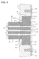
- a sealing structure for wire lead-out hole is illustrated such that a resilient seal member 20 is to be at least partly inserted in a wire lead-out hole 11 formed in a case 10 which protects, for example, an electronic device such as a control panel and a bracket 40 is to be mounted to retain the resilient seal member 20 in the wire lead-out hole 11 as shown in FIG. 4 .
- the wire lead-out hole 11 is composed of or comprises a small-diameter portion 12 extending toward an inner side of the case 10 and a large-diameter portion 13 extending to an outer side of the case 10 and connected to the small-diameter portion 12 via a step as shown in FIG. 4 .
- the large-diameter portion 13 is widened over the entire circumference as compared to the small-diameter portion 12, and an opening formed in an outer surface of the case 10 by the large-diameter portion 13 has a circular shape.
- the wire lead-out hole particularly substantially has a stepped-like configuration (see e.g. FIG. 4 ).
- the smaller-diameter portion 12 particularly has at least part of its inner edges being rounded (particularly along its complete circumference).
- the resilient seal member 20 is, for example, made of a resilient material such as silicone or rubber and includes a (particularly substantially cylindrical) seal main body 21 as shown in FIGS. 1 to 3 .
- the outer diameter of this seal main body 21 is set to be somewhat smaller than the inner diameter of the large-diameter portion 13 of the wire lead-out hole 11.
- the thickness of the seal main body 21 particularly is set to be substantially equal to the length from the opening of the large-diameter portion 13 formed in the case 10 to the small-diameter portion 12. Accordingly, the seal main body 21 at least partly is or can be fitted and/or accommodated into the large-diameter portion 13 of the wire lead-out hole 11 as shown in FIG. 4 .
- One or more, particularly a plurality of (particularly looped or rounded or wiggled) outer lip portions 24 are formed on the outer peripheral surface of the seal main body 21. These outer lip portions 24 are to be held in close contact with the inner peripheral surface of the large-diameter portion 13 (particularly substantially over the entire circumference) to seal between the large-diameter portion 13 and the seal main body 21 in a fluid- or liquid-tight manner as shown in FIG. 4 when the seal main body 21 is at least partly accommodated in the large-diameter portion 13 of the wire lead-out hole 11.
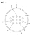
- One or more, particularly a plurality of wire insertion holes 22 substantially extending in a thickness direction of the seal main body 21 is formed in the seal main body 21.
- One or more, particularly a plurality of inner lip portions 23 are formed on the inner peripheral surface of the (particularly each) wire insertion hole 22. These inner lip portions 23 are to be held in close contact with the outer peripheral surface of a wire Y to seal between the wire Y and the seal main body 21 in a fluid- or liquid-tight manner as shown in FIG. 4 when the wire Y is inserted into the wire insertion hole 22.
- the bracket 40 is formed particularly by punching or cutting a plate material (such as a metal plate) by a press.
- a plate material such as a metal plate
- the bracket 40 includes a substantially ring- or O-shaped retaining plate 41 (particularly with a substantially circular shape), an insertion hole 42 formed in (or substantially around) the center of the retaining plate 41, and one or more mounting pieces 43 provided at (particularly substantially opposite and/or upper and lower end portions of) the retaining plate 41.
- the outer diameter of the retaining plate 41 is set to be larger than the inner diameter of the large-diameter portion 13 of the wire lead-out hole 11.
- the insertion hole 42 particularly substantially has a circular shape, and/or the inner diameter thereof is set to be smaller than the outer diameter of the seal main body 21 of the seal member 20.
- the retaining plate 41 closes the large-diameter portion 13 of the wire lead-out hole 11 to retain the resilient seal member 20 at least partly accommodated in the wire lead-out hole 11 as shown in FIG. 4 when the bracket 40 is fixed to the housing 10.
- the inner diameter of the insertion hole 42 is set such that all the wire insertion holes 22 in the seal main body 21 at least partly are accommodated inside the insertion hole 42.
- one or more, particularly a plurality of wires Y drawn out from the wire insertion holes 22 of the seal main body 21 are or can be collectively inserted through the insertion hole 42 as shown in FIG. 4 .
- a bolt insertion hole 43A is formed in (particularly a substantially central part of) each mounting piece 43.
- the bracket 40 is or can be fixed to the case 10 by at least partly inserting tightening bolts V (or mounting plugs) into the bolt insertion holes 43A and tightening or fixing them into the case 10.
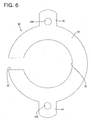
- the bracket 40 may have a C shape by cutting off a part of the retaining plate 41 to form a wire insertion groove 44 as shown in FIG. 6 .
- the bracket 40 can be fixed to the case 10 by inserting the wires Y into the insertion hole 42 through the wire insertion groove 44 after the seal member 20 having the wires Y inserted therethrough beforehand is mounted into the wire lead-out hole 11 without inserting the wires Y through the bracket 40 beforehand.
- a wire protecting portion 25 integrally or unitarily formed to the seal main body 21 projects from an end surface 21A of the seal main body 21 of the resilient seal member 20.
- the wire protecting portion 25 is in the form of a particularly substantially rectangular column with four rounded corners and is narrower than the seal main body 21 over the entire circumference as shown in FIGS. 1 and 3 . It should be understood, however, that the wire protecting portion 25 may be in the form of a polygonal or cylindrical or elliptical shape.
- One or more, particularly a plurality of wire insertion paths 26 are formed in this wire protecting portion 25.
- the wire insertion paths 26 particularly are formed to have the substantially same diameter as the wire insertion holes 22 of the seal main body 21 and communicate with the wire insertion holes 22.
- the wire insertion paths 26 may be formed to have a variable inner diameter (e.g.
- a projecting distance of the wire protecting portion 25 from the seal main body 21 is set to be longer than the length of the small-diameter portion 12 (i.e. its thickness extension in a thickness direction or a direction normal to a plane of the case 10) of the wire lead-out hole 11 in an axial or longitudinal direction.
- the wire protecting portion 25 can prevent the wires Y drawn out from the wire lead-out hole 11 to the interior of the case 10 from coming into contact with the opening 11 A of the wire lead-out hole 11 A and from being damaged.
- the first embodiment is constructed as described above. Next, an operation of mounting the resilient seal member 20 and the bracket 40 is briefly described.
- the wires Y are inserted into the wire insertion paths 26 from the wire protecting portion 25 of the resilient seal member 20 and further into the wire insertion holes 22.
- the wire protecting portion 25 is formed with the wire insertion paths 26 for substantially guiding the wires Y to the wire insertion holes 22, the wires Y can be easily guided to the wire insertion holes 22, wherefore operability in inserting the wires Y can be improved.
- the respective wire insertion paths 26 particularly are independent in the wire protecting portion 25, entanglement of a plurality of wires Y can be prevented.
- the inner lip portions 23 of the wire insertion holes 22 are to be held in close contact with the outer peripheral surfaces of the wires Y to seal between the wires Y and the resilient seal member 20 in a fluid- or liquid-tight manner.
- the resilient seal member 20 having the wires Y inserted therethrough at least partly is fitted into the wire lead-out hole 11 from the outer side of the case 10 and inserted until the end surface 21 A of the seal main body 21 substantially comes into surface contact with a step surface as a boundary between the small-diameter portion 12 and the large-diameter portion 13 of the wire lead-out hole 11.
- the wire protecting portion 25 projects into the case 10 through the opening of the small-diameter portion 12 of the wire lead-out hole 11
- the wires Y can be prevented from coming into contact with the opening 11 A of the wire lead-out hole 11 and from being damaged.
- the outer lip portions 24 of the seal main body 21 are held in close contact with the inner peripheral surface of the wire lead-out hole 11 to seal between the case 10 and the resilient seal member 20 in a fluid-or liquid-tight manner. Further, a pressure acts toward the center of the seal main body 21 by the close contact of the outer lip portions 24 with the inner peripheral surface of the wire lead-out hole 11 over the entire circumference, whereby the inner lip portions 23 are more closely held substantially in contact with the outer peripheral surfaces of the wires Y. Thus, entrance of dust, water and the like into the case 10 can be reliably prevented.
- the bracket 40 is pressed from the outer side of the wire lead-out hole 11 and the one or more tightening bolts V are tightened into the case 10, whereby the bracket 40 is fixed to the case 10 while retaining the resilient seal member 20.
- the contact of the wires Y with the opening 11 A of the wire lead-out hole 11 can be prevented and the number of the parts of the sealing structure in the wire lead-out hole 11 can be reduced to about half as compared with conventional products.
- an operation of inserting the wires Y through the respective parts beforehand is reduced to half and an assembling operation by an operator can be drastically improved.
- the number of parts through which the wires Y are inserted is reduced, troubles such as an error in an insertion order can also be prevented.
- the wires Y need not be inserted through the bracket 40 beforehand. Troubles such as an error in an insertion order do not occur at all and a burden on the operator can be drastically reduced. Further, a reduction in the number of the parts can contribute to a cost reduction.
- a sealing structure of the second embodiment differs from the first embodiment in the construction of the wire protecting portion 25 of the resilient seal member 20.
- the similar or substantially same constructions as in the first embodiment are identified by the same reference numerals. Further, the similar or substantially same constructions, functions and effects as in the first embodiment are not described.
- a wire protecting portion 25 of a resilient seal member 20 in the second embodiment is formed with a wire insertion recess 27 in an end surface 25A (projecting surface of the wire protecting portion 25) substantially opposite to a seal main body 21 as shown in FIG. 8 .
- the peripheral wall of the wire insertion recess 27 is set to have such a thickness as to be substantially resiliently deformable.
- All wire insertion holes 22 of the seal main body 21 are open in a back wall 27A of the wire insertion recess 27, and the wire insertion recess 27 and all the wire insertion holes 22 communicate.
- a mold needs to be formed with long and narrow shaft portions having a length which is the sum of the length of the seal main body 21 and that of the wire protecting portion 25.
- the length of the shaft portions of the mold can be set at the length of the seal main body and strength of the shaft portions can be increased as compared with a mold including long and narrow shaft portions having a length equal to the sum of the length of the seal main body and that of the wire protecting portion.
- a mold structure can be simplified as compared with a mold including shaft portions longer than the length of the seal main body 21, which is effective in suppressing mold cost.
- a sealing structure of the third embodiment differs from the second embodiment in the construction of the wire protecting portion 25 of the resilient seal member 20.
- the similar or substantially same constructions as in the second embodiment are identified by the same reference numerals. Further, the similar or substantially same constructions, functions and effects as in the second embodiment are not described.
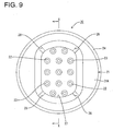
- slits 28 are formed in the peripheral wall of the wire protecting portion 25 as shown in FIGS. 9 and 10 . These slits 28 are formed at or near four corners of the wire protecting portion 25 and/or substantially extend straight from an opening of a wire insertion recess 27 toward a seal main body 21.
- a sealing structure for wire lead-out hole which is simple in structure and can reduce the number of parts
- a sealing structure for wire lead-out hole is provided with a wire lead-out hole 11 formed in a case 10, a resilient seal member 20 to be mounted into the wire lead-out hole 11, and a bracket 40 for retaining the resilient seal member 20 in the wire lead-out hole 11 by being fixed to the case 10.
- the resilient seal member includes a seal main body 21 including one or more, particularly a plurality of wire insertion holes 22 for allowing insertion of wires Y, one or more outer lip portions 24 formed on the outer peripheral surface of the seal main body 21, one or more inner lip portions 23 formed on the inner peripheral surfaces of the one or more wire insertion holes 22, and a wire protecting portion 25 provided on the seal main body 21.
Landscapes
- Engineering & Computer Science (AREA)
- Architecture (AREA)
- Civil Engineering (AREA)
- Structural Engineering (AREA)
- General Engineering & Computer Science (AREA)
- Mechanical Engineering (AREA)
- Installation Of Indoor Wiring (AREA)
- Connector Housings Or Holding Contact Members (AREA)
- Insertion, Bundling And Securing Of Wires For Electric Apparatuses (AREA)
Abstract
Description
- The present invention relates to a sealing structure for wire lead-out hole and to a sealing method therefor.
- A wire clamp disclosed in Japanese Unexamined Patent Publication No.
2001-21066 - However, in this type of the sealing structure for wire lead-out hole, the wire needs to be inserted through a plurality of parts such as the clamp main body, the resilient sleeve and the respective sealing members (rubber packing, O-rings) when the wire is mounted into the wire lead-out hole, and assembling operability is poor. If there is an error in an inserting order of the wire through the respective parts or it is forgotten to insert the wire through some of the parts, it is necessary to remove the respective parts from the wire and insert the wire again. Thus, working efficiency becomes very poor. Since the wire clamp of this type uses a plurality of parts with complicated structures, there is a problem of increasing cost.
- The present invention was developed in view of the above situation and an object thereof is to allow a simple sealing of a wire lead-out hole.
- This object is solved according to the invention by the features of the independent claims. Particular embodiments are subject of the dependent claims. Accordingly, the sealing structure for wire lead-out hole is simple in structure and can reduce the number of parts
- According to the invention, there is provided a sealing structure for wire lead-out hole, comprising a wire lead-out hole formed in a case and substantially having a stepped configuration in which a large-diameter portion and a small-diameter portion are connected; a resilient seal member to be at least partly mounted into the wire lead-out hole; and a retaining or pressing member for retaining the resilient seal member in the wire lead-out hole by being fixed to the case; wherein the resilient seal member includes a seal main body including a wire insertion hole for allowing insertion of a wire; at least one outer lip portion formed on the outer peripheral surface of the seal main body and to be held in close contact with the inner peripheral surface of the large-diameter portion; at least one inner lip portion formed on the inner peripheral surface of the wire insertion hole and to be held in close contact with the outer peripheral surface of the wire; and a wire protecting portion projecting from one end surface of the seal main body and to be provided between the inner peripheral surface of the small-diameter portion and the outer peripheral surface of the wire.
- According to the thus constructed sealing structure, entrance of fluid or a liquid such as water, or other elements such as dust and the like through a clearance between the wire and the case can be prevented and the wire protecting portion can prevent the wire from being damaged due to contact with an opening of a small-diameter portion of the wire lead-out hole. Further, by reducing the number of parts as compared with conventional products, it becomes possible to reduce troubles caused such as by man-hour required for insertion of the wire through the respective parts and a mounting error at the time of wire insertion, wherefore a burden on an operator can be reduced. Further, a reduction in the number of the parts can contribute to a cost reduction.
- The present invention may be particularly embodied to have the following constructions.
- The wire protecting portion may project outwardly of the wire lead-out hole from an opening of the wire lead-out hole. According to this construction, the contact of the wire with the opening of the wire lead-out hole can be reliably prevented.
- The seal main body may include a plurality of wire insertion holes; and a plurality of wire insertion paths which communicate with the plurality of wire insertion holes may be formed in the wire protecting portion. According to this construction, the plurality of wires can be easily guided to the wire insertion holes and entanglement of the wires in the wire protecting portion can be prevented.
- The wire protecting portion may be formed with a wire insertion recess which is open at an end surface opposite to the seal main body and with which all the wire insertion holes communicate.
- To form a seal member including long and narrow holes continuous with wire insertion holes in a wire protecting portion by injection molding, it is necessary to prepare a mold including long and narrow shaft portions having a length which is the sum of the length of a seal main body and that of the wire protecting portion. However, according to this construction, the length of the shaft portions of the mold can be set at the length of the seal main body and strength of the shaft portions can be increased as compared with a mold including long and narrow shaft portions having a length equal to the sum of the length of the seal main body and that of the wire protecting portion. Further, a mold structure can be simplified, which is effective in suppressing mold cost. Further, since the interior of the wire insertion recess requires no material upon forming the resilient seal member, material cost can be reduced by the volume of the wire insertion recess.
- A plurality of slits may be formed in the peripheral wall of the wire insertion recess from an opening of the wire insertion recess toward the seal main body. According to this construction, in the case of inserting the wire into the wire insertion path from the wire protecting portion, the wire can be inserted while the peripheral wall of the wire protecting portion is turned outwardly. Thus, operability in assembling the wire can be improved.
- The retaining or pressing member may comprise a bracket including a retaining plate which includes an insertion hole for allowing insertion of the wire and can come into contact with an end surface of the seal main body.
- The retaining or pressing member may comprise one or more, preferably a pair of mounting pieces which are located at end portions of the retaining plate and fix the retaining plate to the case.
- The retaining or pressing member may be or may comprise a bracket including a retaining plate which includes an insertion hole for allowing insertion of the wire and can come into contact with an end surface of the seal main body and a pair of mounting pieces which are located at end portions of the retaining plate and fix the retaining plate to the case. According to this construction, the bracket for retaining the resilient seal member can be produced very easily and at low cost by punching a metal plate by a press.
- The retaining plate may be formed with a wire insertion groove for allowing insertion of the wire between the outer peripheral surface of the retaining plate and the inner peripheral surface of the insertion hole. According to this construction, it is not necessary to insert the wire through the bracket beforehand, and the wire can be inserted-into the insertion hole through the wire insertion groove and the bracket can be fixed to the case after the resilient seal member having the wire inserted therethrough beforehand is mounted into the wire lead-out hole. Thus, assembling operability can be improved.
- According to the invention, there is further provided a method of sealing a wire lead-out hole formed in a case and substantially having a stepped configuration in which a large-diameter portion and a small-diameter portion are connected, comprising the following steps:
- inserting a wire into a wire insertion hole of a seal main body of a resilient seal member, wherein at least one inner lip portion formed on the inner peripheral surface of the wire insertion hole is brought into close contact with the outer peripheral surface of the wire;
- at least partly mounting the resilient seal member into the wire lead-out hole, wherein:
- at least one outer lip portion formed on the outer peripheral surface of the seal main body is brought into close contact with the inner peripheral surface of the large-diameter portion, and
- a wire protecting portion projecting from one end surface of the seal main body is provided between the inner peripheral surface of the small-diameter portion and the outer peripheral surface of the wire; and
- retaining the resilient seal member in the wire lead-out hole by means of a retaining or pressing member being fixed to the case.
- The above method may be particularly embodied as follows:
- The wire protecting portion may be arranged such as to project outwardly of the wire lead-out hole from an opening of the wire lead-out hole.
- The seal main body may include a plurality of wire insertion holes; and a plurality of wire insertion paths which communicate with the plurality of wire insertion holes may be formed in the wire protecting portion.
- The wire protecting portion may be formed with a wire insertion recess which is open at an end surface opposite to the seal main body and with which all the wire insertion holes communicate.
- A plurality of slits may be formed in the peripheral wall of the wire insertion recess from an opening of the wire insertion recess toward the seal main body.
- The sealing method may further comprise inserting the wire into an insertion hole of a retaining plate of the pressing member, wherein the pressing member is brought into contact with an end surface of the seal main body.
- The sealing method may further comprise fixing the retaining or pressing member by means of one or more, preferably a pair of mounting pieces thereof which are located at end portions of the retaining plate and fix the retaining plate to the case.
- According to the above, it is possible to provide a sealing structure which is simple in structure and can reduce the number of parts.
- These and other objects, features and advantages of the present invention will become more apparent upon reading of the following detailed description of preferred embodiments and accompanying drawings. It should be understood that even though embodiments are separately described, single features thereof may be combined to additional embodiments.
-
FIG. 1 is a front view of a resilient seal member according to a first embodiment, -
FIG. 2 is a rear view of the resilient seal member, -
FIG. 3 is a section along III-III ofFIG. 1 , -
FIG. 4 is a section showing a state where the resilient seal member and a bracket are mounted in and at a wire lead-out hole of a case, -
FIG. 5 is a front view of a bracket including an O-shaped retaining plate, -
FIG. 6 is a front view of a bracket including a C-shaped retaining plate, -
FIG. 7 is a front view of a resilient seal member according to a second embodiment, -
FIG. 8 is a section along VIII-VIII ofFIG. 7 , -
FIG. 9 is a front view of a resilient seal member according to a third embodiment, and -
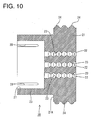
FIG. 10 is a section along X-X ofFIG. 9 . - A first particular embodiment of the present invention is described with reference to
FIGS. 1 to 6 . - A sealing structure for wire lead-out hole according to this embodiment is illustrated such that a
resilient seal member 20 is to be at least partly inserted in a wire lead-outhole 11 formed in acase 10 which protects, for example, an electronic device such as a control panel and abracket 40 is to be mounted to retain theresilient seal member 20 in the wire lead-outhole 11 as shown inFIG. 4 . - The wire lead-
out hole 11 is composed of or comprises a small-diameter portion 12 extending toward an inner side of thecase 10 and a large-diameter portion 13 extending to an outer side of thecase 10 and connected to the small-diameter portion 12 via a step as shown inFIG. 4 . The large-diameter portion 13 is widened over the entire circumference as compared to the small-diameter portion 12, and an opening formed in an outer surface of thecase 10 by the large-diameter portion 13 has a circular shape. Accordingly, the wire lead-out hole particularly substantially has a stepped-like configuration (see e.g.FIG. 4 ). The smaller-diameter portion 12 particularly has at least part of its inner edges being rounded (particularly along its complete circumference). - The
resilient seal member 20 is, for example, made of a resilient material such as silicone or rubber and includes a (particularly substantially cylindrical) sealmain body 21 as shown inFIGS. 1 to 3 . The outer diameter of this sealmain body 21 is set to be somewhat smaller than the inner diameter of the large-diameter portion 13 of the wire lead-out hole 11. Further, the thickness of the sealmain body 21 particularly is set to be substantially equal to the length from the opening of the large-diameter portion 13 formed in thecase 10 to the small-diameter portion 12. Accordingly, the sealmain body 21 at least partly is or can be fitted and/or accommodated into the large-diameter portion 13 of the wire lead-out hole 11 as shown inFIG. 4 . - One or more, particularly a plurality of (particularly looped or rounded or wiggled)
outer lip portions 24 are formed on the outer peripheral surface of the sealmain body 21. Theseouter lip portions 24 are to be held in close contact with the inner peripheral surface of the large-diameter portion 13 (particularly substantially over the entire circumference) to seal between the large-diameter portion 13 and the sealmain body 21 in a fluid- or liquid-tight manner as shown inFIG. 4 when the sealmain body 21 is at least partly accommodated in the large-diameter portion 13 of the wire lead-out hole 11. - One or more, particularly a plurality of wire insertion holes 22 substantially extending in a thickness direction of the seal
main body 21 is formed in the sealmain body 21. One or more, particularly a plurality ofinner lip portions 23 are formed on the inner peripheral surface of the (particularly each)wire insertion hole 22. Theseinner lip portions 23 are to be held in close contact with the outer peripheral surface of a wire Y to seal between the wire Y and the sealmain body 21 in a fluid- or liquid-tight manner as shown inFIG. 4 when the wire Y is inserted into thewire insertion hole 22. - On the other hand, the
bracket 40 is formed particularly by punching or cutting a plate material (such as a metal plate) by a press. As shown inFIG. 5 , thebracket 40 includes a substantially ring- or O-shaped retaining plate 41 (particularly with a substantially circular shape), aninsertion hole 42 formed in (or substantially around) the center of the retainingplate 41, and one or more mountingpieces 43 provided at (particularly substantially opposite and/or upper and lower end portions of) the retainingplate 41. - The outer diameter of the retaining
plate 41 is set to be larger than the inner diameter of the large-diameter portion 13 of the wire lead-out hole 11. - The
insertion hole 42 particularly substantially has a circular shape, and/or the inner diameter thereof is set to be smaller than the outer diameter of the sealmain body 21 of theseal member 20. Thus, the retainingplate 41 closes the large-diameter portion 13 of the wire lead-out hole 11 to retain theresilient seal member 20 at least partly accommodated in the wire lead-out hole 11 as shown inFIG. 4 when thebracket 40 is fixed to thehousing 10. - The inner diameter of the
insertion hole 42 is set such that all the wire insertion holes 22 in the sealmain body 21 at least partly are accommodated inside theinsertion hole 42. Thus, one or more, particularly a plurality of wires Y drawn out from the wire insertion holes 22 of the sealmain body 21 are or can be collectively inserted through theinsertion hole 42 as shown inFIG. 4 . - A
bolt insertion hole 43A is formed in (particularly a substantially central part of) each mountingpiece 43. As shown inFIG. 4 , thebracket 40 is or can be fixed to thecase 10 by at least partly inserting tightening bolts V (or mounting plugs) into thebolt insertion holes 43A and tightening or fixing them into thecase 10. Note that thebracket 40 may have a C shape by cutting off a part of the retainingplate 41 to form awire insertion groove 44 as shown inFIG. 6 . By this, thebracket 40 can be fixed to thecase 10 by inserting the wires Y into theinsertion hole 42 through thewire insertion groove 44 after theseal member 20 having the wires Y inserted therethrough beforehand is mounted into the wire lead-out hole 11 without inserting the wires Y through thebracket 40 beforehand. - A
wire protecting portion 25 integrally or unitarily formed to the sealmain body 21 projects from anend surface 21A of the sealmain body 21 of theresilient seal member 20. - The
wire protecting portion 25 is in the form of a particularly substantially rectangular column with four rounded corners and is narrower than the sealmain body 21 over the entire circumference as shown inFIGS. 1 and3 . It should be understood, however, that thewire protecting portion 25 may be in the form of a polygonal or cylindrical or elliptical shape. One or more, particularly a plurality ofwire insertion paths 26 are formed in thiswire protecting portion 25. Thewire insertion paths 26 particularly are formed to have the substantially same diameter as the wire insertion holes 22 of the sealmain body 21 and communicate with the wire insertion holes 22. In a specific embodiment, thewire insertion paths 26 may be formed to have a variable inner diameter (e.g. a substantially conical diameter) being decreasing along the longitudinal direction of thewire protecting portion 25 towards the wire insertion holes 22, wherein the diameter at the distal end of thewire insertion paths 26 is substantially equal to that of the wire insertion holes 22 so as to allow a smooth passage of the inserted wire from the thewire insertion paths 26 to the wire insertion holes 22. A projecting distance of thewire protecting portion 25 from the sealmain body 21 is set to be longer than the length of the small-diameter portion 12 (i.e. its thickness extension in a thickness direction or a direction normal to a plane of the case 10) of the wire lead-out hole 11 in an axial or longitudinal direction. Thus, when theresilient seal member 20 is inserted into the wire lead-out hole 11, a base end portion of thewire protecting portion 25 is arranged in the small-diameter portion 12 of the wire lead-out hole 11 and the remaining part projects toward the inner side of thecase 10 from the small-diameter portion 12. Thus, thewire protecting portion 25 can prevent the wires Y drawn out from the wire lead-out hole 11 to the interior of thecase 10 from coming into contact with theopening 11 A of the wire lead-out hole 11 A and from being damaged. - The first embodiment is constructed as described above. Next, an operation of mounting the
resilient seal member 20 and thebracket 40 is briefly described. - First, the wires Y are inserted into the
wire insertion paths 26 from thewire protecting portion 25 of theresilient seal member 20 and further into the wire insertion holes 22. In this process, since thewire protecting portion 25 is formed with thewire insertion paths 26 for substantially guiding the wires Y to the wire insertion holes 22, the wires Y can be easily guided to the wire insertion holes 22, wherefore operability in inserting the wires Y can be improved. Further, since the respectivewire insertion paths 26 particularly are independent in thewire protecting portion 25, entanglement of a plurality of wires Y can be prevented. - Further, the
inner lip portions 23 of the wire insertion holes 22 are to be held in close contact with the outer peripheral surfaces of the wires Y to seal between the wires Y and theresilient seal member 20 in a fluid- or liquid-tight manner. - Subsequently, the
resilient seal member 20 having the wires Y inserted therethrough at least partly is fitted into the wire lead-out hole 11 from the outer side of thecase 10 and inserted until theend surface 21 A of the sealmain body 21 substantially comes into surface contact with a step surface as a boundary between the small-diameter portion 12 and the large-diameter portion 13 of the wire lead-out hole 11. At this time, since thewire protecting portion 25 projects into thecase 10 through the opening of the small-diameter portion 12 of the wire lead-out hole 11, the wires Y can be prevented from coming into contact with theopening 11 A of the wire lead-out hole 11 and from being damaged. Further, theouter lip portions 24 of the sealmain body 21 are held in close contact with the inner peripheral surface of the wire lead-out hole 11 to seal between thecase 10 and theresilient seal member 20 in a fluid-or liquid-tight manner. Further, a pressure acts toward the center of the sealmain body 21 by the close contact of theouter lip portions 24 with the inner peripheral surface of the wire lead-out hole 11 over the entire circumference, whereby theinner lip portions 23 are more closely held substantially in contact with the outer peripheral surfaces of the wires Y. Thus, entrance of dust, water and the like into thecase 10 can be reliably prevented. - After the
resilient seal member 20 is completely or properly inserted into the wire lead-out hole 11, thebracket 40 is pressed from the outer side of the wire lead-out hole 11 and the one or more tightening bolts V are tightened into thecase 10, whereby thebracket 40 is fixed to thecase 10 while retaining theresilient seal member 20. - As described above, in this embodiment, the contact of the wires Y with the
opening 11 A of the wire lead-out hole 11 can be prevented and the number of the parts of the sealing structure in the wire lead-out hole 11 can be reduced to about half as compared with conventional products. Thus, an operation of inserting the wires Y through the respective parts beforehand is reduced to half and an assembling operation by an operator can be drastically improved. Further, since the number of parts through which the wires Y are inserted is reduced, troubles such as an error in an insertion order can also be prevented. In the case of providing thebracket 40 with thewire insertion groove 44, the wires Y need not be inserted through thebracket 40 beforehand. Troubles such as an error in an insertion order do not occur at all and a burden on the operator can be drastically reduced. Further, a reduction in the number of the parts can contribute to a cost reduction. - Next, a second particular embodiment of the present invention is described with reference to
FIGS. 7 and8 . A sealing structure of the second embodiment differs from the first embodiment in the construction of thewire protecting portion 25 of theresilient seal member 20. The similar or substantially same constructions as in the first embodiment are identified by the same reference numerals. Further, the similar or substantially same constructions, functions and effects as in the first embodiment are not described. - A
wire protecting portion 25 of aresilient seal member 20 in the second embodiment is formed with awire insertion recess 27 in anend surface 25A (projecting surface of the wire protecting portion 25) substantially opposite to a sealmain body 21 as shown inFIG. 8 . Thus, the peripheral wall of thewire insertion recess 27 is set to have such a thickness as to be substantially resiliently deformable. All wire insertion holes 22 of the sealmain body 21 are open in aback wall 27A of thewire insertion recess 27, and thewire insertion recess 27 and all the wire insertion holes 22 communicate. - According to this construction, particularly material cost can be reduced by the volume of the
wire insertion recess 27 upon forming theresilient seal member 20. In order to form long and narrow holes (wire insertion paths 26 in the first embodiment) continuous with the wire insertion holes 22 in thewire protecting portion 25, a mold needs to be formed with long and narrow shaft portions having a length which is the sum of the length of the sealmain body 21 and that of thewire protecting portion 25. However, by providing thewire protecting portion 25 with thewire insertion recess 27, the length of the shaft portions of the mold can be set at the length of the seal main body and strength of the shaft portions can be increased as compared with a mold including long and narrow shaft portions having a length equal to the sum of the length of the seal main body and that of the wire protecting portion. Further, a mold structure can be simplified as compared with a mold including shaft portions longer than the length of the sealmain body 21, which is effective in suppressing mold cost. - Next, a third particular embodiment of the present invention is described with reference to
FIGS. 9 and10 . A sealing structure of the third embodiment differs from the second embodiment in the construction of thewire protecting portion 25 of theresilient seal member 20. The similar or substantially same constructions as in the second embodiment are identified by the same reference numerals. Further, the similar or substantially same constructions, functions and effects as in the second embodiment are not described. - In a
wire protecting portion 25 of the third embodiment, slits 28 are formed in the peripheral wall of thewire protecting portion 25 as shown inFIGS. 9 and10 . Theseslits 28 are formed at or near four corners of thewire protecting portion 25 and/or substantially extend straight from an opening of awire insertion recess 27 toward a sealmain body 21. - According to this construction, in the case of inserting wires into wire insertion holes 22 from the
wire insertion recess 27, an operator's hand can be inserted to the back of thewire insertion recess 27 by turning the peripheral wall of thewire protecting portion 25 outwardly. Thus, ends of wires Y can be more easily inserted into the wire insertion holes 22 and operability in mounting the wires Y can be improved. - Accordingly, to provide a sealing structure for wire lead-out hole which is simple in structure and can reduce the number of parts, a sealing structure for wire lead-out hole is provided with a wire lead-
out hole 11 formed in acase 10, aresilient seal member 20 to be mounted into the wire lead-out hole 11, and abracket 40 for retaining theresilient seal member 20 in the wire lead-out hole 11 by being fixed to thecase 10. The resilient seal member includes a sealmain body 21 including one or more, particularly a plurality of wire insertion holes 22 for allowing insertion of wires Y, one or moreouter lip portions 24 formed on the outer peripheral surface of the sealmain body 21, one or moreinner lip portions 23 formed on the inner peripheral surfaces of the one or more wire insertion holes 22, and awire protecting portion 25 provided on the sealmain body 21. - The present invention is not limited to the above described and illustrated embodiments. For example, the following embodiments are also included in the technical scope of the present invention as defined by the claims.
- (1) Although the length of the
wire protecting portion 25 is longer (in an axial or longitudinal direction) than that of the small-diameter portion 12 of the wire lead-out hole 11 in the above embodiments, the present invention is not limited to such a mode. According to the present invention, the length of thewire protecting portion 25 may be, for example, set to be substantially equal to that of the small-diameter portion 12. The length of thewire protecting portion 25 may be so set that the wires Y inserted into thewire protecting portion 25 do not come into contact with the opening of the wire lead-out hole 11. - (2) Although the
wire protecting portion 25 is in the form of a rectangular column with four rounded corners in the above embodiments, the present invention is not limited to such a mode and thewire protecting portion 25 may be, for example, in the form of a cylinder. - (3) Although the small-
diameter portion 12 of the wire lead-out hole 11 is provided at the inner side of thecase 10 and the large-diameter portion 13 is arranged at the outer side of thecase 10, the present invention is not limited to such a mode. The small-diameter portion 12 of the wire lead-out hole 11 may be provided at the outer side of thecase 10, the large-diameter portion 13 may be provided at the inner side of thecase 10, and theseal member 40 20 may be retained by thebracket 40 from the inner side of thecase 10. - (4) Although the
slits 28 are formed at or near the four corners of the peripheral wall of thewire protecting portion 25 in the third embodiment, the present invention is not limited to such a mode. For example, the number of slits may be increased or decreased according to the thickness of the peripheral wall of thewire protecting portion 25 to such an extent that the peripheral wall is not naturally deflected. -
- 10:
- case
- 11:
- wire lead-out hole
- 12:
- small-diameter portion
- 13:
- large-diameter portion
- 20:
- resilient seal member
- 21:
- seal main body
- 22:
- wire insertion hole
- 23:
- inner lip portion
- 24:
- outer lip portion
- 25:
- wire protecting portion
- 26:
- wire insertion path
- 27:
- wire insertion recess
- 28:
- slit
- 40:
- bracket (pressing member)
- 41:
- retaining plate
- 42:
- insertion hole
- 43:
- mounting piece
- 44:
- wire insertion groove
- Y:
- wire
Claims (15)
- A sealing structure for wire lead-out hole (11), comprising a wire lead-out hole (11) formed in a case (10) and substantially having a stepped configuration in which a large-diameter portion (13) and a small-diameter portion (12) are connected; a resilient seal member (20) to be at least partly mounted into the wire lead-out hole (11); and a retaining or pressing member (40) for retaining the resilient seal member (20) in the wire lead-out hole (11) by being fixed to the case (10); wherein the resilient seal member (20) includes:a seal main body (21) including a wire insertion hole (22) for allowing insertion of a wire (Y);at least one outer lip portion (24) formed on the outer peripheral surface of the seal main body (21) and to be held in close contact with the inner peripheral surface of the large-diameter portion (13);at least one inner lip portion (23) formed on the inner peripheral surface of the wire insertion hole (22) and to be held in close contact with the outer peripheral surface of the wire (Y); anda wire protecting portion (25) projecting from one end surface of the seal main body (21) and to be provided between the inner peripheral surface of the small-diameter portion (12) and the outer peripheral surface of the wire (Y).
- A sealing structure according to claim 1, wherein the wire protecting portion (25) projects outwardly of the wire lead-out hole (11) from an opening of the wire lead-out hole (11).
- A sealing structure according to any one of the preceding claims, wherein:the seal main body (21) includes a plurality of wire insertion holes (22); anda plurality of wire insertion paths (26) which communicate with the plurality of wire insertion holes (22) are formed in the wire protecting portion (25).
- A sealing structure according to any one of the preceding claims, wherein the wire protecting portion (25) is formed with a wire insertion recess (27) which is open at an end surface opposite to the seal main body (21) and with which all the wire insertion holes (22) communicate.
- A sealing structure according to claim 4, wherein a plurality of slits (28) are formed in the peripheral wall of the wire insertion recess (27) from an opening of the wire insertion recess (27) toward the seal main body (21).
- A sealing structure according to any one of the preceding claims, wherein the retaining or pressing member (40) comprises a bracket including a retaining plate (41) which includes an insertion hole (42) for allowing insertion of the wire (Y) and can come into contact with an end surface of the seal main body (21).
- A sealing structure according to claim 6, wherein the retaining or pressing member (40) comprises one or more, preferably a pair of mounting pieces (43) which are located at end portions of the retaining plate (41) and fix the retaining plate (41) to the case (10).
- A sealing structure according to claim 6 or 7, wherein the retaining plate (41) is formed with a wire insertion groove (44) for allowing insertion of the wire (Y) between the outer peripheral surface of the retaining plate (41) and the inner peripheral surface of the insertion hole (42).
- A method of sealing a wire lead-out hole (11) formed in a case (10) and substantially having a stepped configuration in which a large-diameter portion (13) and a small-diameter portion (12) are connected, comprising the following steps:inserting a wire (Y) into a wire insertion hole (22) of a seal main body (21) of a resilient seal member (20), wherein at least one inner lip portion (23) formed on the inner peripheral surface of the wire insertion hole (22) is brought into close contact with the outer peripheral surface of the wire (Y);at least partly mounting the resilient seal member (20) into the wire lead-out hole (11), wherein:at least one outer lip portion (24) formed on the outer peripheral surface of the seal main body (21) is brought into close contact with the inner peripheral surface of the large-diameter portion (13), anda wire protecting portion (25) projecting from one end surface of the seal main body (21) is provided between the inner peripheral surface of the small-diameter portion (12) and the outer peripheral surface of the wire (Y); andretaining the resilient seal member (20) in the wire lead-out hole (11) by means of a retaining or pressing member (40) being fixed to the case (10).
- A sealing method according to claim 9, wherein the wire protecting portion (25) is arranged such as to project outwardly of the wire lead-out hole (11) from an opening of the wire lead-out hole (11).
- A sealing method according to claim 9 or 10, wherein the seal main body (21) includes a plurality of wire insertion holes (22); and a plurality of wire insertion paths (26) which communicate with the plurality of wire insertion holes (22) are formed in the wire protecting portion (25).
- A sealing method according to any one of the preceding claims 9 to 11, wherein the wire protecting portion (25) is formed with a wire insertion recess (27) which is open at an end surface opposite to the seal main body (21) and with which all the wire insertion holes (22) communicate.
- A sealing method according to claim 12, wherein a plurality of slits (28) are formed in the peripheral wall of the wire insertion recess (27) from an opening of the wire insertion recess (27) toward the seal main body (21).
- A sealing method according to any one of the preceding claims 9 to 13, further comprising inserting the wire (Y) into an insertion hole (42) of a retaining plate (41) of the pressing member (40), wherein the pressing member (40) is brought into contact with an end surface of the seal main body (21).
- A sealing method according to claim 14, further comprising fixing the retaining or pressing member (40) by means of one or more, preferably a pair of mounting pieces (43) thereof which are located at end portions of the retaining plate (41) and fix the retaining plate (41) to the case (10).
Applications Claiming Priority (1)
| Application Number | Priority Date | Filing Date | Title |
|---|---|---|---|
| JP2010120653A JP5521777B2 (en) | 2010-05-26 | 2010-05-26 | Seal structure of wire lead-out hole |
Publications (2)
| Publication Number | Publication Date |
|---|---|
| EP2390962A1 true EP2390962A1 (en) | 2011-11-30 |
| EP2390962B1 EP2390962B1 (en) | 2014-05-07 |
Family
ID=44168881
Family Applications (1)
| Application Number | Title | Priority Date | Filing Date |
|---|---|---|---|
| EP11003487.3A Not-in-force EP2390962B1 (en) | 2010-05-26 | 2011-04-28 | Sealing structure for wire lead-out hole and sealing method therefor |
Country Status (5)
| Country | Link |
|---|---|
| US (1) | US8410360B2 (en) |
| EP (1) | EP2390962B1 (en) |
| JP (1) | JP5521777B2 (en) |
| KR (1) | KR20110129814A (en) |
| CN (1) | CN102361286B (en) |
Cited By (3)
| Publication number | Priority date | Publication date | Assignee | Title |
|---|---|---|---|---|
| CN108933412A (en) * | 2017-05-24 | 2018-12-04 | 佛山市顺德区美的饮水机制造有限公司 | Terminal clamp and household electrical appliance |
| US11495908B2 (en) | 2019-04-01 | 2022-11-08 | Aptiv Technologies Limited | Electrical connector assembly with liquid cooling features |
| US11539158B2 (en) * | 2019-09-09 | 2022-12-27 | Aptiv Technologies Limited | Electrical terminal seal and electrical connector containing same |
Families Citing this family (25)
| Publication number | Priority date | Publication date | Assignee | Title |
|---|---|---|---|---|
| JP5056619B2 (en) * | 2008-06-30 | 2012-10-24 | 株式会社明電舎 | Cable mounting structure for electrical equipment |
| USD682817S1 (en) * | 2012-02-24 | 2013-05-21 | Research In Motion Limited | Electronic device shell |
| US8898974B1 (en) * | 2012-11-20 | 2014-12-02 | Amazon Technologies, Inc. | Electrical panel structures |
| CN103225715B (en) * | 2013-04-26 | 2015-05-06 | 华为技术有限公司 | Seal assembly |
| US9553440B2 (en) * | 2013-11-18 | 2017-01-24 | Walbro Llc | Wire seal assembly |
| WO2016173543A1 (en) * | 2015-04-30 | 2016-11-03 | 爱德奇电讯国际贸易(上海)有限公司 | Elastic sealing element and sealing assembly |
| CN104812196A (en) * | 2015-05-19 | 2015-07-29 | 国家电网公司 | Incoming and outgoing line blocking clamp for communication cabinet |
| JP6672824B2 (en) * | 2016-01-20 | 2020-03-25 | セイコーエプソン株式会社 | Electro-optical devices, lighting devices, and projectors |
| CN107182182B (en) * | 2016-03-11 | 2019-11-08 | 车王电子(宁波)有限公司 | Electronic Control Box |
| AU2016202422A1 (en) * | 2016-04-15 | 2017-11-02 | Lumen International Holdings Pty Ltd | Fuse Terminal Wire Seal |
| JP6340036B2 (en) * | 2016-06-07 | 2018-06-06 | 矢崎総業株式会社 | Exterior end cap and wire harness |
| USD813855S1 (en) * | 2016-07-13 | 2018-03-27 | Htc Corporation | Cover for electronic device |
| US10700502B2 (en) * | 2016-11-02 | 2020-06-30 | RPH Intellectual Holdings, LLC | Wall penetration panel |
| JP2018125193A (en) * | 2017-02-01 | 2018-08-09 | 住友電装株式会社 | Waterproof connector |
| JP6978849B2 (en) * | 2017-04-20 | 2021-12-08 | スタンレー電気株式会社 | Grommets for vehicle lighting |
| US10312630B1 (en) * | 2018-01-08 | 2019-06-04 | Yazaki North America, Inc. | Device and method for protecting a connector assembly |
| JP6924387B2 (en) * | 2018-03-15 | 2021-08-25 | 株式会社オートネットワーク技術研究所 | Wire holding structure |
| US20200194981A1 (en) * | 2018-12-14 | 2020-06-18 | Ge Aviation Systems, Llc | Electrical wire sealing assembly |
| US12349300B2 (en) * | 2019-09-30 | 2025-07-01 | Kuwana Metals, Ltd. | Airtight connection unit, airtight connection assembly, airtight container and vaporizer, as well as production method of airtight connection assembly |
| CN112787282A (en) * | 2019-11-08 | 2021-05-11 | 无锡恩福油封有限公司 | Sealing block |
| KR102374758B1 (en) * | 2020-07-28 | 2022-03-15 | 주식회사 경신 | Waterproof cap connection device of junction block |
| TWI847709B (en) * | 2023-05-19 | 2024-07-01 | 天心工業股份有限公司 | Hub motor |
| KR102724238B1 (en) * | 2023-07-14 | 2024-10-31 | (주)미성지엘비 | Wire insulation device for the building switch box |
| EP4560653A1 (en) * | 2023-11-23 | 2025-05-28 | TE Connectivity India Private Limited | Wire seal and method for sealing a wire feed-through |
| DE102025133800A1 (en) * | 2024-09-12 | 2026-03-12 | Sew-Eurodrive Gmbh & Co Kg | Device comprising a housing part and a sealing part, in particular a cable gland |
Citations (6)
| Publication number | Priority date | Publication date | Assignee | Title |
|---|---|---|---|---|
| DE4414533A1 (en) * | 1993-04-27 | 1994-11-03 | Whitaker Corp | Wire seal |
| US5618206A (en) * | 1994-10-24 | 1997-04-08 | Yazaki Corporation | Waterproof connector having a connector housing with a plurality of terminal accommodation chambers and a seal hood |
| EP0948093A1 (en) * | 1998-03-31 | 1999-10-06 | Yazaki Corporation | Waterproof connector and waterproofing method |
| JP2001021066A (en) | 1999-07-06 | 2001-01-26 | Toshiba Corp | Waterproof cable clamp structure |
| EP1873871A2 (en) * | 2006-06-30 | 2008-01-02 | Sumitomo Wiring Systems, Ltd. | Electrical connector |
| WO2010001814A1 (en) * | 2008-06-30 | 2010-01-07 | 株式会社 明電舎 | Cable mounting structure for electric apparatus |
Family Cites Families (22)
| Publication number | Priority date | Publication date | Assignee | Title |
|---|---|---|---|---|
| JPS5857792A (en) * | 1981-10-01 | 1983-04-06 | 松下電器産業株式会社 | cable holding device |
| JPS62119147U (en) * | 1985-09-13 | 1987-07-29 | ||
| JPS62145385U (en) * | 1986-03-06 | 1987-09-12 | ||
| JP2768625B2 (en) | 1993-11-04 | 1998-06-25 | 住友電装株式会社 | Waterproof connector |
| JP3291674B2 (en) * | 1995-06-06 | 2002-06-10 | 住友電装株式会社 | Grommets for gas seals |
| JPH08335419A (en) * | 1995-06-07 | 1996-12-17 | Sumitomo Wiring Syst Ltd | Grommet installation structure |
| JP2988323B2 (en) * | 1995-06-26 | 1999-12-13 | 住友電装株式会社 | Attachment structure of wire harness to grommet for gas seal |
| US6087584A (en) * | 1998-06-30 | 2000-07-11 | Lucent Technologies Inc. | Tubular cable grounding mechanism |
| US6509525B2 (en) * | 1998-11-07 | 2003-01-21 | Emerson Electric Co. | Hermetic terminal assembly |
| JP2000323226A (en) * | 1999-03-09 | 2000-11-24 | Sumitomo Wiring Syst Ltd | Connector |
| WO2001024594A2 (en) * | 1999-09-28 | 2001-04-05 | Rosemount Inc. | Environmentally sealed instrument loop adapter |
| EP1193436B1 (en) * | 2000-09-29 | 2005-05-11 | Sumitomo Wiring Systems, Ltd. | A grommet |
| US6409541B1 (en) * | 2000-11-02 | 2002-06-25 | Autonetworks Technologies, Ltd. | Waterproof structure in cable insertion section, method of manufacturing the same, and die for waterproof molding |
| FR2836278B1 (en) * | 2002-02-18 | 2004-04-23 | Alstom | CURRENT CROSSING UNDER GAS-TIGHT METAL ENCLOSURE |
| JP4012764B2 (en) * | 2002-04-30 | 2007-11-21 | ジーイー・メディカル・システムズ・グローバル・テクノロジー・カンパニー・エルエルシー | Through terminal and X-ray tube |
| ITTO20030230A1 (en) * | 2003-03-27 | 2004-09-28 | Fiat Ricerche | CONNECTOR ORGAN FOR ELECTRICAL CONNECTIONS THROUGH |
| JP4339054B2 (en) * | 2003-09-10 | 2009-10-07 | 株式会社パイオラックス | Grommet |
| US6903268B2 (en) * | 2003-10-29 | 2005-06-07 | Medtronic, Inc. | Implantable device feedthrough assembly |
| JP4214898B2 (en) * | 2003-11-27 | 2009-01-28 | 住友電装株式会社 | Waterproof connector |
| WO2007005981A1 (en) * | 2005-07-05 | 2007-01-11 | Emerson Electric Co. | Electric power terminal feed-through |
| CN2833907Y (en) * | 2005-07-30 | 2006-11-01 | 沈建华 | Waterproof quick wire connector |
| US7115822B1 (en) * | 2006-02-21 | 2006-10-03 | Joy Mm Delaware, Inc. | Indirect entry cable gland assembly |
-
2010
- 2010-05-26 JP JP2010120653A patent/JP5521777B2/en active Active
-
2011
- 2011-04-28 EP EP11003487.3A patent/EP2390962B1/en not_active Not-in-force
- 2011-05-13 KR KR1020110045096A patent/KR20110129814A/en not_active Ceased
- 2011-05-17 US US13/109,084 patent/US8410360B2/en not_active Expired - Fee Related
- 2011-05-19 CN CN201110135185.3A patent/CN102361286B/en not_active Expired - Fee Related
Patent Citations (6)
| Publication number | Priority date | Publication date | Assignee | Title |
|---|---|---|---|---|
| DE4414533A1 (en) * | 1993-04-27 | 1994-11-03 | Whitaker Corp | Wire seal |
| US5618206A (en) * | 1994-10-24 | 1997-04-08 | Yazaki Corporation | Waterproof connector having a connector housing with a plurality of terminal accommodation chambers and a seal hood |
| EP0948093A1 (en) * | 1998-03-31 | 1999-10-06 | Yazaki Corporation | Waterproof connector and waterproofing method |
| JP2001021066A (en) | 1999-07-06 | 2001-01-26 | Toshiba Corp | Waterproof cable clamp structure |
| EP1873871A2 (en) * | 2006-06-30 | 2008-01-02 | Sumitomo Wiring Systems, Ltd. | Electrical connector |
| WO2010001814A1 (en) * | 2008-06-30 | 2010-01-07 | 株式会社 明電舎 | Cable mounting structure for electric apparatus |
Cited By (4)
| Publication number | Priority date | Publication date | Assignee | Title |
|---|---|---|---|---|
| CN108933412A (en) * | 2017-05-24 | 2018-12-04 | 佛山市顺德区美的饮水机制造有限公司 | Terminal clamp and household electrical appliance |
| CN108933412B (en) * | 2017-05-24 | 2024-04-26 | 佛山市顺德区美的饮水机制造有限公司 | Wire outlet clamp and household appliances |
| US11495908B2 (en) | 2019-04-01 | 2022-11-08 | Aptiv Technologies Limited | Electrical connector assembly with liquid cooling features |
| US11539158B2 (en) * | 2019-09-09 | 2022-12-27 | Aptiv Technologies Limited | Electrical terminal seal and electrical connector containing same |
Also Published As
| Publication number | Publication date |
|---|---|
| US20110290520A1 (en) | 2011-12-01 |
| JP5521777B2 (en) | 2014-06-18 |
| CN102361286A (en) | 2012-02-22 |
| EP2390962B1 (en) | 2014-05-07 |
| JP2011250568A (en) | 2011-12-08 |
| CN102361286B (en) | 2014-12-17 |
| KR20110129814A (en) | 2011-12-02 |
| US8410360B2 (en) | 2013-04-02 |
Similar Documents
| Publication | Publication Date | Title |
|---|---|---|
| EP2390962A1 (en) | Sealing structure for wire lead-out hole and sealing method therefor | |
| CN104813552B (en) | Proof assembl with cable connecting device and cable | |
| CN108988005B (en) | Sealed Electrical Connector Assemblies and Wire Seals | |
| EP1942325B1 (en) | Sealing device for sealing a pressure gauge cell unit, pressure gauge cell unit respectively measuring device fitted therewith | |
| CN107251350B (en) | Sealing structure of multi-core cable | |
| US20110034073A1 (en) | Plug-Type Connection for Making Contact with an Electrical Printed Circuit Board which is Arranged in a Housing | |
| US20090322075A1 (en) | Connecting arrangement for a fluid-conducting tube | |
| CN108352692B (en) | Wire sheath and wire harness | |
| CN110603692A (en) | Method for mounting an electrical connector on a multicore sheathed wire and electrical connector | |
| US10214162B2 (en) | Grommet | |
| CN110137895B (en) | Grommets, electronic components and methods of forming grommets | |
| EP3526867B1 (en) | Cable gland comprising a slip on grommet | |
| KR20170082984A (en) | Line seal and vibration damper | |
| US9742097B2 (en) | Fluidproof connector | |
| US10116085B1 (en) | Sealed connector with an extended seal sleeve and retainer | |
| US11901719B2 (en) | Cable feedthrough for feeding a cable through a separating element and assembly | |
| US6160221A (en) | Screwed cable gland for a shielded cable | |
| CN111987683B (en) | Wiring Harness | |
| KR102343021B1 (en) | Electric device | |
| US12040602B2 (en) | Cable screw connection | |
| CN104653364A (en) | Wire seal assembly | |
| KR20190097283A (en) | Cable connector assembly | |
| CN106687699B (en) | Sealing structure and control cable unit | |
| US20200335901A1 (en) | Connector | |
| JP6580021B2 (en) | Cable gland |
Legal Events
| Date | Code | Title | Description |
|---|---|---|---|
| AK | Designated contracting states |
Kind code of ref document: A1 Designated state(s): AL AT BE BG CH CY CZ DE DK EE ES FI FR GB GR HR HU IE IS IT LI LT LU LV MC MK MT NL NO PL PT RO RS SE SI SK SM TR |
|
| AX | Request for extension of the european patent |
Extension state: BA ME |
|
| PUAI | Public reference made under article 153(3) epc to a published international application that has entered the european phase |
Free format text: ORIGINAL CODE: 0009012 |
|
| 17P | Request for examination filed |
Effective date: 20111222 |
|
| 17Q | First examination report despatched |
Effective date: 20130208 |
|
| GRAP | Despatch of communication of intention to grant a patent |
Free format text: ORIGINAL CODE: EPIDOSNIGR1 |
|
| INTG | Intention to grant announced |
Effective date: 20131212 |
|
| GRAS | Grant fee paid |
Free format text: ORIGINAL CODE: EPIDOSNIGR3 |
|
| GRAA | (expected) grant |
Free format text: ORIGINAL CODE: 0009210 |
|
| AK | Designated contracting states |
Kind code of ref document: B1 Designated state(s): AL AT BE BG CH CY CZ DE DK EE ES FI FR GB GR HR HU IE IS IT LI LT LU LV MC MK MT NL NO PL PT RO RS SE SI SK SM TR |
|
| REG | Reference to a national code |
Ref country code: GB Ref legal event code: FG4D |
|
| REG | Reference to a national code |
Ref country code: AT Ref legal event code: REF Ref document number: 667315 Country of ref document: AT Kind code of ref document: T Effective date: 20140515 |
|
| REG | Reference to a national code |
Ref country code: IE Ref legal event code: FG4D |
|
| REG | Reference to a national code |
Ref country code: DE Ref legal event code: R096 Ref document number: 602011006643 Country of ref document: DE Effective date: 20140618 |
|
| REG | Reference to a national code |
Ref country code: AT Ref legal event code: MK05 Ref document number: 667315 Country of ref document: AT Kind code of ref document: T Effective date: 20140507 |
|
| REG | Reference to a national code |
Ref country code: NL Ref legal event code: VDEP Effective date: 20140507 |
|
| REG | Reference to a national code |
Ref country code: LT Ref legal event code: MG4D |
|
| PG25 | Lapsed in a contracting state [announced via postgrant information from national office to epo] |
Ref country code: LT Free format text: LAPSE BECAUSE OF FAILURE TO SUBMIT A TRANSLATION OF THE DESCRIPTION OR TO PAY THE FEE WITHIN THE PRESCRIBED TIME-LIMIT Effective date: 20140507 Ref country code: NO Free format text: LAPSE BECAUSE OF FAILURE TO SUBMIT A TRANSLATION OF THE DESCRIPTION OR TO PAY THE FEE WITHIN THE PRESCRIBED TIME-LIMIT Effective date: 20140807 Ref country code: CY Free format text: LAPSE BECAUSE OF FAILURE TO SUBMIT A TRANSLATION OF THE DESCRIPTION OR TO PAY THE FEE WITHIN THE PRESCRIBED TIME-LIMIT Effective date: 20140507 Ref country code: GR Free format text: LAPSE BECAUSE OF FAILURE TO SUBMIT A TRANSLATION OF THE DESCRIPTION OR TO PAY THE FEE WITHIN THE PRESCRIBED TIME-LIMIT Effective date: 20140808 Ref country code: FI Free format text: LAPSE BECAUSE OF FAILURE TO SUBMIT A TRANSLATION OF THE DESCRIPTION OR TO PAY THE FEE WITHIN THE PRESCRIBED TIME-LIMIT Effective date: 20140507 Ref country code: IS Free format text: LAPSE BECAUSE OF FAILURE TO SUBMIT A TRANSLATION OF THE DESCRIPTION OR TO PAY THE FEE WITHIN THE PRESCRIBED TIME-LIMIT Effective date: 20140907 |
|
| PG25 | Lapsed in a contracting state [announced via postgrant information from national office to epo] |
Ref country code: RS Free format text: LAPSE BECAUSE OF FAILURE TO SUBMIT A TRANSLATION OF THE DESCRIPTION OR TO PAY THE FEE WITHIN THE PRESCRIBED TIME-LIMIT Effective date: 20140507 Ref country code: ES Free format text: LAPSE BECAUSE OF FAILURE TO SUBMIT A TRANSLATION OF THE DESCRIPTION OR TO PAY THE FEE WITHIN THE PRESCRIBED TIME-LIMIT Effective date: 20140507 Ref country code: LV Free format text: LAPSE BECAUSE OF FAILURE TO SUBMIT A TRANSLATION OF THE DESCRIPTION OR TO PAY THE FEE WITHIN THE PRESCRIBED TIME-LIMIT Effective date: 20140507 Ref country code: SE Free format text: LAPSE BECAUSE OF FAILURE TO SUBMIT A TRANSLATION OF THE DESCRIPTION OR TO PAY THE FEE WITHIN THE PRESCRIBED TIME-LIMIT Effective date: 20140507 Ref country code: PL Free format text: LAPSE BECAUSE OF FAILURE TO SUBMIT A TRANSLATION OF THE DESCRIPTION OR TO PAY THE FEE WITHIN THE PRESCRIBED TIME-LIMIT Effective date: 20140507 Ref country code: AT Free format text: LAPSE BECAUSE OF FAILURE TO SUBMIT A TRANSLATION OF THE DESCRIPTION OR TO PAY THE FEE WITHIN THE PRESCRIBED TIME-LIMIT Effective date: 20140507 Ref country code: HR Free format text: LAPSE BECAUSE OF FAILURE TO SUBMIT A TRANSLATION OF THE DESCRIPTION OR TO PAY THE FEE WITHIN THE PRESCRIBED TIME-LIMIT Effective date: 20140507 |
|
| PG25 | Lapsed in a contracting state [announced via postgrant information from national office to epo] |
Ref country code: PT Free format text: LAPSE BECAUSE OF FAILURE TO SUBMIT A TRANSLATION OF THE DESCRIPTION OR TO PAY THE FEE WITHIN THE PRESCRIBED TIME-LIMIT Effective date: 20140908 |
|
| PG25 | Lapsed in a contracting state [announced via postgrant information from national office to epo] |
Ref country code: CZ Free format text: LAPSE BECAUSE OF FAILURE TO SUBMIT A TRANSLATION OF THE DESCRIPTION OR TO PAY THE FEE WITHIN THE PRESCRIBED TIME-LIMIT Effective date: 20140507 Ref country code: EE Free format text: LAPSE BECAUSE OF FAILURE TO SUBMIT A TRANSLATION OF THE DESCRIPTION OR TO PAY THE FEE WITHIN THE PRESCRIBED TIME-LIMIT Effective date: 20140507 Ref country code: BE Free format text: LAPSE BECAUSE OF FAILURE TO SUBMIT A TRANSLATION OF THE DESCRIPTION OR TO PAY THE FEE WITHIN THE PRESCRIBED TIME-LIMIT Effective date: 20140507 Ref country code: RO Free format text: LAPSE BECAUSE OF FAILURE TO SUBMIT A TRANSLATION OF THE DESCRIPTION OR TO PAY THE FEE WITHIN THE PRESCRIBED TIME-LIMIT Effective date: 20140507 Ref country code: SK Free format text: LAPSE BECAUSE OF FAILURE TO SUBMIT A TRANSLATION OF THE DESCRIPTION OR TO PAY THE FEE WITHIN THE PRESCRIBED TIME-LIMIT Effective date: 20140507 Ref country code: DK Free format text: LAPSE BECAUSE OF FAILURE TO SUBMIT A TRANSLATION OF THE DESCRIPTION OR TO PAY THE FEE WITHIN THE PRESCRIBED TIME-LIMIT Effective date: 20140507 |
|
| REG | Reference to a national code |
Ref country code: DE Ref legal event code: R097 Ref document number: 602011006643 Country of ref document: DE |
|
| PG25 | Lapsed in a contracting state [announced via postgrant information from national office to epo] |
Ref country code: NL Free format text: LAPSE BECAUSE OF FAILURE TO SUBMIT A TRANSLATION OF THE DESCRIPTION OR TO PAY THE FEE WITHIN THE PRESCRIBED TIME-LIMIT Effective date: 20140507 |
|
| PLBE | No opposition filed within time limit |
Free format text: ORIGINAL CODE: 0009261 |
|
| STAA | Information on the status of an ep patent application or granted ep patent |
Free format text: STATUS: NO OPPOSITION FILED WITHIN TIME LIMIT |
|
| 26N | No opposition filed |
Effective date: 20150210 |
|
| REG | Reference to a national code |
Ref country code: DE Ref legal event code: R097 Ref document number: 602011006643 Country of ref document: DE Effective date: 20150210 |
|
| PG25 | Lapsed in a contracting state [announced via postgrant information from national office to epo] |
Ref country code: SI Free format text: LAPSE BECAUSE OF FAILURE TO SUBMIT A TRANSLATION OF THE DESCRIPTION OR TO PAY THE FEE WITHIN THE PRESCRIBED TIME-LIMIT Effective date: 20140507 |
|
| PG25 | Lapsed in a contracting state [announced via postgrant information from national office to epo] |
Ref country code: LU Free format text: LAPSE BECAUSE OF FAILURE TO SUBMIT A TRANSLATION OF THE DESCRIPTION OR TO PAY THE FEE WITHIN THE PRESCRIBED TIME-LIMIT Effective date: 20150428 Ref country code: MC Free format text: LAPSE BECAUSE OF FAILURE TO SUBMIT A TRANSLATION OF THE DESCRIPTION OR TO PAY THE FEE WITHIN THE PRESCRIBED TIME-LIMIT Effective date: 20140507 |
|
| REG | Reference to a national code |
Ref country code: CH Ref legal event code: PL |
|
| REG | Reference to a national code |
Ref country code: IE Ref legal event code: MM4A |
|
| PG25 | Lapsed in a contracting state [announced via postgrant information from national office to epo] |
Ref country code: CH Free format text: LAPSE BECAUSE OF NON-PAYMENT OF DUE FEES Effective date: 20150430 Ref country code: LI Free format text: LAPSE BECAUSE OF NON-PAYMENT OF DUE FEES Effective date: 20150430 |
|
| REG | Reference to a national code |
Ref country code: FR Ref legal event code: PLFP Year of fee payment: 6 |
|
| PG25 | Lapsed in a contracting state [announced via postgrant information from national office to epo] |
Ref country code: IE Free format text: LAPSE BECAUSE OF NON-PAYMENT OF DUE FEES Effective date: 20150428 |
|
| PG25 | Lapsed in a contracting state [announced via postgrant information from national office to epo] |
Ref country code: MT Free format text: LAPSE BECAUSE OF FAILURE TO SUBMIT A TRANSLATION OF THE DESCRIPTION OR TO PAY THE FEE WITHIN THE PRESCRIBED TIME-LIMIT Effective date: 20140507 |
|
| REG | Reference to a national code |
Ref country code: FR Ref legal event code: PLFP Year of fee payment: 7 |
|
| PG25 | Lapsed in a contracting state [announced via postgrant information from national office to epo] |
Ref country code: SM Free format text: LAPSE BECAUSE OF FAILURE TO SUBMIT A TRANSLATION OF THE DESCRIPTION OR TO PAY THE FEE WITHIN THE PRESCRIBED TIME-LIMIT Effective date: 20140507 Ref country code: BG Free format text: LAPSE BECAUSE OF FAILURE TO SUBMIT A TRANSLATION OF THE DESCRIPTION OR TO PAY THE FEE WITHIN THE PRESCRIBED TIME-LIMIT Effective date: 20140507 Ref country code: HU Free format text: LAPSE BECAUSE OF FAILURE TO SUBMIT A TRANSLATION OF THE DESCRIPTION OR TO PAY THE FEE WITHIN THE PRESCRIBED TIME-LIMIT; INVALID AB INITIO Effective date: 20110428 |
|
| PG25 | Lapsed in a contracting state [announced via postgrant information from national office to epo] |
Ref country code: TR Free format text: LAPSE BECAUSE OF FAILURE TO SUBMIT A TRANSLATION OF THE DESCRIPTION OR TO PAY THE FEE WITHIN THE PRESCRIBED TIME-LIMIT Effective date: 20140507 |
|
| REG | Reference to a national code |
Ref country code: FR Ref legal event code: PLFP Year of fee payment: 8 |
|
| PG25 | Lapsed in a contracting state [announced via postgrant information from national office to epo] |
Ref country code: MK Free format text: LAPSE BECAUSE OF FAILURE TO SUBMIT A TRANSLATION OF THE DESCRIPTION OR TO PAY THE FEE WITHIN THE PRESCRIBED TIME-LIMIT Effective date: 20140507 |
|
| PG25 | Lapsed in a contracting state [announced via postgrant information from national office to epo] |
Ref country code: AL Free format text: LAPSE BECAUSE OF FAILURE TO SUBMIT A TRANSLATION OF THE DESCRIPTION OR TO PAY THE FEE WITHIN THE PRESCRIBED TIME-LIMIT Effective date: 20140507 |
|
| REG | Reference to a national code |
Ref country code: DE Ref legal event code: R084 Ref document number: 602011006643 Country of ref document: DE |
|
| REG | Reference to a national code |
Ref country code: GB Ref legal event code: 746 Effective date: 20190402 |
|
| PGFP | Annual fee paid to national office [announced via postgrant information from national office to epo] |
Ref country code: FR Payment date: 20200312 Year of fee payment: 10 |
|
| PGFP | Annual fee paid to national office [announced via postgrant information from national office to epo] |
Ref country code: DE Payment date: 20200415 Year of fee payment: 10 |
|
| PGFP | Annual fee paid to national office [announced via postgrant information from national office to epo] |
Ref country code: IT Payment date: 20200312 Year of fee payment: 10 Ref country code: GB Payment date: 20200416 Year of fee payment: 10 |
|
| REG | Reference to a national code |
Ref country code: DE Ref legal event code: R119 Ref document number: 602011006643 Country of ref document: DE |
|
| GBPC | Gb: european patent ceased through non-payment of renewal fee |
Effective date: 20210428 |
|
| PG25 | Lapsed in a contracting state [announced via postgrant information from national office to epo] |
Ref country code: FR Free format text: LAPSE BECAUSE OF NON-PAYMENT OF DUE FEES Effective date: 20210430 Ref country code: GB Free format text: LAPSE BECAUSE OF NON-PAYMENT OF DUE FEES Effective date: 20210428 Ref country code: DE Free format text: LAPSE BECAUSE OF NON-PAYMENT OF DUE FEES Effective date: 20211103 |
|
| PG25 | Lapsed in a contracting state [announced via postgrant information from national office to epo] |
Ref country code: IT Free format text: LAPSE BECAUSE OF NON-PAYMENT OF DUE FEES Effective date: 20200428 |
|
| PG25 | Lapsed in a contracting state [announced via postgrant information from national office to epo] |
Ref country code: IT Free format text: LAPSE BECAUSE OF NON-PAYMENT OF DUE FEES Effective date: 20210428 |